

Page 1

M3120 Incremental encoder 4x Beckhoff II/O-Lightbus
M3120
Incremental encoder
4 x
Technical description
Eiserstraße 5 phone 0049/5246/963-0
D-33415 Verl fax 0049/5246/963-149
Date 20.10.94 Version 1.1 Page 1 of 14
Page 2

M3120 Incremental encoder 4x Beckhoff II/O-Lightbus
Table of vontents
1. Function description hardware ........................................................................3
2. Function description software ..........................................................................5
3. Technical data....................................................................................................8
4. Installation........................................................................................................10
5. Connection table ..............................................................................................12
Page 2 of 14 Version 1.1 Date 20.10.94
Page 3
M3120 Incremental encoder 4x Beckhoff II/O-Lightbus
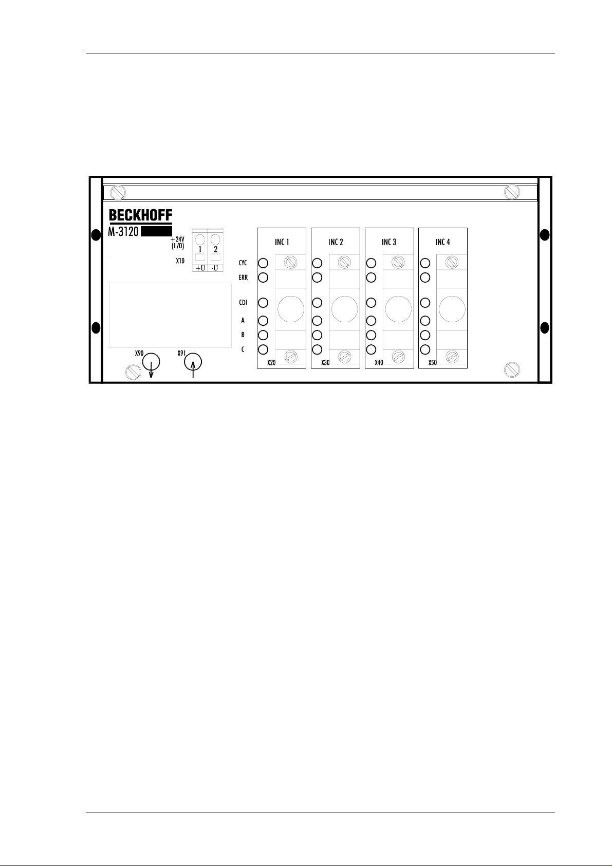
1. Function description hardware
M3120
The periphery module M3120 establishes the connection of four incremental encoders for the
II/O-Lightbus system. It contains three separate power supplies for logic (5V) and pick off
power supply (5/15V) and the level adjustment from 15 V down to 5V. 5 V or 15 V encoder
can be connected to the incremental box M3120, either with or without complementary
channels.
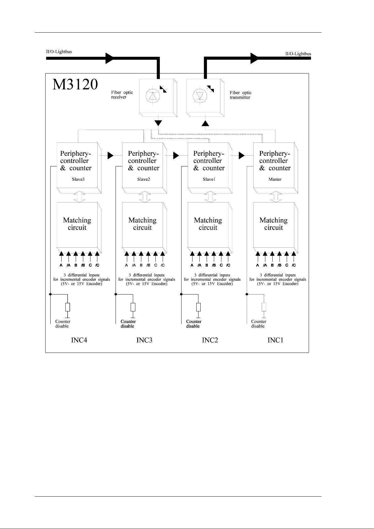
All digital functions are integrated in four separate periphery controller (LCA circuit):
- 24 bit UP/DOWN counter with a limiting frequency of 1.25 MHz.
- Input "counter disable"
- 24 bit latch for counter position at zero impulse.
- Squareness decoder with adjustable 1, 2 or 4 times evaluation
- Selective computation of complementary signals (fewer interferences)
- Connection to the II/O-Lightbus with all functions:
addressing, interrupt, address counting, decrease transmission intensity,
cycle and error LED
- Read, set and activate commands for counter and zero impulse register via fibre
optic II/O-Lightbus
Date 20.10.94 Version 1.1 Page 3 of 14
Page 4
M3120 Incremental encoder 4x Beckhoff II/O-Lightbus
Basic circuit diagram
Page 4 of 14 Version 1.1 Date 20.10.94
Page 5

M3120 Incremental encoder 4x Beckhoff II/O-Lightbus
2. Function description software
Counter functions
- The counter commands are sent in data byte D0 to the module M3120.
- In the data byte D0 the counter status byte is received .
- the counter command byte can only be written
- the counter status byte can only be read.
Counter command byte
In order to transmit commands to the module M3120, the following bits of the counter
command byte can be set and then written to the data byte D0 of an II/O-Lightbus telegram.
76563210
* * * * EL SC RL RC
Bit Value Signal Function
0 RC=1 READ
COUNTER
1 RL=1 READ
LATCH
2SC=1SET
COUNTER
3 EL=1 ENABLE
LATCH
Read 24 bit counter
(D1 = LOW byte, D2 = MID byte, D3 = HIGH byte)
Read 24 bit zero point latch
(D1 = LOW byte, D2 = MID byte, D3 = HIGH byte)
The zero point value (see EL command) is only valid, if the LATCH
VALID bit LV is set in the counter sta tus byte. Only a single read
command can be executed at a time. If in a command byte RC=1 and
RL=1, then no value is read
.
Set counter
The counter is only set, if 0001xxxxb is the value in the control byte
of the II/O telegram.
Activate the zero point latch
the counter is stored in a 24 bit register at the fir st zer o impulse afte r
the EL command was transmitted. Using the RL command the value
can be read many times at any tim e, The LV bit is only dele ted after
the EL command was transmitted. It is only set again, if a zero point
value was stored. The EL com mand is only executed, if 0001xxxx
is the value in the control byte of the II/O telegram.
Date 20.10.94 Version 1.1 Page 5 of 14
Page 6

M3120 Incremental encoder 4x Beckhoff II/O-Lightbus
Bit Value Signal Function
4 - - not used
5 - - not used
6 - - not used
7 - - not used
Rem.: The READ, SET and ENABLE commands can be transmitted in any form.
Counter status byte
After an II/O-Lightbus read operation the counter status of the M3120 points to the module in
the data byte DO. The bits of the counter command byte stand for the following functions :
76563210
STAT KOM LV GF2 GF1 GF0 EE1 EE0
Bit Signal Function
0 EE0 Evaluation mode;
must be selectet inside the D- SUB connector by bridges to GND
1 EE1 *)
2GF0
3GF1
4GF2
a low pass filter is adjustable by software
the low pass filter is abjustable to 1250 kHz by hardware
5 LV zero point value valid
LV = 0
The EL command was transmitted, but there was no zero impulse
yet.
LV = 1
the zero point value was latche d
6 KOM COMPLEMENTARY
shows, if a bridge is present in the D-SUB connector
KOM=0
evaluation of normal pick off signals A, B, C; bridge to GND inside
the D-SUB connector
KOM=1
additional evaluation of complementary signals; open, no bridges
inside the D-SUB connector
A, /A, B, /B, C, /C
7 STAT status signal
not in use yet
Page 6 of 14 Version 1.1 Date 20.10.94
Page 7

M3120 Incremental encoder 4x Beckhoff II/O-Lightbus
*)
Evaluation Mode
EE1 EE0 Evaluation
0 0 1 time
0 1 2 times
1 0 4 times
11 -
Rem.: 0 = GND bridge present
1 = open, no bridge
inside the D-SUB connector ( 15 pins)
II/O-Setup entry
After pasting a module M3120 (incremental encoder 4 times) into the II/O-Lightbus,
following entries have to be made in the II/O-Setup.
Attention: Incremental encoder INC4 must be the fi rst entry and INC1 the fourth entry
in the II/O-Setup Table (look to the example below and to the basic circui t diagram on
page 4):
Example:
Date 20.10.94 Version 1.1 Page 7 of 14
Page 8

M3120 Incremental encoder 4x Beckhoff II/O-Lightbus
3. Technical data
Pick Off Connection
Pick Off Voltage
Inputs
Input spezification
Input level
Input delay
Counter
Limiting frequency
Squarness decoder
A, A(inv), B, B(inv), C, C(inv),
5 V DC / 15 V DC max 1A, resistable against short
circuit
optional at D-SUB connector
"Counter disable"
24 V DC, 10 mA
0 - 8 V =LOW
15 - 24 V =HIGH
0,1 ms RC filter
Inputs "Counter disable"
24 bit binary
1 MHz
1-2-4 times evaluation
Zero impulse latch
Commands
Data connection
Transmission rate
Power supply
Input current
24 bit
set, read, activate
II/O-Lightbus system
2,5 MBaud, 25µsec for 32 bit
24 V DC (±10%)
0,1 A (without encoder load)
Page 8 of 14 Version 1.1 Date 20.10.94
Page 9

M3120 Incremental encoder 4x Beckhoff II/O-Lightbus
Housing
Size (W*H*D)
Weight
Operating temperature
Storage temperature
EMI resistance
Vibration resistance
compact aluminium housing
for terminal rail mount
170*76*68 mm
600 g
±0..+55 °C
-20..+70 °C
IEC 801 T4, class 4: 2 kV for signal lines
4 kV for power supply lines
acc. IEC 68-2-29 (vibration and shock)
Date 20.10.94 Version 1.1 Page 9 of 14
Page 10

M3120 Incremental encoder 4x Beckhoff II/O-Lightbus
4. Installation
The module M3120 is connected to the fibre optic ring using fibre optic connectors (Beckhoff
Z1000). The maximum length of the FO cable, leading to the neighbouring boxes, should not
be more then 600 m for glass fibre or 45 m for other fibres. These values are only valid if for
bending the cable a radius of at least 30 mm is used. If there are no glass fibres used, no
special tools are needed for installation of the plugs.
The module M3120 is installed dezentralized from the machine. Sensors and actors are
connected to the box directly by D-SUB connectors (connector X20, X30, X40, X50).
You can take the power supply for a 5 V or 15 V incremental encoder directly from this
S-SUB connectors.
The LEDs show the status of the module.
Configuration
You can select the times of evaluation over bridges to GND inside the D-SUB connector:
EE1 EE0 evaluation
bridge to
GND
bridge to
GND
open,
no bridge
open,
no bridge
bridge to
GND
open,
no bridge
bridge to
GND
open,
no bridge
1 time
2 times
4 times
-
In case an encoder with single outputs is to be connected, the input "Kom" must be connected
to GND (inside the D-SUB connector X20, X30, X40, X50).
In case an encoder eith complementary outputs is to be connected, the bridge "JP" has to be
removed.
Power supply
A two pin plug in connector is used to establish the 24 V DC power supply. (X10)
Page 10 of 14 Version 1.1 Date 20.10.94
Page 11

M3120 Incremental encoder 4x Beckhoff II/O-Lightbus
Date 20.10.94 Version 1.1 Page 11 of 14
Page 12

M3120 Incremental encoder 4x Beckhoff II/O-Lightbus
5. Connection table
Pin assignment
CONNECTOR X10
Connector Pin Signal Description
X10 1 +U
X10 2 -U
CONNECTOR X20
Control voltage +24V
Ground
Connector Pin Signal Description
X20 1 Kom
X20 2 +24V
X20 3 EE1
X20 4 +5V
X20 5 C
X20 6 B/
X20 7 GND
X20 8 A
X20 9 CDI
X20 10 +15V
X20 11 EE0
X20 12 C/
X20 13 GND
X20 14 B
X20 15 A/
Input complementary signals INC1
+24V INC1
Evaluation 1 time, 2 times, 4 times INC1
+5V encoder supply INC1
Channel C INC1
Channel B (inverted) INC1
GND encoder supply INC1
Channel A INC1
Input „Counter disable“ INC1
+15V Encoder supply INC1
Evaluation 1 time, 2 times, 4 times INC1
Channel C (inverted) INC1
GND INC1
Channel B IN C1
Channel A (inverted) INC1
Page 12 of 14 Version 1.1 Date 20.10.94
Page 13

M3120 Incremental encoder 4x Beckhoff II/O-Lightbus
CONNECTOR X30
Connector Pin Signal Description
X30 1 Kom
X30 2 +24V
X30 3 EE1
X30 4 +5V
X30 5 C
X30 6 B/
X30 7 GND
X30 8 A
X30 9 CDI
X30 10 +15V
X30 11 EE0
X30 12 C/
X30 13 GND
X30 14 B
X30 15 A/
Input complementary signals INC2
+24V INC2
Evaluation 1 time, 2 times, 4 times INC2
+5V encoder supply INC2
Channel C INC2
Channel B (inverted) INC2
GND encoder supply INC2
Channel A INC2
Input „Counter disable“ INC2
+15V Encoder supply INC2
Evaluation 1 time, 2 times, 4 times INC2
Channel C (inverted) INC2
GND INC2
Channel B IN C2
Channel A (inverted) INC2
CONNECTOR X40
Connector Pin Signal Description
X40 1 Kom
X40 2 +24V
X40 3 EE1
X40 4 +5V
X40 5 C
X40 6 B/
X40 7 GND
X40 8 A
X40 9 CDI
X40 10 +15V
X40 11 EE0
X40 12 C/
X40 13 GND
X40 14 B
X40 15 A/
Input complementary signals INC3
+24V INC3
Evaluation 1 time, 2 times, 4 times INC3
+5V encoder supply INC3
Channel C INC3
Channel B (inverted) INC3
GND encoder supply INC3
Channel A INC3
Input „Counter disable“ INC3
+15V Encoder supply INC3
Evaluation 1 time, 2 times, 4 times INC3
Channel C (inverted) INC3
GND INC3
Channel B IN C3
Channel A (inverted) INC3
Date 20.10.94 Version 1.1 Page 13 of 14
Page 14

M3120 Incremental encoder 4x Beckhoff II/O-Lightbus
CONNECTOR X50
Connector Pin Signal Description
X50 1 Kom
X50 2 +24V
X50 3 EE1
X50 4 +5V
X50 5 C
X50 6 B/
X50 7 GND
X50 8 A
X50 9 CDI
X50 10 +15V
X50 11 EE0
X50 12 C/
X50 13 GND
X50 14 B
X50 15 A/
Input complementary signals INC3
+24V INC3
Evaluation 1 time, 2 times, 4 times INC3
+5V encoder supply INC3
Channel C INC3
Channel B (inverted) INC3
GND encoder supply INC3
Channel A INC3
Input „Counter disable“ INC3
+15V Encoder supply INC3
Evaluation 1 time, 2 times, 4 times INC3
Channel C (inverted) INC3
GND INC3
Channel B IN C3
Channel A (inverted) INC3
Page 14 of 14 Version 1.1 Date 20.10.94
 Loading...