

Page 1

M2510 Analog Input Beckhoff II/O Lightbus System
M2510 Analog Input
Technical Description
Eiserstraße 5 Phone: +495246/963-0
33415 Verl Fax: +495246/963-149
Date: 20.08.93 Version : 2.0 Page 1 of 11
Page 2

M2510 Analog Input Beckhoff II/O Lightbus System
Table of Contents
1. Function Description - Hardware..................................................3
2. Function Description - Software....................................................5
3. Technical Data.................................................................................6
4. Installation Notes.............................................................................7
5. Connections Table.........................................................................11
Page 2 of 11 Version : 2.0 Date: 20.08.93
Page 3
M2510 Analog Input Beckhoff II/O Lightbus System
1. Function Description - Hardware
M2510
General
The module M2510 is an input module used in the II/O system. By ADU four analog input
values in the form
a) 0 to +10V
b) 0 to 1V
c) 0 to 20mA
d) -10 V to +10V
e) -1 V to +1V
can be used. The resolution is 12 bit, so that, in a single telegram of the II/O system parallel
transmission of 2 ADU's is possible.
The whole module uses 2 addresses in the II/O system.
There are four LEDs for system diagnosis. Working normally, only the green LEDs "CYCLE
(XILINX1)" and "CYCLE (XILINX2)" are switched on. In case an error is detected the red
"ERROR (XILINX1)" "ERROR (XILINX2)" LEDs are switched on (according to the type of
failure, one or two of the LEDs).
Date: 20.08.93 Version : 2.0 Page 3 of 11
Page 4
M2510 Analog Input Beckhoff II/O Lightbus System
-15V
+15V/+24V
GND
Ain 1 Ain 2
Basic circuit diagram
4 Analog inputs
Ain 3
Ain 4
Page 4 of 11 Version : 2.0 Date: 20.08.93
Page 5

M2510 Analog Input Beckhoff II/O Lightbus System
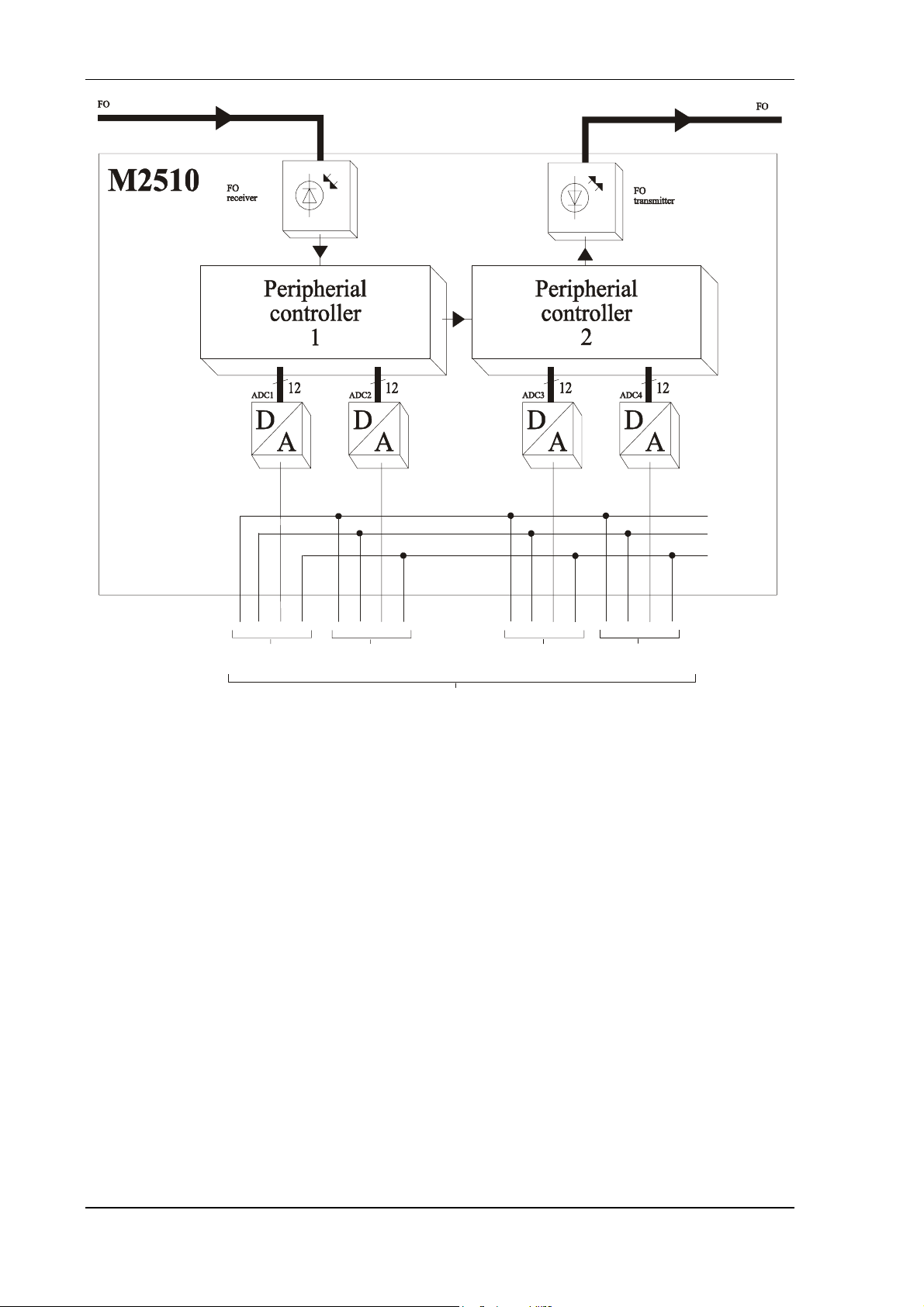
2. Function Description - Software
The 4 ADCs work in stand alone mode. They are triggered by the 'CYCLE' signal, when the
telegram is received.
When the twelve bit of data are read, the transformation result of the previous cycle is used.
There is no need for selection or other communications, since all control signals needed are
created by the hardware.
As there are always 2 ADCs read in a 32 bit telegram, two addresses in the II/O system have
to be reserved for the whole module.
II/O Lightbus
Address 1
LSB
MSB
ADC 2 ADC 1
Port D3 Port D2 Port D1 Port D0
DDDD DDDD DDDD DDDD
xxxx DDDD xxxx DDDD
II/O Lightbus
Address 2
LSB
MSB
ADC 4 ADC 3
Port D3 Port D2 Port D1 Port D0
DDDD DDDD DDDD DDDD
xxxx DDDD xxxx DDDD
Date: 20.08.93 Version : 2.0 Page 5 of 11
Page 6

M2510 Analog Input Beckhoff II/O Lightbus System
3. Technical Data
Analog Inputs
Analog Specifications
Transformation Time
Connections
Data Connections
Transmission Rate
Support Voltage
Connection
Supply Voltage
Input Current
max. 4
Uin = -10 V to 10 V ,
(voltage input)
Iin = 0 to 20 mA (current input)
burden 50 Ohm / 500 Ohm switchable
resolution: 12 Bit
10 µs
plug-in unit; +,-,signal
fibre optic, II/O Lightbus System
2,5 MBaud, 25 µs for 32 bit
±15 V, 80 mA total load, short cirquit proof
Option: +24 V/-15 V
24 V DC (±10 %)
0,17 A (at 24 V DC without support voltage
load)
Input Impedance
Cartridge
Size (w*h*d)
Weight
Working Temperature
Storage Temperature
1 MOhm using unipolar voltage measuring,
2 MOhm using bipolar voltage measuring,
50 Ohm / 500 Ohm measuring the current
closed cartridge, can be installed to cartridge
carrier according to DIN EN 50022, 50035
166 * 76 * 68 mm
about 700 g
0 .. +55 °C
-20 .. +70 °C
Page 6 of 11 Version : 2.0 Date: 20.08.93
Page 7

M2510 Analog Input Beckhoff II/O Lightbus System
4. Installation Notes
Mounting
The M2510 is connected to the fibre optic ring using fibre optic connections (Beckhoff
Z1000). The maximum length of the FO cable, leading to the neighbouring boxes, should not
be more then 600m for glass fibre or 45 meters for other fibres. These values are only valid if
for bending the cable a radius of at least 30 mm is used. If plastic fibres are used, no special
tools are needed for installation of the plugs.
The M2510 is installed at the machine or simply by installing it to a cartridge carrier
according to DIN EN 50022 or DIN EN 50035.
Configuration
Before setting the system to work the desired modes of the Analog transformers have to be
adjusted by setting certain jumpers according to the following configuration table:
Input Jx.1 Jx.2 Jx.3 Jx.4 Jx.5 Jx.6
0 to 10V o cl cl cl o o
burden 50 Ohm
0 to 20 mA
burden 500 Ohm
0 to 20 mA
-10 V to +10 V o cl o o cl o
0 to 1 V o o cl cl o o
-1 V to +1 V o o o o cl o
where : cl = closed
o = open
and x = 1,2,3,4
cl
o
o
cl
cl
cl
cl
cl
o
o
o
cl
Date: 20.08.93 Version : 2.0 Page 7 of 11
Page 8

M2510 Analog Input Beckhoff II/O Lightbus System
Adjusting and Testing of Analog Inputs
The module M2510 is configured to the measuring range 0 to 10V per default. It can be
delivered with customized configuratin and adjustment.
Every analog input of the M2510 can be adjusted indepenedently of the other inputs if
necessary (e.g. change of the measuring range).
First the appropriate jumpers have to be set. Then an adjustment of the mode concerned can
be done:
a) unipolar 0-10 V
- connect input with ground
- read channel by II/O Lightbus test program or other II/O-Lightbus software
(continuously to provide constant transformation)
- use potentiometer "Offset unipolar" to adjust the value read to "0"
b) unipolar 0-1 V
- connect input with ground
- read channel by II/O Lightbus test program or other II/O-Lightbus software
(continuously to provide constant transformation)
- use potentiometer "Offset unipolar" to adjust the value read to "0"
- connect and adjust precisely 1V to the input
and then adjust by using potentiometer"GAIN" to the value "FFFh
c) unipolar 0-20 mA
- connect input with ground
- read channel by II/O Lightbus test program or other II/O-Lightbus software
(continuously to provide constant transformation)
- use potentiometer "Offset unipolar" to adjust the value read to "0"
- connect and adjust precisely 20mA to the input
(alternatively 1V with 50 Ohm burden, or 10V with 500 Ohm burden)
and then adjust by using potentiometer"GAIN" to the value "FFFh
d) bipolar +/-10 Volt
- connect input with ground
- read channel by II/O Lightbus test program or other II/O-Lightbus software
(continuously to provide constant transformation)
- adjust by using potentiometer "Offset bipolar" the read in value to "800h"
Page 8 of 11 Version : 2.0 Date: 20.08.93
Page 9

M2510 Analog Input Beckhoff II/O Lightbus System
e) bipolar +/-1 Volt
- connect input with ground
- read channel by II/O Lightbus test program or other II/O-Lightbus software
(continuously to provide constant transformation)
- adjust by using potentiometer "Offset bipolar" the read in value to "800h"
- connect and adjust precisely -1V to the input
and then adjust by using potentiometer"GAIN" to the value "000h
Spannungsversorgung
There is a two-pin terminal (X10 Pin1+2) for the supply voltage with connections for control
logic (+).
Date: 20.08.93 Version : 2.0 Page 9 of 11
Page 10

M2510 Analog Input Beckhoff II/O Lightbus System
50 / 500 Ohm
Switch over
burden resistor
select operation mode
Channel 1
Jumper J1.5
Jumper J1.4
Jumper J1.3
Jumper J1.2
Jumper J1.1
4
1
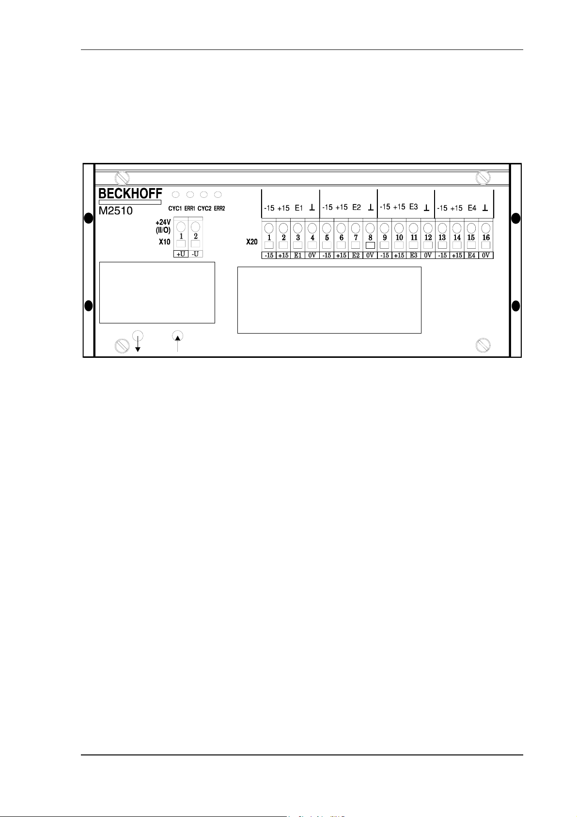
Connector X20
X20
Channel 1
X10
(II/O)
+24V
LD4 LED "ERR2" XILINX2
LD3 LED "CYC2" XILINX2
LD2 LED "ERR1" XILINX1
LD1 LED "CYC1" XILINX1
ground
Adjustment
Poti G1 ("GAIN")
Poti BO1 ("Bipolar Offset")
Poti UO1 ("Unipolar Offset")
FO receiver
FO transmitter
Connector X10
Control power supply +24V
Analog input
M2510
Page 10 of 11 Version : 2.0 Date: 20.08.93
Page 11

M2510 Analog Input Beckhoff II/O Lightbus System
5. Connections Table
Pin assignment with signal description
Conector X10
Connector Pin Signal Description
X10 1 +
X10 2 -
Connector X20
Connector Pin Signal Description
X20 1 -15 V
X20 2 +15 V
X20 3 E1
X20 4 GND
X20 5 -15 V
X20 6 +15 V
X20 7 E2
X20 8 GND
X20 9 -15 V
X20 10 +15 V
X20 11 E3
X20 12 GND
X20 13 -15 V
X20 14 +15 V
X20 15 E4
X20 16 GND
Control power supply +24 V
ground
Support voltage -15 V DC
Support voltage +15 V DC, Option:+24 V DC
Analog input channel 1
ground
Support voltage -15 V DC
Support voltage +15 V DC, Option:+24 V DC
Analog input channel 2
ground
Support voltage -15 V DC
Support voltage +15 V DC, Option:+24 V DC
Analog input channel 3
ground
Support voltage -15 V DC
Support voltage +15 V DC, Option:+24 V DC
Analog input channel 4
ground
Date: 20.08.93 Version : 2.0 Page 11 of 11
 Loading...