

Page 1

M2400 Analog Output Beckhoff I/O-System
M2400 Analog Output
Technical Description
Eiserstraße 5 phone 05246/709-0
33415 Verl fax 05246/70980
Date : 11.06.2002 Version : 2.1 Page 1 of 1
Page 2

M2400 Analog Output Beckhoff I/O-System
Table of Contents
1. Function Description Hardware ....................................................3
2. Function Description Software ......................................................5
3. Technical Data.................................................................................6
4. Installation .......................................................................................7
5. Table of Connections ....................................................................12
page 2 of 2 Version : 2.1 Date : 11.06.2002
Page 3
M2400 Analog Output Beckhoff I/O-System
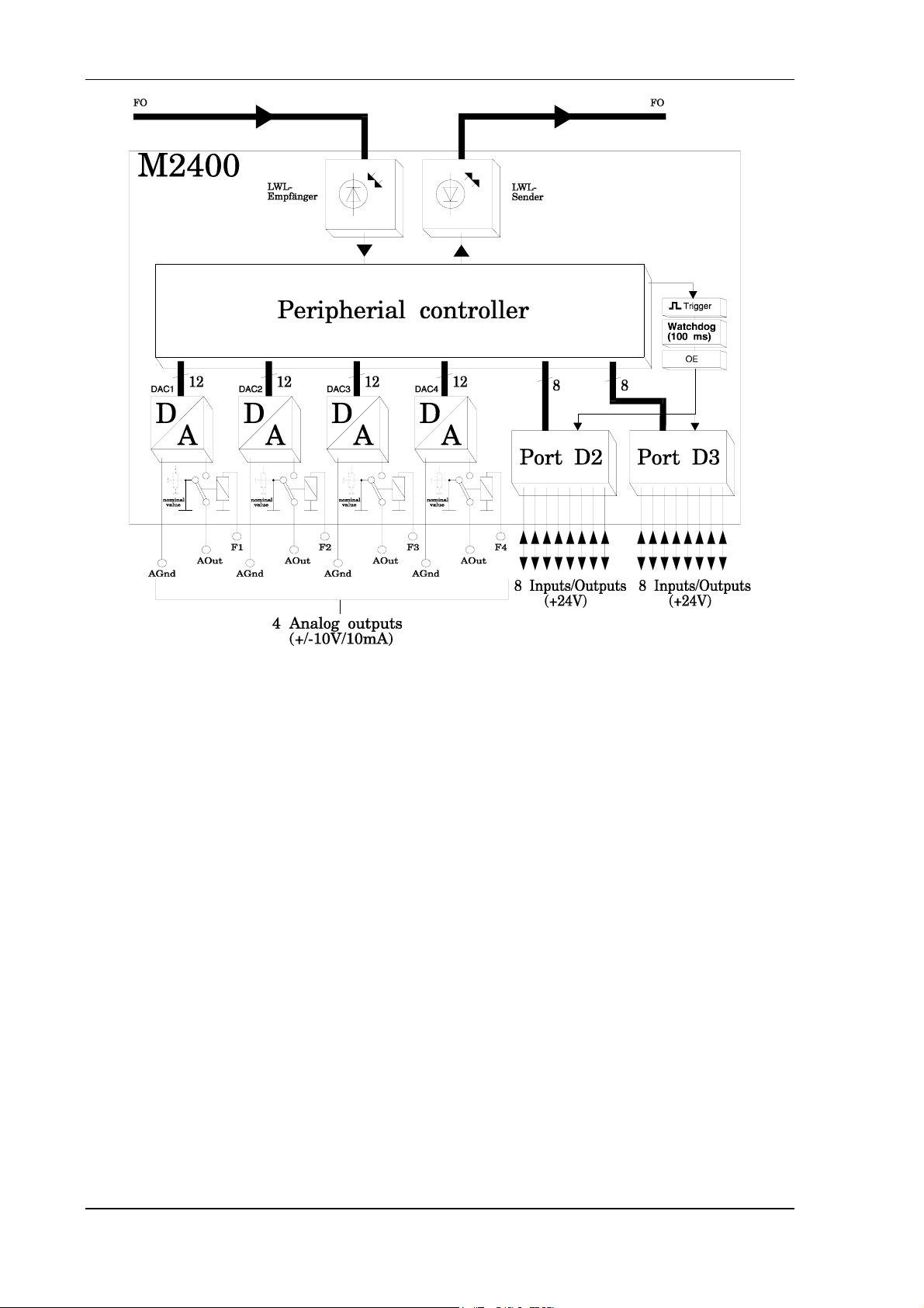
1. Function Description Hardware
M2400
About the Hardware
The parallel module M2400 is an input / output module used in the II/O system. There are 16
standard 24 V inputs / outputs, which achieve 2 ports of 8 bit each, and four analog output
channels.
Each input / output has an LED, that indicates the current state. Furthermore there are three
LED's installed used for diagnosis of the II/O fibre optical ring:
LD1 The green 'CYCLE' LED is switched on by each start bit of a telegram and is
switched off again by the stop bit.
LD2
LD3
In case an error is detected, all outputs are reset.
The red 'ERROR' LED is switched on after recognition of bad telegram (checksum,
frame). After a sequence of three correct telegrams (checksum, frame) were processed it
is switched off again.
The green LED 'WATCHDOG' is switched on by a valid writing telegram with matching
address. If no telegram with the properties defined above is recognised for the next
100 ms a special unit of the module switches off all outputs.
Date : 11.06.2002 Version : 2.1 Page 3 of 3
Page 4
M2400 Analog Output Beckhoff I/O-System
Basic Circuit Diagram
page 4 of 4 Version : 2.1 Date : 11.06.2002
Page 5
M2400 Analog Output Beckhoff I/O-System
2. Function Description Software
The four ports D0..D3 correspond to the data bytes in the FO transmission protocol.
Analog Output
Through the analog channels 1 to 4 of the M2400 analog values of 12 bit resolution are
transmitted in a voltage range of - 10V .. + 10V. The selection of a certain DAC is done by a
logic "0" one of the most significant 4 bits of port D1.
The transmission of the 12 bit data word is done by the least significant four bits of port D1
and the eight bits of port D0.
SELECT PORT D1
MSB LSB
DAC 1
DAC 2
DAC 3
DAC 4
0 1 1 1 DDDD DDDD DDDD
1 0 1 1 DDDD DDDD DDDD
1 1 0 1 DDDD DDDD DDDD
1 1 1 0 DDDD DDDD DDDD
4 bit
select
low-active
PORT D0
MSB LSB
12 bit data
OUTPUT PORT D1
MSB LSB
+10V
0V
SSSS 0 0 0 0 0 0 0 0 0 0 0 0
SSSS 1 0 0 0 0 0 0 0 0 0 0 0
PORT D0
MSB LSB
-10V
SSSS 1 1 1 1 1 1 1 1 1 1 1 1
4 bit
select
low-active
12 bit data
Date : 11.06.2002 Version : 2.1 Page 5 of 5
Page 6

M2400 Analog Output Beckhoff I/O-System
3. Technical Data
Analog Outputs
Analog Specifications
Error, linearity
Rise time
Inputs / Outputs
input switching vcoltages
input delay
Input Specifications
Output Specifications
Output check
max. 4
U
= ±10 V , I
out
Resolution : 12 Bit
+/- 1 LSB
10 us von -10V ==> +10V
16, can be configured for each port;
LED shows state of all inputs / outputs
0 - 8V = LOW
15 - 24V = HIGH
0,7 ms RC network
6,8 ms input latch
24 V DC, 10 mA, digital filter
24 V DC, max. 500 mA, short circuit proof
watchdog system (100ms)
= 0 to 20 mA
out
Connections
Data Connection
Transmission Rate
Supply Voltage
Input Current
Cartridge
Size (B * W * D)
Weight
Working Temperature
Storage Temperature
a) can be connected for digital I/O ; +,-,signal
b) for analog output; signal,-,potential free contact, 1
permission input 24 VDC for each channel
fibre optic II/O system
2,5 MBaud, 25 µs for 32 Bit
24 V DC (± 10%)
0,1 A (without load and input currents)
Aluminium profile cartridge, can be installed to
cartridge carrier according to DIN EN 50022, 50035
270 * 76 * 68 mm
about 1100 g
±0..+55 øC
-20..+70 øC
page 6 of 6 Version : 2.1 Date : 11.06.2002
Page 7

M2400 Analog Output Beckhoff I/O-System
4. Installation
The M2400 is connected to the fibre optic ring, using fibre optic connectors (Toshiba). The
maximum length of the FO cable, leading to the neighbouring boxes, should not exceed
600m for glass fibre or 45 meters for other fibres. These values are valid only if for bending
the cable a radius of at least 30 mm is used. When using plastic FO, no special tools are
needed for installation of the plugs.
Common actors and sensors are connected directly to the inputs / outputs (using "+,-,signal" ).
The M2400 is installed at the machine or simply by installing it to a cartridge carrier
according to DIN EN 50022 or DIN EN 50035
Configuration
The ports D0 and D1 are used for analog output. D2 and D3 can be configured as input or
output according to the way they are used.
Each I/O port of the M2400 can be configured as input or as output. This does not dependent
on the configuration of the other ports. There are DIP switches used for configuration.
The DIP switches are assigned as follows :
Switch 1 => Port D0 mast always be 'ON'
Switch 2 => Port D1 must always be 'ON'
Switch 3 => Port D2
Switch 4 => Port D3
Depending on the state of the switches, the port is input or output :
'ON' => port is output
'OFF' => port is input
Date : 11.06.2002 Version : 2.1 Page 7 of 7
Page 8

M2400 Analog Output Beckhoff I/O-System
The DIP switch for ports D0 and D1 must be 'ON', to enable the analog channels to work as
output.
ATTENTION:
Configuring a port as input ( switch "OFF") all of the eight output controller
ICs of the port concerned have to be removed.
If the ICs are not removed the port is not functional as input, the module is not
damaged.
View under the M2400 XILINX board
The following module configuration is possible by setting jumpers 1 to 2 :
Jumper 1
Watchdog on / off
for Port D2 and D3
Jumper 2
If this jumper is set the 'Watchdog' function is switched off.
This means if an error is detected the outputs of Port D2 and
D3 are not switched off.
Latch on / off
standard configuration is jumper 'set'
inputs are latched in intervals of 6,8 ms
otherwise inputs are scanned continuously
page 8 of 8 Version : 2.1 Date : 11.06.2002
Page 9

M2400 Analog Output Beckhoff I/O-System
Enabling the analog Outputs
In order to take the analog voltages from the connections, the appropriate relay of a certain
analog channel has to be selected by applying 24 VDC to the relay input F1..F4 (connector
X22).
As long as the enable input is not activated the output voltage is fixed to 0V or it can be
adjusted to a default value in the range from -1V to +1V.
The selection can be done by one of the digital outputs too, if the output is connected to the
relay input.
Each pair of contacts 1F, 2F, 3F and 4F on connector X20 provides a normally open switch
for use on sens lines (I
=100 mA, U
max
max
=24V).
Date : 11.06.2002 Version : 2.1 Page 9 of 9
Page 10

M2400 Analog Output Beckhoff I/O-System
Calibration
Each analog output of the M2400 can be calibrated separately.
The output that is to be calibrated has to be enabled by the corresponding relay.
For zero voltage calibration the 12 bit data word 800H has to be transmitted to the M2400.
Zero voltage is calibrated by the potentiometer 'OFFSET'.
For calibration of gain the 12 bit data word FFFH or OOOH is transmitted to the M2400. The
analog output is calibrated by the potentiometer 'PITCH' to either -10V or +10V.
The potentiometer for adjustment and the default value can be found on the module after
removing the small lid below X20.
The default output value is fixed to or by factory preset. Activation of level potentiometers is
done by cutting a marked piece of copper trace on the pcb
Power Supply
The following connectors are used for powers supply :
(1) two pole plug connection for control logic (X10 Pin1+2)
(2) two pole plug connection for outputs (X30 Pin1+2)
(16 outputs)
(3) two pole plug connection for inputs (X31 Pin1+2)
(16 inputs)
(4) two pole plug connection for ground (X32 Pin1+2)
page 10 of 10 Version : 2.1 Date : 11.06.2002
Page 11

M2400 Analog Output Beckhoff I/O-System
Date : 11.06.2002 Version : 2.1 Page 11 of 11
Page 12

M2400 Analog Output Beckhoff I/O-System
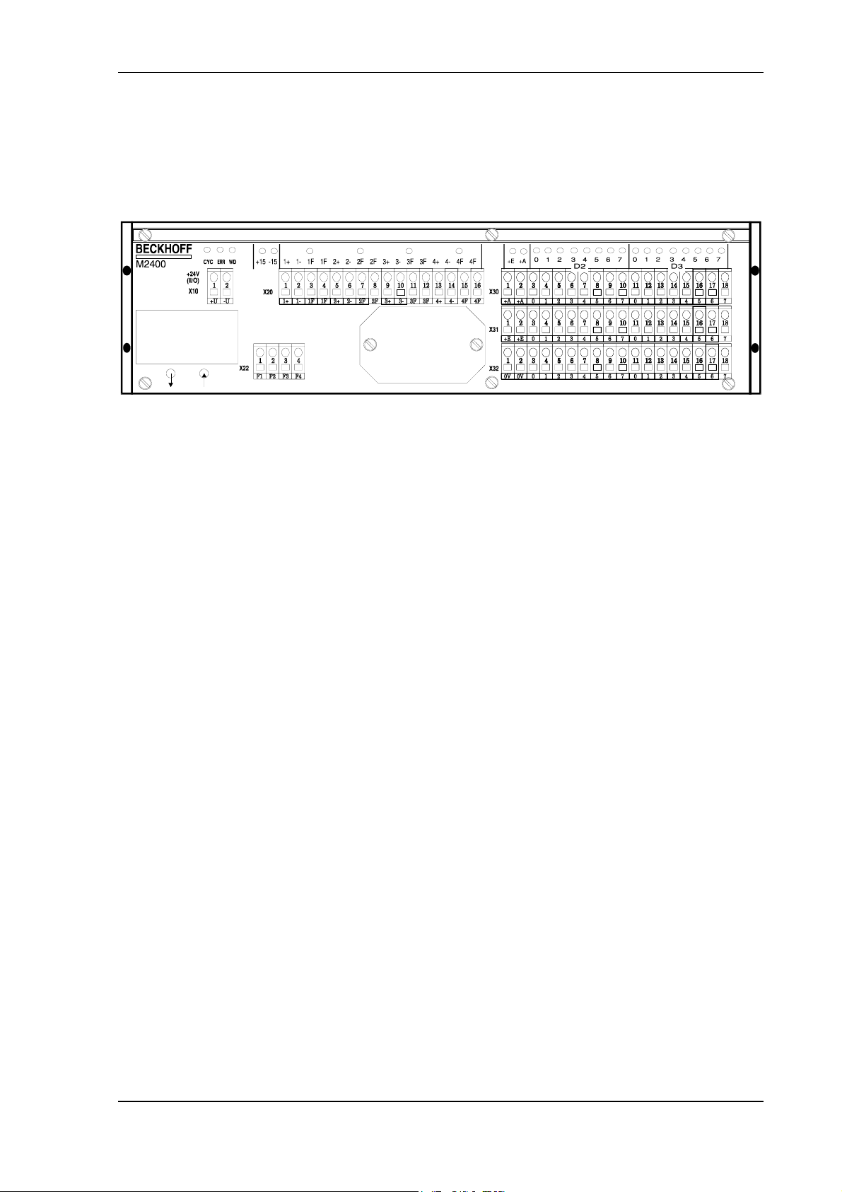
5. Table of Connections
Connector pin assignment with Signal Description
CONNECTOR X10
Connector Pin Signal Description
X10 1 +U
X10 2 -U
CONNECTOR X20
+24V control power supply
GND ground
Connector Pin Signal Description
X20 1 1+
X20 2 1X20 3 1F
X20 4 1F
X20 5 2+
X20 6 2X20 7 2F
X20 8 2F
X20 9 3+
X20 10 3X20 11 3F
X20 12 3F
X20 13 4+
X20 14 4X20 15 4F
X20 16 4F
Analog voltage output channel 1
GND ground for analog output channel 1
Potential free contact channel 1
Potential free contact channel 1
Analog voltage output channel 2
GND ground for analog output channel 2
Potential free contact channel 2
Potential free contact channel 2
Analog voltage output channel 3
GND ground for analog output channel 3
Potential free contact channel 3
Potential free contact channel 3
Analog voltage output channel 4
GND ground for analog output channel 4
Potential free contact channel 4
Potential free contact channel 4
CONNECTOR X22
Connector Pin Signal Description
X22 1 F1
X22 2 F2
X22 3 F3
X22 4 F4
Input +24V Enable channel 1
Input +24V Enable channel 2
Input +24V Enable channel 3
Input +24V Enable channel 4
page 12 of 12 Version : 2.1 Date : 11.06.2002
Page 13

M2400 Analog Output Beckhoff I/O-System
CONNECTOR X30
Connector Pin Signal Description
X30 1 +A
X30 2 +A
X30 3 D2.0
X30 4 D2.1
X30 5 D2.2
X30 6 D2.3
X30 7 D2.4
X30 8 D2.5
X30 9 D2.6
X30 10 D2.7
X30 11 D3.0
X30 12 D3.1
+24V supply for output
+24V supply for output
Bit 0 of Data byte 2
D2.0 is output,
if DIL switch S1 = ON
D2.0 is input,
if DIL switch S1 = OFF
Bit 1 of Data byte 2
D2.1 is output,
if DIL switch S1 = ON
D2.1 is input,
if DIL-switch S1 = OFF
Bit 2 of Data byte 2
D2.2 is output,
if DIL switch S1 = ON
D2.2 is input,
if DIL switch S1 = OFF
Bit 3 of Data byte 2
D2.3 is output,
if DIL-switch S1 = ON
D2.3 is input,
if DIL switch S1 = OFF
Bit 4 of Data byte 2
D2.4 is output,
if DIL switch S1 = ON
D2.4 is input,
of DIL switch S1 = OFF
Bit 5 of Data byte 2
D2.5 is output,
if DIL switch S1 = ON
D2.5 is input,
if DIL switch S1 = OFF
Bit 6 of Data byte 2
D2.6 is output,
if DIL switch S1 = ON
D2.6 is input,
if DIL switch S1 = OFF
Bit 7 of Data byte 2
D2.7 is output,
if DIL-switch S1 = ON
D2.7 is input,
if DIL switch S1 = OFF
Bit 0 of Data byte 3
D3.0 is output,
if DIL switch S1 = ON
D3.0 is input,
of DIL switch S1 = OFF
Bit 1 of Data byte 3
D3.1 is output,
if DIL switch S1 = ON
D3.1 is input,
if DIL switch S1 = OFF
Date : 11.06.2002 Version : 2.1 Page 13 of 13
Page 14

M2400 Analog Output Beckhoff I/O-System
continuation connector X30:
Connector Pin Signal Description
X30 13 D3.2
X30 14 D3.3
X30 15 D3.4
X30 16 D3.5
X30 17 D3.6
X30 18 D3.7
Bit 2 of Data byte 3
D3.2 is output,
if DIL switch S1 = ON
D3.2 is input,
if DIL switch S1 = OFF
Bit 3 of Data byte 3
D3.3 is output,
if DIL switch S1 = ON
D3.3 is input,
if DIL switch S1 = OFF
Bit 4 of Data byte 3
D3.4 is output,
if DIL switch S1 = ON
D3.4 is input,
if DIL switch S1 = OFF
Bit 5 of Data byte 3
D3.5 is output,
if DIL switch S1 = ON
D3.5 is input,
if DIL switch S1 = OFF
Bit 6 of Data byte 3
D3.6 is output,
if DIL switch S1 = ON
D3.6 is input,
if DIL switch S1 = OFF
Bit 7 of Data byte 3
D3.7 is output,
if DIL switch S1 = ON
D3.7 is input,
if DIL switch S1 = OFF
page 14 of 14 Version : 2.1 Date : 11.06.2002
Page 15

M2400 Analog Output Beckhoff I/O-System
CONNECTOR X31
Connector Pin Signal Description
X31 1 +E
X31 2 +E
X31 3 +24V
X31 4 +24V
X31 5 +24V
X31 6 +24V
X31 7 +24V
X31 8 +24V
X31 9 +24V
X31 10 +24V
X31 11 +24V
X31 12 +24V
X31 13 +24V
X31 14 +24V
X31 15 +24V
X31 16 +24V
X31 17 +24V
X31 18 +24V
+24V supply inputs
+24V supply inputs
+24V power supply for input 2.0
+24V power supply for input 2.1
+24V power supply for input 2.2
+24V power supply for input 2.3
+24V power supply for input 2.4
+24V power supply for input 2.5
+24V power supply for input 2.6
+24V power supply for input 2.7
+24V power supply for input 3.0
+24V power supply for input 3.1
+24V power supply for input 3.2
+24V power supply for input 3.3
+24V power supply for input 3.4
+24V power supply for input 3.5
+24V power supply for input 3.6
+24V power supply for input 3.7
CONNECTOR X32
Connector Pin Signal Description
X32 1 0V
X32 2 0V
X32 3 0V
X32 4 0V
X32 5 0V
X32 6 0V
X32 7 0V
X32 8 0V
X32 9 0V
X32 10 0V
X32 11 0V
X32 12 0V
X32 13 0V
X32 14 0V
X32 15 0V
X32 16 0V
X32 17 0V
X32 18 0V
GND Supply input/output
GND Supply input/output
GND Input/output D2.0
GND Input/output D2.1
GND Input/output D2.2
GND Input/output D2.3
GND Input/output D2.4
GND Input/output D2.5
GND Input/output D2.6
GND Input/output D2.7
GND Input/output D3.0
GND Input/output D3.1
GND Input/output D3.2
GND Input/output D3.3
GND Input/output D3.4
GND Input/output D3.5
GND Input/output D3.6
GND Input/output D3.7
Date : 11.06.2002 Version : 2.1 Page 15 of 15
 Loading...