

Page 1

M1410 Parallel Input / Output Beckhoff II/O-System
M1410 Parallel Input / Output
Technical Documentation
Eiserstraße 5 phone 05246/709-0
33415 Verl fax 05246/70980
Date : 2.8.94 Version : 2.0 Page 1 of 14
Page 2

M1410 Parallel Input / Output Beckhoff II/O-System
Table of Contents
1. Function Description Hardware....................................................3
2. Function Description Software......................................................5
3. Technical Data.................................................................................6
4. Installation.......................................................................................7
5. Table of Connections....................................................................11
Page 2 von 14 Version : 2.0 Date : 2.8.94
Page 3
M1410 Parallel Input / Output Beckhoff II/O-System
1. Function Description Hardware
M1410
About the Hardware
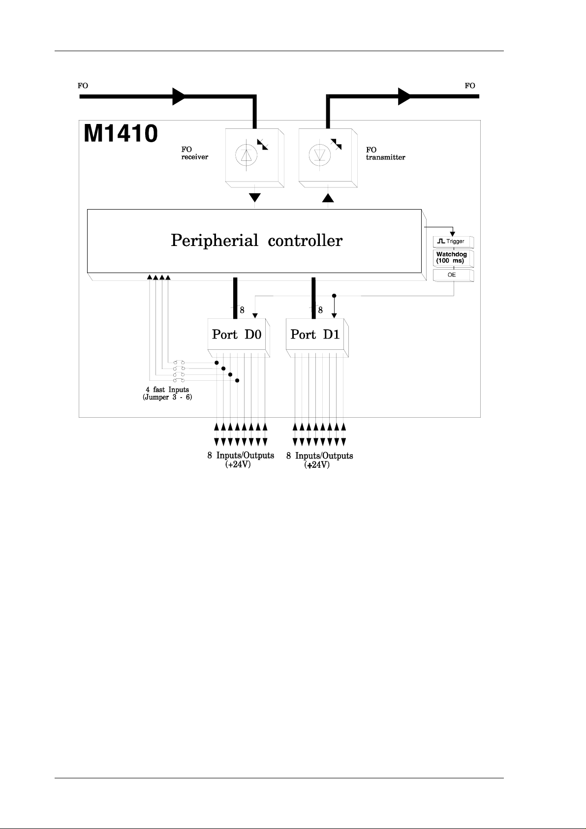
The parallel module M1410 is an input / output module used in the II/O system. There are 16
Standard 24 V inputs / outputs, which achieve 2 ports of 8 bit each.
These 2 ports ( D0,D1 ) correspond to the data bytes in the FO transmissions protocol and
according to the way they are to be used, they can be configured as input or output.
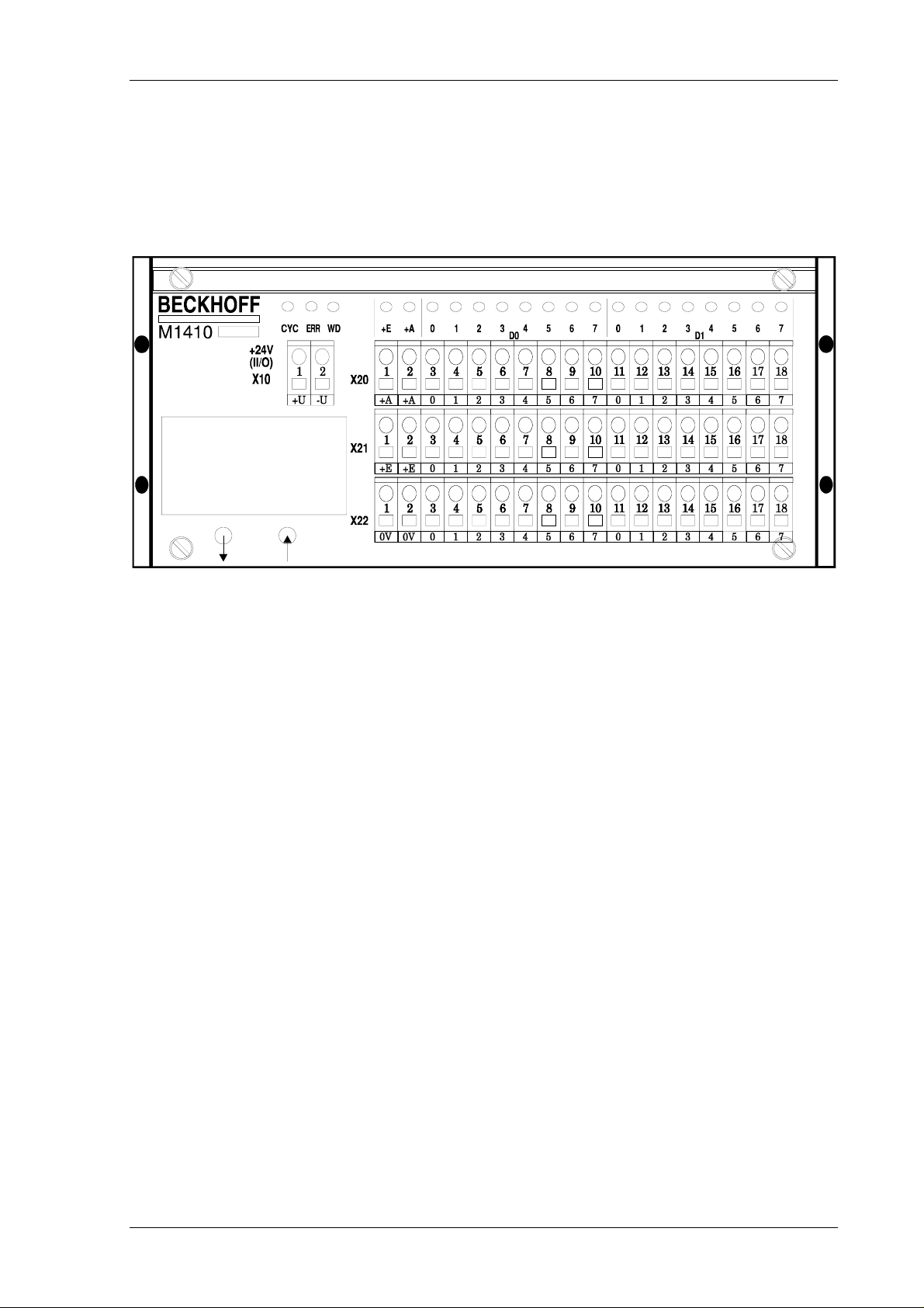
Each input / output has an LED, that indicates the current state. Furthermore there are three
LED’s installed used for diagnosis of the II/O fibre optical ring:
LD1 The green ’CYCLE’ LED is switched on by each start bit of a telegram and is
switched off again by the stop bit.
LD2 The red ’ERROR’ LED is switched on after the recognition of a bad telegram (checksum,
frame). After a sequence of three correct telegrams (checksum, frame) were processed it
is switched off again.
LD3 The green LED ’WATCHDOG’ is switched on by a valid writing telegram with matching
address. If no telegram with the properties defined above is recognised for the next
100 ms a special unit of the module switches off all outputs.
In case an error is detected, all outputs are reset.
Date : 2.8.94 Version : 2.0 Page 3 of 14
Page 4
M1410 Parallel Input / Output Beckhoff II/O-System
Basic Circuit Diagram
Page 4 von 14 Version : 2.0 Date : 2.8.94
Page 5

M1410 Parallel Input / Output Beckhoff II/O-System
2. Function Description Software
Date : 2.8.94 Version : 2.0 Page 5 of 14
Page 6

M1410 Parallel Input / Output Beckhoff II/O-System
3. Technical Data
Inputs / Outputs
Input Specifications
input switching voltages
input delay
Output Specifications
Output check
Connections
Data Connection
Transmission Rate
Supply Voltage
16, can be configured for each port;
LED shows state of all inputs / outputs
24 VDC, 10 mA, digital filter
0 - 8V = LOW
15 - 24V = HIGH
0,7 ms RC network
6,8 ms input latch
24 VDC, max. 500 mA, short circuit proof
watchdog system 100ms
can be connected for 16 I/O; +,-,signal
fibre optic II/O system
2,5 MBaud, 25 µs for 32 Bit
24 VDC (± 10%)
Input Current
Cartridge
Size (B * W * D)
Weight
Working Temperature
Storage Temperature
0,1 A (without load and input currents)
closed, can be installed to cartridge carrier
according to DIN EN 50022, 50035
170 * 76 * 68 mm
about 700 g
±0..+55 øC
-20..+70 øC
Page 6 von 14 Version : 2.0 Date : 2.8.94
Page 7

M1410 Parallel Input / Output Beckhoff II/O-System
4. Installation
The M1410 is connected to the fibre optic ring using fibre optic connections (Toshiba). The
maximum length of the FO cable, leading to the neighbouring boxes, should not be more then
600m for glass fibre or 45 meters for other fibres. These values are only valid, if for bending
the cable a radius of at least 30 mm is used. If there are no glass fibres used, no special tools
are needed for installation of the plugs.
Common actors and sensor are connected directly to the inputs / outputs (using "+,-,signal" ).
The M1410 is installed at the machine or simply by installing it to a cartridge carrier
according to DIN EN 50022 or DIN EN 50035.
Configuration
Each I/O port of the M1410 can be configured as input or as output. This does not depend on
the configuration of the other ports. There are DIP switches under the XILINX board of the
M1410. In order to change the state of the switches the module’s cartridge has to be opened..
The DIP switches are assigned as follows:
switch 1 => port D0
switch 2 => port D1
switch 3 NC, no connectet, set to ’ON’
switch 3 NC, no connectet, set to ’ON’
Date : 2.8.94 Version : 2.0 Page 7 of 14
Page 8

M1410 Parallel Input / Output Beckhoff II/O-System
It depends on the state of the switch whether a port is output or input :
’ON’ => port is output
’OFF’ => port is input
ATTENTION:
Configuring a port as input ( switch "OFF") all of the eight output controller
ICs of the port concerned have to be removed.
If the ICs are not removed the port is not functional as input, but the module
remains undamaged.
View the M1410 XILINX board
The following module configuration is possible by setting jumpers 1 to 2:
Jumper 1
Watchdog on / off
for Port D0 and D1
If this jumper is set the ’Watchdog’ function is switched of f.
This means if an error is detected the outputs set of Port D0
and D1 are not switched off.
Jumper 2
standard configuration is jumper ’set’
input are latched in intervals of 6,8 ms
otherwise inputs are latched permanently
Latch on / off
Page 8 von 14 Version : 2.0 Date : 2.8.94
Page 9

M1410 Parallel Input / Output Beckhoff II/O-System
The following module configuration is possible by setting jumpers 3 to 6:
Fast Inputs M1410 (Interrupt Inputs)
Jumper 3
Jumper 4
Jumper 5
Jumper 6
Fast input II3 :
If jumper connection betwenn port D0.3 and XILINX II3 is
established Fast input is ativated
Fast input II2 :
If jumper connection betwenn port D0.2 and XILINX II3 is
established Fast input is activated
Fast input II1 :
If jumper connection betwenn port D0.1 and XILINX II3 is
established Fast input is activated
Fast input II0 :
If jumper connection betwenn port D0.0 and XILINX II3 is
established Fast input is activated
Power Supply
There are the following connections for power Supply :
(1) two pole plug connection for the controller (X10 Pin1+2)
(2) two pole plug connection for outputs (X20 Pin1+2)
( 16 outputs )
(3) two pole plug connection for inputs X21 Pin1+2)
(16 inputs)
(4) two pole plug connection for ground (X22 Pin1+2)
Date : 2.8.94 Version : 2.0 Page 9 of 14
Page 10

M1410 Parallel Input / Output Beckhoff II/O-System
Page 10 von 14 Version : 2.0 Date : 2.8.94
Page 11

M1410 Parallel Input / Output Beckhoff II/O-System
5. Table of Connections
Connector pin assignment with Signal Description
CONNECTOR X10
Connector Pin Signal Description
X10 1 +U
X10 2 -U
CONNECTOR X20
+24V control power supply
GND ground
Connector Pin Signal Description
X20 1 +A
X20 2 +A
X20 3 D0.0
X20 4 D0.1
X20 5 D0.2
X20 6 D0.3
X20 7 D0.4
X20 8 D0.5
+24V supply for output
+24V supply for output
Bit 0 of Data byte 0
D0.0 is output,
if DIL switch S1 = ON
D0.0 is input,
if DIL switch S1 = OFF
Bit 1 of Data byte 0
D0.1 is output,
if DIL switch S1 = ON
D0.1 is input,
if DIL-switch S1 = OFF
Bit 2 of Data byte 0
D0.2 is output,
if DIL switch S1 = ON
D0.2 is input,
if DIL switch S1 = OFF
Bit 3 of Data byte 0
D0.3 is output,
if DIL-switch S1 = ON
D0.3 is input,
if DIL switch S1 = OFF
Bit 4 of Data byte 0
D0.4 is output,
if DIL switch S1 = ON
D0.4 is input,
of DIL switch S1 = OFF
Bit 5 of Data byte 0
D0.5 is output,
if DIL switch S1 = ON
D0.5 is input,
if DIL switch S1 = OFF
Date : 2.8.94 Version : 2.0 Page 11 of 14
Page 12

M1410 Parallel Input / Output Beckhoff II/O-System
continuation connector X20:
Connector Pin Signal Description
X20 9 D0.6
X20 10 D0.7
X20 11 D1.0
X20 12 D1.1
X20 13 D1.2
X20 14 D1.3
X20 15 D1.4
X20 16 D1.5
X20 17 D1.6
X20 18 D1.7
Bit 6 of Data byte 0
D0.6 is output,
if DIL switch S1 = ON
D0.6 is input,
if DIL switch S1 = OFF
Bit 7 of Data byte 0
D0.7 is output,
if DIL switch S1 = ON
D0.7 is input,
if DIL switch S1 = OFF
Bit 0 of Data byte 1
D1.0 is output,
if DIL switch S1 = ON
D1.0 is input,
if DIL switch S1 = OFF
Bit 1 of Data byte 1
D1.1 is output,
if DIL switch S1 = ON
D1.1 is input,
if DIL switch S1 = OFF
Bit 2 of Data byte 1
D1.2 is output,
if DIL switch S1 = ON
D1.2 is input,
if DIL switch S1 = OFF
Bit 3 of Data byte 1
D1.3 is output,
if DIL switch S1 = ON
D1.3 is input,
if DIL switch S1 = OFF
Bit 4 of Data byte 1
D1.4 is output,
if DIL switch S1 = ON
D1.4 is input,
if DIL switch S1 = OFF
Bit 5 of Data byte 1
D1.5 is output,
if DIL switch S1 = ON
D1.5 is input,
if DIL switch S1 = OFF
Bit 6 of Data byte 1
D1.6 is output,
if DIL switch S1 = ON
D1.6 is input,
if DIL switch S1 = OFF
Bit 7 of Data byte 1
D1.7 is output,
if DIL switch S1 = ON
D1.7 is input,
if DIL switch S1 = OFF
Page 12 von 14 Version : 2.0 Date : 2.8.94
Page 13

M1410 Parallel Input / Output Beckhoff II/O-System
CONNECTOR X21
Connector Pin Signal Description
X21 1 +E
X21 2 +E
X21 3 +24V
X21 4 +24V
X21 5 +24V
X21 6 +24V
X21 7 +24V
X21 8 +24V
X21 9 +24V
X21 10 +24V
X21 11 +24V
X21 12 +24V
X21 13 +24V
X21 14 +24V
X21 15 +24V
X21 16 +24V
X21 17 +24V
X21 18 +24V
+24V supply inputs
+24V supply inputs
+24V power supply for input 0.0
+24V power supply for input 0.1
+24V power supply for input 0.2
+24V power supply for input 0.3
+24V power supply for input 0.4
+24V power supply for input 0.5
+24V power supply for input 0.6
+24V power supply for input 0.7
+24V power supply for input 1.0
+24V power supply for input 1.1
+24V power supply for input 1.2
+24V power supply for input 1.3
+24V power supply for input 1.4
+24V power supply for input 1.5
+24V power supply for input 1.6
+24V power supply for input 1.7
CONNECTOR X22
Connector Pin Signal Description
X22 10V
X22 20V
X22 30V
X22 40V
X22 50V
X22 60V
X22 70V
X22 80V
X22 90V
X22 10 0V
X22 11 0V
X22 12 0V
X22 13 0V
X22 14 0V
X22 15 0V
X22 16 0V
X22 17 0V
X22 18 0V
GND Supply input/output
GND Supply input/output
GND Input/output D0.0
GND Input/output D0.1
GND Input/output D0.2
GND Input/output D0.3
GND Input/output D0.4
GND Input/output D0.5
GND Input/output D0.6
GND Input/output D0.7
GND Input/output D1.0
GND Input/output D1.1
GND Input/output D1.2
GND Input/output D1.3
GND Input/output D1.4
GND Input/output D1.5
GND Input/output D1.6
GND Input/output D1.7
Date : 2.8.94 Version : 2.0 Page 13 of 14
Page 14

M1410 Parallel Input / Output Beckhoff II/O-System
Page 14 von 14 Version : 2.0 Date : 2.8.94
 Loading...