

Page 1

M1110 Parallel Input / Output Box Beckhoff II/O-System
M1110
Parallel Input / Output Box
Technical Description
Eiserstraße 5 phone 05246/709-0
D-4837 Verl fax 05246/70980
Date 09.03.93 Version 2.1 Page 1 of 17
Page 2

M1110 Parallel Input / Output Box Beckhoff II/O System
Table of Contents
1. Function Description Hardware....................................................3
2. Function Description Software......................................................5
3. Technical Data.................................................................................6
4. Installation.......................................................................................7
5. Connection Table..........................................................................12
Page 2 of 17 Version 2.1 Date 09.03.93
Page 3
M1110 Parallel Input / Output Box Beckhoff II/O-System
1. Function Description Hardware
M1110
About the Hardware
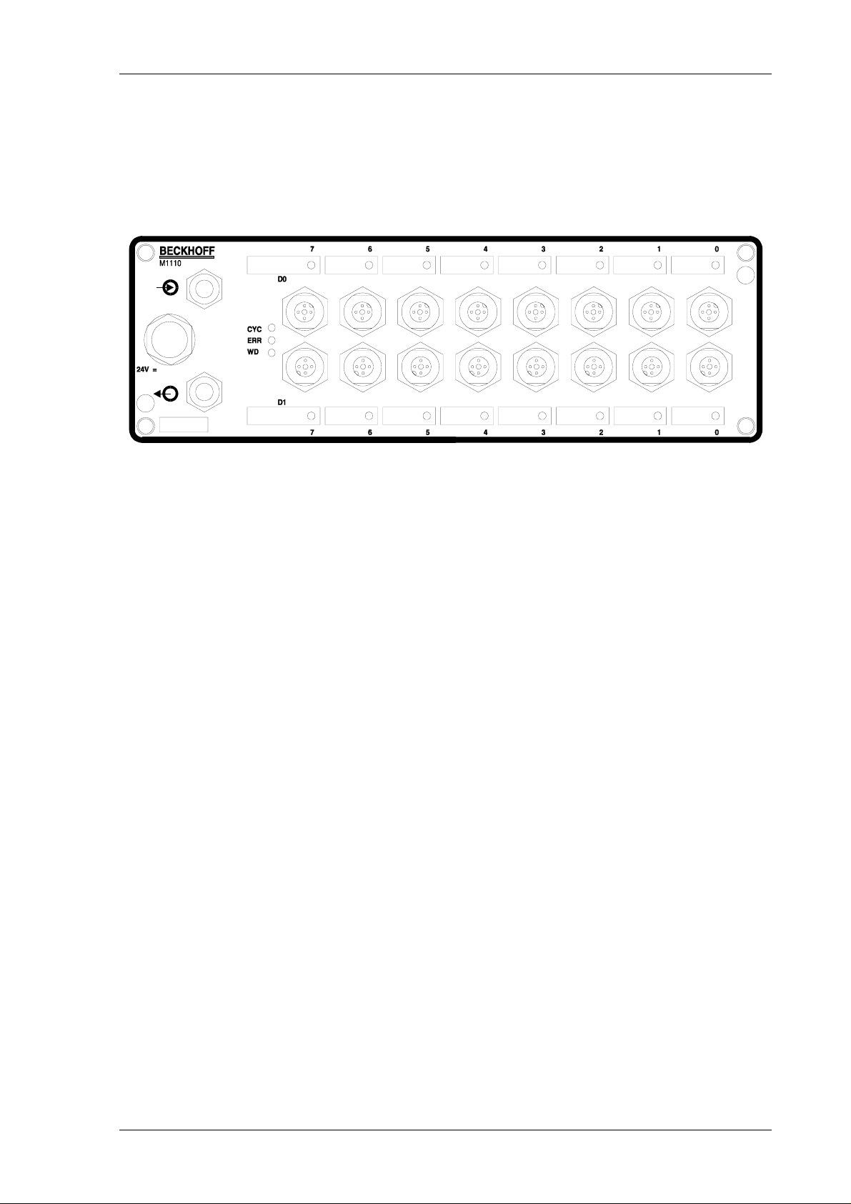
The parallel module M1110 is an input / output module used in the II/O system. There are 16
Standard 24 V inputs / outputs, which achieve 2 ports of 8 bit each.
These 2 ports ( D0,D1 ) correspond to the Data bytes in the FO transmissions protocol and
according to the way they are used, they can be configured as input or output.
Each input / output has a LED, that indicates the current state. In addition there are three
diagnosis LEDs for the II/O fibre optic ring:
LD1 The green ’CYCLE’ LED is switched on by each start bit of a telegram and is switched off
again by the stop bit.
LD2 The red ’ERROR’ LED is switched on after recognising a bad telegram (checksum, frame).
After a sequence of three correct telegrams (checksum, frame) were processed it is switched off
again.
LD3 The green LED ’WATCHDOG’ is switched on by a valid writing telegram with matching
address. If in a 100 ms afterwards no further telegram, which has the properties defined above, is
recognised a special unit of the module switches off all outputs.
The cartridge is according to IP65 protection norm designed as a compact, splash-proof and
dust proof box.
Date 09.03.93 Version 2.1 Page 3 of 17
Page 4
M1110 Parallel Input / Output Box Beckhoff II/O System
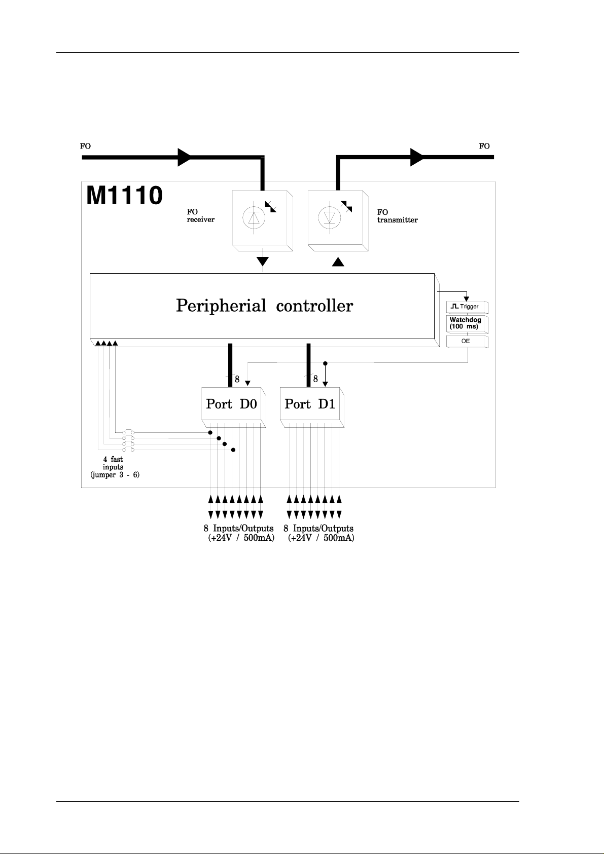
Basic Circuit Diagram
Page 4 of 17 Version 2.1 Date 09.03.93
Page 5

M1110 Parallel Input / Output Box Beckhoff II/O-System
2. Function Description Software
Date 09.03.93 Version 2.1 Page 5 of 17
Page 6

M1110 Parallel Input / Output Box Beckhoff II/O System
3. Technical Data
Inputs / Outputs
Input Specifications
input switching voltages
input delay
Output Specifications
Output Check
I / O Connections
Voltage Connection
Data Connection
16, can be configured for each port;
LED shows state of all inputs / outputs
24 V DC, 8 mA, digital filter
0 - 8V = LOW
15 - 24V = HIGH
0,7 ms RC network
6,8 ms input latch
24 V DC, max. 500 mA, short circuit proof
Watchdog System (100 ms)
round plug connectors according to
protection mode IP65 and to initiator norm
V1; +,-,Signal
Lumberg IP65 connector
Harting IP65 FO connector
Transmission Rate
Supply Voltage
Input Current
Cartridge
Protection mode
Size (W * H * D)
Working Temperature
Storage Temperature
2,5 MBaud, 25 µs for 32 Bit
24 V DC (± 10%)
0,1 A (without load and input currents)
Aluminium cartridge
IP65
80 * 250 * 52 mm
±0..+55 øC
-20..+70 øC
Page 6 of 17 Version 2.1 Date 09.03.93
Page 7

M1110 Parallel Input / Output Box Beckhoff II/O-System
4. Installation
The M1110 is connected externally to the fibre optic ring using fibre optic connections
(Harting , type F-TNC), or internally by Toshiba TOC P155. The maximum length of the FO
cable, leading to the neighbouring boxes, should not be more then 45 meters. These values are
only valid if for bending the cable a radius of at least 30 mm is used.
Common actors and sensors are connected directly to the inputs / outputs (using "+,-,signal" )
by round plug connectors according to initiator norm V1.
The installation of the M1110 is done at the machine. Sensors and actors can be connected to
the box directly.
Configuration
Each port of the M1110 can be, configured as input or as output. This does not dependent on
the configuration of the other ports. There are DIP switches used for configuration. The
switches are assigned as follows :
Switch 1 => Port D0
Switch 2 => Port D1
Switch 3 => *
Switch 4 => *
Depending on the state of the switches, the port is input or output :
’ON’ => port is output
’OFF’ => port is input
ATTENTION:
Configuring a port as input ( switch "OFF") all of the eight output controller
ICs of the port concerned have to be removed.
If the driver ICs are not removed the port is not functional as input, but the
module remains undamaged.
Date 09.03.93 Version 2.1 Page 7 of 17
Page 8

M1110 Parallel Input / Output Box Beckhoff II/O System
The following module configurations are possible by jumpers adjustments :
Jumper Field on board M1210_4
Jumper 1
If this jumper is set the ’Watchdog’ function is swit ched off.
This means if an error is detected the outputs set are not
switched off.
Jumper 2
The jumper is set according to the standard configuration.
The input signals are read each 6.8 msecs.
Jumper Field on Board M1110_4
Fast Inputs M1110_4 (Interrupt Inputs)
Jumper 3 Fast input II3 :
If jumper connection between port D0.3 and XILI NX II3 is
established.
Jumper 4 Fast input II2:
If jumper connection between port D0.2 and XILI NX II2 is
established.
Jumper 5 Fast input II1 :
If jumper connection between port D0.1 and XILI NX II1 is
established.
Jumper 6 Fast input II0 :
If jumper connection between port D0.0 and XILI NX II0 is
established.
Watchdog on / off
Latch on / off
Page 8 of 17 Version 2.1 Date 09.03.93
Page 9

M1110 Parallel Input / Output Box Beckhoff II/O-System
Power Supply
external
There is a three pole plug connection (Lumberg) for supply voltage with separate connections
for control logic / inputs (pin 1) and for outputs (pin 3) at same ground (pin 2).
internal
There is a three pole plug connection for supply voltage with separate connections for control
logic / inputs (+) and for outputs (A) at same ground (-).The plug-in card 1210 is
automatically connected to the supply voltage of the lower board if plugged in.
Date 09.03.93 Version 2.1 Page 9 of 17
Page 10

M1110 Parallel Input / Output Box Beckhoff II/O System
Page 10 of 17 Version 2.1 Date 09.03.93
Page 11

M1110 Parallel Input / Output Box Beckhoff II/O-System
Date 09.03.93 Version 2.1 Page 11 of 17
Page 12

M1110 Parallel Input / Output Box Beckhoff II/O System
5. Connection Table
Pin assignment (Cartridge)
Port D0 Port D1
Plug Pin Signal Plug Pin Signal
D00
D01
D02
D03
D04
D05
D06
D07
1
2
3
4
1
2
3
4
1
2
3
4
1
2
3
4
1
2
3
4
1
2
3
4
1
2
3
4
1
2
3
4
+24V
n.c.
GND
D0.0.
+24V
n.c.
GND
D0.1
+24V
n.c.
GND
D0.2
+24V
n.c.
GND
D0.3
+24V
n.c.
GND
D0.4
+24V
n.c.
GND
D0.5
+24V
n.c.
GND
D0.6
+24V
n.c.
GND
D0.7
D10
D11
D12
D13
D14
D15
D16
D17
1
2
3
4
1
2
3
4
1
2
3
4
1
2
3
4
1
2
3
4
1
2
3
4
1
2
3
4
1
2
3
4
+24V
n.c.
GND
D1.0
+24V
n.c.
GND
D1.1
+24V
n.c.
GND
D1.2
+24V
n.c.
GND
D1.3
+24V
n.c.
GND
D1.4
+24V
n.c.
GND
D1.5
+24V
n.c.
GND
D1.6
+24V
n.c.
GND
D1.1
Page 12 of 17 Version 2.1 Date 09.03.93
Page 13

M1110 Parallel Input / Output Box Beckhoff II/O-System
Pin assignment (Board)
Internal Power Supply (Board)
Power Supply Connection
Pin Signal Description
+ +24V + 24 V Control power supply for IC’s
and Inputs
- GND Ground for + and A
A +24V + 24 V power supply for outputs
External Power Supply ( plug-in connector Lumberg)
Date 09.03.93 Version 2.1 Page 13 of 17
Page 14

M1110 Parallel Input / Output Box Beckhoff II/O System
Signal Description
Pin Signal I/O Description
D07-1 +24V - +24VDC support voltage
D07-2 n.c. - not connected
D07-3 GND - GND support voltage
D07-4 D0.7 I/O Bit 7 of data byte 0
D0.7 is output,
if DIL_switch S1 = ON
D0.7 is input,
if DIL_switch S1 = OFF
D06-1 +24V - +24VDC support voltage
D06-2 n.c. - not connected
D06-3 GND - GND support voltage
D06-4 D0.6 I/O Bit 6 of data byte 0
D0.6 is output,
if DIL_switch S1 = ON
D0.6 is input,
if DIL_switch S1 = OFF
D05-1 +24V - +24VDC support voltage
D05-2 n.c. - not connected
D05-3 GND - GND support voltage
D05-4 D0.5 I/O Bit 5 of data byte 0
D0.5 is output,
if DIL_switch S1 = ON
D0.5 is input,
if DIL_switch S1 = OFF
D04-1 +24V - +24VDC support voltage
D04-2 n.c. - not connected
D04-3 GND - GND support voltage
D04-4 D0.4 I/O Bit 4 of data byte 0
D0.4 is output,
if DIL_switch S1 = ON
D0.4 is input,
if DIL_switch S1 = OFF
D03-1 +24V - +24VDC support voltage
D03-2 n.c. - not connected
D03-3 GND - GND support voltage
D03-4 D0.3 I/O Bit 3 of data byte 0
D0.3 is output,
if DIL_switch S1 = ON
D0.3 is input,
if DIL_switch S1 = OFF
D02-1 +24V - +24VDC support voltage
D02-2 n.c. - not connected
D02-3 GND - GND support voltage
Page 14 of 17 Version 2.1 Date 09.03.93
Page 15

M1110 Parallel Input / Output Box Beckhoff II/O-System
Pin Signal I/O Description
D02-4 D0.2 I/O Bit 2 of data byte 0
D0.2 is output,
if DIL_switch S1 = ON
D0.2 is input,
if DIL_switch S1 = OFF
D01-1 +24V - +24VDC support voltage
D01-2 n.c. - not connected
D01-3 GND - GND support voltage
D01-4 D0.1 I/O Bit 1 of data byte 0
D0.1 is output,
if DIL_switch S1 = ON
D0.1 is input,
if DIL_switch S1 = OFF
D00-1 +24V - +24VDC support voltage
D00-2 n.c. - not connected
D00-3 GND - GND support voltage
D00-4 D0.0 I/O Bit 0 of data byte 0
D0.0 is output,
if DIL_switch S1 = ON
D0.0 is input,
if DIL_switch S1 = OFF
Date 09.03.93 Version 2.1 Page 15 of 17
Page 16

M1110 Parallel Input / Output Box Beckhoff II/O System
Pin Signal I/O Description
D17-1 +24V - +24VDC support voltage
D17-2 n.c. - not connected
D17-3 GND - GND support voltage
D17-4 D1.7 I/O Bit 7 of data byte 0
D1.7 is output,
if DIL_switch S2 = ON
D1.7 is input,
if DIL_switch S2 = OFF
D16-1 +24V - +24VDC support voltage
D16-2 n.c. - not connected
D16-3 GND - GND support voltage
D16-4 D1.6 I/O Bit 6 of data byte 0
D1.6 is output,
if DIL_switch S2 = ON
D1.6 is input,
if DIL_switch S2 = OFF
D15-1 +24V - +24VDC support voltage
D15-2 n.c. - not connected
D15-3 GND - GND support voltage
D15-4 D1.5 I/O Bit 5 of data byte 0
D1.5 is output,
if DIL_switch S2 = ON
D1.5 is input,
if DIL_switch S2 = OFF
D14-1 +24V - +24VDC support voltage
D14-2 n.c. - not connected
D14-3 GND - GND support voltage
D14-4 D1.4 I/O Bit 4 of data byte 0
D1.4 is output,
if DIL_switch S2 = ON
D1.4 is input,
if DIL_switch S2 = OFF
D13-1 +24V - +24VDC support voltage
D13-2 n.c. - not connected
D13-3 GND - GND support voltage
D13-4 D1.3 I/O Bit 3 of data byte 0
D1.3 is output,
if DIL_switch S2 = ON
D1.3 is input,
if DIL_switch S2 = OFF
D12-1 +24V - +24VDC support voltage
D12-2 n.c. - not connected
D12-3 GND - GND support voltage
Page 16 of 17 Version 2.1 Date 09.03.93
Page 17

M1110 Parallel Input / Output Box Beckhoff II/O-System
Pin Signal I/O Description
D12-4 D1.2 I/O Bit 2 of data byte 0
D1.2 is output,
if DIL_switch S2 = ON
D1.2 is input,
if DIL_switch S2 = OFF
D11-1 +24V - +24VDC support voltage
D11-2 n.c. - not connected
D11-3 GND - GND support voltage
D11-4 D1.1 I/O Bit 1 of data byte 0
D1.1 is output,
if DIL_switch S2 = ON
D1.1 is input,
if DIL_switch S2 = OFF
D10-1 +24V - +24VDC support voltage
D10-2 n.c. - not connected
D10-3 GND - GND support voltage
D10-4 D1.0 I/O Bit 0 of data byte 0
D1.0 is output,
if DIL_switch S2 = ON
D1.0 is input,
if DIL_switch S2 = OFF
Date 09.03.93 Version 2.1 Page 17 of 17
 Loading...