

Page 1

Documentation
EP4174-0002
EtherCAT Box with configurable analog outputs
Version:
Date:
1.1.0
2018-12-06
Page 2

Page 3

Table of contents
Table of contents
1 Foreword ....................................................................................................................................................5
1.1 Notes on the documentation..............................................................................................................5
1.2 Safety instructions .............................................................................................................................6
1.3 Documentation issue status ..............................................................................................................7
2 Product overview.......................................................................................................................................8
2.1 EtherCAT Box - Introduction..............................................................................................................8
2.2 EP4174-0002 - Introduction.............................................................................................................10
2.3 EP4174-0002 - Technical data ........................................................................................................11
2.4 EP4174 - Status LEDs.....................................................................................................................12
2.5 EP4174-0002 - Process image........................................................................................................13
3 Mounting and connection.......................................................................................................................14
3.1 Mounting..........................................................................................................................................14
3.1.1 Dimensions ...................................................................................................................... 14
3.1.2 Fixing ............................................................................................................................... 15
3.1.3 Nut torque for connectors ................................................................................................ 16
3.1.4 Additional checks............................................................................................................. 17
3.2 Connection ......................................................................................................................................18
3.2.1 EtherCAT connection....................................................................................................... 18
3.2.2 EtherCAT - Fieldbus LEDs .............................................................................................. 20
3.2.3 Power Connection ........................................................................................................... 21
3.2.4 Power cables ................................................................................................................... 24
3.2.5 Power cable conductor losses M8 ................................................................................... 26
3.2.6 EP4174-0002 - Signal connection ................................................................................... 27
3.3 UL Requirements.............................................................................................................................28
3.4 ATEX notes .....................................................................................................................................30
3.4.1 ATEX - Special conditions ............................................................................................... 30
3.4.2 BG2000-0000 - EtherCAT Box protection enclosure....................................................... 31
3.4.3 ATEX Documentation ...................................................................................................... 32
4 Commissioning/Configuration ...............................................................................................................33
4.1 Inserting into the EtherCAT network................................................................................................33
4.2 Configuration via TwinCAT..............................................................................................................36
4.3 Object overview ...............................................................................................................................44
4.4 Object description and parameterization .........................................................................................47
4.4.1 Objects to be parameterized during commissioning........................................................ 47
4.4.2 Objects for regular operation ........................................................................................... 52
4.4.3 Standard objects (0x1000-0x1FFF) ................................................................................. 52
4.4.4 Profile-specific objects (0x6000-0xFFFF) ........................................................................ 55
4.5 Restoring the delivery state .............................................................................................................57
5 Appendix ..................................................................................................................................................59
5.1 General operating conditions...........................................................................................................59
5.2 EtherCAT Box- / EtherCATPBox - Accessories ............................................................................60
5.3 Support and Service ........................................................................................................................61
EP4174-0002 3Version: 1.1.0
Page 4

Table of contents
EP4174-00024 Version: 1.1.0
Page 5

Foreword
1 Foreword
1.1 Notes on the documentation
Intended audience
This description is only intended for the use of trained specialists in control and automation engineering who
are familiar with the applicable national standards.
It is essential that the documentation and the following notes and explanations are followed when installing
and commissioning these components.
It is the duty of the technical personnel to use the documentation published at the respective time of each
installation and commissioning.
The responsible staff must ensure that the application or use of the products described satisfy all the
requirements for safety, including all the relevant laws, regulations, guidelines and standards.
Disclaimer
The documentation has been prepared with care. The products described are, however, constantly under
development.
We reserve the right to revise and change the documentation at any time and without prior announcement.
No claims for the modification of products that have already been supplied may be made on the basis of the
data, diagrams and descriptions in this documentation.
Trademarks
Beckhoff®, TwinCAT®, EtherCAT®, EtherCATP®, SafetyoverEtherCAT®, TwinSAFE®, XFC® and XTS® are
registered trademarks of and licensed by Beckhoff Automation GmbH.
Other designations used in this publication may be trademarks whose use by third parties for their own
purposes could violate the rights of the owners.
Patent Pending
The EtherCAT Technology is covered, including but not limited to the following patent applications and
patents: EP1590927, EP1789857, DE102004044764, DE102007017835 with corresponding applications or
registrations in various other countries.
The TwinCAT Technology is covered, including but not limited to the following patent applications and
patents: EP0851348, US6167425 with corresponding applications or registrations in various other countries.
EtherCAT® is registered trademark and patented technology, licensed by Beckhoff Automation GmbH,
Germany.
Copyright
© Beckhoff Automation GmbH & Co. KG, Germany.
The reproduction, distribution and utilization of this document as well as the communication of its contents to
others without express authorization are prohibited.
Offenders will be held liable for the payment of damages. All rights reserved in the event of the grant of a
patent, utility model or design.
EP4174-0002 5Version: 1.1.0
Page 6
Foreword
1.2 Safety instructions
Safety regulations
Please note the following safety instructions and explanations!
Product-specific safety instructions can be found on following pages or in the areas mounting, wiring,
commissioning etc.
Exclusion of liability
All the components are supplied in particular hardware and software configurations appropriate for the
application. Modifications to hardware or software configurations other than those described in the
documentation are not permitted, and nullify the liability of Beckhoff Automation GmbH & Co. KG.
Personnel qualification
This description is only intended for trained specialists in control, automation and drive engineering who are
familiar with the applicable national standards.
Description of instructions
In this documentation the following instructions are used.
These instructions must be read carefully and followed without fail!
DANGER
Serious risk of injury!
Failure to follow this safety instruction directly endangers the life and health of persons.
WARNING
Risk of injury!
Failure to follow this safety instruction endangers the life and health of persons.
CAUTION
Personal injuries!
Failure to follow this safety instruction can lead to injuries to persons.
NOTE
Damage to environment/equipment or data loss
Failure to follow this instruction can lead to environmental damage, equipment damage or data loss.
Tip or pointer
This symbol indicates information that contributes to better understanding.
EP4174-00026 Version: 1.1.0
Page 7

Foreword
1.3 Documentation issue status
Version Modifications
1.1.0 • Update Safety instructions
• Correction chapter Power cable
• Update chapter Mounting
1.0.0 • Migration
0.5 • First preliminary version
Firmware and hardware versions
This documentation refers to the firmware and hardware version that was applicable at the time the
documentation was written.
The module features arecontinuously improved and developed further. Modules having earlier production
statuses cannot have the same properties as modules with the latest status. However, existing properties
are retained and are not changed, so that older modules can always be replaced with new ones.
Documentation
Version
1.1.0 02 11
1.0.0 02 10
0.5 01 00
The firmware and hardware version (delivery state) can be found in the serial number printed on the side of
the EtherCATBox.
Syntax of the serial number
Structure of the serial number: WWYYFFHH
WW - week of production (calendar week)
YY - year of production
FF - firmware version
HH - hardware version
Example with ser. no.: 55 09 01 00:
55 - week of production 55
09 - year of production 2009
01 - firmware version 01
00 - hardware version 01
EP4174-0002
Firmware Hardware
EP4174-0002 7Version: 1.1.0
Page 8

Product overview
2 Product overview
2.1 EtherCAT Box - Introduction
The EtherCAT system has been extended with EtherCAT Box modules with protection class IP67. Through
the integrated EtherCAT interface the modules can be connected directly to an EtherCAT network without an
additional Coupler Box. The high-performance of EtherCAT is thus maintained into each module.
The extremely low dimensions of only 126x30x26.5 mm (hxw xd) are identical to those of the Fieldbus
Box extension modules. They are thus particularly suitable for use where space is at a premium. The small
mass of the EtherCAT modules facilitates applications with mobile I/O interface (e.g. on a robot arm). The
EtherCAT connection is established via screened M8connectors.
Fig.1: EtherCAT Box Modules within an EtherCAT network
The robust design of the EtherCAT Box modules enables them to be used directly at the machine. Control
cabinets and terminal boxes are now no longer required. The modules are fully sealed and therefore ideally
prepared for wet, dirty or dusty conditions.
Pre-assembled cables significantly simplify EtherCAT and signal wiring. Very few wiring errors are made, so
that commissioning is optimized. In addition to pre-assembled EtherCAT, power and sensor cables, fieldconfigurable connectors and cables are available for maximum flexibility. Depending on the application, the
sensors and actuators are connected through M8 or M12connectors.
The EtherCAT modules cover the typical range of requirements for I/O signals with protection class IP67:
• digital inputs with different filters (3.0ms or 10μs)
• digital outputs with 0.5 or 2A output current
• analog inputs and outputs with 16bit resolution
• Thermocouple and RTD inputs
• Stepper motor modules
XFC (eXtreme Fast Control Technology) modules, including inputs with time stamp, are also available.
EP4174-00028 Version: 1.1.0
Page 9
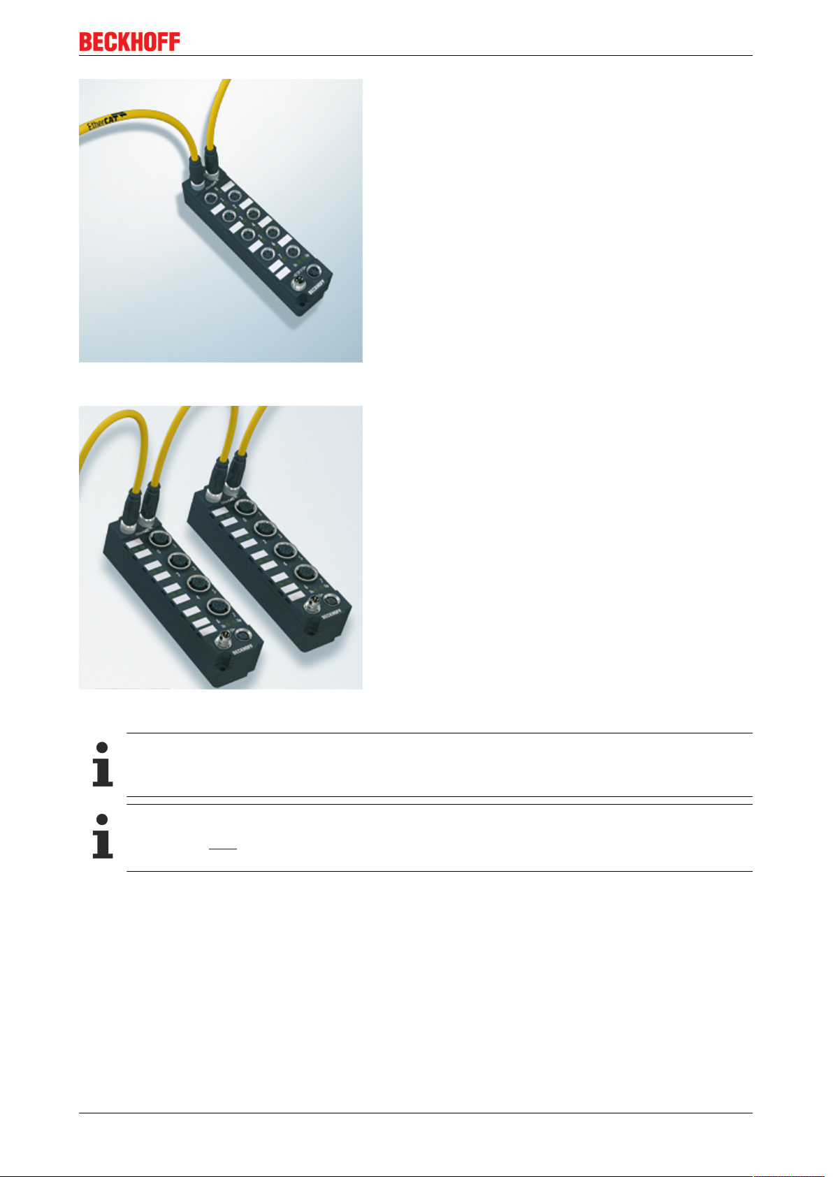
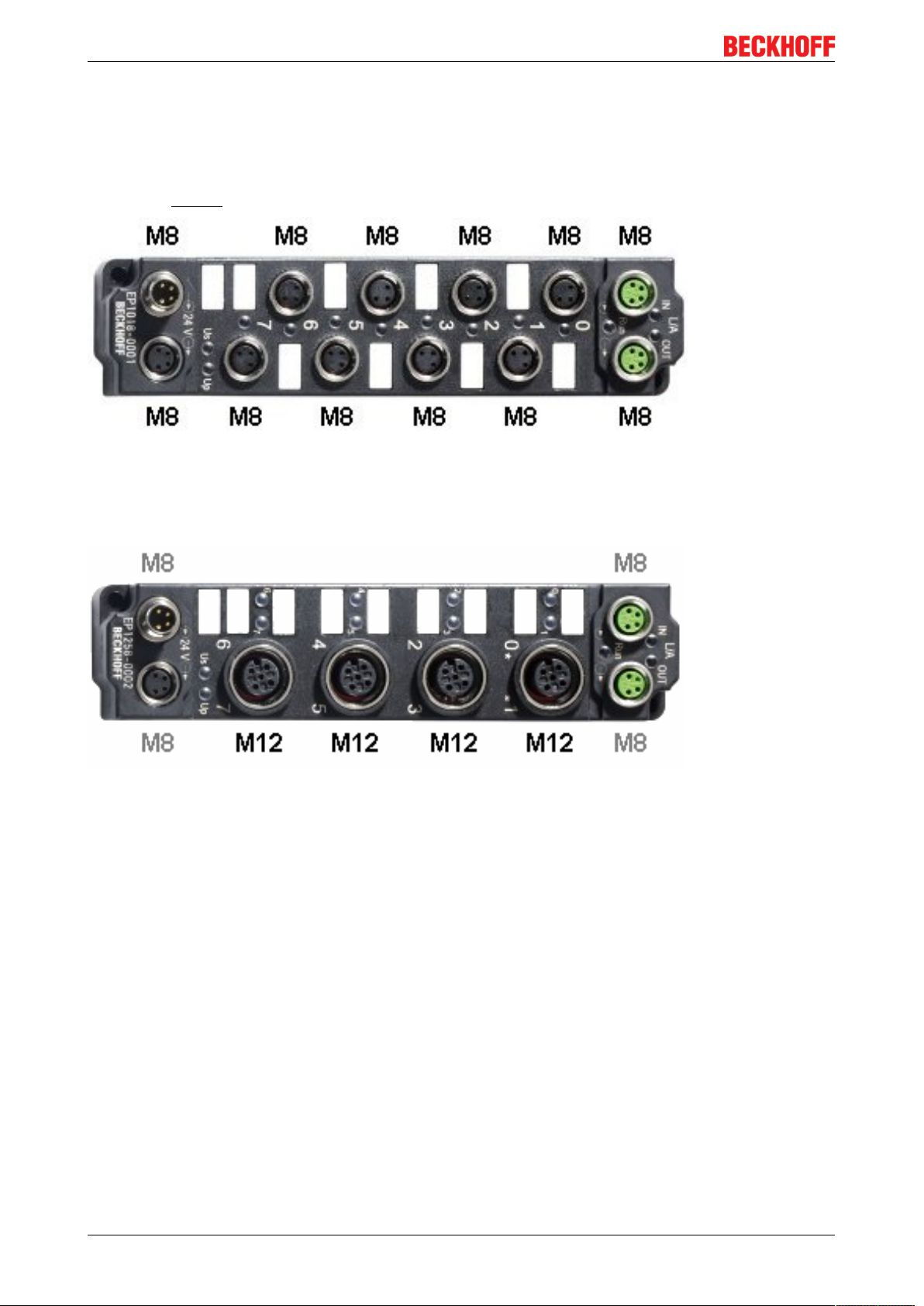
Fig.2: EtherCAT Box with M8 connections for sensors/actuators
Product overview
Fig.3: EtherCAT Box with M12 connections for sensors/actuators
Basic EtherCAT documentation
You will find a detailed description of the EtherCAT system in the Basic System Documentation for
EtherCAT, which is available for download from our website (www.beckhoff.com) under Downloads.
EtherCAT XML Device Description
You will find XML files (XML Device Description Files) for Beckhoff EtherCAT modules on our website (www.beckhoff.com) under Downloads, in the Configuration Files area.
EP4174-0002 9Version: 1.1.0
Page 10

Product overview
2.2 EP4174-0002 - Introduction
Fig.4: EP4174-0002
EtherCAT Box with four configurable analog outputs
The EP4174-0002 EtherCAT Box has four analog outputs which can be individually parameterized, so that
they generate signals either in the -10 to +10V range or the 0/4…20mA range.
The voltage or output current is fed to the process level, electrically isolated with a resolution of 15bit
(default). The output scaling can be changed if required.
Ground potential for the four output channels is common with the 24VDC supply. The analog actuators are
fed from the load voltage (freely selectable up to 30VDC). The applied load voltage is available for supplying
actuators in further EtherCAT Box modules.
EP4174-000210 Version: 1.1.0
Page 11

Product overview
2.3 EP4174-0002 - Technical data
Technical data EP4174-0002
Fieldbus EtherCAT
Fieldbus connection 2 x M8 socket (green)
Number of outputs 4
Connection outputs [}27]
Signal type Configurable:
Load > 5kΩ | <500Ω
Resolution 16bit (including sign)
Conversion time <4ms
Measuring error < 0,1% (relative to full scale value)
Supply of the module circuitry From the control voltage Us
Current consumption of the module circuitry typically 120mA
Sensor supply from load supply voltage Up, DC, any value up to 30V
Power supply connection Power supply: 1 x M8 plug, 4-pin
Process image Outputs: 4 x 16bit
Electrical isolation Control voltage/ fieldbus: yes
Permissible ambient temperature during
operation
Permissible ambient temperature during
storage
Vibration/ shock resistance conforms to EN60068-2-6/ EN60068-2-27
EMC immunity/ emission conforms to EN61000-6-2/ EN61000-6-4
Protection class IP65, IP66, IP67 (according to EN 60529)
Approvals
Installation position variable
M12 sockets
0…+10V
-10…+10V
0…20mA
4…20mA
Onward connection: 1 x M8 socket, 4-pin
-25°C ... +60°C
0°C ... +55 °C (according to cULus, see UL requirements
[}28])
0°C ... +55°C (according to ATEX, see special conditions
[}30])
-25°C ... +85°C
CE, cULus [}28], ATEX [}30]
EP4174-0002 11Version: 1.1.0
Page 12

Product overview
2.4 EP4174 - Status LEDs
Fig.5: EP4174 LEDs
Status LEDs at the M12 connections
Connection LED Display Meaning
M12 socket no. 1-4 R
left
E
right
Power supply
LED Display Meaning
Us off the power supply voltage, Us, is not present
green illuminated the power supply voltage, Us, is present
Up off the power supply voltage, Up, is not present
green illuminated The power supply voltage, Up, is present
off No data transfer to the D/A converter
green Data transfer to the D/A converter
off Function OK
red Error: Broken wire or measured value outside the measuring
range
EP4174-000212 Version: 1.1.0
Page 13
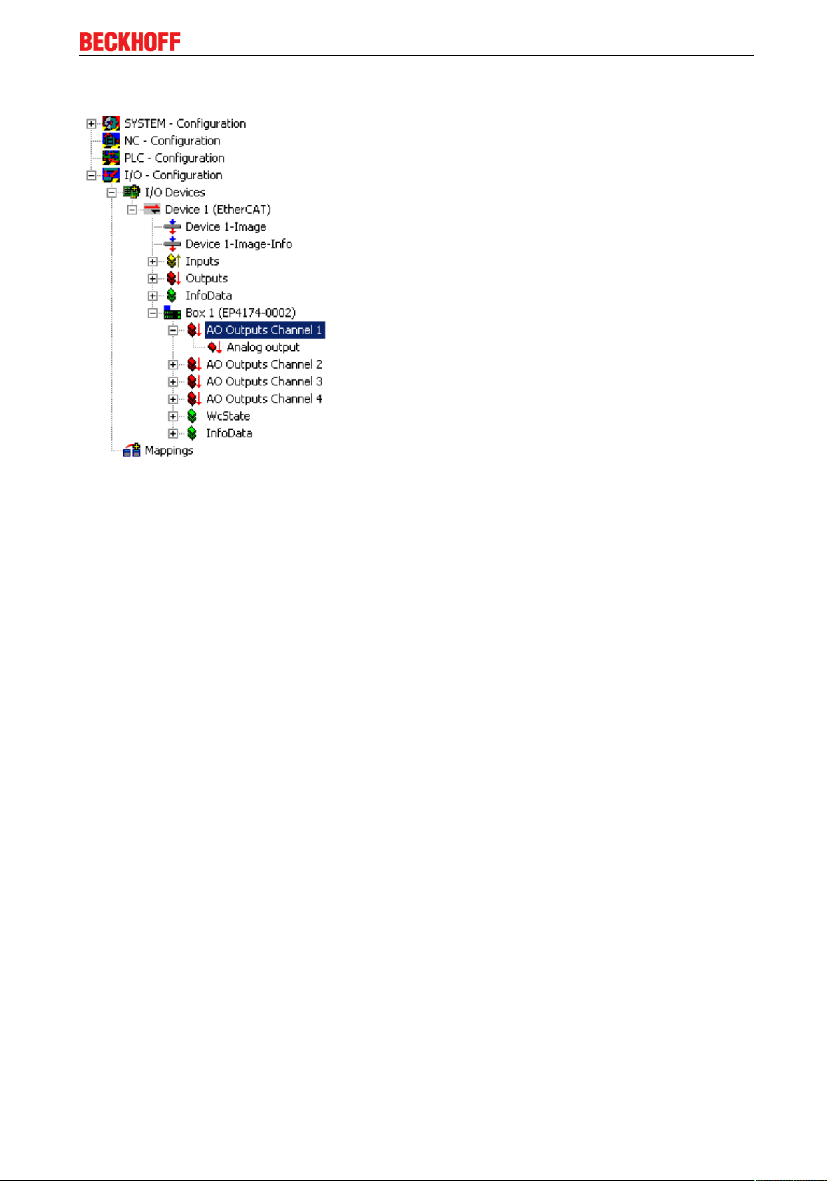
2.5 EP4174-0002 - Process image
Product overview
Fig.6: EP4174-0002 - Process image
AO Outputs Channel1
The data for the first analog channel can be found under AO Outputs Channel1.
AO Outputs Channel2 to 4
The data of analog channels 2 to 4 have the same structure as those of the first channel.
EP4174-0002 13Version: 1.1.0
Page 14
Mounting and connection
3 Mounting and connection
3.1 Mounting
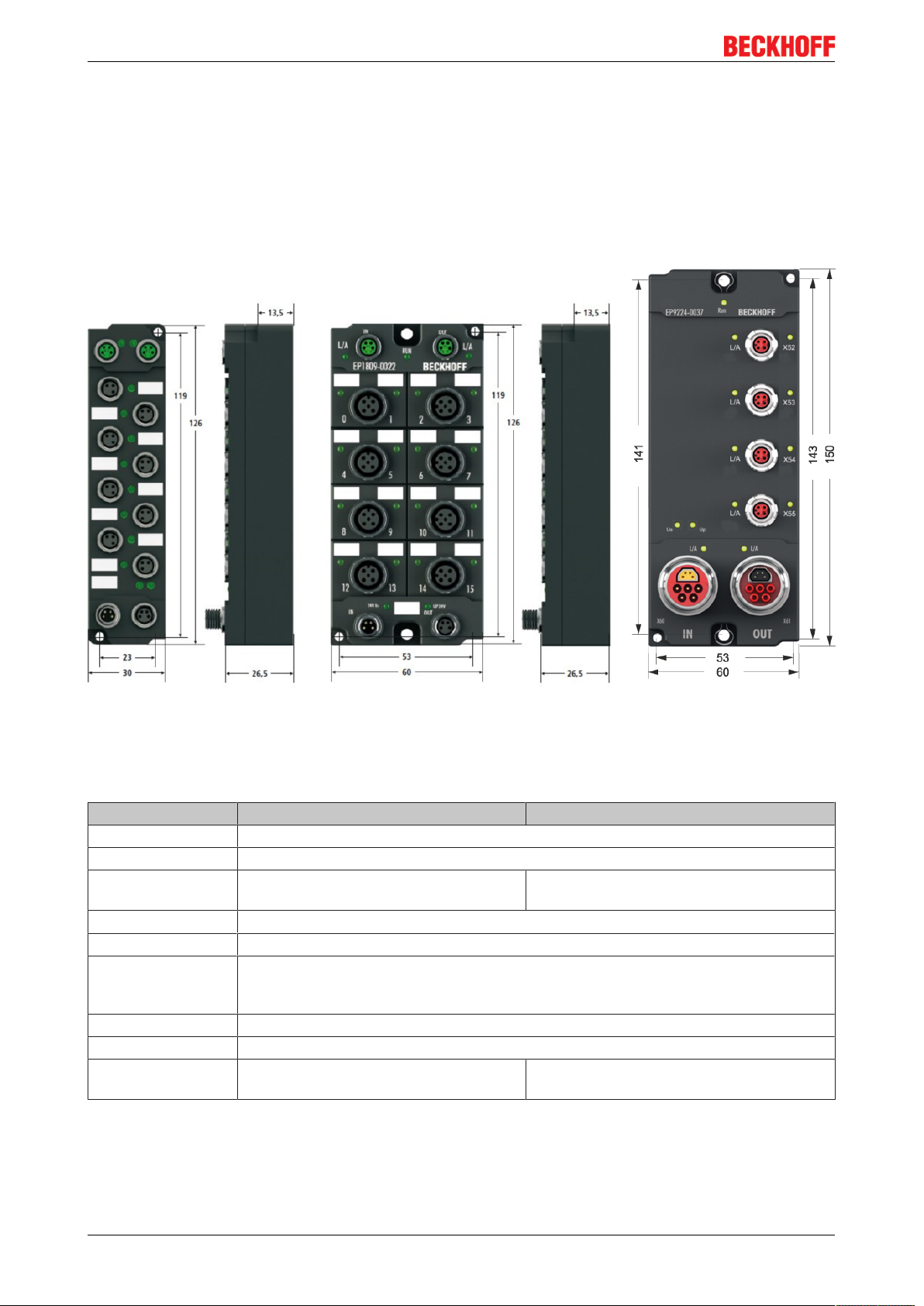
3.1.1 Dimensions
Fig.7: Dimensions of the EtherCAT Box Modules
All dimensions are given in millimeters.
Housing properties
EtherCAT Box lean body wide bodies
Housing material PA6 (polyamide)
Casting compound Polyurethane
Mounting two fastening holes Ø3mm for M3 two fastening holes Ø3mm for M3
two fastening holes Ø4.5mm for M4
Metal parts Brass, nickel-plated
Contacts CuZn, gold-plated
Power feed through max. 4A (M8)
max. 16A (7/8“)
max. 15.5A (B17 5G 1.5mm2)
Installation position variable
Protection class IP65, IP66, IP67 (conforms to EN 60529) when screwed together
Dimensions
(HxWxD)
app. 126 x 30 x 26.5mm app. 126 x 60 x 26,5mm
app. 150 x 60 x 26.5mm (without 7/8", B17)
EP4174-000214 Version: 1.1.0
Page 15
Mounting and connection
3.1.2 Fixing
Note or pointer
While mounting the modules, protect all connectors, especially the IP-Link, against contamination!
Only with connected cables or plugs the protection class IP67 is guaranteed! Unused connectors
have to be protected with the right plugs! See for plug sets in the catalogue.
Modules with narrow housing are mounted with two M3 bolts.
Modules with wide housing are mounted with two M3 bolts to the fixing holes located at the corners or
mounted with two M4 bolts to the fixing holes located centrally.
The bolts must be longer than 15 mm. The fixing holes of the modules are not threaded.
When assembling, remember that the fieldbus connectors increases the overall height. See chapter
accessories.
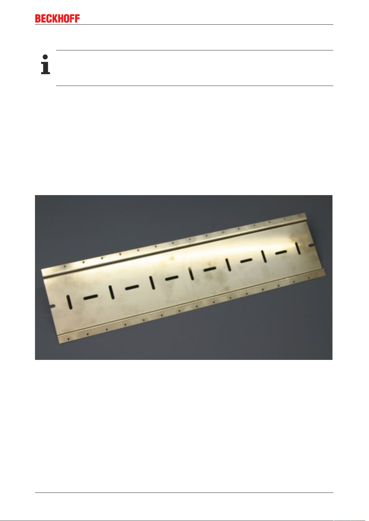
Mounting Rail ZS5300-0001
The mounting rail ZS5300-0001 (500 mm x 129 mm) allows the time saving assembly of modules.
The rail is made of stainless steel, 1.5 mm thick, with already pre-made M3 threads for the modules. The rail
has got 5.3 mm slots to mount it via M5 screws to the machine.
Fig.8: Mounting Rail ZS5300-000
The mounting rail is 500 mm long, that way 15 narrow modules can be mounted with a distance of 2 mm
between two modules. The rail can be cut to length for the application.
Mounting Rail ZS5300-0011
The mounting rail ZS5300-0011 (500 mm x 129 mm) has in addition to the M3 treads also pre-made M4
treads to fix 60 mm wide modules via their middle holes.
Up to 14 narrow or 7 wide modules may be mixed mounted.
EP4174-0002 15Version: 1.1.0
Page 16
Mounting and connection
3.1.3 Nut torque for connectors
M8 connectors
It is recommended to pull the M8 connectors tight with a nut torque of 0.4 Nm. When using the torque control
screwdriver ZB8800 is also a max. torque of 0.5Nm permissible.
Fig.9: EtherCAT Box with M8 connectors
M12 connectors
It is recommended to pull the M12 connectors tight with a nut torque of 0.6 Nm.
Fig.10: EtherCAT Box with M8 and M12 connectors
EP4174-000216 Version: 1.1.0
Page 17
7/8" plug connectors
We recommend fastening the 7/8" plug connectors with a torque of 1.5Nm.
Fig.11: 7/8" plug connectors
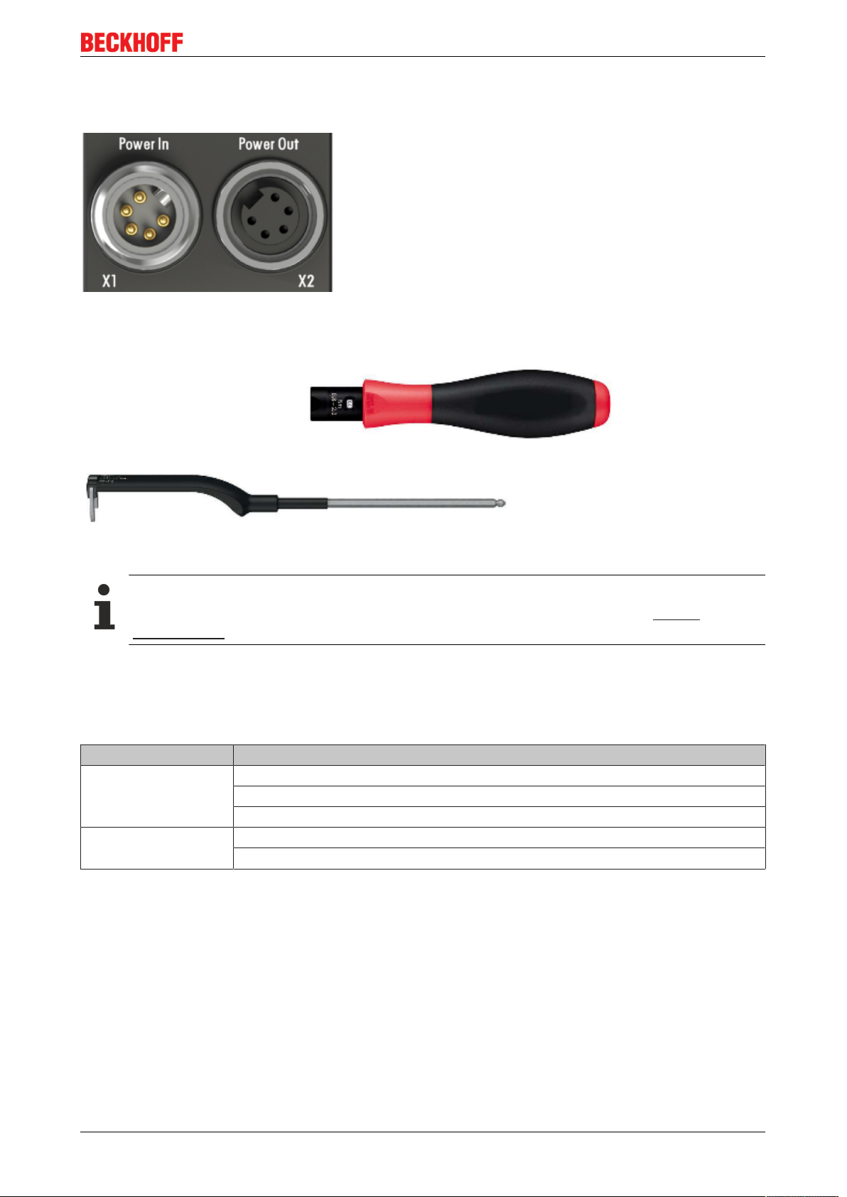
Torque socket wrenches
Mounting and connection
Fig.12: ZB8801 torque socket wrench
Ensure the right torque
Use the torque socket wrenches available by Beckhoff to pull the connectors tight (ZB8800,
ZB8801-0000)!
3.1.4 Additional checks
The boxes have undergone the following additional tests:
Verification Explanation
Vibration 10 frequency runs in 3 axes
5Hz < f < 60Hz displacement 0.35mm, constant amplitude
60.1Hz < f < 500Hz acceleration 5g, constant amplitude
Shocks 1000 shocks in each direction, in 3 axes
35g, 11ms
EP4174-0002 17Version: 1.1.0
Page 18
Mounting and connection
3.2 Connection
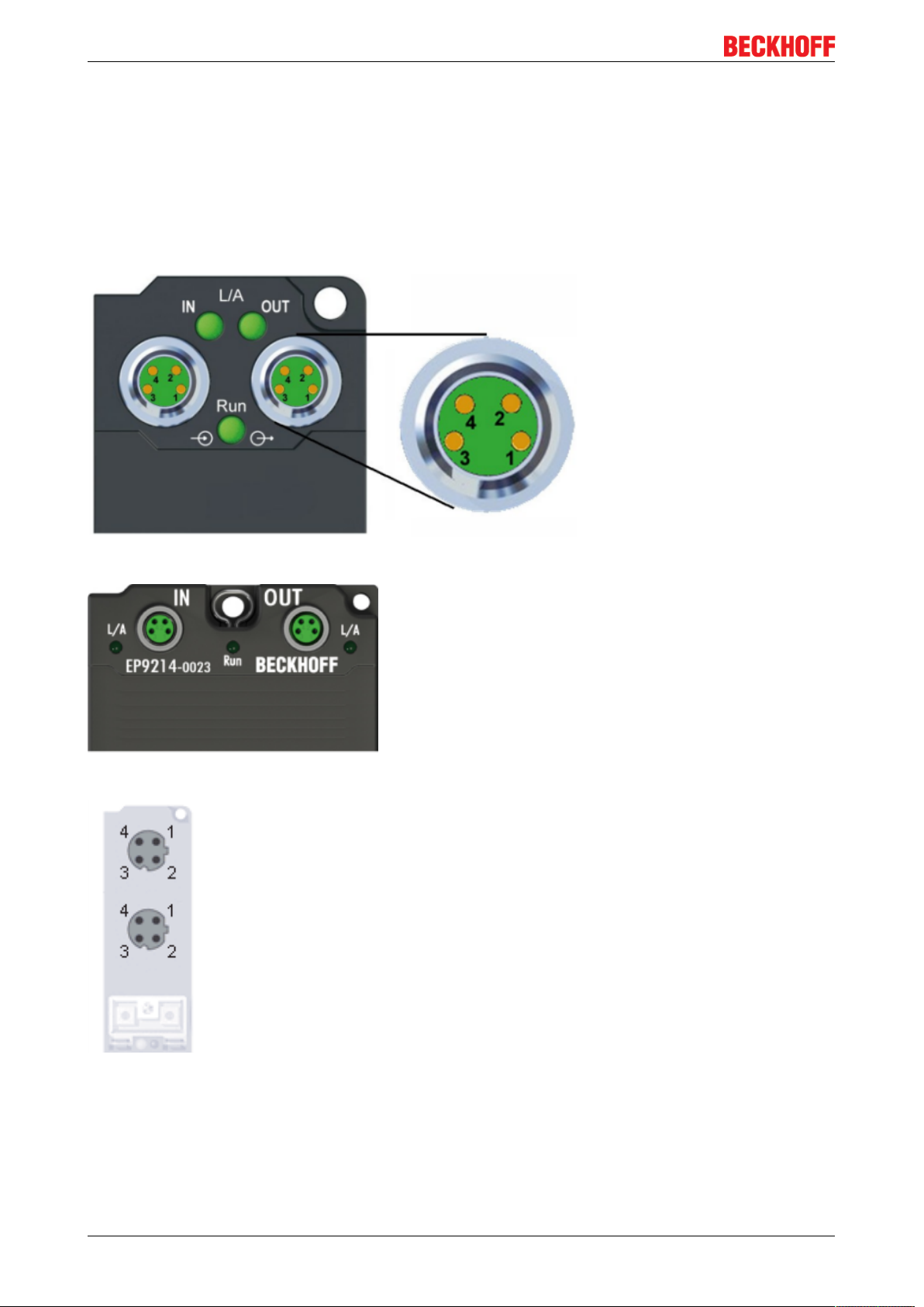
3.2.1 EtherCAT connection
For the incoming and ongoing EtherCAT connection,
• the EtherCAT Box (EPxxxx) has two M8 sockets, marked in green
• the Coupler Box (FBB-x110) has two M12 sockets
Fig.13: EtherCAT Box: M8, 30mm housing
Fig.14: EtherCAT Box: M860mm housing (example: EP9214)
Fig.15: Coupler Box: M12
Assignment
There are various different standards for the assignment and colors of connectors and cables for Ethernet/
EtherCAT.
EP4174-000218 Version: 1.1.0
Page 19

Mounting and connection
Ethernet/EtherCAT Plug connector Cable Standard
Signal Description M8 M12 RJ45
Tx + Transmit Data+ Pin 1 Pin 1 Pin 1 yellow
Tx - Transmit Data- Pin 4 Pin 3 Pin 2 orange
Rx + Receive Data+ Pin 2 Pin 2 Pin 3 white
Rx - Receive Data- Pin 3 Pin 4 Pin 6 blue
Shield Shield Housing Shroud Screen Screen Screen
1
) colored markings according to EN 61918 in the four-pin RJ45 connector ZS1090-0003
2
) wire colors according to EN 61918
3
) wire colors
1
ZB9010, ZB9020,
ZB9030, ZB9032,
ZK1090-6292,
ZK1090-3xxx-xxxx
2
2
2
2
ZB9031 and old versions
of ZB9030, ZB9032,
ZK1090-3xxx-xxxx
orange/white
orange
blue/white
3
blue
3
3
3
TIA-568B
white/orange
orange
white/green
green
Assimilation of color coding for cable ZB9030, ZB9032 and ZK1090-3xxxx-xxxx (with
M8 connectors)
For unification the prevalent cables ZB9030, ZB9032 and ZK1090-3xxx-xxxx this means the pre assembled cables with M8 connectors were changed to the colors of EN61918 (yellow, orange, white,
blue).So different color coding exists. But the electrical properties are absolutely identical.
EtherCAT connector
The following connectors can be supplied for use in Beckhoff EtherCAT systems.
Name Connector Comment
ZS1090-0003 RJ45 four-pole, IP20, field-configurable
ZS1090-0004 M12, male four-pin, IP67, for field assembly
ZS1090-0005 RJ45 eight-pole, IP20, field-configurable, suitable for gigabit Ethernet
ZS1090-0006 M8 plug connector four-pole, IP67, field-configurable, for cable type ZB903x
ZS1090-0007 M8 socket four-pole, IP67, field-configurable, for cable type ZB903x
ZS1090-1006 M8 plug connector four-pole, IP67, field-configurable up to OD=6.5mm
ZS1090-1007 M8 socket four-pole, IP67, field-configurable up to OD=6.5mm
EP4174-0002 19Version: 1.1.0
Page 20
Mounting and connection
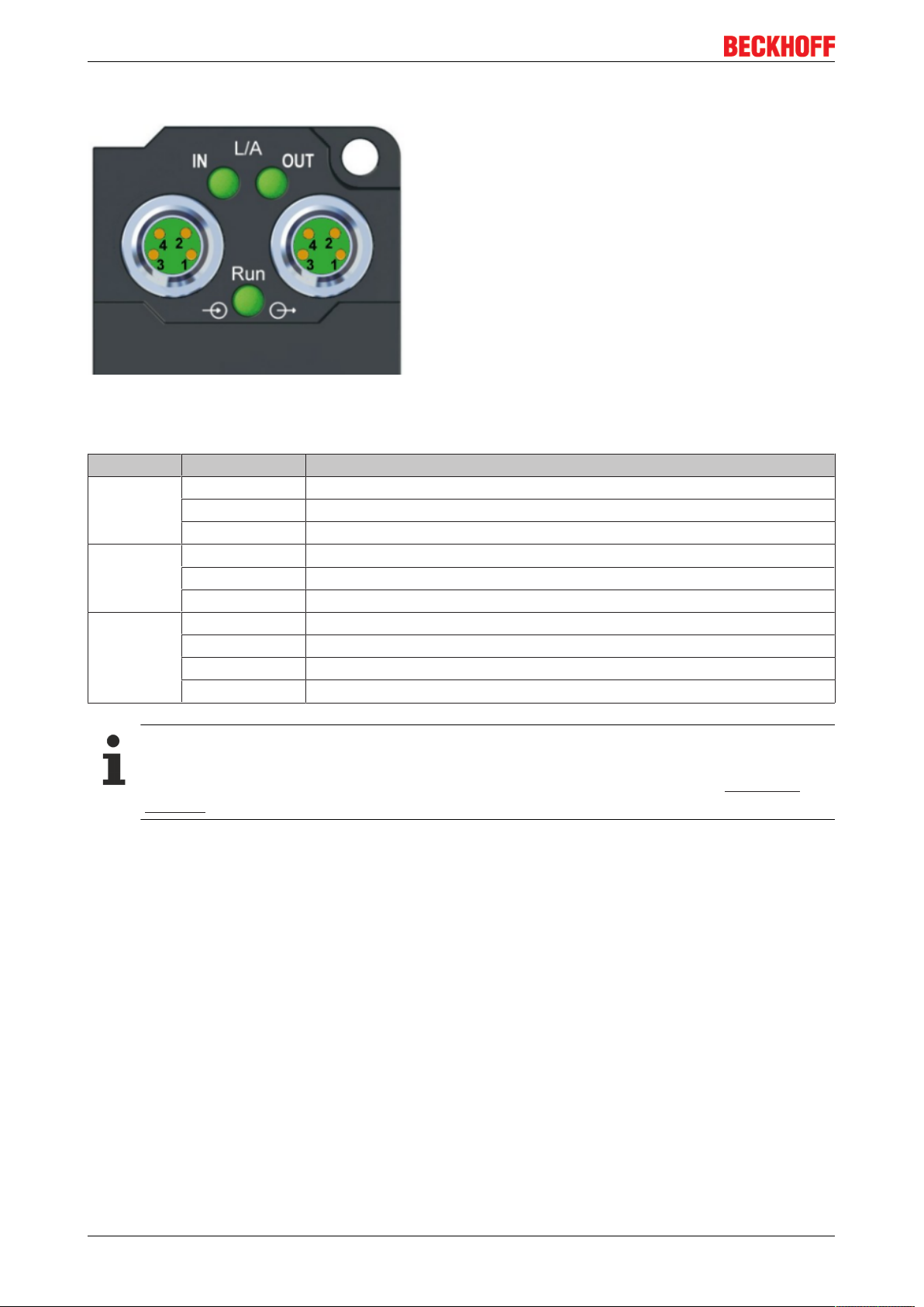
3.2.2 EtherCAT - Fieldbus LEDs
Fig.16: EtherCAT-LEDs
LED display
LED Display Meaning
IN L/A off no connection to the preceding EtherCAT module
Lit LINK: connection to the preceding EtherCAT module
flashing ACT: Communication with the preceding EtherCAT module
OUT L/A off no connection to the following EtherCAT module
Lit LINK: connection to the following EtherCAT module
flashing ACT: Communication with the following EtherCAT module
Run off Status of the EtherCAT module is Init
flashes quickly Status of the EtherCAT module is pre-operational
flashes slowly Status of the EtherCAT module is safe-operational
Lit Status of the EtherCAT module is operational
EtherCAT statuses
The various statuses in which an EtherCAT module may be found are described in the Basic System Documentation for EtherCAT, which is available for download from our website (www.beck-
hoff.com) under Downloads.
EP4174-000220 Version: 1.1.0
Page 21
Mounting and connection
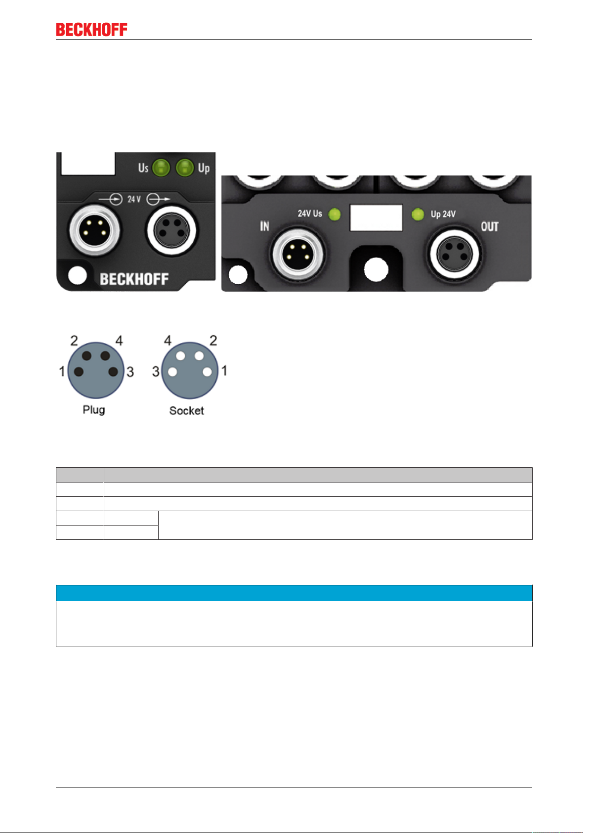
3.2.3 Power Connection
The feeding and forwarding of supply voltages is done via two M8 connectors at the bottom end of the
modules:
• IN: left M8 connector for feeding the supply voltages
• OUT: right M8 connector for forwarding the supply voltages
Fig.17: EtherCAT Box, Connectors for power supply
Fig.18: Pin assignment M8, Power In and Power Out
Table1: PIN assignment
Pin Voltage
1 Control voltage Us, +24V
2 Auxiliary voltage Up, +24V
DC
DC
3 GNDs* *) may be connected internally to each other depending on the module: see specific
4 GNDp*
module descriptions
The pins M8 connectors carry a maximum current of 4A.
Two LEDs display the status of the supply voltages.
NOTE
Don't confuse the power connectors with the EtherCAT connectors!
Never connect the power cables (M8, 24VDC) with the green marked EtherCAT sockets of the EtherCAT
Box Modules! This can damage the modules!
Control voltage Us: 24V
Power is supplied to the fieldbus, the processor logic, the inputs and the sensors from the 24VDC control
voltage Us. The control voltage is electrically isolated from the fieldbus circuitry.
DC
Auxiliary voltage Up 24V
DC
The Auxiliary voltage Up supplies the digital outputs; it can be brought in separately. If the load voltage is
switched off, the fieldbus functions and the power supply and functionality of the inputs are retained.
EP4174-0002 21Version: 1.1.0
Page 22

Mounting and connection
Redirection of the supply voltages
The IN and OUT power connections are bridged in the module (not IP204x-Bxxx and IE204x). The supply
voltages Us and Up can thus easily be transferred from EtherCATBox to EtherCATBox.
NOTE
Pay attention to the maximum permissible current!
Pay attention also for the redirection of the supply voltages Us and Up, the maximum permissible current
for M8 connectors of 4A must not be exceeded!
EP4174-000222 Version: 1.1.0
Page 23

Mounting and connection
Supply via EP92x4-0023 PowerBox modules
If the machine requires higher current or if the EtherCAT Box Modules are installed far away from the control
cabinet with included power supply, the usage of four cannel power distribution modules EP9214 or EP9224
(with integrated data logging, see www.beckhoff.com/EP9224) is recommended.
With these modules intelligent power distribution concepts with up to 2x16A and a maximum of 2.5mm²
cable cross-section can be realized.
Fig.19: EP92x4-0023, Connectors for Power In and Power Out
Fig.20: Pin assignment 7/8”, Power In and Power Out
EP4174-0002 23Version: 1.1.0
Page 24

Mounting and connection
Electrical isolation
Digital modules
In the digital input/output modules, the grounds of the control voltage (GNDs) and the auxiliary voltage
(GNDp) are connected to each other!
Check this at the documentation of each used EtherCAT Box.
Analog modules
In the analog input/output modules the grounds of the control voltage (GNDs) and the auxiliary voltage
(GNDp) are separated from each other in order to ensure electrical isolation of the analog signals from the
control voltage.
In some of the analog modules the sensors or actuators are supplied by Up - this means, for instance, that in
the case of 0...10 V inputs, any reference voltage (0...30 V) may be connected to Up; this is then available to
the sensors (e.g. smoothed 10 V for measuring potentiometers).
Details of the power supply may be taken from the specific module descriptions.
NOTE
Electrical isolation may be cancelled!
If digital and analog fieldbus boxes are connected directly via four-core power leads, the analog signals in
the fieldbus boxes may be no longer electrically isolated from the control voltage!
3.2.4 Power cables
Ordering data
Order designation Power cable Screw-in connector Contacts Cross-section Length
ZK2020-3200-0020 Straight socket, open end M8 4-pin 0.34 mm
ZK2020-3200-0050 5.00 m
ZK2020-3200-0100 10.00 m
ZK2020-3400-0020 Angled socket, open end 2.00 m
ZK2020-3400-0050 5.00 m
ZK2020-3400-0100 10.00 m
ZK2020-3132-0001 Straight socket, straight
ZK2020-3132-0005 0.50 m
ZK2020-3132-0010 1.00 m
ZK2020-3132-0020 2.00 m
ZK2020-3132-0050 5.00 m
ZK2020-3334-0001 Angled socket, angled
ZK2020-3334-0005 0.50 m
ZK2020-3334-0010 1.00 m
ZK2020-3334-0020 2.00 m
ZK2020-3334-0050 5.00 m
socket
socket
2
2.00 m
0.15 m
0.15 m
Further available power cables may be found in the Beckhoff catalog or on our internet pages (http://
www.beckhoff.com).
EP4174-000224 Version: 1.1.0
Page 25

Mounting and connection
Technical data
Technical data
Rated voltage according to IEC61076-2-101 30V
DC
Contamination level according to IEC 60 664-1 3/2
Insulation resistance IEC 60 512-2 >109Ω
Current carrying capacity according to IEC 60512-3 4A
Volume resistance according to IEC 60512-2 <5mΩ
Protection class according to IEC 60529 IP65/66/67, when screwed together
Ambient temperature -30°C to +80°C
EP4174-0002 25Version: 1.1.0
Page 26

Mounting and connection
3.2.5 Power cable conductor losses M8
The ZK2020-xxxx-yyyy power cables should not exceed the total length of 15m at 4A (with continuation).
When planning the cabling, note that at 24V nominal voltage, the functionality of the module can no longer
be assured if the voltage drop reaches 6V. Variations in the output voltage from the power supply unit must
also be taken into account.
Fig.21: Power cable conductor losses
Example
8m power cable with 0.34mm² cross-section has a voltage drop of 3.2V at 4A.
EP92x4 Power Distribution Modules
With EP9214 and EP9224 Power Distribution Modules intelligent concepts for voltage supply are
available. Further information may be found under www.beckhoff.com/EP9224.
EP4174-000226 Version: 1.1.0
Page 27
Mounting and connection
3.2.6 EP4174-0002 - Signal connection
3.2.6.1 Analog voltage outputs (M12)
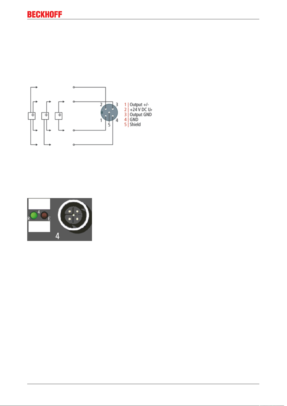
Analog outputs, -10 to +10 V
The actuator is connected via output+/- and outputGND. The actuator can optionally be operated/supplied
with 24VDC.
Fig.22: Connecting the analog voltage outputs (M12)
LED indicators - meanings
There is a green Run LED and a red Error LED for each channel. The green Run LED is lit when data are
transferred to the D/A converter. The red Error LED indicates that there is an error (open circuit, measured
value outside the range).
Correct function is indicated if the green Run LED is on and the red Error is off.
Fig.23: Status and diagnostic LED at the M12 connector
EP4174-0002 27Version: 1.1.0
Page 28

Mounting and connection
3.2.6.2 Analog current outputs (M12)
Analog outputs, 0 to 20mA or 4 to 20mA
The actuator is connected via output+ and output-. The actuator can optionally be operated/supplied with
24VDC.
Fig.24: Connecting the analog current outputs (M12)
LED indicators - meanings
There is a green Run LED and a red Error LED for each channel. The green Run LED is lit when data are
transferred to the D/A converter. The red Error LED indicates that there is an error (open circuit, measured
value outside the range).
Correct function is indicated if the green Run LED is on and the red Error is off.
Fig.25: Status and diagnostic LED at the M12 connector
3.3 UL Requirements
The installation of the EtherCAT Box Modules certified by UL has to meet the following requirements.
Supply voltage
CAUTION
CAUTION!
This UL requirements are valid for all supply voltages of all marked EtherCAT Box Modules!
For the compliance of the UL requirements the EtherCAT Box Modules should only be supplied
• by a 24 VDC supply voltage, supplied by an isolating source and protected by means of a fuse (in accordance with UL248), rated maximum 4 Amp, or
• by a 24 VDC power source, that has to satisfy NEC class 2.
A NEC class 2 power supply shall not be connected in series or parallel with another (class 2) power
source!
CAUTION
CAUTION!
To meet the UL requirements, the EtherCAT Box Modules must not be connected to unlimited power
sources!
EP4174-000228 Version: 1.1.0
Page 29

Mounting and connection
Networks
CAUTION
CAUTION!
To meet the UL requirements, EtherCAT Box Modules must not be connected to telecommunication networks!
Ambient temperature range
CAUTION
CAUTION!
To meet the UL requirements, EtherCAT Box Modules has to be operated only at an ambient temperature
range of 0 to 55°C!
Marking for UL
All EtherCAT Box Modules certified by UL (Underwriters Laboratories) are marked with the following label.
Fig.26: UL label
EP4174-0002 29Version: 1.1.0
Page 30

Mounting and connection
3.4 ATEX notes
3.4.1 ATEX - Special conditions
WARNING
Observe the special conditions for the intended use of EtherCAT Box modules in potentially explosive areas – directive 94/9/EU.
• The certified components are to be installed in the BG2000-0000 protection enclosure [}31] that guarantees a protection against mechanical hazards!
• If the temperatures during rated operation are higher than 70°C at the feed-in points of cables, lines or
pipes, or higher than 80°C at the wire branching points, then cables must be selected whose temperature data correspond to the actual measured temperature values!
• Observethe permissible ambient temperature range of 0 - 55°C for the use of EtherCAT Box modules in
potentially explosive areas!
• Measures must be taken to protect against the rated operating voltage being exceeded by more than
40% due to short-term interference voltages!
• The connections of the certified components may only be connected or disconnected if the supply voltage has been switched off or if a non-explosive atmosphere is ensured!
Standards
The fundamental health and safety requirements are fulfilled by compliance with the following standards:
• EN 60079-0: 2006
• EN 60079-15: 2005
Marking
The EtherCAT Box modules certified for potentially explosive areas bear the following marking:
II 3 GEx nA II T4DEKRA 11ATEX0080 XTa: 0 - 55°C
or
II 3 GEx nA nC IIC T4DEKRA 11ATEX0080 XTa: 0 - 55°C
Batch number (D number)
The EtherCAT Box modules bear a batch number (D number) that is structured as follows:
D: WW YY FF HH
WW - week of production (calendar week)
YY - year of production
FF - firmware version
HH - hardware version
Beispiel mit Ser. Nr.: 29 10 02 01:
29 - week of production 29
10 - year of production 2010
02 - firmware version 02
01 - hardware version 01
EP4174-000230 Version: 1.1.0
Page 31

Mounting and connection
3.4.2 BG2000-0000 - EtherCAT Box protection enclosure
WARNING
Risk of electric shock and damage of device!
Bring the EtherCAT system into a safe, powered down state before starting installation, disassembly or
wiring of the modules!
ATEX
The BG2000-0000 protection enclosure has to be mounted over a single EtherCAT Box to fulfill the special
conditions according to ATEX [}30].
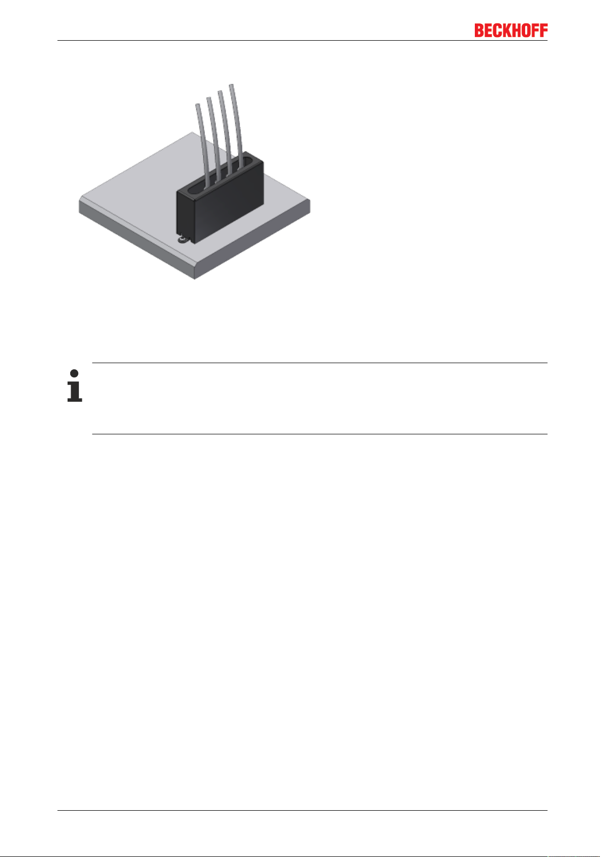
Installation
Put the cables for EtherCAT, power supply and sensors/actuators through the hole of the BG2000-0000
protection enclosure.
Fig.27: BG2000-0000, putting the cables
Fix the wires for EtherCAT, power supply and sensors/actuators to the EtherCAT Box.
Fig.28: BG2000-0000, fixing the cables
EP4174-0002 31Version: 1.1.0
Page 32
Mounting and connection
Mount the BG2000-0000 protection enclosure over the EtherCAT Box.
Fig.29: BG2000-0000, mounting the protection enclosure
3.4.3 ATEX Documentation
Notes about operation of EtherCAT Box Modules (EPxxxx-xxxx) in potentially explosive areas (ATEX)
Pay also attention to the continuative documentationNotes about operation of EtherCAT Box Modules (EPxxxx-xxxx) in potentially explosive areas (ATEX) that is available in the download area of
the Beckhoff homepage http:\\www.beckhoff.com!
EP4174-000232 Version: 1.1.0
Page 33
Commissioning/Configuration
4 Commissioning/Configuration
4.1 Inserting into the EtherCAT network
Installation of the latest XML device description
Please ensure that you have installed the latest XML device description in TwinCAT. This can be
downloaded from the Beckhoff website (http://www.beckhoff.de/english/download/elconfg.htm?
id=1983920606140) and installed according to the installation instructions.
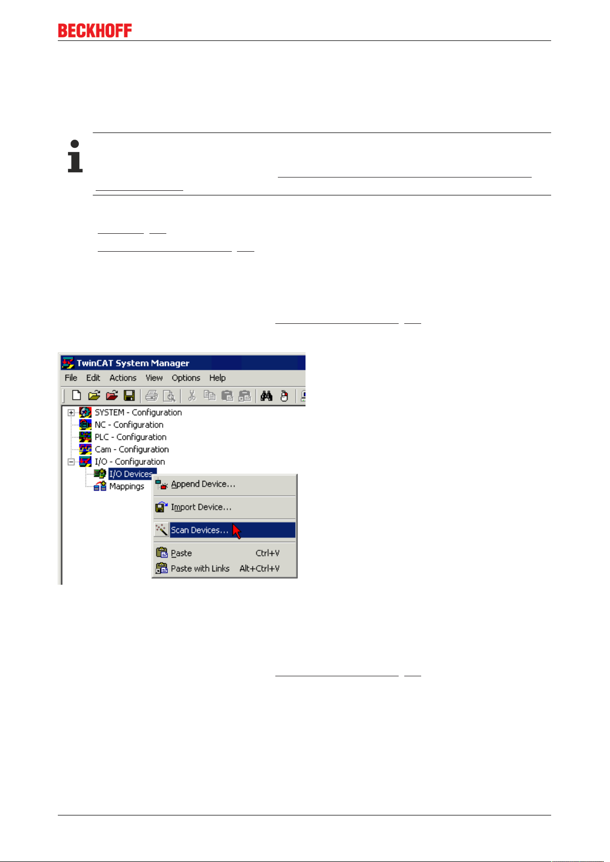
At the Beckhoff TwinCAT System Manager the configuration tree can be build in two different ways:
• by scanning [}33] for existing hardware (called "online") and
• by manual inserting/appending [}33] of fieldbus devices, couplers and slaves.
Automatic scanning in of the box
• The EtherCAT system must be in a safe, de-energized state before the EtherCAT modules are
connected to the EtherCAT network!
• Switch on the operating voltage, open the TwinCAT System Manager [}36] (Config mode), and scan
in the devices (see Fig. 1). Acknowledge all dialogs with "OK", so that the configuration is in "FreeRun"
mode.
Fig.30: Scanning in the configuration (I/O Devices -> right-click -> Scan Devices...)
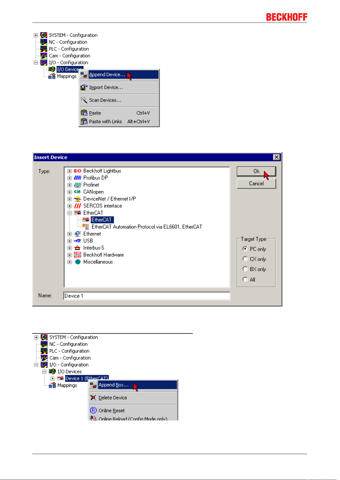
Appending a module manually
• The EtherCAT system must be in a safe, de-energized state before the EtherCAT modules are
connected to the EtherCAT network!
• Switch on the operating voltage, open the TwinCAT System Manager [}36] (Config mode)
• Append a new I/O device. In the dialog that appears select the device EtherCAT (Direct Mode), and
confirm with OK.
EP4174-0002 33Version: 1.1.0
Page 34
Commissioning/Configuration
Fig.31: Appending a new I/O device (I/O Devices -> right-click -> Append Device...)
Fig.32: Selecting the device EtherCAT
• Append a new box.
Fig.33: Appending a new box (Device -> right-click -> Append Box...)
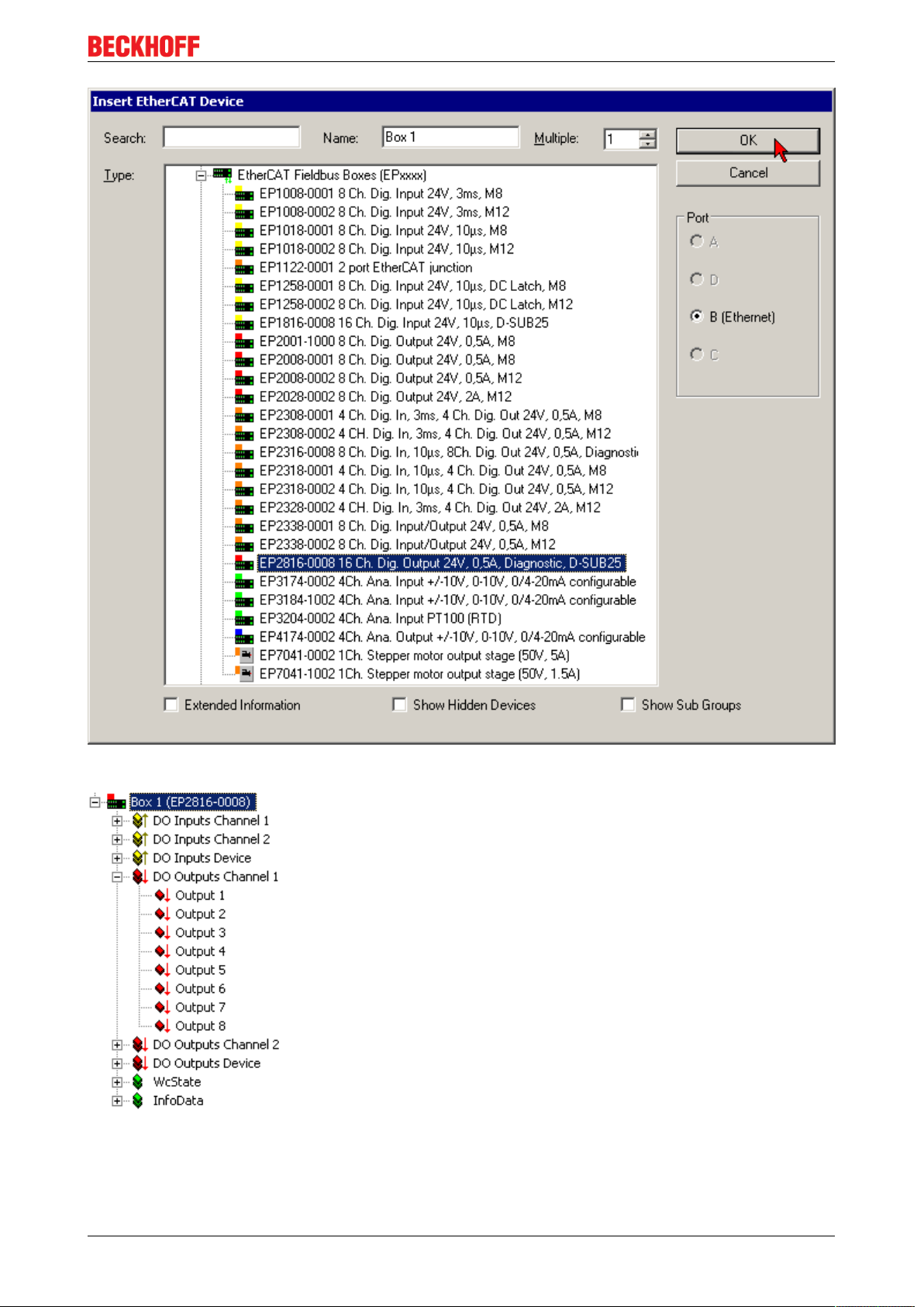
• In the dialog that appears select the desired box (e.g. EP2816-0008), and confirm with OK.
EP4174-000234 Version: 1.1.0
Page 35
Commissioning/Configuration
Fig.34: Selecting a Box (e.g. EP2816-0008)
Fig.35: Appended Box in the TwinCAT tree
EP4174-0002 35Version: 1.1.0
Page 36

Commissioning/Configuration
4.2 Configuration via TwinCAT
In the left-hand window of the TwinCAT System Manager, click on the branch of the EtherCAT Box you wish
to configure (EP2816-0008 in this example).
Fig.36: Branch of the EtherCAT box to be configured
In the right-hand window of the TwinCAT System manager, various tabs are now available for configuring
the EtherCAT Box.
General tab
Fig.37: General tab
Name Name of the EtherCAT device
Id Number of the EtherCAT device
Type EtherCAT device type
Comment Here you can add a comment (e.g. regarding the system).
Disabled Here you can deactivate the EtherCAT device.
Create symbols Access to this EtherCAT slave via ADS is only available if this checkbox is
activated.
EP4174-000236 Version: 1.1.0
Page 37

Commissioning/Configuration
EtherCAT tab
Fig.38: EtherCAT tab
Type EtherCAT device type
Product/Revision Product and revision number of the EtherCAT device
Auto Inc Addr. Auto increment address of the EtherCAT device. The auto increment address can
be used for addressing each EtherCAT device in the communication ring through
its physical position. Auto increment addressing is used during the start-up phase
when the EtherCAT master allocates addresses to the EtherCAT devices. With
auto increment addressing the first EtherCAT slave in the ring has the address
0000
. For each further slave the address is decremented by 1 (FFFF
hex
, FFFE
hex
etc.).
EtherCAT Addr. Fixed address of an EtherCAT slave. This address is allocated by the EtherCAT
master during the start-up phase. Tick the checkbox to the left of the input field in
order to modify the default value.
Previous Port Name and port of the EtherCAT device to which this device is connected. If it is
possible to connect this device with another one without changing the order of the
EtherCAT devices in the communication ring, then this combobox is activated and
the EtherCAT device to which this device is to be connected can be selected.
Advanced Settings This button opens the dialogs for advanced settings.
hex
The link at the bottom of the tab points to the product page for this EtherCAT device on the web.
Process Data tab
Indicates the configuration of the process data. The input and output data of the EtherCAT slave are
represented as CANopen process data objects (PDO). The user can select a PDO via PDO assignment and
modify the content of the individual PDO via this dialog, if the EtherCAT slave supports this function.
EP4174-0002 37Version: 1.1.0
Page 38

Commissioning/Configuration
Fig.39: Process Data tab
Sync Manager
Lists the configuration of the Sync Manager (SM).
If the EtherCAT device has a mailbox, SM0 is used for the mailbox output (MbxOut) and SM1 for the mailbox
input (MbxIn).
SM2 is used for the output process data (outputs) and SM3 (inputs) for the input process data.
If an input is selected, the corresponding PDO assignment is displayed in the PDO Assignment list below.
PDO Assignment
PDO assignment of the selected Sync Manager. All PDOs defined for this Sync Manager type are listed
here:
• If the output Sync Manager (outputs) is selected in the Sync Manager list, all RxPDOs are displayed.
• If the input Sync Manager (inputs) is selected in the Sync Manager list, all TxPDOs are displayed.
The selected entries are the PDOs involved in the process data transfer. In the tree diagram of the System
Manager these PDOs are displayed as variables of the EtherCAT device. The name of the variable is
identical to the Name parameter of the PDO, as displayed in the PDO list. If an entry in the PDO assignment
list is deactivated (not selected and greyed out), this indicates that the input is excluded from the PDO
assignment. In order to be able do select a greyed out PDO, the currently selected PDO has to be
deselected first.
EP4174-000238 Version: 1.1.0
Page 39

Commissioning/Configuration
Activation of PDO assignment
• the EtherCAT slave has to run through the PS status transition cycle (from pre-operational to
safe-operational) once (see Online tab [}42]),
• and the System Manager has to reload the EtherCAT slaves ( button)
PDO list
List of all PDOs supported by this EtherCAT device. The content of the selected PDOs is displayed in the
PDO Content list. The PDO configuration can be modified by double-clicking on an entry.
Column Description
Index PDO index.
Size Size of the PDO in bytes.
Name Name of the PDO.
If this PDO is assigned to a Sync Manager, it appears as a variable of the slave with this
parameter as the name.
Flags F Fixed content: The content of this PDO is fixed and cannot be changed by the System
Manager.
M Mandatory PDO. This PDO is mandatory and must therefore be assigned to a Sync Manager!
Consequently, this PDO cannot be deleted from the PDO Assignment list
SM Sync Manager to which this PDO is assigned. If this entry is empty, this PDO does not take part in
the process data traffic.
SU Sync unit to which this PDO is assigned.
PDO Content
Indicates the content of the PDO. If flag F (fixed content) of the PDO is not set the content can be modified.
Download
If the device is intelligent and has a mailbox, the configuration of the PDO and the PDO assignments can be
downloaded to the device. This is an optional feature that is not supported by all EtherCAT slaves.
PDO Assignment
If this check box is selected, the PDO assignment that is configured in the PDO Assignment list is
downloaded to the device on startup. The required commands to be sent to the device can be viewed in the
Startup [}39] tab.
PDO Configuration
If this check box is selected, the configuration of the respective PDOs (as shown in the PDO list and the
PDO Content display) is downloaded to the EtherCAT slave.
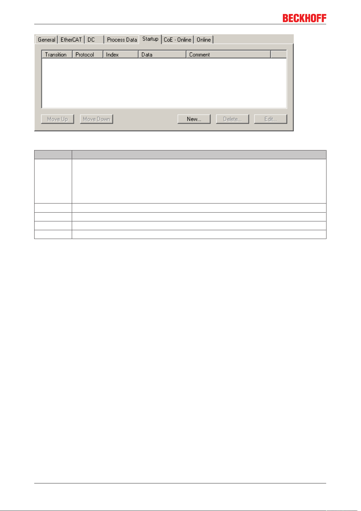
Startup tab
The Startup tab is displayed if the EtherCAT slave has a mailbox and supports the CANopen over EtherCAT
(CoE) or Servo drive over EtherCAT protocol. This tab indicates which download requests are sent to the
mailbox during startup. It is also possible to add new mailbox requests to the list display. The download
requests are sent to the slave in the same order as they are shown in the list.
EP4174-0002 39Version: 1.1.0
Page 40
Commissioning/Configuration
Fig.40: Startup tab
Column Description
Transition Transition to which the request is sent. This can either be
• the transition from pre-operational to safe-operational (PS), or
• the transition from safe-operational to operational (SO).
If the transition is enclosed in "<>" (e.g. <PS>), the mailbox request is fixed and cannot be
modified or deleted by the user.
Protocol Type of mailbox protocol
Index Index of the object
Data Date on which this object is to be downloaded.
Comment Description of the request to be sent to the mailbox
Move Up This button moves the selected request up by one position in the list.
Move Down This button moves the selected request down by one position in the list.
New This button adds a new mailbox download request to be sent during startup.
Delete This button deletes the selected entry.
Edit This button edits an existing request.
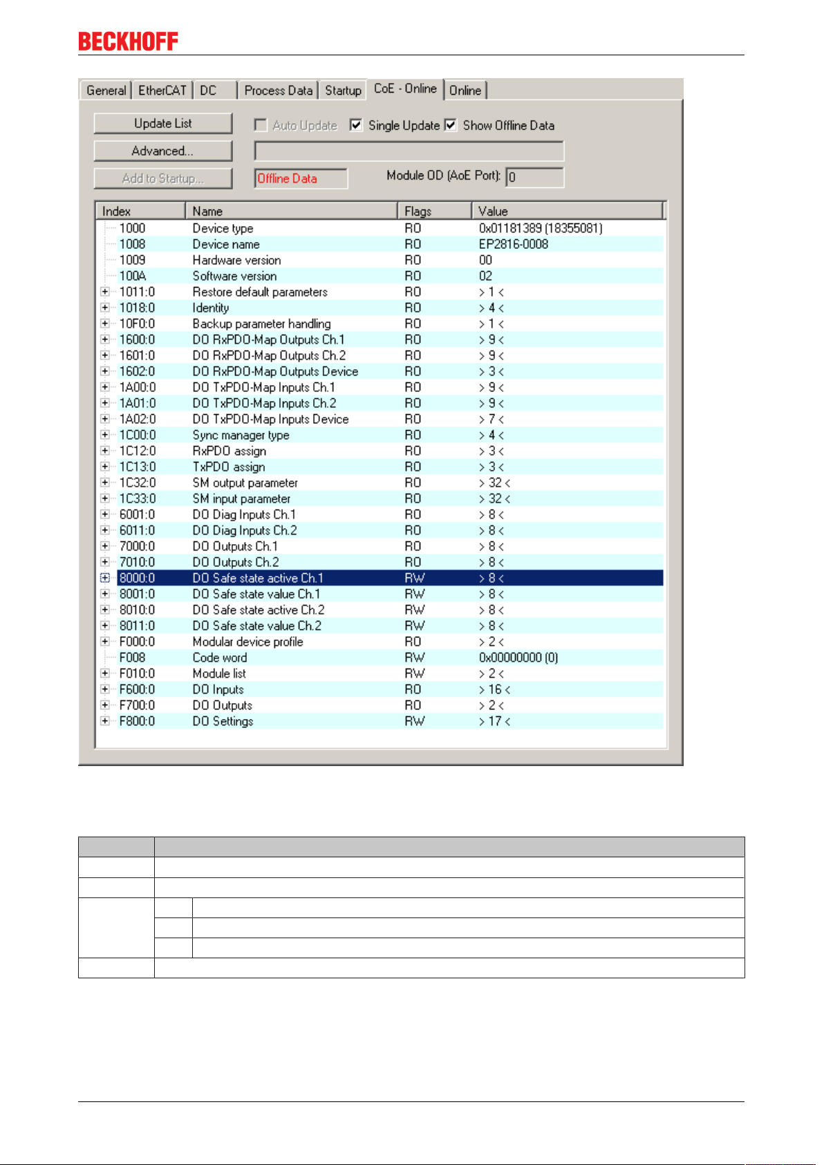
CoE - Online tab
The additional CoE - Online tab is displayed if the EtherCAT slave supports the CANopen over EtherCAT
(CoE) protocol. This dialog lists the content of the object directory of the slave (SDO upload) and enables the
user to modify the content of an object from this list. Details for the objects of the individual EtherCAT
devices can be found in the device-specific object descriptions.
EP4174-000240 Version: 1.1.0
Page 41
Commissioning/Configuration
Fig.41: CoE - Online tab
Object list display
Column Description
Index Index and subindex of the object
Name Name of the object
Flags RW The object can be read, and data can be written to the object (read/write)
RO The object can be read, but no data can be written to the object (read only)
P An additional P identifies the object as a process data object.
Value Value of the object
Update List The Update list button updates all objects in the displayed list
Auto Update If this check box is selected, the content of the objects is updated automatically.
Advanced The Advanced button opens the Advanced Settings dialog. Here you can specify which
objects are displayed in the list.
EP4174-0002 41Version: 1.1.0
Page 42

Commissioning/Configuration
Fig.42: Advanced settings
Online
- via SDO information
Offline
- via EDS file
Online tab
If this option button is selected, the list of the objects included in the object
directory of the slave is uploaded from the slave via SDO information. The list
below can be used to specify which object types are to be uploaded.
If this option button is selected, the list of the objects included in the object
directory is read from an EDS file provided by the user.
Fig.43: Online tab
EP4174-000242 Version: 1.1.0
Page 43

Commissioning/Configuration
State Machine
Init This button attempts to set the EtherCAT device to the Init state.
Pre-Op This button attempts to set the EtherCAT device to the pre-operational state.
Op This button attempts to set the EtherCAT device to the operational state.
Bootstrap This button attempts to set the EtherCAT device to the Bootstrap state.
Safe-Op This button attempts to set the EtherCAT device to the safe-operational state.
Clear Error This button attempts to delete the fault display. If an EtherCAT slave fails during
change of state it sets an error flag.
Example: An EtherCAT slave is in PREOP state (pre-operational). The master now
requests the SAFEOP state (safe-operational). If the slave fails during change of
state it sets the error flag. The current state is now displayed as ERR PREOP. When
the Clear Error button is pressed the error flag is cleared, and the current state is
displayed as PREOP again.
Current State Indicates the current state of the EtherCAT device.
Requested State Indicates the state requested for the EtherCAT device.
DLL Status
Indicates the DLL status (data link layer status) of the individual ports of the EtherCAT slave. The DLL status
can have four different states:
Status Description
No Carrier / Open No carrier signal is available at the port, but the port is open.
No Carrier / Closed No carrier signal is available at the port, and the port is closed.
Carrier / Open A carrier signal is available at the port, and the port is open.
Carrier / Closed A carrier signal is available at the port, but the port is closed.
File Access over EtherCAT
Download With this button a file can be written to the EtherCAT device.
Upload With this button a file can be read from the EtherCAT device.
EP4174-0002 43Version: 1.1.0
Page 44

Commissioning/Configuration
4.3 Object overview
EtherCAT XML Device Description
The display matches that of the CoE objects from the EtherCAT XML Device Description. We recommend downloading the latest XML file from the download area of the Beckhoff website and installing it according to installation instructions.
Index (hex) Name Flags Default value
1000 [}52]
1008 [}52]
1009 [}52]
100A [}52]
1011:0
[}47]
1018:0
[}52]
10F0:0
[}52]
1600:0
[}52]
1601:0
[}53]
1602:0
[}53]
1603:0
[}53]
1C00:0
[}53]
1C12:0
[}53]
1C13:0
[}53]
1C32:0
[}54]
Subindex Restore default parameters RO 0x01 (1
1011:01 SubIndex 001 RW 0x00000000 (0
Subindex Identity RO 0x04 (4
1018:01 Vendor ID RO 0x00000002 (2
1018:02 Product code RO 0x104E4052 (273563730
1018:03 Revision RO 0x00100002 (1048578
1018:04 Serial number RO 0x00000000 (0
Subindex Backup parameter handling RO 0x01 (1
10F0:01 Checksum RO 0x00000000 (0
Subindex AO RxPDO-Map Ch.1 RO 0x01 (1
1600:01 SubIndex 001 RO 0x7000:11, 16
Subindex AO RxPDO-Map Ch.2 RO 0x01 (1
1601:01 SubIndex 001 RO 0x7010:11, 16
Subindex AO RxPDO-Map Ch.3 RO 0x01 (1
1602:01 SubIndex 001 RO 0x7020:11, 16
Subindex AO RxPDO-Map Ch.4 RO 0x01 (1
1603:01 SubIndex 001 RO 0x7030:11, 16
Subindex Sync manager type RO 0x04 (4
1C00:01 SubIndex 001 RO 0x01 (1
1C00:02 SubIndex 002 RO 0x02 (2
1C00:03 SubIndex 003 RO 0x03 (3
1C00:04 SubIndex 004 RO 0x04 (4
Subindex RxPDO assign RW 0x04 (4
1C12:01 SubIndex 001 RW 0x1600 (5632
1C12:02 SubIndex 002 RW 0x1601 (5633
1C12:03 SubIndex 003 RW 0x1602 (5634
1C12:04 SubIndex 004 RW 0x1603 (5635
Subindex TxPDO assign RW 0x00 (0
Subindex SM output parameter RO 0x20 (32
1C32:01 Sync mode RW 0x0001 (1
1C32:02 Cycle time RW 0x000F4240 (1000000
1C32:03 Shift time RO 0x00003A98 (15000
1C32:04 Sync modes supported RO 0xC007 (49159
1C32:05 Minimum cycle time RO 0x000493E0 (300000
1C32:06 Calc and copy time RO 0x00000000 (0
1C32:07 Minimum delay time RO 0x00003A98 (15000
1C32:08 Command RW 0x0000 (0
1C32:09 Maximum Delay time RO 0x00003A98 (15000
1C32:0B SM event missed counter RO 0x0000 (0
1C32:0C Cycle exceeded counter RO 0x0000 (0
1C32:0D Shift too short counter RO 0x0000 (0
1C32:20 Sync error RO 0x00 (0
Device type RO 0x01901389 (26219401
Device name RO EP4174-0002
Hardware version RO 00
Software version RO 01
)
dec
)
dec
)
dec
)
dec
)
dec
)
dec
)
dec
)
dec
)
dec
)
dec
)
dec
)
dec
)
dec
)
dec
)
dec
dec
dec
dec
dec
dec
)
dec
)
dec
)
dec
)
dec
)
dec
)
dec
)
dec
)
dec
)
dec
)
dec
)
dec
)
dec
)
)
dec
)
dec
)
dec
)
dec
)
dec
)
dec
)
)
dec
)
)
)
EP4174-000244 Version: 1.1.0
Page 45

Commissioning/Configuration
Index (hex) Name Flags Default value
7000:0
[}55]
7010:0
[}55]
7020:0
[}55]
7030:0
[}55]
8000:0
[}48]
800E:0
[}55]
800F:0
[}55]
8010:0
[}49]
801E:0
[}55]
801F:0
[}56]
Subindex AO outputs Ch.1 RO 0x11 (17
7000:11 Analog output RO 0x0000 (0
Subindex AO outputs Ch.2 RO 0x11 (17
7010:11 Analog output RO 0x0000 (0
Subindex AO outputs Ch.3 RO 0x11 (17
7020:11 Analog output RO 0x0000 (0
Subindex AO outputs Ch.4 RO 0x11 (17
7030:11 Analog output RO 0x0000 (0
Subindex AO settings Ch.1 RW 0x16 (22
8000:01 Enable user scale RW 0x00 (0
8000:02 Presentation RW 0x00 (0
8000:05 Watchdog RW 0x00 (0
8000:07 Enable user calibration RW 0x00 (0
8000:08 Enable vendor calibration RW 0x01 (1
8000:11 User scale offset RW 0x0000 (0
8000:12 User scale gain RW 0x00010000 (65536
8000:13 Default output RW 0x0000 (0
8000:14 Default output ramp RW 0xFFFF (65535
8000:15 User calibration offset RW 0x0000 (0
8000:16 User calibration gain RW 0x4000 (16384
Subindex AO internal data Ch.1 RO 0x01 (1
800E:01 DAC raw value RO 0x0000 (0
Subindex AO vendor data Ch.1 RW 0x06 (6
800F:01 R0 Calibration Offset RW 0x0000 (0
800F:02 R0 Calibration Gain RW 0x4000 (16384
800F:03 R1 Calibration Offset RW 0x0000 (0
800F:04 R1 Calibration Gain RW 0x4000 (16384
800F:05 R2 Calibration Offset RW 0x0000 (0
800F:06 R2 Calibration Gain RW 0x4000 (16384
Subindex AO settings Ch.2 RW 0x16 (22
8010:01 Enable user scale RW 0x00 (0
8010:02 Presentation RW 0x00 (0
8010:05 Watchdog RW 0x00 (0
8010:07 Enable user calibration RW 0x00 (0
8010:08 Enable vendor calibration RW 0x01 (1
8010:11 User scale offset RW 0x0000 (0
8010:12 User scale gain RW 0x00010000 (65536
8010:13 Default output RW 0x0000 (0
8010:14 Default output ramp RW 0xFFFF (65535
8010:15 User calibration offset RW 0x0000 (0
8010:16 User calibration gain RW 0x4000 (16384
Subindex AO internal data Ch.2 RO 0x01 (1
801E:01 DAC raw value RO 0x0000 (0
Subindex AO vendor data Ch.2 RW 0x06 (6
801F:01 R0 Calibration Offset RW 0x0000 (0
801F:02 R0 Calibration Gain RW 0x4000 (16384
801F:03 R1 Calibration Offset RW 0x0000 (0
801F:04 R1 Calibration Gain RW 0x4000 (16384
801F:05 R2 Calibration Offset RW 0x0000 (0
801F:06 R2 Calibration Gain RW 0x4000 (16384
)
dec
dec
)
dec
dec
)
dec
dec
)
dec
dec
)
dec
)
dec
)
dec
)
dec
)
dec
)
dec
dec
dec
dec
)
dec
dec
)
dec
dec
dec
dec
)
dec
)
dec
)
dec
)
dec
)
dec
)
dec
dec
dec
dec
)
dec
dec
)
dec
dec
dec
dec
)
)
)
)
)
)
dec
)
)
dec
)
)
dec
)
)
)
dec
)
)
dec
)
)
dec
)
)
dec
)
)
dec
)
)
dec
)
)
)
dec
)
)
dec
)
)
dec
EP4174-0002 45Version: 1.1.0
Page 46

Commissioning/Configuration
Index (hex) Name Flags Default value
8020:0
[}50]
802E:0
[}56]
802F:0
[}56]
8030:0
[}51]
803E:0
[}56]
803F:0
[}56]
F000:0
[}56]
F008 [}57]
F010:0
[}57]
F800:0
[}51]
Subindex AO settings Ch.3 RW 0x16 (22
8020:01 Enable user scale RW 0x00 (0
8020:02 Presentation RW 0x00 (0
8020:05 Watchdog RW 0x00 (0
8020:07 Enable user calibration RW 0x00 (0
8020:08 Enable vendor calibration RW 0x01 (1
8020:11 User scale offset RW 0x0000 (0
8020:12 User scale gain RW 0x00010000 (65536
8020:13 Default output RW 0x0000 (0
8020:14 Default output ramp RW 0xFFFF (65535
8020:15 User calibration offset RW 0x0000 (0
8020:16 User calibration gain RW 0x4000 (16384
Subindex AO internal data Ch.3 RO 0x01 (1
802E:01 DAC raw value RO 0x0000 (0
Subindex AO vendor data Ch.3 RW 0x06 (6
802F:01 R0 Calibration Offset RW 0x0000 (0
802F:02 R0 Calibration Gain RW 0x4000 (16384
802F:03 R1 Calibration Offset RW 0x0000 (0
802F:04 R1 Calibration Gain RW 0x4000 (16384
802F:05 R2 Calibration Offset RW 0x0000 (0
802F:06 R2 Calibration Gain RW 0x4000 (16384
Subindex AO settings Ch.4 RW 0x16 (22
8030:01 Enable user scale RW 0x00 (0
8030:02 Presentation RW 0x00 (0
8030:05 Watchdog RW 0x00 (0
8030:07 Enable user calibration RW 0x00 (0
8030:08 Enable vendor calibration RW 0x01 (1
8030:11 User scale offset RW 0x0000 (0
8030:12 User scale gain RW 0x00010000 (65536
8030:13 Default output RW 0x0000 (0
8030:14 Default output ramp RW 0xFFFF (65535
8030:15 User calibration offset RW 0x0000 (0
8030:16 User calibration gain RW 0x4000 (16384
Subindex AO internal data Ch.4 RO 0x01 (1
803E:01 DAC raw value RO 0x0000 (0
Subindex AO vendor data Ch.4 RW 0x06 (6
803F:01 R0 Calibration Offset RW 0x0000 (0
803F:02 R0 Calibration Gain RW 0x4000 (16384
803F:03 R1 Calibration Offset RW 0x0000 (0
803F:04 R1 Calibration Gain RW 0x4000 (16384
803F:05 R2 Calibration Offset RW 0x0000 (0
803F:06 R2 Calibration Gain RW 0x4000 (16384
Subindex Modular device profile RO 0x02 (2
F000:01 Module index distance RO 0x0010 (16
F000:02 Maximum number of modules RO 0x0004 (4
Code word RW 0x00000000 (0
Subindex Module list RW 0x04 (4
F010:01 SubIndex 001 RW 0x00000190 (400
F010:02 SubIndex 002 RW 0x00000190 (400
F010:03 SubIndex 003 RW 0x00000190 (400
F010:04 SubIndex 004 RW 0x00000190 (400
Subindex AO Range Settings RW 0x04 (4
F800:01 Output type Ch1 RW 0x0000 (0
F800:02 Output type Ch2 RW 0x0000 (0
F800:03 Output type Ch3 RW 0x0000 (0
F800:04 Output type Ch4 RW 0x0000 (0
)
dec
)
dec
)
dec
)
dec
)
dec
)
dec
dec
dec
dec
)
dec
dec
)
dec
dec
dec
dec
)
dec
)
dec
)
dec
)
dec
)
dec
)
dec
dec
dec
dec
)
dec
dec
)
dec
dec
dec
dec
)
dec
dec
)
dec
)
dec
dec
dec
dec
dec
)
)
dec
)
)
dec
)
)
dec
)
)
)
dec
)
)
dec
)
)
dec
)
)
dec
)
)
dec
)
)
dec
)
)
)
dec
)
)
dec
)
)
dec
)
dec
)
)
dec
)
dec
)
dec
)
dec
)
dec
)
)
)
)
EP4174-000246 Version: 1.1.0
Page 47

Commissioning/Configuration
Legend
Flags:
RO (Read Only): this object can be read only
RW (Read/Write): this object can be read and written to
4.4 Object description and parameterization
EtherCAT XML Device Description
The display matches that of the CoE objects from the EtherCAT XML Device Description. We recommend downloading the latest XML file from the download area of the Beckhoff website and installing it according to installation instructions.
Parameterization via the CoE list (CAN over EtherCAT)
The EtherCAT device is parameterized via the CoE - Online tab [}40] (double-click on the respective object) or via the Process Data [}37] tab (allocation of PDOs).
Introduction
The CoE overview contains objects for different intended applications:
• Objects required for parameterization [}47] during commissioning
• Objects intended for regular operation [}52], e.g. through ADS access.
• Objects for indicating internal settings [}52] (may be fixed)
• Further profile-specific objects [}55] indicating inputs, outputs and status information
The following section first describes the objects required for normal operation, followed by a complete
overview of missing objects.
4.4.1 Objects to be parameterized during commissioning
Index 1011 Restore default parameters
Index (hex) Name Meaning Data type Flags Default
1011:0 Restore default pa-
rameters
1011:01 SubIndex 001 If this object is set to "0x64616F6C" in the set value dia-
Restore default parameters UINT8 RO 0x01 (1
log, all backup objects are reset to their delivery state.
UINT32 RW 0x00000000
(0
)
dec
)
dec
EP4174-0002 47Version: 1.1.0
Page 48

Commissioning/Configuration
Index 8000 AO settings Ch.1
Index (hex) Name Meaning Data type Flags Default
8000:0 AO settings Ch.1 Maximum subindex UINT8 RO 0x16 (22
8000:01 Enable user scale This entry activates the scaling for 0x8pp0:11 and
0x8pp0:12.
8000:02 Presentation 0 Signed presentation
The output value range 0x7pp1:11 is shown as
16bit signed integer. For unipolar terminals
(0-10Vor 0-20mA) the negative range is set to
zero.
1 Unsigned presentation
The output value range 0x7pp1:11 is shown as
16bit unsigned integer. Negative values are not
possible.
2 Absolute value with MSB as sign
Signed amount representation is active.
3 Absolute value
The absolute value of the signed representation is
formed.
8000:05 Watchdog 0 Default watchdog value
The default value (0x8pp0:13) is active.
1 Watchdog ramp
The ramp (0x8pp0:14) for moving to the default
value ((0x8pp0:13)) is active.
2 Last output value
In the event of an error (triggering of the watchdog)
the last process data is output.
8000:07 Enable user calibra-
Enables user calibration BOOLEAN RW 0x00 (0
tion
8000:08 Enable vendor cali-
Enable vendor calibration BOOLEAN RW 0x01 (1
bration
8000:11 User scale offset User scaling: Offset INT16 RW 0x0000 (0
8000:12 User scale gain User scaling: Gain.
The gain is represented in fixed-point format, with the
-16
factor 2
. The value one corresponds to 65535
(0x00010000).
8000:13 Default output Default output value INT16 RW 0x0000 (0
8000:14 Default output ramp This value defines the ramps for the ramp-down to the
default value. The value is specified in digits / ms.
If the entry is 100 and the default value 0, forexample, it
takes 327ms (32767/100) for the output value to change
from the maximum value (32767) to the default value in
the event of a fault.
8000:15 User calibration offset User calibration: Offset INT16 RW 0x0000 (0
8000:16 User calibration gain User calibration: Gain UINT16 RW 0x4000
BOOLEAN RW 0x00 (0
BIT3 RW 0x00 (0
BIT2 RW 0x00 (0
INT32 RW 0x00010000
(65536
UINT16 RW 0xFFFF
(65535
(16384
)
dec
)
dec
)
dec
)
dec
)
dec
)
dec
)
dec
)
dec
)
dec
)
dec
)
dec
)
dec
EP4174-000248 Version: 1.1.0
Page 49

Commissioning/Configuration
Index 8010 AO settings Ch.2
Index (hex) Name Meaning Data type Flags Default
8010:0 AO settings Ch.2 Maximum subindex UINT8 RO 0x16 (22
8010:01 Enable user scale This entry activates the scaling for 0x8pp0:11 and
0x8pp0:12.
8010:02 Presentation 0 Signed presentation
The output value range 0x7pp1:11 is shown as
16bit signed integer. For unipolar terminals
(0-10Vor 0-20mA) the negative range is set to
zero.
1 Unsigned presentation
The output value range 0x7pp1:11 is shown as
16bit unsigned integer. Negative values are not
possible.
2 Absolute value with MSB as sign
Signed amount representation is active.
3 Absolute value
The absolute value of the signed representation is
formed.
8010:05 Watchdog 0 Default watchdog value
The default value (0x8pp0:13) is active.
1 Watchdog ramp
The ramp (0x8pp0:14) for moving to the default
value ((0x8pp0:13)) is active.
2 Last output value
In the event of an error (triggering of the watchdog)
the last process data is output.
8010:07 Enable user calibra-
Enables user calibration BOOLEAN RW 0x00 (0
tion
8010:08 Enable vendor cali-
Enable vendor calibration BOOLEAN RW 0x01 (1
bration
8010:11 User scale offset User scaling: Offset INT16 RW 0x0000 (0
8010:12 User scale gain User scaling: Gain.
The gain is represented in fixed-point format, with the
-16
factor 2
. The value one corresponds to 65535
(0x00010000).
8010:13 Default output Default output value INT16 RW 0x0000 (0
8010:14 Default output ramp This value defines the ramps for the ramp-down to the
default value. The value is specified in digits / ms.
If the entry is 100 and the default value 0, forexample, it
takes 327ms (32767/100) for the output value to change
from the maximum value (32767) to the default value in
the event of a fault.
8010:15 User calibration offset User calibration: Offset INT16 RW 0x0000 (0
8010:16 User calibration gain User calibration: Gain UINT16 RW 0x4000
BOOLEAN RW 0x00 (0
BIT3 RW 0x00 (0
BIT2 RW 0x00 (0
INT32 RW 0x00010000
(65536
UINT16 RW 0xFFFF
(65535
(16384
)
dec
)
dec
)
dec
)
dec
)
dec
)
dec
)
dec
)
dec
)
dec
)
dec
)
dec
)
dec
EP4174-0002 49Version: 1.1.0
Page 50

Commissioning/Configuration
Index 8020 AO settings Ch.3
Index (hex) Name Meaning Data type Flags Default
8020:0 AO settings Ch.3 Maximum subindex UINT8 RO 0x16 (22
8020:01 Enable user scale This entry activates the scaling for 0x8pp0:11 and
0x8pp0:12.
8020:02 Presentation 0 Signed presentation
The output value range 0x7pp1:11 is shown as
16bit signed integer. For unipolar terminals
(0-10Vor 0-20mA) the negative range is set to
zero.
1 Unsigned presentation
The output value range 0x7pp1:11 is shown as
16bit unsigned integer. Negative values are not
possible.
2 Absolute value with MSB as sign
Signed amount representation is active.
3 Absolute value
The absolute value of the signed representation is
formed.
8020:05 Watchdog 0 Default watchdog value
The default value (0x8pp0:13) is active.
1 Watchdog ramp
The ramp (0x8pp0:14) for moving to the default
value ((0x8pp0:13)) is active.
2 Last output value
In the event of an error (triggering of the watchdog)
the last process data is output.
8020:07 Enable user calibra-
Enables user calibration BOOLEAN RW 0x00 (0
tion
8020:08 Enable vendor cali-
Enable vendor calibration BOOLEAN RW 0x01 (1
bration
8020:11 User scale offset User scaling: Offset INT16 RW 0x0000 (0
8020:12 User scale gain User scaling: Gain.
The gain is represented in fixed-point format, with the
-16
factor 2
. The value one corresponds to 65535
(0x00010000).
8020:13 Default output Default output value INT16 RW 0x0000 (0
8020:14 Default output ramp This value defines the ramps for the ramp-down to the
default value. The value is specified in digits / ms.
If the entry is 100 and the default value 0, forexample, it
takes 327ms (32767/100) for the output value to change
from the maximum value (32767) to the default value in
the event of a fault.
8020:15 User calibration offset User calibration: Offset INT16 RW 0x0000 (0
8020:16 User calibration gain User calibration: Gain UINT16 RW 0x4000
BOOLEAN RW 0x00 (0
BIT3 RW 0x00 (0
BIT2 RW 0x00 (0
INT32 RW 0x00010000
(65536
UINT16 RW 0xFFFF
(65535
(16384
)
dec
)
dec
)
dec
)
dec
)
dec
)
dec
)
dec
)
dec
)
dec
)
dec
)
dec
)
dec
EP4174-000250 Version: 1.1.0
Page 51

Commissioning/Configuration
Index 8030 AO settings Ch.4
Index (hex) Name Meaning Data type Flags Default
8030:0 AO settings Ch.4 Maximum subindex UINT8 RO 0x16 (22
8030:01 Enable user scale This entry activates the scaling for 0x8pp0:11 and
0x8pp0:12.
8030:02 Presentation 0 Signed presentation
The output value range 0x7pp1:11 is shown as
16bit signed integer. For unipolar terminals
(0-10Vor 0-20mA) the negative range is set to
zero.
1 Unsigned presentation
The output value range 0x7pp1:11 is shown as
16bit unsigned integer. Negative values are not
possible.
2 Absolute value with MSB as sign
Signed amount representation is active.
3 Absolute value
The absolute value of the signed representation is
formed.
8030:05 Watchdog 0 Default watchdog value
The default value (0x8pp0:13) is active.
1 Watchdog ramp
The ramp (0x8pp0:14) for moving to the default
value ((0x8pp0:13)) is active.
2 Last output value
In the event of an error (triggering of the watchdog)
the last process data is output.
8030:07 Enable user calibra-
Enables user calibration BOOLEAN RW 0x00 (0
tion
8030:08 Enable vendor cali-
Enable vendor calibration BOOLEAN RW 0x01 (1
bration
8030:11 User scale offset User scaling: Offset INT16 RW 0x0000 (0
8030:12 User scale gain User scaling: Gain.
The gain is represented in fixed-point format, with the
-16
factor 2
. The value one corresponds to 65535
(0x00010000).
8030:13 Default output Default output value INT16 RW 0x0000 (0
8030:14 Default output ramp This value defines the ramps for the ramp-down to the
default value. The value is specified in digits / ms.
If the entry is 100 and the default value 0, forexample, it
takes 327ms (32767/100) for the output value to change
from the maximum value (32767) to the default value in
the event of a fault.
8030:15 User calibration offset User calibration: Offset INT16 RW 0x0000 (0
8030:16 User calibration gain User calibration: Gain UINT16 RW 0x4000
BOOLEAN RW 0x00 (0
BIT3 RW 0x00 (0
BIT2 RW 0x00 (0
INT32 RW 0x00010000
(65536
UINT16 RW 0xFFFF
(65535
(16384
)
dec
)
dec
)
dec
)
dec
)
dec
)
dec
)
dec
)
dec
)
dec
)
dec
)
dec
)
dec
Index F800 AO Range Settings
Index (hex) Name Meaning Data type Flags Default
F800:0 AO Range Settings Maximum subindex UINT8 RO 0x04 (4
F800:01 Output type Ch1 Output signal range for channel 1 UINT16 RW 0x0000 (0
0 -10…+10V
1 0...20mA
2 4...20mA
6 0...10V
F800:02 Output type Ch2 Output signal range for channel 2 (values see channel1) UINT16 RW 0x0000 (0
F800:03 Output type Ch3 Output signal range for channel 3 (values see channel1) UINT16 RW 0x0000 (0
F800:04 Output type Ch4 Output signal range for channel 4 (values see channel1) UINT16 RW 0x0000 (0
EP4174-0002 51Version: 1.1.0
)
dec
)
dec
)
dec
)
dec
)
dec
Page 52

Commissioning/Configuration
4.4.2 Objects for regular operation
The EP4174 has no such objects.
4.4.3 Standard objects (0x1000-0x1FFF)
The standard objects have the same meaning for all EtherCAT slaves.
Index 1000 Device type
Index (hex) Name Meaning Data type Flags Default
1000:0 Device type Device type of the EtherCAT slave: The Lo-Word con-
tains the CoE profile used (5001). The Hi-Word contains
the module profile according to the modular device profile.
Index 1008 Device name
Index (hex) Name Meaning Data type Flags Default
1008:0 Device name Device name of the EtherCAT slave STRING RO EP4174-0002
Index 1009 Hardware version
Index (hex) Name Meaning Data type Flags Default
1009:0 Hardware version Hardware version of the EtherCAT slave STRING RO 00
UINT32 RO 0x01901389
(26219401
)
dec
Index 100A Software version
Index (hex) Name Meaning Data type Flags Default
100A:0 Software version Firmware version of the EtherCAT slave STRING RO 01
Index 1018 Identity
Index (hex) Name Meaning Data type Flags Default
1018:0 Identity Information for identifying the slave UINT8 RO 0x04 (4
1018:01 Vendor ID Vendor ID of the EtherCAT slave UINT32 RO 0x00000002
1018:02 Product code Product code of the EtherCAT slave UINT32 RO 0x104E4052
1018:03 Revision Revision numberof the EtherCAT slave; the low word (bit
0-15) indicates the special terminal number, the high
word (bit 16-31) refers to the device description
1018:04 Serial number Serial number of the EtherCAT slave; the low byte (bit
0-7) of the low word contains the year of production, the
high byte (bit 8-15) of the low word contains the week of
production, the high word (bit 16-31) is 0
UINT32 RO 0x00100002
UINT32 RO 0x00000000
dec
(2
)
dec
(273563730
)
(1048578
(0
)
dec
Index 10F0 Backup parameter handling
Index (hex) Name Meaning Data type Flags Default
10F0:0 Backup parameter
handling
10F0:01 Checksum Checksum across all backup entries of the EtherCAT
Information for standardized loading and saving of
backup entries
slave
UINT8 RO 0x01 (1
UINT32 RO 0x00000000
dec
(0
)
dec
)
dec
)
dec
)
Index 1600 AO RxPDO-Map Ch.1
Index (hex) Name Meaning Data type Flags Default
1600:0 AO RxPDO-Map Ch.1 PDO Mapping RxPDO 1 UINT8 RO 0x01 (1
1600:01 SubIndex 001 1. PDO Mapping entry (object 0x7000 (AO outputs Ch.1),
entry 0x11 (Analog output))
UINT32 RO 0x7000:11, 16
EP4174-000252 Version: 1.1.0
)
dec
Page 53

Commissioning/Configuration
Index 1601 AO RxPDO-Map Ch.2
Index (hex) Name Meaning Data type Flags Default
1601:0 AO RxPDO-Map Ch.2 PDO Mapping RxPDO 2 UINT8 RO 0x01 (1
1601:01 SubIndex 001 1. PDO Mapping entry (object 0x7010 (AO outputs Ch.2),
UINT32 RO 0x7010:11, 16
entry 0x11 (Analog output))
Index 1602 AO RxPDO-Map Ch.3
Index (hex) Name Meaning Data type Flags Default
1602:0 AO RxPDO-Map Ch.3 PDO Mapping RxPDO 3 UINT8 RO 0x01 (1
1602:01 SubIndex 001 1. PDO Mapping entry (object 0x7020 (AO outputs Ch.3),
UINT32 RO 0x7020:11, 16
entry 0x11 (Analog output))
Index 1603 AO RxPDO-Map Ch.4
Index (hex) Name Meaning Data type Flags Default
1603:0 AO RxPDO-Map Ch.4 PDO Mapping RxPDO 4 UINT8 RO 0x01 (1
1603:01 SubIndex 001 1. PDO Mapping entry (object 0x7030 (AO outputs Ch.4),
UINT32 RO 0x7030:11, 16
entry 0x11 (Analog output))
Index 1C00 Sync manager type
Index (hex) Name Meaning Data type Flags Default
1C00:0 Sync manager type Using the sync managers UINT8 RO 0x04 (4
1C00:01 SubIndex 001 Sync-Manager Type Channel 1: Mailbox Write UINT8 RO 0x01 (1
1C00:02 SubIndex 002 Sync-Manager Type Channel 2: Mailbox Read UINT8 RO 0x02 (2
1C00:03 SubIndex 003 Sync-Manager Type Channel 3: Process Data Write
(Outputs)
1C00:04 SubIndex 004 Sync-Manager Type Channel 4: Process Data Read (In-
puts)
UINT8 RO 0x03 (3
UINT8 RO 0x04 (4
)
dec
)
dec
)
dec
)
dec
)
dec
)
dec
)
dec
)
dec
Index 1C12 RxPDO assign
Index (hex) Name Meaning Data type Flags Default
1C12:0 RxPDO assign PDO Assign Outputs UINT8 RW 0x04 (4
1C12:01 Subindex 001 1.allocated RxPDO (contains the index of the associated
RxPDO mapping object)
1C12:02 Subindex 002 2.allocated RxPDO (contains the index of the associated
RxPDO mapping object)
1C12:03 Subindex 003 3.allocated RxPDO (contains the index of the associated
RxPDO mapping object)
1C12:04 Subindex 004 4.allocated RxPDO (contains the index of the associated
RxPDO mapping object)
UINT16 RW 0x1600
(5632
UINT16 RW 0x1601
(5633
UINT16 RW 0x1602
(5634
UINT16 RW 0x1603
(5635
Index 1C13 TxPDO assign
Index (hex) Name Meaning Data type Flags Default
1C13:0 TxPDO assign PDO Assign Inputs UINT8 RW 0x00 (0
)
dec
)
dec
)
dec
)
dec
)
dec
)
dec
EP4174-0002 53Version: 1.1.0
Page 54

Commissioning/Configuration
Index 1C32 SM output parameter
Index (hex) Name Meaning Data type Flags Default
1C32:0 SM output parameter Synchronization parameters for the outputs UINT8 RO 0x20 (32
1C32:01 Sync mode Value Current synchronization mode UINT16 RW 0x0001 (1
0 Free Run
1 Synchron with SM 2 Event
2 DC-Mode - Synchron with SYNC0 Event
3 DC-Mode - Synchron with SYNC1 Event
1C32:02 Cycle time Cycle time (in ns): UINT32 RW 0x000F4240
Free Run Cycle time of the local timer
Synchron with SM
Master cycle time
(1000000
2 Event
DC-Mode SYNC0/SYNC1 Cycle Time
1C32:03 Shift time Time between SYNC0 event and output of the outputs (in
ns, DC mode only)
1C32:04 Sync modes sup-
ported
Bit Value Supported synchronization modes: UINT16 RO 0xC007
0 1 free run is supported
UINT32 RO 0x00003A98
(15000
(49159
1 1 Synchronous with SM 2 event is sup-
ported
3.2 01 DC mode is supported
5.4 10 Output shift with SYNC1 event (only
DC mode)
14 1 dynamic times (measurement through
writing of 0x1C32:08 [}54])
1C32:05 Minimum cycle time Minimum cycle time (in ns) UINT32 RO 0x000493E0
(300000
1C32:06 Calc and copy time Minimum time between SYNC0 and SYNC1 event (in ns,
DC mode only)
UINT32 RO 0x00000000
(0
1C32:07 Minimum delay time UINT32 RO 0x00003A98
(15000
1C32:08 Command 0 Measurement of the local cycle time is stopped UINT16 RW 0x0000 (0
1 Measurement of the local cycle time is started
The entries 0x1C32:03 [}54], 0x1C32:05 [}54],
0x1C32:06 [}54], 0x1C32:09 [}54], 0x1C33:03,
0x1C33:06 [}54], 0x1C33:09
1C32:09 Maximum Delay time Time between SYNC1 event and output of the outputs (in
ns, DC mode only)
1C32:0B SM event missed
counter
1C32:0C Cycle exceeded
counter
Number of missed SM events in OPERATIONAL (DC
mode only)
Number of occasions the cycle time was exceeded in
OPERATIONAL (cycle was not completed in time or the
UINT32 RO 0x00003A98
(15000
UINT16 RO 0x0000 (0
UINT16 RO 0x0000 (0
next cycle began too early)
1C32:0D Shift too short counter Number of occasions that the interval between SYNC0
UINT16 RO 0x0000 (0
and SYNC1 event was too short (DC mode only)
1C32:20 Sync error The synchronization was not correct in the last cycle
BOOLEAN RO 0x00 (0
(outputs were output too late; DC mode only)
dec
)
dec
)
dec
dec
)
dec
)
dec
)
dec
dec
)
)
dec
)
dec
)
)
dec
)
dec
)
dec
)
dec
)
EP4174-000254 Version: 1.1.0
Page 55

Commissioning/Configuration
4.4.4 Profile-specific objects (0x6000-0xFFFF)
The profile-specific objects have the same meaning for all EtherCAT slaves that support the profile 5001.
Index 7000 AO outputs Ch.1
Index (hex) Name Meaning Data type Flags Default
7000:0 AO outputs Ch.1 UINT8 RO 0x11 (17
7000:11 Analog output Analog output data INT16 RO 0x0000 (0
Index 7010 AO outputs Ch.2
Index (hex) Name Meaning Data type Flags Default
7010:0 AO outputs Ch.2 UINT8 RO 0x11 (17
7010:11 Analog output Analog output data INT16 RO 0x0000 (0
Index 7020 AO outputs Ch.3
Index (hex) Name Meaning Data type Flags Default
7020:0 AO outputs Ch.3 UINT8 RO 0x11 (17
7020:11 Analog output Analog output data INT16 RO 0x0000 (0
Index 7030 AO outputs Ch.4
Index (hex) Name Meaning Data type Flags Default
7030:0 AO outputs Ch.4 UINT8 RO 0x11 (17
7030:11 Analog output Analog output data INT16 RO 0x0000 (0
)
dec
)
dec
)
dec
)
dec
)
dec
)
dec
)
dec
)
dec
Index 800E AO internal data Ch.1
Index (hex) Name Meaning Data type Flags Default
800E:0 AO internal data Ch.1 UINT8 RO 0x01 (1
800E:01 DAC raw value Raw value of the D/A converter UINT16 RO 0x0000 (0
Index 800F AO vendor data Ch.1
Index (hex) Name Meaning Data type Flags Default
800F:0 AO vendor data Ch.1 UINT8 RO 0x06 (6
800F:01 R0 Calibration Offset Vendor calibration: Offset for +/-10V INT16 RW 0x0000 (0
800F:02 R0 Calibration Gain Vendor calibration: Gain for +/-10V UINT16 RW 0x4000
(16384
800F:03 R1 Calibration Offset Vendor calibration: Offset for 0-20mA INT16 RW 0x0000 (0
800F:04 R1 Calibration Gain Vendor calibration: Gain for 0-20mA UINT16 RW 0x4000
(16384
800F:05 R2 Calibration Offset Vendor calibration: Offset for 4-20mA INT16 RW 0x0000 (0
800F:06 R2 Calibration Gain Vendor calibration: Gain for 4-20mA UINT16 RW 0x4000
(16384
Index 801E AO internal data Ch.2
Index (hex) Name Meaning Data type Flags Default
801E:0 AO internal data Ch.2 UINT8 RO 0x01 (1
801E:01 DAC raw value Raw value of the D/A converter UINT16 RO 0x0000 (0
)
dec
)
dec
)
dec
)
dec
)
dec
)
dec
)
dec
)
dec
)
dec
)
dec
)
dec
EP4174-0002 55Version: 1.1.0
Page 56

Commissioning/Configuration
Index 801F AO vendor data Ch.2
Index (hex) Name Meaning Data type Flags Default
801F:0 AO vendor data Ch.2 UINT8 RO 0x06 (6
801F:01 R0 Calibration Offset Vendor calibration: Offset for +/-10V INT16 RW 0x0000 (0
801F:02 R0 Calibration Gain Vendor calibration: Gain for +/-10V UINT16 RW 0x4000
(16384
801F:03 R1 Calibration Offset Vendor calibration: Offset for 0-20mA INT16 RW 0x0000 (0
801F:04 R1 Calibration Gain Vendor calibration: Gain for 0-20mA UINT16 RW 0x4000
(16384
801F:05 R2 Calibration Offset Vendor calibration: Offset for 4-20mA INT16 RW 0x0000 (0
801F:06 R2 Calibration Gain Vendor calibration: Gain for 4-20mA UINT16 RW 0x4000
(16384
Index 802E AO internal data Ch.3
Index (hex) Name Meaning Data type Flags Default
802E:0 AO internal data Ch.3 UINT8 RO 0x01 (1
802E:01 DAC raw value Raw value of the D/A converter UINT16 RO 0x0000 (0
Index 802F AO vendor data Ch.3
Index (hex) Name Meaning Data type Flags Default
802F:0 AO vendor data Ch.3 UINT8 RO 0x06 (6
802F:01 R0 Calibration Offset Vendor calibration: Offset for +/-10V INT16 RW 0x0000 (0
802F:02 R0 Calibration Gain Vendor calibration: Gain for +/-10V UINT16 RW 0x4000
(16384
802F:03 R1 Calibration Offset Vendor calibration: Offset for 0-20mA INT16 RW 0x0000 (0
802F:04 R1 Calibration Gain Vendor calibration: Gain for 0-20mA UINT16 RW 0x4000
(16384
802F:05 R2 Calibration Offset Vendor calibration: Offset for 4-20mA INT16 RW 0x0000 (0
802F:06 R2 Calibration Gain Vendor calibration: Gain for 4-20mA UINT16 RW 0x4000
(16384
)
dec
)
dec
)
dec
)
dec
)
dec
)
dec
)
dec
)
dec
)
dec
)
dec
)
dec
)
dec
)
dec
)
dec
)
dec
)
dec
Index 803E AO internal data Ch.4
Index (hex) Name Meaning Data type Flags Default
803E:0 AO internal data Ch.4 UINT8 RO 0x01 (1
803E:01 DAC raw value Raw value of the D/A converter UINT16 RO 0x0000 (0
Index 803F AO vendor data Ch.4
Index (hex) Name Meaning Data type Flags Default
803F:0 AO vendor data Ch.4 UINT8 RO 0x06 (6
803F:01 R0 Calibration Offset Vendor calibration: Offset for +/-10V INT16 RW 0x0000 (0
803F:02 R0 Calibration Gain Vendor calibration: Gain for +/-10V UINT16 RW 0x4000
(16384
803F:03 R1 Calibration Offset Vendor calibration: Offset for 0-20mA INT16 RW 0x0000 (0
803F:04 R1 Calibration Gain Vendor calibration: Gain for 0-20mA UINT16 RW 0x4000
(16384
803F:05 R2 Calibration Offset Vendor calibration: Offset for 4-20mA INT16 RW 0x0000 (0
803F:06 R2 Calibration Gain Vendor calibration: Gain for 4-20mA UINT16 RW 0x4000
(16384
Index F000 Modular device profile
Index (hex) Name Meaning Data type Flags Default
F000:0 Modular device profile General information for the modular device profile UINT8 RO 0x02 (2
F000:01 Module index dis-
tance
F000:02 Maximum number of
modules
Index distance of the objects of the individual channels UINT16 RO 0x0010 (16
Number of channels UINT16 RO 0x0004 (4
)
dec
)
dec
)
dec
)
dec
)
dec
)
dec
)
dec
)
dec
)
dec
)
dec
)
dec
)
dec
EP4174-000256 Version: 1.1.0
Page 57

Commissioning/Configuration
Index F008 Code word
Index (hex) Name Meaning Data type Flags Default
F008:0 Code word UINT32 RW 0x00000000
(0
)
dec
Index F010 Module list
Index (hex) Name Meaning Data type Flags Default
F010:0 Module list UINT8 RW 0x04 (4
F010:01 SubIndex 001 UINT32 RW 0x00000190
(400
F010:02 SubIndex 002 UINT32 RW 0x00000190
(400
F010:03 SubIndex 003 UINT32 RW 0x00000190
(400
F010:04 SubIndex 004 UINT32 RW 0x00000190
(400
)
dec
)
dec
)
dec
)
dec
)
dec
4.5 Restoring the delivery state
To restore the delivery state for backup objects in ELxxxx terminals / EPxxxx boxes, the CoE object Restore
default parameters, SubIndex 001 can be selected in the TwinCAT System Manager (Config mode).
Fig.44: Selecting the Restore default parameters PDO
Double-click on SubIndex 001 to enter the Set Value dialog. Enter the value 1684107116 in field Dec or the
value 0x64616F6C in field Hex and confirm with OK.
All backup objects are reset to the delivery state.
EP4174-0002 57Version: 1.1.0
Page 58

Commissioning/Configuration
Fig.45: Entering a restore value in the Set Value dialog
Alternative restore value
In some older terminals / boxes the backup objects can be switched with an alternative restore
value:
Decimal value: 1819238756
Hexadecimal value: 0x6C6F6164
An incorrect entry for the restore value has no effect.
EP4174-000258 Version: 1.1.0
Page 59

Appendix
5 Appendix
5.1 General operating conditions
Protection degrees (IP-Code)
The standard IEC 60529 (DIN EN 60529) defines the degrees of protection in different classes.
1. Number: dust protection and
touch guard
0 Non-protected
1 Protected against access to hazardous parts with the back of a hand. Protected against solid
2 Protected against access to hazardous parts with a finger. Protected against solid foreign ob-
3 Protected against access to hazardous parts with a tool. Protected against solid foreign objects
4 Protected against access to hazardous parts with a wire. Protected against solid foreign objects
5 Protected against access to hazardous parts with a wire. Dust-protected. Intrusion of dust is not
6 Protected against access to hazardous parts with a wire. Dust-tight. No intrusion of dust.
Definition
foreign objects of Ø50mm
jects of Ø12.5mm.
Ø2.5mm.
Ø1mm.
totally prevented, but dust shall not penetrate in a quantity to interfere with satisfactory operation
of the device or to impair safety.
2. Number: water* protection Definition
0 Non-protected
1 Protected against water drops
2 Protected against water drops when enclosure tilted up to 15°.
3 Protected against spraying water. Water sprayed at an angle up to 60° on either side of the ver-
4 Protected against splashing water. Water splashed against the disclosure from any direction
5 Protected against water jets
6 Protected against powerful water jets
7 Protected against the effects of temporary immersion in water. Intrusion of water in quantities
tical shall have no harmful effects.
shall have no harmful effects
causing harmful effects shall not be possible when the enclosure is temporarily immersed in water for 30min. in 1m depth.
*) These protection classes define only protection against water!
Chemical Resistance
The Resistance relates to the Housing of the Fieldbus/EtherCAT Box and the used metal parts. In the table
below you will find some typical resistance.
Character Resistance
Steam at temperatures >100°C: not resistant
Sodium base liquor
(ph-Value > 12)
Acetic acid not resistant
Argon (technical clean) resistant
at room temperature: resistant
> 40°C: not resistant
Key
• resistant: Lifetime several months
• non inherently resistant: Lifetime several weeks
• not resistant: Lifetime several hours resp. early decomposition
EP4174-0002 59Version: 1.1.0
Page 60

Appendix
5.2 EtherCAT Box- / EtherCATPBox - Accessories
Fixing
Ordering information Description
ZS5300-0001 Mounting rail (500mmx129mm)
Marking material, plugs
Ordering information Description
ZS5000-0000 Fieldbus Box set M8 (contact labels, plugs)
ZS5000-0002 Fieldbus Box set M12 (contact labels, plugs)
ZS5000-0010 plugs M8, IP67 (50 pieces)
ZS5000-0020 plugs M12, IP67 (50 pieces)
ZS5100-0000 marking labels, not printed, 4 stripes at 10 pieces
ZS5100-xxxx printed marking labels, on request
Tools
Ordering information Description
ZB8800 torque wrench for M8 cables with knurl, incl. ratchet
ZB8800-0001 M12 ratchet for torque wrench ZB8800
ZB8800-0002 M8 ratchet (field assembly) for torque wrench ZB8800
ZB8801-0000 torque wrench for hexagonal plugs, adjustable
ZB8801-0001 torque cable key, M8/wrench size 9, for torque wrench ZB8801-0000
ZB8801-0002 torque cable key, M12/wrench size 13, for torque wrench ZB8801-0000
ZB8801-0003 torque cable key, M12 field assembly/wrench size 13, for torque wrench
ZB8801-0000
Further accessories
Further accessories may be found at the price list for Beckhoff fieldbus components and at the internet under https://www.beckhoff.com
EP4174-000260 Version: 1.1.0
Page 61

Appendix
5.3 Support and Service
Beckhoff and their partners around the world offer comprehensive support and service, making available fast
and competent assistance with all questions related to Beckhoff products and system solutions.
Beckhoff's branch offices and representatives
Please contact your Beckhoff branch office or representative for local support and service on Beckhoff
products!
The addresses of Beckhoff's branch offices and representatives round the world can be found on her internet
pages:
http://www.beckhoff.com
You will also find further documentation for Beckhoff components there.
Beckhoff Headquarters
Beckhoff Automation GmbH & Co. KG
Huelshorstweg 20
33415 Verl
Germany
Phone: +49(0)5246/963-0
Fax: +49(0)5246/963-198
e-mail: info@beckhoff.com
Beckhoff Support
Support offers you comprehensive technical assistance, helping you not only with the application of
individual Beckhoff products, but also with other, wide-ranging services:
• support
• design, programming and commissioning of complex automation systems
• and extensive training program for Beckhoff system components
Hotline: +49(0)5246/963-157
Fax: +49(0)5246/963-9157
e-mail: support@beckhoff.com
Beckhoff Service
The Beckhoff Service Center supports you in all matters of after-sales service:
• on-site service
• repair service
• spare parts service
• hotline service
Hotline: +49(0)5246/963-460
Fax: +49(0)5246/963-479
e-mail: service@beckhoff.com
EP4174-0002 61Version: 1.1.0
Page 62

List of Illustrations
List of Illustrations
Fig. 1 EtherCAT Box Modules within an EtherCAT network.................................................................. 8
Fig. 2 EtherCAT Box with M8 connections for sensors/actuators.......................................................... 9
Fig. 3 EtherCAT Box with M12 connections for sensors/actuators........................................................ 9
Fig. 4 EP4174-0002............................................................................................................................... 10
Fig. 5 EP4174 LEDs .............................................................................................................................. 12
Fig. 6 EP4174-0002 - Process image.................................................................................................... 13
Fig. 7 Dimensions of the EtherCAT Box Modules ................................................................................. 14
Fig. 8 Mounting Rail ZS5300-000.......................................................................................................... 15
Fig. 9 EtherCAT Box with M8 connectors.............................................................................................. 16
Fig. 10 EtherCAT Box with M8 and M12 connectors ............................................................................... 16
Fig. 11 7/8" plug connectors .................................................................................................................... 17
Fig. 12 ZB8801 torque socket wrench ..................................................................................................... 17
Fig. 13 EtherCAT Box: M8, 30mm housing ............................................................................................ 18
Fig. 14 EtherCAT Box: M860mm housing (example: EP9214) .............................................................. 18
Fig. 15 Coupler Box: M12 ........................................................................................................................ 18
Fig. 16 EtherCAT-LEDs ........................................................................................................................... 20
Fig. 17 EtherCAT Box, Connectors for power supply .............................................................................. 21
Fig. 18 Pin assignment M8, Power In and Power Out ............................................................................. 21
Fig. 19 EP92x4-0023, Connectors for Power In and Power Out ............................................................. 23
Fig. 20 Pin assignment 7/8”, Power In and Power Out ............................................................................ 23
Fig. 21 Power cable conductor losses ..................................................................................................... 26
Fig. 22 Connecting the analog voltage outputs (M12) ............................................................................. 27
Fig. 23 Status and diagnostic LED at the M12 connector........................................................................ 27
Fig. 24 Connecting the analog current outputs (M12) ............................................................................. 28
Fig. 25 Status and diagnostic LED at the M12 connector........................................................................ 28
Fig. 26 UL label........................................................................................................................................ 29
Fig. 27 BG2000-0000, putting the cables ................................................................................................ 31
Fig. 28 BG2000-0000, fixing the cables................................................................................................... 31
Fig. 29 BG2000-0000, mounting the protection enclosure ...................................................................... 32
Fig. 30 Scanning in the configuration (I/O Devices -> right-click -> Scan Devices...).............................. 33
Fig. 31 Appending a new I/O device (I/O Devices -> right-click -> Append Device...)............................. 34
Fig. 32 Selecting the device EtherCAT .................................................................................................... 34
Fig. 33 Appending a new box (Device -> right-click -> Append Box...) ................................................... 34
Fig. 34 Selecting a Box (e.g. EP2816-0008) ........................................................................................... 35
Fig. 35 Appended Box in the TwinCAT tree ............................................................................................ 35
Fig. 36 Branch of the EtherCAT box to be configured ............................................................................. 36
Fig. 37 General tab .................................................................................................................................. 36
Fig. 38 EtherCAT tab ............................................................................................................................... 37
Fig. 39 Process Data tab ......................................................................................................................... 38
Fig. 40 Startup tab ................................................................................................................................... 40
Fig. 41 CoE - Online tab .......................................................................................................................... 41
Fig. 42 Advanced settings ....................................................................................................................... 42
Fig. 43 Online tab .................................................................................................................................... 42
Fig. 44 Selecting the Restore default parameters PDO........................................................................... 57
EP4174-000262 Version: 1.1.0
Page 63

List of Illustrations
Fig. 45 Entering a restore value in the Set Value dialog.......................................................................... 58
EP4174-0002 63Version: 1.1.0
 Loading...