

Page 1

Documentation for
EP3356-0022
1-channel precise load cell analysis (resistor bridge), 24 bit
1.1.0
2018-11-15
Version:
Date:
Page 2

Page 3

Table of contents
EP3356-0022 3Version: 1.1.0
Table of contents
1 Foreword ....................................................................................................................................................5
1.1 Notes on the documentation..............................................................................................................5
1.2 Safety instructions .............................................................................................................................6
1.3 Documentation issue status ..............................................................................................................7
2 Product overview.......................................................................................................................................8
2.1 EP3356-0022 - Introduction...............................................................................................................8
2.2 EP3356-0022 - Technical data ..........................................................................................................9
2.3 Basic principles of strain gauge technology ....................................................................................10
3 Basics of communication .......................................................................................................................17
3.1 EtherCAT basics..............................................................................................................................17
3.2 Watchdog setting.............................................................................................................................17
3.3 EtherCAT State Machine.................................................................................................................20
3.4 CoE interface...................................................................................................................................22
3.5 Distributed Clock .............................................................................................................................26
4 Mounting and Cabling.............................................................................................................................27
4.1 Mounting..........................................................................................................................................27
4.1.1 Dimensions ...................................................................................................................... 27
4.1.2 Fixing ............................................................................................................................... 28
4.1.3 Nut torque for connectors ................................................................................................ 29
4.1.4 Additional checks............................................................................................................. 30
4.2 EtherCAT.........................................................................................................................................31
4.2.1 EtherCAT connection....................................................................................................... 31
4.2.2 EtherCAT - Fieldbus LEDs .............................................................................................. 32
4.3 Power supply ...................................................................................................................................34
4.3.1 Power Connection ........................................................................................................... 34
4.3.2 Status LEDs for power supply ......................................................................................... 37
4.3.3 Power cable conductor losses M8 ................................................................................... 38
4.3.4 Conductor losses 7/8"...................................................................................................... 39
4.4 Cabling ............................................................................................................................................40
4.5 UL Requirements.............................................................................................................................42
4.6 ATEX notes .....................................................................................................................................43
4.6.1 ATEX - Special conditions ............................................................................................... 43
4.6.2 BG2000-0000 - EtherCAT Box protection enclosure....................................................... 44
4.6.3 ATEX Documentation ...................................................................................................... 45
5 EP3356-0022 - Signal connection ..........................................................................................................46
5.1 Analog voltage inputs M12 and meaning of the LEDs.....................................................................46
6 Commissioning/Configuration ...............................................................................................................48
6.1 TwinCAT configuration setup, manual.............................................................................................48
6.2 Configuration setup: TwinCAT - online scan ...................................................................................51
6.3 EtherCAT slave process data settings (PDO) .................................................................................58
6.4 Configuration via TwinCAT..............................................................................................................59
6.5 Basic function principles ..................................................................................................................67
6.6 Application notes .............................................................................................................................77
Page 4

Table of contents
EP3356-00224 Version: 1.1.0
6.7 Calibration and adjustment..............................................................................................................80
6.8 Notices on analog specifications .....................................................................................................84
6.9 Voltage measurement .....................................................................................................................89
6.10 Distributed Clocks mode (EL3356-0010 and EP3356-0022 only)...................................................91
6.11 Process data....................................................................................................................................92
6.12 Object description and parameterization.......................................................................................100
6.13 Example program ..........................................................................................................................113
6.14 Restoring the delivery state...........................................................................................................118
7 Appendix ................................................................................................................................................119
7.1 General operating conditions.........................................................................................................119
7.2 EtherCAT Box- / EtherCATPBox - Accessories ..........................................................................120
7.3 Support and Service ......................................................................................................................121
Page 5

Foreword
EP3356-0022 5Version: 1.1.0
1 Foreword
1.1 Notes on the documentation
Intended audience
This description is only intended for the use of trained specialists in control and automation engineering who
are familiar with the applicable national standards.
It is essential that the documentation and the following notes and explanations are followed when installing
and commissioning these components.
It is the duty of the technical personnel to use the documentation published at the respective time of each
installation and commissioning.
The responsible staff must ensure that the application or use of the products described satisfy all the
requirements for safety, including all the relevant laws, regulations, guidelines and standards.
Disclaimer
The documentation has been prepared with care. The products described are, however, constantly under
development.
We reserve the right to revise and change the documentation at any time and without prior announcement.
No claims for the modification of products that have already been supplied may be made on the basis of the
data, diagrams and descriptions in this documentation.
Trademarks
Beckhoff®, TwinCAT®, EtherCAT®, EtherCATP®, SafetyoverEtherCAT®, TwinSAFE®, XFC® and XTS® are
registered trademarks of and licensed by Beckhoff Automation GmbH.
Other designations used in this publication may be trademarks whose use by third parties for their own
purposes could violate the rights of the owners.
Patent Pending
The EtherCAT Technology is covered, including but not limited to the following patent applications and
patents: EP1590927, EP1789857, DE102004044764, DE102007017835 with corresponding applications or
registrations in various other countries.
The TwinCAT Technology is covered, including but not limited to the following patent applications and
patents: EP0851348, US6167425 with corresponding applications or registrations in various other countries.
EtherCAT® is registered trademark and patented technology, licensed by Beckhoff Automation GmbH,
Germany.
Copyright
© Beckhoff Automation GmbH & Co. KG, Germany.
The reproduction, distribution and utilization of this document as well as the communication of its contents to
others without express authorization are prohibited.
Offenders will be held liable for the payment of damages. All rights reserved in the event of the grant of a
patent, utility model or design.
Page 6

Foreword
EP3356-00226 Version: 1.1.0
1.2 Safety instructions
Safety regulations
Please note the following safety instructions and explanations!
Product-specific safety instructions can be found on following pages or in the areas mounting, wiring,
commissioning etc.
Exclusion of liability
All the components are supplied in particular hardware and software configurations appropriate for the
application. Modifications to hardware or software configurations other than those described in the
documentation are not permitted, and nullify the liability of Beckhoff Automation GmbH & Co. KG.
Personnel qualification
This description is only intended for trained specialists in control, automation and drive engineering who are
familiar with the applicable national standards.
Description of instructions
In this documentation the following instructions are used.
These instructions must be read carefully and followed without fail!
DANGER
Serious risk of injury!
Failure to follow this safety instruction directly endangers the life and health of persons.
WARNING
Risk of injury!
Failure to follow this safety instruction endangers the life and health of persons.
CAUTION
Personal injuries!
Failure to follow this safety instruction can lead to injuries to persons.
NOTE
Damage to environment/equipment or data loss
Failure to follow this instruction can lead to environmental damage, equipment damage or data loss.
Tip or pointer
This symbol indicates information that contributes to better understanding.
Page 7

Foreword
EP3356-0022 7Version: 1.1.0
1.3 Documentation issue status
Version Changes
1.1.0 • Update Safety instructions
• Update chapter Mounting and Cabling
1.0.4 • Technical Data updated
• EP3356-0022 – Signal connection updated
1.0.3 • Basic function principles updated
1.0.2 • Nut torque for connectors updated
1.0.1 • Parallel connection of strain gauges updated
1.0.0 • first publication
0.5 • first preliminary version
Firm and hardware version
The documentation refers to the firm and hardware status that was valid at the time it was prepared.
The properties of the modules are subject to continuous development and improvement. Modules having
earlier production statuses cannot have the same properties as modules with the latest status. Existing
properties, however, are always retained and are not changed, so that these modules can always be
replaced by new ones.
The firmware and hardware version (delivery state) can be found in the batch number (D number) printed at
the side of the EtherCAT Box.
Syntax of the batch number (D number)
D: WW YY FF HH
WW - week of production (calendar week)
YY - year of production
FF - firmware version
HH - hardware version
Example with D No. 29 10 02 01:
29 - week of production 29
10 - year of production 2010
02 - firmware version 02
01 - hardware version 01
Page 8
Product overview
EP3356-00228 Version: 1.1.0
2 Product overview
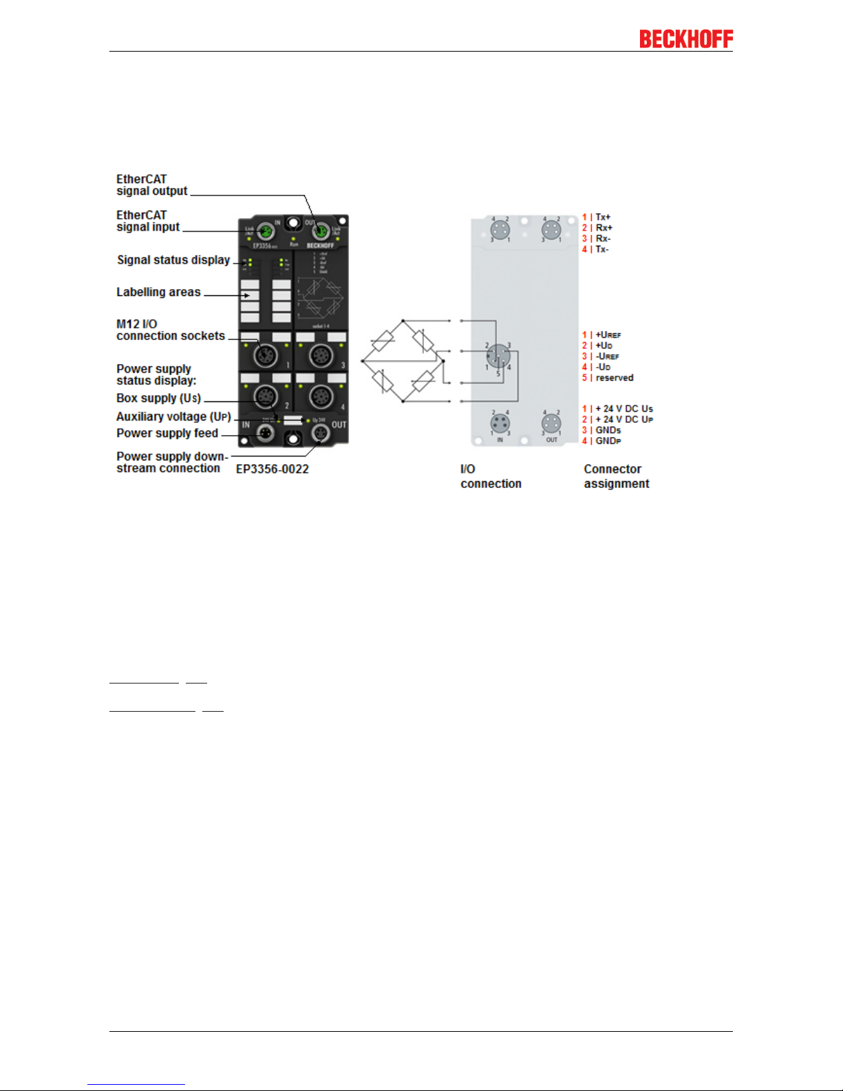
2.1 EP3356-0022 - Introduction
Fig.1: EP3356-0022
1-channel precise load cell analysis (resistor bridge), 24 bit
The EP3356 EtherCAT Box enables direct connection of a resistor bridge or load cell in a 4-wire connection
technology. The ratio between the bridge voltage UD and the supply voltage U
ref
is determined simultaneously
in the input circuit and the final load value is calculated as a process value on the basis of the settings in the
EP3356. With automatic self-calibration (can be deactivated), dynamic filters and distributed clock support,
the EP3356 with measuring cycles of 100µs can be used for fast and precise monitoring of torque or
vibration sensors.
Installation [}27]
Configuration [}48]
Page 9

Product overview
EP3356-0022 9Version: 1.1.0
2.2 EP3356-0022 - Technical data
Technical data EP3356-0022
Number of inputs 2, for 1 resistor bridge in full bridge technology
Signal connection sockets [}46]
M12
Resolution 24Bit, 32bit presentation
Conversion time 0.1ms…250ms, configurable, max. 10,000 samples/s
Nominal voltage 24VDC (-15%/+20%)
Distributed Clocks yes
selectable modes yes (2)
Measuring error <±0.01% for the calculated load value in relation to the final load value
with a 12V feed and 24mV bridge voltage (hence nominal strain gauge
characteristic value of 2mV/V), self-calibration active, 50Hz filter active.
Attention: Due to external influences such as temperature drifts [}10]
and HF-disturbances may possibly occur a not insignificant error!
Measuring range U
D
max. -27mV…+27mV typ. (see note [}89] concerning voltage
measuring recommended: -25mV…+25mV rated voltage
Measuring range U
ref
max. -13.8V…+13.8V typ. (see note [}89] concerning voltage
measuring recommended: -12V…+12V rated voltage
Supported nominal sensitivity all, resolution of parameter: 0.01µV/V
Recommended: 0.5mV/V…4mV/V
Min. strain gauge resistor parallel operation of strain gauges only with suitable strain gauges
recommended
Input filter limit frequency
(hardware)
10kHz low pass (-3dB)
Filter (software) Present 50Hz,
Configurable: 50/60Hz FIR notch filter, IIR low pass 4-fold averager
Internal resistance >200kΩ (U
ref
), > 1MΩ (Ud)
Special features self-calibration, quadruple averager, dynamic filters, fast data sampling,
parallel connection
Sensor supply U
ref
= 10V (supplied by the EP3356)
Current consumption from U
S
(without sensor current)
120mA
Power supply connection feed: 1 x M8 male socket, 4-pin
downstream connection: 1 x M8 female socket, 4-pin
Permissible ambient temperature
during operation
-25°C…+60°C
0°C ... +55°C (according to cULus, see UL Requirements)
Permissible ambient temperature
during storage
-40°C…+85°C
Vibration / shock resistance conforms to EN60068-2-6 / EN60068-2-27
EMC immunity/emission conforms to EN61000-6-2 / EN61000-6-4
Dimensions 126mm x 60mm x 40mm
Weight approx.. 450g
Installation position variable
Protection class IP65, IP66, IP67 (according to EN60529)
Approvals CE, UL
Page 10
Product overview
EP3356-002210 Version: 1.1.0
2.3 Basic principles of strain gauge technology
Basic information on the technological field of "strain gauges/load cells" as metrological instruments is to be
given below. The information is of general nature; it is up to the user to check the extent to which it applies to
his application.
• Strain gauges serve either to directly measure the static (0 to a few Hz) or dynamic (up to several KHz)
elongations, compressions or torsions of a body by being directly fixed to it, or to measure various
forces or movements as part of a sensor (e.g. load cells/force transducers, displacement sensor,
vibration sensors).
• In the case of the optical strain gauge (e.g. Bragg grating), an application of force causes a
proportional change in the optical characteristics of a fiber used as a sensor. Light with a certain
wavelength is fed into the sensor. Depending upon the deformation of the grating, which is laser-cut
into the sensor, due to the mechanical load, part of the light is reflected and evaluated using a suitable
measuring transducer (interrogator).
The commonest principle in the industrial environment is the electrical strain gauge. There are many
common terms for this type of sensor: load cell, weighbridge, etc.
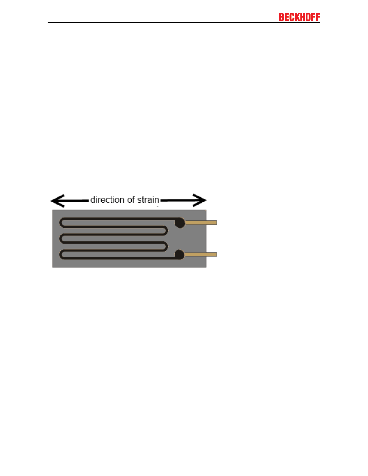
Structure of electrical strain gauges
A strain gauge consists of a carrier material (e.g. stretchable plastic film) with an applied metal film from
which a lattice of electrically conductive resistive material is worked in very different geometrical forms,
depending on the requirements.
Fig.2: Strain gauge
This utilizes a behavior whereby, for example in the case of strain, the length of a metallic resistance network
increases and its diameter decreases, as a result of which its electrical resistance increases proportionally.
ΔR/R = k*ε
ε = Δl/l thereby corresponds to the elongation; the strain sensitivity is called the k-factor. This also gives rise
to the typical track layout inside the strain gauge: the resistor track or course is laid in a meandering pattern
in order to expose the longest possible length to the strain.
Example
The elongation ε = 0.1% of a strain gauge with k-factor 2 causes an increase in the resistance of 0.2%.
Typical resistive materials are constantan (k~2) or platinum tungsten (92PT, 8W with k ~4). In the case of
semiconductor strain gauges a silicon structure is glued to a carrier material. The conductivity is changed
primarily by deformation of the crystal lattice (piezo-resistive effect); k-factors of up to 200 can be achieved.
Measurement of signals
The change in resistance of an individual strain gauge can be determined in principle by resistance
measurement (current/voltage measurement) using a 2/3/4-conductor measurement technique
Page 11
Product overview
EP3356-0022 11Version: 1.1.0
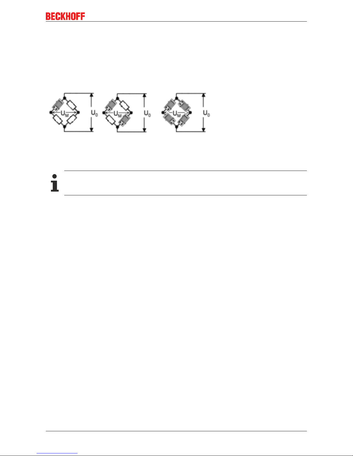
Usually 1/2/4 strain gauges are arranged in a Wheatstone bridge (-> quarter/half/full bridge); the nominal
resistance/impedance R0 of all strain gauges (and the auxiliary resistors used if necessary) is usually
equivalent to R1=R2=R3=R4=R0. Typical values in the non-loaded state are R0 = 120Ω, 350Ω, 700Ω and
1kΩ.
The full bridge possesses the best characteristics such as linearity in the feeding of current/voltage, four
times the sensitivity of the quarter-bridge as well as systematic compensation of disturbing influences such
as temperature drift and creeping. In order to achieve high sensitivity, the 4 individual strain gauges are
arranged on the carrier in such a way that 2 are elongated and 2 are compressed in each case.
Fig.3: quarter, half and full bridge
The measuring bridges can be operated with constant current, constant voltage, or also with AC voltage
using the carrier frequency method.
Measuring procedure
The Beckhoff EL/KL335x Terminals and the EP3356 Box support only the constant excitation
• Full bridge strain gauge at constant voltage (ratiometric measurement)
Since the relative resistance change ΔR is low in relation to the nominal resistance R0, a simplified equation
is given for the strain gauge in the Wheatstone bridge arrangement:
UD/UV = ¼ * (ΔR1-ΔR2+ΔR3-ΔR4)/R
0
ΔR usually has a positive sign in the case of elongation and a minus sign in the case of compression.
A suitable measuring instrument measures the bridge supply voltage UV (or U
Supply
) and the resulting bridge
voltage UD (or U
Bridge
), and forms the quotients from both voltages, i.e. the ratio. After further calculation and
scaling the measured value is output, e.g. in kg. Due to the division of UD and UV the measurement is in
principle independent of changes in the supply voltage.
If the voltages UV and UD are measured simultaneously, i.e. at the same moment, and placed in relation to
each other, then this is referred to as a ratiometric measurement.
The advantage of this is that (with simultaneous measurement!) brief changes in the supply voltage (e.g.
EMC effects) or a generally inaccurate or unstable supply voltage likewise have no effect on the
measurement.
A change in UV by e.g. 1% creates the same percentage change in UD according to the above equation. Due
to the simultaneous measurement of UD and UV the error cancels itself out completely during the division.
4-conductor vs. 6-conductor connection
If supplied with a constant voltage of 5 to 12V a not insignificant current flows of e.g. 12V/350Ω=34.3mA.
This leads not only to dissipated heat, wherein the specification of the strain gauge employed must not be
exceeded, but possibly also to measuring errors in the case of inadequate wiring due to line losses not being
taken into account or compensated.
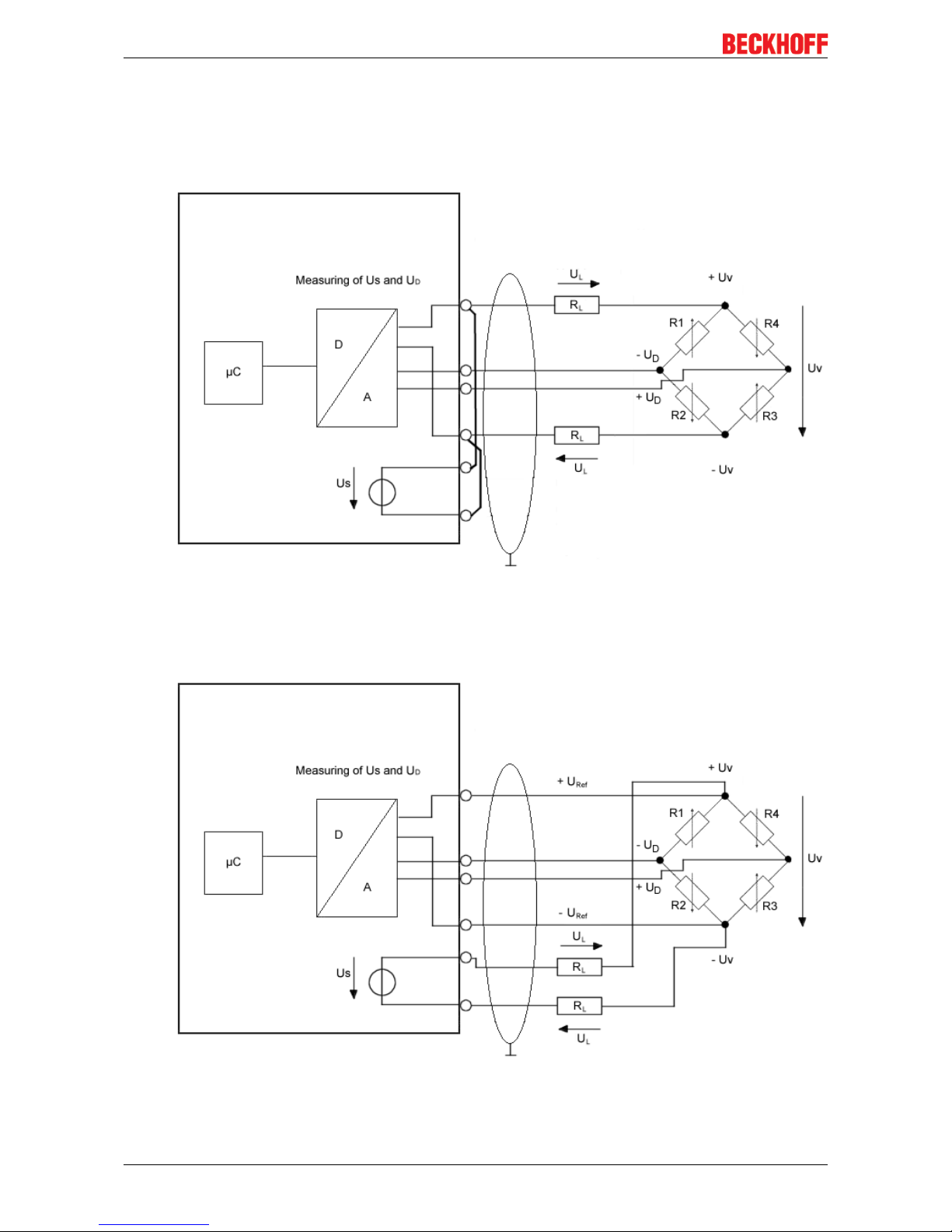
In principle a full bridge can be operated with a 4-conductor connection (2 conductors for the supply UV and 2
for the measurement of the bridge voltage UD).
If, for example, a 25m copper cable (feed + return = 50m) with a cross section q of 0.25mm² is used, this
results in a line resistance of
RL = l/ (κ * q) = 50m / (58S*m/mm² * 0.25mm²) = 3.5Ω
Page 12
Product overview
EP3356-002212 Version: 1.1.0
If this value remains constant, then the error resulting from it can be calibrated out. However, assuming a
realistic temperature change of, for example, 30° the line resistance RL changes by
ΔRL =30° * 3.9 * 10-4 * 3.5Ω = 0.41Ω
In relation to a 350Ω measuring bridge this means a measuring error of > 0.1%.
Fig.4: 4-conductor connection
This can be remedied by a 6-conductor connection, in particular for precision applications (only possible with
EL3356).
Fig.5: 6-conductor connection
Page 13
Product overview
EP3356-0022 13Version: 1.1.0
The supply voltage UV is thereby fed to the strain gauge (= current carrying conductor). The incoming supply
voltage U
ref
is only measured with high impedance directly at the measuring bridge in exactly the same way
as the bridge voltage UD with two currentless return conductors in each case. The conductor-related errors
are hence omitted.
Since these are very small voltage levels of the order of mV and µV, all conductors should be shielded. The
shield must be connected to pin 5 of the M12 connector.
EP3356-0022: No 6-conductor connection necessary
The connection of a strain gauge over 4-conductor with the EP3356-0022 is sufficient because due
to the shorter cable lengths no measurement errors occur.
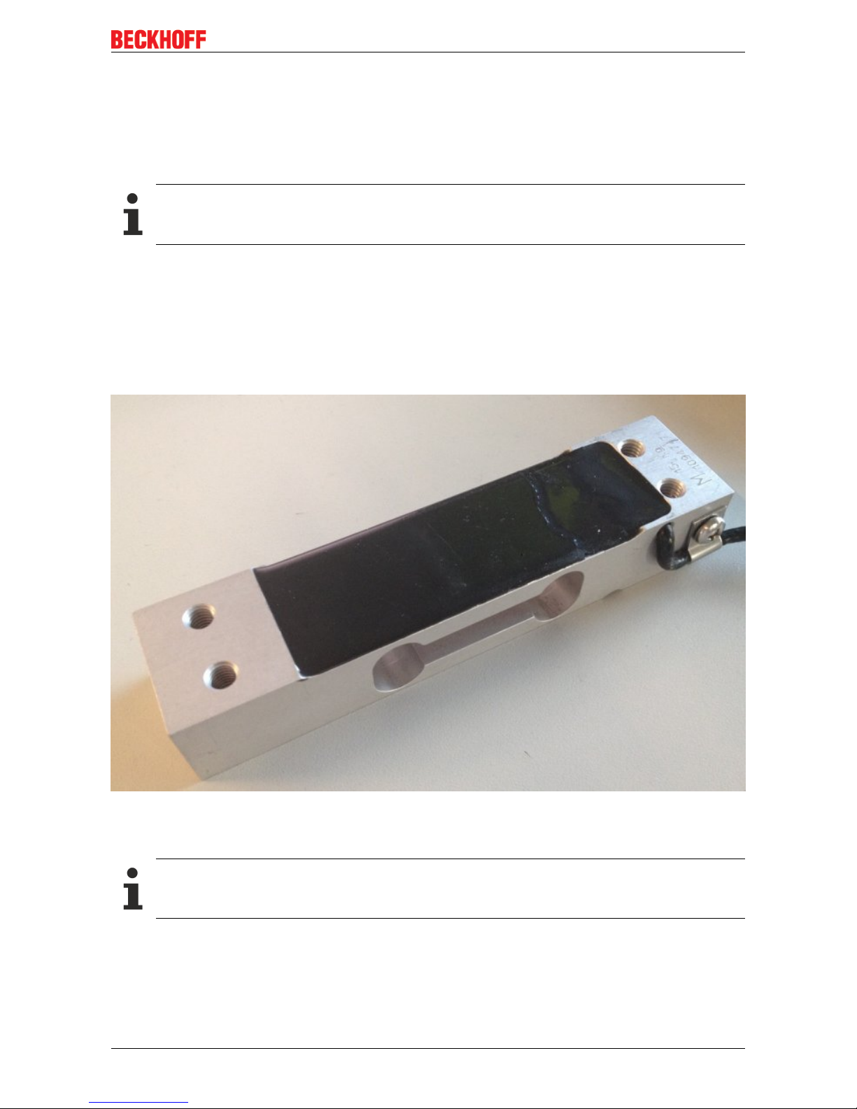
Structure of a load cell with a strain gauge
One application of the strain gauge is the construction of load cells.
This involves gluing strain gauges (full bridges as a rule) to an elastic mechanical carrier, e.g. a doublebending beam spring element, and additionally covered to protect against environmental influences.
The individual strain gauges are aligned for maximum output signals according to the load direction (2 strain
gauges in the elongation direction and 2 in the compression direction).
Fig.6: Example of a load cell
The most important characteristic data of a load cell
Characteristic data
Please enquire tot he sensor manufacturer regarding the exact characteristic data!
Nominal load E
max
Maximum permissible load for normal operation, e.g. 10 kg
Nominal characteristic value mV/V
Page 14

Product overview
EP3356-002214 Version: 1.1.0
The nominal characteristic value 2mV/V means that, with a supply of US=10V and at the full load E
max
of the
load cell, the maximum output voltage UD = 10V * 2mV/V *E = 20mV. The nominal characteristic value is
always a nominal value – a manufacturer’s test report is included with good load cells stating the
characteristic value determined for the individual load cell, e.g. 2.0782mV/V.
Minimum calibration value V
min
This indicates the smallest mass that can be measured without the maximum permissible error of the load
cell being exceeded [RevT].
This value is represented either by the equation V
min
= E
max
/ n (where n is an integer, e.g. 10000), or in % of
E
max
(e.g. 0.01).
This means that a load cell with E
max
= 10kg has a maximum resolution of
V
min
= 10kg / 10000 = 1g or V
min
= 10kg * 0.01% = 1g.
Accuracy class according to OIML R60
The accuracy class is indicated by a letter (A, B, C or D) and an additional number, which encodes the scale
interval d with a maximum number n
max
(*1000); e.g. C4 means Class C with maximally 4000d scale
intervals.
The classes specify a maximum and minimum limit for scale intervals d:
• A: 50,000 – unlimited
• B: 5000 – 100,000
• C: 500 – 10,000
• D: 500 – 1000
The scale interval n
max
= 4000d states that, with a load cell with a resolution of V
min
= 1g, a calibratable set of
scales can be built that has a maximum measuring range of 4000d * V
min
= 4kg. Since V
min
is thereby a
minimum specification, an 8kg set of scales could be built – if the application allows – with the same load
cell, wherein the calibratable resolution would then fall to 8kg/4000d=2g. From another point of view the
scale interval n
max
is a maximum specification; hence, the above load cell could be used to build a set of
scales with a measuring range of 4kg, but a resolution of only 2000 divisions = 2g, if this is adequate for the
respective application. Also the classes differ in certain error limits related to non-repeatability/creep/TC
Accuracy class according to PTB
The European accuracy classes are defined in an almost identical way (source: PTB).
Class Calibration values Minimum load Max/e
Minimum
value
Maximum
value
|
Fine scales
0.001g <= e 100 e 50000
||
Precision scales
g <= e <=0.05g
g <= e
20 e
50 e
100
5000
100000
100000
|||
Commercial scales
g <= e <=2g
g <= e
20 e
20 e
100
500
10000
10000
||||
Coarse scales
5g <= e 10 e 100 1000
Minimum application range or minimum measuring range in % of rated load
This is the minimum measuring range/measuring range interval, which a calibratable load cell/set of scales
must cover.
Example: above load cell E
max
= 10kg; minimum application range e.g. 40% E
max
Page 15
Product overview
EP3356-0022 15Version: 1.1.0
The used measuring range of the load cell must be at least 4kg. The minimum application range can lie in
any range between E
min
and E
max
, e.g. between 2kg and 6kg if a tare mass of 2kg already exists for
structural reasons. A relationship between n
max
and V
min
is thereby likewise apparent: 4000 * 1g = 4kg .
There are further important characteristic values, which are for the most part self-explanatory and need not
be discussed further here, such as nominal characteristic value tolerance, input/output resistance,
recommended supply voltage, nominal temperature range etc.
Parallel connection of strain gauges
It is usual to distribute a load mechanically to several strain gauge load cells at the same time. Hence, for
example, the 3-point bearing of a silo container on 3 load cells can be realized. Taking into account wind
loads and loading dynamics, the total loading of the silo including the dead weight of the container can thus
be measured. The mechanically parallel-connected load cells are usually also electrically connected in
parallel and connect at two arbitrarily M12 sockets of EP3356-0022 (see figure below). To this end the
following must be observed:
• the load cells must be matched to each other and approved by the manufacturer for this mode of
operation
• the impedance of the load cells must be such that the current feed capability of the transducer
electronics (max. 350mA) is not overloaded.
Fig.7: Parallel connection of strain gauges
Sources of error/disturbance variables
Inherent electrical noise of the load cell
Electrical conductors exhibit so-called thermal noise (thermal/Johnson noise), which is caused by irregular
temperature-dependent movements of the electrons in the conductor material. The resolution of the bridge
signal is already limited by this physical effect. The rms value en of the noise can be calculated by en =
√4kTRB
In the case of a load cell with R0 = 350Ω at an ambient temperature T = 20°C (= 293K) and a bandwidth of
the measuring transducer of 50Hz (and Boltzmann constant k = 1.38 * 10
-23
J/K), the rms en= 16.8nV. The
peak-peak noise epp is thus approx. epp ~ 4* en = 67.3nV.
Example:
In relation to the maximum output voltage U
out-max
of a bridge with 2mV/V and Us = 5V, this corresponds to
U
out-max
= 5V * 2mV/V = 10mV. (For the nominal load) this results in a maximum resolution of
10mV/67.3nV = 148588digits. Converted into bit resolution: ln(148588)/ln(2) = 17bits. Interpretation: a
higher digital measuring resolution than 17bits is thus inappropriate for such an analog signal in the first
Page 16

Product overview
EP3356-002216 Version: 1.1.0
step. If a higher measuring resolution is used, then additional measures may need to be taken in the
evaluation chain in order to obtain the higher information content from the signal, e.g. hardware low-pass
filter or software algorithms.
This resolution applies alone to the measuring bridge without any further interferences. The resolution of the
measuring signal can be increased by reducing the bandwidth of the measuring unit.
If the strain gauge is glued to a carrier (load cell) and wired up, both external electrical disturbances (e.g.
thermovoltage at connection points) and mechanical vibrations in the vicinity (machines, drives, transformers
(mechanical and audible 50Hz vibration due to magnetostriction etc.)) can additionally impair the result of
measurement.
Creep
Under a constant load, spring materials can further deform in the load direction. This process is reversible,
but it generates a slowly changing measured value during the static measurement. In an ideal case the error
can be compensated by constructive measures (geometry, adhesives).
Hysteresis
If even elongation and compression of the load cell take place, then the output voltage does not follow
exactly the same curve, since the deformation of the strain gauge and the carrier may be different due to the
adhesive and its layer thickness.
Temperature drift (inherent heating, ambient temperature)
Relatively large currents can flow in strain gauge applications, e.g. I=US/R0=10V/350Ω=26mA. The
power dissipation at the sensor is thus PV=U*I=10V*26mA=260mW. Depending on application/carrier
material (= cooling) and ambient temperature, a not insignificant error can arise that is termed apparent
elongation. The sensor manufacturers integrate suitable compensation elements in their strain gauges.
Inadequate circuit technology
As already shown, a full bridge may be able (due to the system) to fully compensate non-linearity, creep and
temperature drift. Wiring-related measuring errors are avoided by the 6-conductor connection.
References
Some organizations are listed below that provide the specifications or documents for the technological field
of weighing technology:
• OIML (ORGANISATION INTERNATIONALE DE MÉTROLOGIE LÉGALE) www.oiml.org/en
• PTB - Physikalisch-Technischen Bundesanstalt www.ptb.de/cms/
• www.eichamt.de
• WELMEC - European cooperation in legal metrology www.welmec.org
• DAkkS – Deutsche Akkreditierungsstelle www.dakks.de
• Fachgemeinschaft Waagen (AWA) im Verband Deutscher Maschinen- und Anlagenbau VDMA
www.vdma.org
Page 17

Basics of communication
EP3356-0022 17Version: 1.1.0
3 Basics of communication
3.1 EtherCAT basics
Basic information on the EtherCAT fieldbus can be found in the EtherCAT system documentation.
3.2 Watchdog setting
General information on watchdog settings
The ELxxxx Terminals and EPxxxx Box Modules are equipped with a safety device (watchdog) that switches
the outputs to a safe state after a time that can be preset, for example in the case of interrupted process data
traffic, or to OFF, for example depending on device and setting.
The EtherCAT Slave Controller (ESC) has two watchdogs:
• SM watchdog (default: 100 ms)
• PDI watchdog (default: 100 ms)
SM Watchdog (SyncManagerWatchdog)
The SyncManager watchdog is reset after each successful EtherCAT process data communication with the
terminal/box. If no EtherCAT process data communication takes place with the terminal/box for longer than
the set and activated SM watchdog time, e.g. in the event of a line interruption, the watchdog is triggered and
the outputs are set to FALSE. The OP status of the terminal/box is unaffected by this. The watchdog is only
reset after a successful EtherCAT process data access. Set the monitoring time as specified below.
The SyncManager watchdog monitors correct and timely process data communication with the ESC from the
EtherCAT side.
PDI watchdog (process data watchdog)
If no PDI communication with the EtherCAT slave controller (ESC) takes place for longer than the set and
activated PDI watchdog time, this watchdog is triggered.
PDI (Process Data Interface) is the internal interface between the ESC and local processors in the EtherCAT
slave, for example. The PDI watchdog can be used to monitor this communication for failure.
The PDI watchdog monitors correct and timely process data communication with the ESC but from the
application side.
The SM and PDI watchdogs should be set separately for each slave in the TwinCAT System Manager:
Page 18
Basics of communication
EP3356-002218 Version: 1.1.0
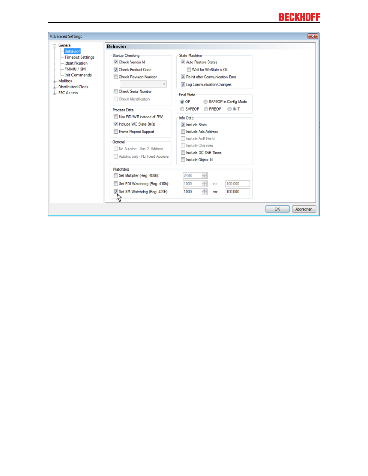
Fig.8: EtherCAT tab --> Advanced settings --> Behavior --> Watchdog
Comments:
• The multiplier applies to both watchdogs.
• Each watchdog has its own timer setting, which together with the multiplier results in a time.
• Important: The multiplier/timer setting is loaded into the slave on start-up, if the corresponding
checkbox is ticked. If the checkbox is not ticked, no download takes place, and the ESC setting
remains unchanged.
Multiplier
Both watchdogs receive their pulses from the local terminal/box clock, divided by the watchdog multiplier.
1/25 MHz * (watchdog multiplier + 2) = 100µs (for default setting of 2498 for the multiplier)
The standard setting of 1000 for the SM watchdog corresponds to a release time of 100 ms.
The value in multiplier + 2 corresponds to the number of basic 40ns ticks representing a watchdog tick.
The multiplier can be modified in order to adjust the watchdog time over a larger range.
Example "Set SM watchdog"
This checkbox enables manual setting of the watchdog times. If the outputs are set and the EtherCAT
communication is interrupted, the SM watchdog is triggered after the set time and the outputs are deleted.
This setting can be used for adapting a terminal to a slower EtherCAT master or long cycle times. The
default SM watchdog setting is 100 ms. The setting range is from 0 to 65535. Together with a multiplier in a
range from 1 to 65535, this covers a watchdog period of 0 to ~170 seconds.
Calculation
Multiplier = 2498 → watchdog base time = 1 / 25MHz * (2498 + 2) = 0.0001seconds = 100µs
SM watchdog = 10000 → 10000 * 100µs = 1second watchdog monitoring time
Page 19

Basics of communication
EP3356-0022 19Version: 1.1.0
CAUTION
Caution! Unintended behavior of the system is possible!
The function for switching off of the SM watchdog via SM watchdog = 0 is only implemented in terminals
from version -0016. In previous versions this operating mode should not be used.
CAUTION
Caution! Damage to the equipment and unintended behavior of the system is possible!
If the SM watchdog is activated and a value of 0 is entered the watchdog switches off completely. This is
watchdog deactivation! Outputs are then NOT set to a safe state, in the event of an interruption in communication!
Outputs in SAFEOP
Watchdog monitoring is activated by default. It sets the outputs in the module to a safe state (e.g.
OFF), depending on the SAFEOP and OP settings, and depending on the device and its settings. If
this is prevented due to deactivation of watchdog monitoring in the module, outputs can be switched
or remain set in device state SAFEOP.
Page 20
Basics of communication
EP3356-002220 Version: 1.1.0
3.3 EtherCAT State Machine
The state of the EtherCAT slave is controlled via the EtherCAT State Machine (ESM). Depending upon the
state, different functions are accessible or executable in the EtherCAT slave. Specific commands must be
sent by the EtherCAT master to the device in each state, particularly during the bootup of the slave.
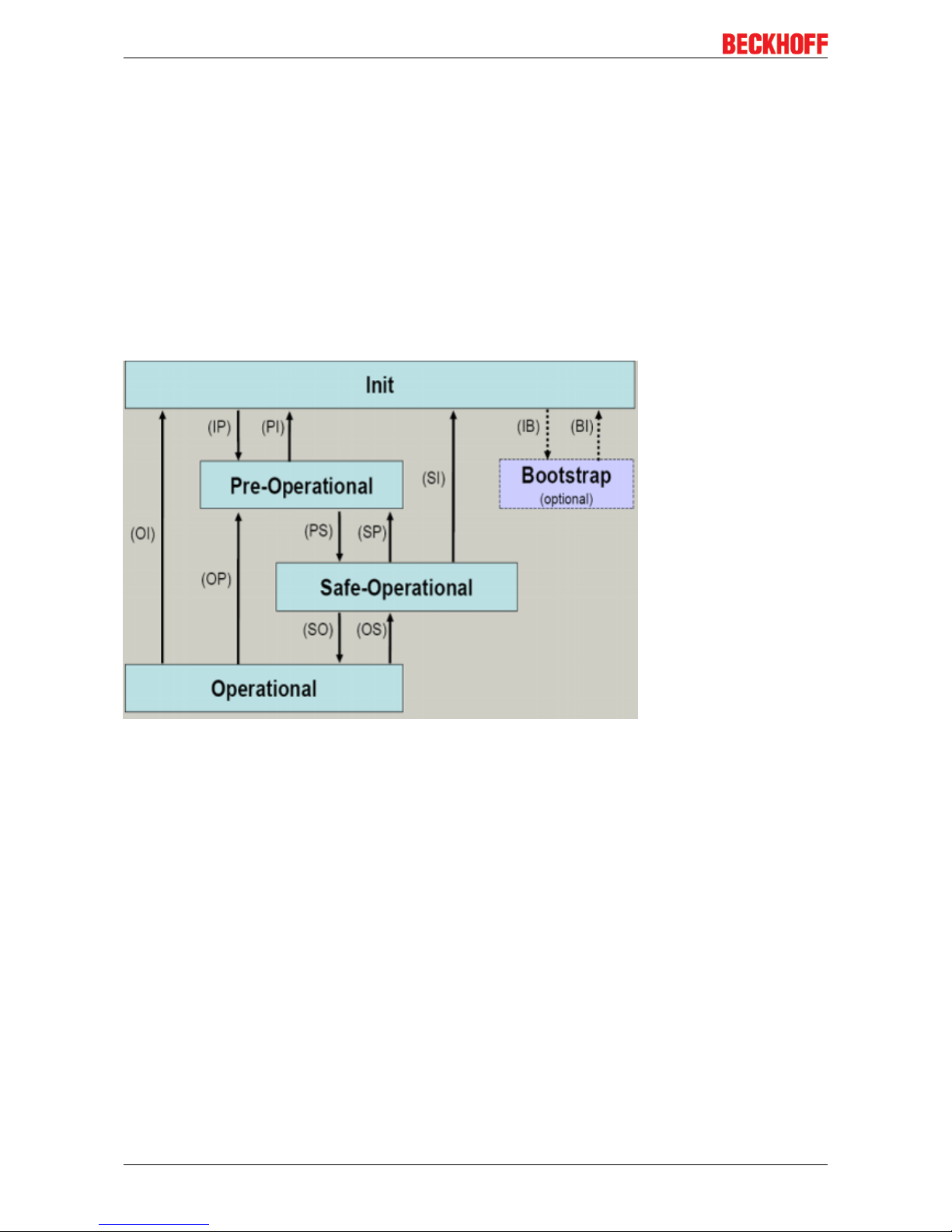
A distinction is made between the following states:
• Init
• Pre-Operational
• Safe-Operational and
• Operational
• Boot
The regular state of each EtherCAT slave after bootup is the OP state.
Fig.9: EtherCAT State Machine
Init
After switch-on the EtherCAT slave in the Init state. No mailbox or process data communication is possible.
The EtherCAT master initializes sync manager channels 0 and 1 for mailbox communication.
Pre-Operational (Pre-Op)
During the transition between Init and Pre-Op the EtherCAT slave checks whether the mailbox was initialized
correctly.
In Pre-Op state mailbox communication is possible, but not process data communication. The EtherCAT
master initializes the sync manager channels for process data (from sync manager channel 2), the FMMU
channels and, if the slave supports configurable mapping, PDO mapping or the sync manager PDO
assignment. In this state the settings for the process data transfer and perhaps terminal-specific parameters
that may differ from the default settings are also transferred.
Safe-Operational (Safe-Op)
During transition between Pre-Op and Safe-Op the EtherCAT slave checks whether the sync manager
channels for process data communication and, if required, the distributed clocks settings are correct. Before
it acknowledges the change of state, the EtherCAT slave copies current input data into the associated DPRAM areas of the EtherCAT slave controller (ECSC).
Page 21

Basics of communication
EP3356-0022 21Version: 1.1.0
Mailbox and process data communication is possible in the Safe-Op state, but the slave keeps its outputs in
the safe state. However, the input data are cyclically updated.
Operational (Op)
Before the EtherCAT master switches the EtherCAT slave from Safe-Op to Op it must transfer valid output
data.
In the Op state the slave copies the output data of the masters to its outputs. Process data and mailbox
communication is possible.
Boot
In the Boot state the slave firmware can be updated. The Boot state can only be reached via the Init state.
In the Boot state mailbox communication via the file access over EtherCAT (FoE) protocol is possible, but no
other mailbox communication and no process data communication.
Page 22

Basics of communication
EP3356-002222 Version: 1.1.0
3.4 CoE interface
General description
The CoE interface (CANopen over EtherCAT) is used for parameter management of EtherCAT devices.
EtherCAT slaves or the EtherCAT master manage fixed (read only) or variable parameters which they
require for operation, diagnostics or commissioning.
CoE parameters are arranged in a table hierarchy. In principle, the user has read access via the fieldbus.
The EtherCAT master (TwinCAT System Manager) can access the local CoE lists of the slaves via
EtherCAT in read or write mode, depending on the properties.
Different CoE parameter types are possible, including string (text), integer numbers, Boolean values or larger
byte fields. They can be used to describe a wide range of features. Examples of such parameters include
manufacturer ID, serial number, process data settings, device name, calibration values for analog
measurement or passwords.
Organization takes place on 2 levels by means of hexadecimal numbering: the (main) index is named first,
then the subindex. The value ranges are:
• Index 0 to 65535
• Subindex: 0…255
A parameter localized in this way is normally written as 0x8010:07, with preceding "0x" to identify the
hexadecimal numerical range and a colon between index and subindex.
The relevant ranges for EtherCAT fieldbus users are:
• 0x1000: This is where fixed identity information for the device is stored, including name, manufacturer,
serial number etc., plus information about the current and available process data configurations.
• 0x8000: This is where the operational and functional parameters for all channels are stored, such as
filter settings or output frequency.
Other important ranges are:
• 0x4000: In some EtherCAT devices the channel parameters are stored here (as an alternative to the
0x8000 range).
• 0x6000: Input PDOs ("input" from the perspective of the EtherCAT master)
• 0x7000: Output PDOs ("output" from the perspective of the EtherCAT master)
Availability
Not every EtherCAT device must have a CoE list. Simple I/O modules without dedicated processor
usually have no variable parameters and therefore no CoE list.
If a device has a CoE list, it is shown in the TwinCAT System Manager as a separate tab with a listing of the
elements:
Page 23

Basics of communication
EP3356-0022 23Version: 1.1.0
Fig.10: CoE-Online tab
The CoE objects from 0x1000 to 0x1600, which are available in the example device "EL2502", can be seen
in the above figure; the subindices from 0x1018 are expanded.
Data management
Some parameters, particularly the setting parameters of the slave, are configurable and writeable. This can
be done in write or read mode
• via the System Manager (figure above) by clicking. This is useful for commissioning of the system/
slaves. Click on the row of the index to be parameterized and enter a value in the SetValue dialog.
• from the control system/PLC via ADS, e.g. through function blocks from the TcEtherCAT.lib library This
is recommended for modifications while the system is running or if no System Manager or operating
staff are available.
Data management
If CoE parameters on the slave are changed online, this is saved fail-safe in the device (EEPROM)
in Beckhoff devices. This means that the changed CoE parameters are still retained after a restart.
The situation may be different with other manufacturers.
Startup list
Startup list
Changes in the local CoE list of the terminal are lost if the terminal is replaced. If a terminal is replaced with a new Beckhoff terminal, it will have the factory settings. It is therefore advisable to link
all changes in the CoE list of an EtherCAT slave with the Startup list of the slave, which is processed whenever the EtherCAT fieldbus is started. In this way a replacement EtherCAT slave can
automatically be parameterized with the specifications of the user.
If EtherCAT slaves are used which are unable to store local CoE values permanently, the Startup
list must be used.
Recommended approach for manual modification of CoE parameters
• Make the required change in the System Manager. The values are stored locally in the EtherCAT slave
Page 24

Basics of communication
EP3356-002224 Version: 1.1.0
• If the value is to be stored permanently, enter it in the Startup list. The order of the Startup entries is
usually irrelevant.
Fig.11: Startup list in the TwinCAT System Manager
The Startup list may already contain values that were configured by the System Manager based on the ESI
specifications. Additional application-specific entries can be created.
Online/offline directory
While working with the TwinCAT System Manager, a distinction has to be made whether the EtherCAT
device is "available", i.e. switched on and linked via EtherCAT and therefore online, or whether a
configuration is created offline without connected slaves.
In both cases a CoE directory is visible according to the figure "CoE-Online tab", but the connectivity is
displayed as offline/online.
• If the slave is offline
◦ the offline list from the ESI file is displayed. In this case modifications are not meaningful or
possible.
◦ the configured status is shown under Identity
◦ no firmware or hardware version is displayed, since these are features of the physical device.
◦ Offline is shown in red
Page 25

Basics of communication
EP3356-0022 25Version: 1.1.0
Fig.12: Offline list
• If the slave is online
◦ the actual current slave directory is read. This may take several seconds, depending on the size
and cycle time.
◦ the actual identity is displayed
◦ the firmware and hardware version of the equipment according to the electronic information is
displayed.
◦ Online is shown in green
Fig.13: Online list
Page 26

Basics of communication
EP3356-002226 Version: 1.1.0
Channel-based order
The CoE directory is located in EtherCAT devices that usually encompass several functionally equivalent
channels. e.g. a 4-channel 0 – 10 V analog input terminal also has 4 logical channels and thus 4 identical
sets of parameter data for the channels. In order to avoid having to list each channel in the documentation,
the placeholder "n" tends to be used for the individual channel numbers.
In the CoE system 16 indices, each with 255 subindices, are generally sufficient for representing all channel
parameters. The channel-based order is therefore arranged in 16
dec
/10
hex
steps. The parameter range
0x8000 exemplifies this:
• Channel 0: parameter range 0x8000:00 ... 0x800F:255
• Channel 1: parameter range 0x8010:00 ... 0x801F:255
• Channel 2: parameter range 0x8020:00 ... 0x802F:255
• …
This is generally written as 0x80n0. Detailed information on the CoE interface can be found in the EtherCAT
system documentation on the Beckhoff website.
3.5 Distributed Clock
The distributed clock represents a local clock in the EtherCAT slave controller (ESC) with the following
characteristics:
• Unit 1ns
• Zero point 1.1.2000 00:00
• Size 64bit (sufficient for the next 584years; however, some EtherCAT slaves only offer 32-bit support,
i.e. the variable overflows after approx. 4.2seconds)
• The EtherCAT master automatically synchronizes the local clock with the master clock in the EtherCAT
bus with a precision of <100ns
For detailed information please refer to the EtherCAT system description.
Page 27
Mounting and Cabling
EP3356-0022 27Version: 1.1.0
4 Mounting and Cabling
4.1 Mounting
4.1.1 Dimensions
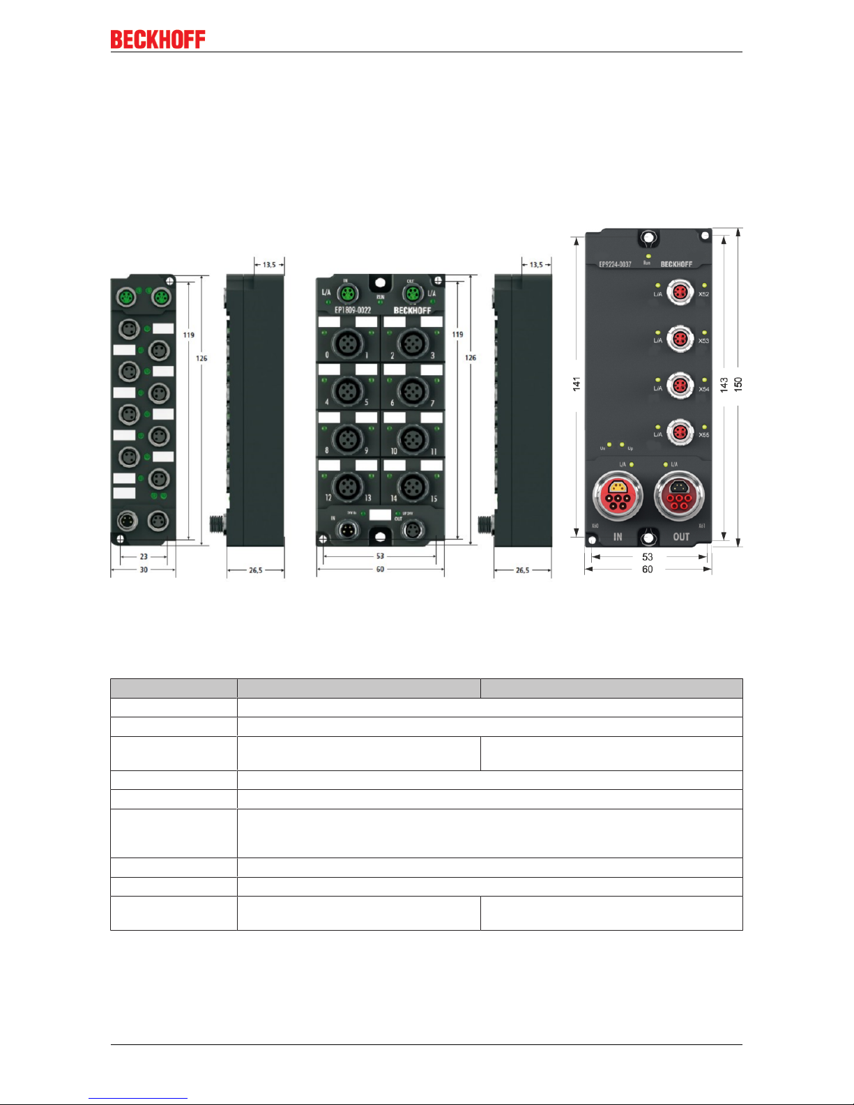
Fig.14: Dimensions of the EtherCAT Box Modules
All dimensions are given in millimeters.
Housing properties
EtherCAT Box lean body wide bodies
Housing material PA6 (polyamide)
Casting compound Polyurethane
Mounting two fastening holes Ø3mm for M3 two fastening holes Ø3mm for M3
two fastening holes Ø4.5mm for M4
Metal parts Brass, nickel-plated
Contacts CuZn, gold-plated
Power feed through max. 4A (M8)
max. 16A (7/8“)
max. 15.5A (B17 5G 1.5mm2)
Installation position variable
Protection class IP65, IP66, IP67 (conforms to EN 60529) when screwed together
Dimensions
(HxWxD)
app. 126 x 30 x 26.5mm app. 126 x 60 x 26,5mm
app. 150 x 60 x 26.5mm (without 7/8", B17)
Page 28
Mounting and Cabling
EP3356-002228 Version: 1.1.0
4.1.2 Fixing
Note or pointer
While mounting the modules, protect all connectors, especially the IP-Link, against contamination!
Only with connected cables or plugs the protection class IP67 is guaranteed! Unused connectors
have to be protected with the right plugs! See for plug sets in the catalogue.
Modules with narrow housing are mounted with two M3 bolts.
Modules with wide housing are mounted with two M3 bolts to the fixing holes located at the corners or
mounted with two M4 bolts to the fixing holes located centrally.
The bolts must be longer than 15 mm. The fixing holes of the modules are not threaded.
When assembling, remember that the fieldbus connectors increases the overall height. See chapter
accessories.
Mounting Rail ZS5300-0001
The mounting rail ZS5300-0001 (500 mm x 129 mm) allows the time saving assembly of modules.
The rail is made of stainless steel, 1.5 mm thick, with already pre-made M3 threads for the modules. The rail
has got 5.3 mm slots to mount it via M5 screws to the machine.
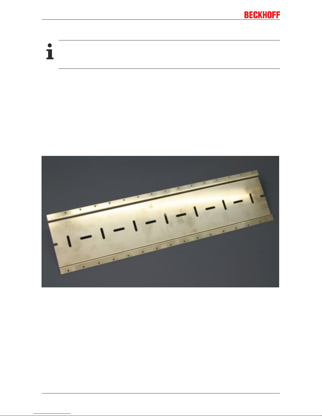
Fig.15: Mounting Rail ZS5300-000
The mounting rail is 500 mm long, that way 15 narrow modules can be mounted with a distance of 2 mm
between two modules. The rail can be cut to length for the application.
Mounting Rail ZS5300-0011
The mounting rail ZS5300-0011 (500 mm x 129 mm) has in addition to the M3 treads also pre-made M4
treads to fix 60 mm wide modules via their middle holes.
Up to 14 narrow or 7 wide modules may be mixed mounted.
Page 29
Mounting and Cabling
EP3356-0022 29Version: 1.1.0
4.1.3 Nut torque for connectors
M8 connectors
It is recommended to pull the M8 connectors tight with a nut torque of 0.4 Nm. When using the torque control
screwdriver ZB8800 is also a max. torque of 0.5Nm permissible.
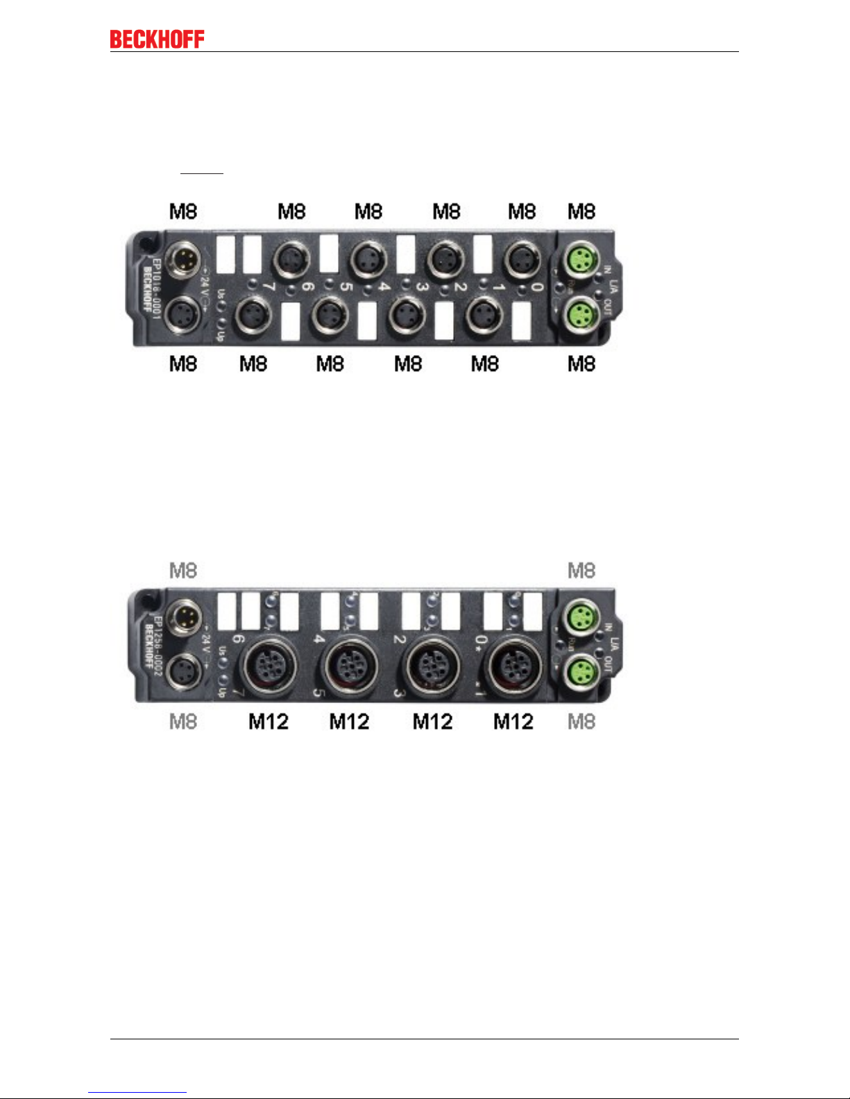
Fig.16: EtherCAT Box with M8 connectors
M12 connectors
It is recommended to pull the M12 connectors tight with a nut torque of 0.6 Nm.
Fig.17: EtherCAT Box with M8 and M12 connectors
Page 30
Mounting and Cabling
EP3356-002230 Version: 1.1.0
7/8" plug connectors
We recommend fastening the 7/8" plug connectors with a torque of 1.5Nm.
Fig.18: 7/8" plug connectors
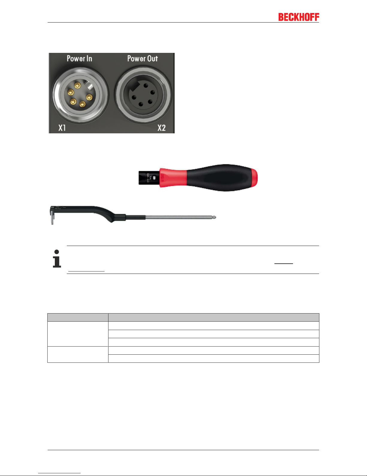
Torque socket wrenches
Fig.19: ZB8801 torque socket wrench
Ensure the right torque
Use the torque socket wrenches available by Beckhoff to pull the connectors tight (ZB8800,
ZB8801-0000)!
4.1.4 Additional checks
The boxes have undergone the following additional tests:
Verification Explanation
Vibration 10 frequency runs in 3 axes
5Hz < f < 60Hz displacement 0.35mm, constant amplitude
60.1Hz < f < 500Hz acceleration 5g, constant amplitude
Shocks 1000 shocks in each direction, in 3 axes
35g, 11ms
Page 31

Mounting and Cabling
EP3356-0022 31Version: 1.1.0
4.2 EtherCAT
4.2.1 EtherCAT connection
For the incoming and ongoing EtherCAT connection,
• the EtherCAT Box (EPxxxx) has two M8 sockets, marked in green
• the Coupler Box (FBB-x110) has two M12 sockets
Fig.20: EtherCAT Box: M8, 30mm housing
Fig.21: EtherCAT Box: M860mm housing (example: EP9214)
Fig.22: Coupler Box: M12
Assignment
There are various different standards for the assignment and colors of connectors and cables for Ethernet/
EtherCAT.
Page 32

Mounting and Cabling
EP3356-002232 Version: 1.1.0
Ethernet/EtherCAT Plug connector Cable Standard
Signal Description M8 M12 RJ45
1
ZB9010, ZB9020,
ZB9030, ZB9032,
ZK1090-6292,
ZK1090-3xxx-xxxx
ZB9031 and old versions
of ZB9030, ZB9032,
ZK1090-3xxx-xxxx
TIA-568B
Tx + Transmit Data+ Pin 1 Pin 1 Pin 1 yellow
2
orange/white
3
white/orange
Tx - Transmit Data- Pin 4 Pin 3 Pin 2 orange
2
orange
3
orange
Rx + Receive Data+ Pin 2 Pin 2 Pin 3 white
2
blue/white
3
white/green
Rx - Receive Data- Pin 3 Pin 4 Pin 6 blue
2
blue
3
green
Shield Shield Housing Shroud Screen Screen Screen
1
) colored markings according to EN 61918 in the four-pin RJ45 connector ZS1090-0003
2
) wire colors according to EN 61918
3
) wire colors
Assimilation of color coding for cable ZB9030, ZB9032 and ZK1090-3xxxx-xxxx (with
M8 connectors)
For unification the prevalent cables ZB9030, ZB9032 and ZK1090-3xxx-xxxx this means the pre assembled cables with M8 connectors were changed to the colors of EN61918 (yellow, orange, white,
blue).So different color coding exists. But the electrical properties are absolutely identical.
EtherCAT connector
The following connectors can be supplied for use in Beckhoff EtherCAT systems.
Name Connector Comment
ZS1090-0003 RJ45 four-pole, IP20, field-configurable
ZS1090-0004 M12, male four-pin, IP67, for field assembly
ZS1090-0005 RJ45 eight-pole, IP20, field-configurable, suitable for gigabit Ethernet
ZS1090-0006 M8 plug connector four-pole, IP67, field-configurable, for cable type ZB903x
ZS1090-0007 M8 socket four-pole, IP67, field-configurable, for cable type ZB903x
ZS1090-1006 M8 plug connector four-pole, IP67, field-configurable up to OD=6.5mm
ZS1090-1007 M8 socket four-pole, IP67, field-configurable up to OD=6.5mm
4.2.2 EtherCAT - Fieldbus LEDs
Fig.23: EtherCAT-LEDs
Page 33

Mounting and Cabling
EP3356-0022 33Version: 1.1.0
LED display
LED Display Meaning
IN L/A off no connection to the preceding EtherCAT module
Lit LINK: connection to the preceding EtherCAT module
flashing ACT: Communication with the preceding EtherCAT module
OUT L/A off no connection to the following EtherCAT module
Lit LINK: connection to the following EtherCAT module
flashing ACT: Communication with the following EtherCAT module
Run off Status of the EtherCAT module is Init
flashes quickly Status of the EtherCAT module is pre-operational
flashes slowly Status of the EtherCAT module is safe-operational
Lit Status of the EtherCAT module is operational
EtherCAT statuses
The various statuses in which an EtherCAT module may be found are described in the Basic System Documentation for EtherCAT, which is available for download from our website (www.beck-
hoff.com) under Downloads.
Page 34

Mounting and Cabling
EP3356-002234 Version: 1.1.0
4.3 Power supply
4.3.1 Power Connection
The feeding and forwarding of supply voltages is done via two M8 connectors at the bottom end of the
modules:
• IN: left M8 connector for feeding the supply voltages
• OUT: right M8 connector for forwarding the supply voltages
Fig.24: EtherCAT Box, Connectors for power supply
Fig.25: Pin assignment M8, Power In and Power Out
Table1: PIN assignment
Pin Voltage
1 Control voltage Us, +24V
DC
2 Auxiliary voltage Up, +24V
DC
3 GNDs* *) may be connected internally to each other depending on the module: see specific
module descriptions
4 GNDp*
The pins M8 connectors carry a maximum current of 4A.
Two LEDs display the status of the supply voltages.
NOTE
Don't confuse the power connectors with the EtherCAT connectors!
Never connect the power cables (M8, 24VDC) with the green marked EtherCAT sockets of the EtherCAT
Box Modules! This can damage the modules!
Control voltage Us: 24V
DC
Power is supplied to the fieldbus, the processor logic, the inputs and the sensors from the 24VDC control
voltage Us. The control voltage is electrically isolated from the fieldbus circuitry.
Page 35

Mounting and Cabling
EP3356-0022 35Version: 1.1.0
Auxiliary voltage Up 24V
DC
The Auxiliary voltage Up supplies the digital outputs; it can be brought in separately. If the load voltage is
switched off, the fieldbus functions and the power supply and functionality of the inputs are retained.
Redirection of the supply voltages
The IN and OUT power connections are bridged in the module (not IP204x-Bxxx and IE204x). The supply
voltages Us and Up can thus easily be transferred from EtherCATBox to EtherCATBox.
NOTE
Pay attention to the maximum permissible current!
Pay attention also for the redirection of the supply voltages Us and Up, the maximum permissible current
for M8 connectors of 4A must not be exceeded!
Page 36

Mounting and Cabling
EP3356-002236 Version: 1.1.0
Supply via EP92x4-0023 PowerBox modules
If the machine requires higher current or if the EtherCAT Box Modules are installed far away from the control
cabinet with included power supply, the usage of four cannel power distribution modules EP9214 or EP9224
(with integrated data logging, see www.beckhoff.com/EP9224) is recommended.
With these modules intelligent power distribution concepts with up to 2x16A and a maximum of 2.5mm²
cable cross-section can be realized.
Fig.26: EP92x4-0023, Connectors for Power In and Power Out
Fig.27: Pin assignment 7/8”, Power In and Power Out
Page 37

Mounting and Cabling
EP3356-0022 37Version: 1.1.0
Electrical isolation
Digital modules
In the digital input/output modules, the grounds of the control voltage (GNDs) and the auxiliary voltage
(GNDp) are connected to each other!
Check this at the documentation of each used EtherCAT Box.
Analog modules
In the analog input/output modules the grounds of the control voltage (GNDs) and the auxiliary voltage
(GNDp) are separated from each other in order to ensure electrical isolation of the analog signals from the
control voltage.
In some of the analog modules the sensors or actuators are supplied by Up - this means, for instance, that in
the case of 0...10 V inputs, any reference voltage (0...30 V) may be connected to Up; this is then available to
the sensors (e.g. smoothed 10 V for measuring potentiometers).
Details of the power supply may be taken from the specific module descriptions.
NOTE
Electrical isolation may be cancelled!
If digital and analog fieldbus boxes are connected directly via four-core power leads, the analog signals in
the fieldbus boxes may be no longer electrically isolated from the control voltage!
4.3.2 Status LEDs for power supply
Fig.28: Status LEDs for power supply
LED display
LED Display Meaning
Us (Control voltage) off The power supply voltage Us is not present
green illuminated The power supply voltage Us is present
red illuminated Because of overload (current>0.5A) the sensor supply
generated from power supply voltage Us was switched off for
all sensors fed from this.
Up (Auxiliary voltage) off The power supply voltage Up is not present
green illuminated The power supply voltage Up is present
Page 38

Mounting and Cabling
EP3356-002238 Version: 1.1.0
4.3.3 Power cable conductor losses M8
The ZK2020-xxxx-yyyy power cables should not exceed the total length of 15m at 4A (with continuation).
When planning the cabling, note that at 24V nominal voltage, the functionality of the module can no longer
be assured if the voltage drop reaches 6V. Variations in the output voltage from the power supply unit must
also be taken into account.
Fig.29: Power cable conductor losses
Example
8m power cable with 0.34mm² cross-section has a voltage drop of 3.2V at 4A.
EP92x4 Power Distribution Modules
With EP9214 and EP9224 Power Distribution Modules intelligent concepts for voltage supply are
available. Further information may be found under www.beckhoff.com/EP9224.
Page 39

Mounting and Cabling
EP3356-0022 39Version: 1.1.0
4.3.4 Conductor losses 7/8"
In the case of the power cables ZK2030-xxxx-yyy, a total length of 15m should not be exceeded at 16A.
When wiring, note that with a rated voltage of 24V the function of the modules can no longer be guaranteed
from a voltage drop of 6V. Variations in the output voltage from the power supply unit must also be taken
into account.
Fig.30: ZK2030-xxxx-yyy - Conductor losses
Alternatively, larger cable cross-section can be used, e.g. 2.5mm2.
Page 40

Mounting and Cabling
EP3356-002240 Version: 1.1.0
4.4 Cabling
A list of EtherCAT cables, power cables, sensor cables, Ethernet/EtherCAT connectors and fieldconfigurable connectors can be found under the following link: https://beckhoff.de/english/fieldbus_box/
ethercat_box_accessories_overview.htm?id=25525466903389
The corresponding data sheets can be found under the following link:
https://beckhoff.de/english/ethercat-box/ethercat_box_cables.htm?id=690338951657421
EtherCAT cables
Fig.31: ZK1090-3131-0xxx
For connecting EtherCAT devices, only use shielded Ethernet cables with a minimum specification of
category5 (CAT5) according to EN50173 or ISO/IEC11801.
Wiring recommendations
Detailed recommendations for EtherCAT cabling can be found in the documentation "Design recommendations for EtherCAT/Ethernet infrastructure", which is available for download from www.beckhoff.de.
EtherCAT uses four cable wires for signal transmission.
Due to automatic cable detection (auto-crossing) symmetric (1:1) or cross-over cables can be used between
EtherCAT devices from Beckhoff.
Page 41

Mounting and Cabling
EP3356-0022 41Version: 1.1.0
Power cable
Fig.32: ZK2020-3132-0xxx
Sensor cables
Fig.33: Selection of Beckhoff sensor cables
Page 42

Mounting and Cabling
EP3356-002242 Version: 1.1.0
4.5 UL Requirements
The installation of the EtherCAT Box Modules certified by UL has to meet the following requirements.
Supply voltage
CAUTION
CAUTION!
This UL requirements are valid for all supply voltages of all marked EtherCAT Box Modules!
For the compliance of the UL requirements the EtherCAT Box Modules should only be supplied
• by a 24 VDC supply voltage, supplied by an isolating source and protected by means of a fuse (in accordance with UL248), rated maximum 4 Amp, or
• by a 24 VDC power source, that has to satisfy NEC class 2.
A NEC class 2 power supply shall not be connected in series or parallel with another (class 2) power
source!
CAUTION
CAUTION!
To meet the UL requirements, the EtherCAT Box Modules must not be connected to unlimited power
sources!
Networks
CAUTION
CAUTION!
To meet the UL requirements, EtherCAT Box Modules must not be connected to telecommunication networks!
Ambient temperature range
CAUTION
CAUTION!
To meet the UL requirements, EtherCAT Box Modules has to be operated only at an ambient temperature
range of 0 to 55°C!
Marking for UL
All EtherCAT Box Modules certified by UL (Underwriters Laboratories) are marked with the following label.
Fig.34: UL label
Page 43

Mounting and Cabling
EP3356-0022 43Version: 1.1.0
4.6 ATEX notes
4.6.1 ATEX - Special conditions
WARNING
Observe the special conditions for the intended use of EtherCAT Box modules in potentially explosive areas – directive 94/9/EU.
• The certified components are to be installed in the BG2000-0000 protection enclosure [}44] that guarantees a protection against mechanical hazards!
• If the temperatures during rated operation are higher than 70°C at the feed-in points of cables, lines or
pipes, or higher than 80°C at the wire branching points, then cables must be selected whose temperature data correspond to the actual measured temperature values!
• Observethe permissible ambient temperature range of 0 - 55°C for the use of EtherCAT Box modules in
potentially explosive areas!
• Measures must be taken to protect against the rated operating voltage being exceeded by more than
40% due to short-term interference voltages!
• The connections of the certified components may only be connected or disconnected if the supply voltage has been switched off or if a non-explosive atmosphere is ensured!
Standards
The fundamental health and safety requirements are fulfilled by compliance with the following standards:
• EN 60079-0: 2006
• EN 60079-15: 2005
Marking
The EtherCAT Box modules certified for potentially explosive areas bear the following marking:
II 3 GEx nA II T4DEKRA 11ATEX0080 XTa: 0 - 55°C
or
II 3 GEx nA nC IIC T4DEKRA 11ATEX0080 XTa: 0 - 55°C
Batch number (D number)
The EtherCAT Box modules bear a batch number (D number) that is structured as follows:
D: WW YY FF HH
WW - week of production (calendar week)
YY - year of production
FF - firmware version
HH - hardware version
Beispiel mit Ser. Nr.: 29 10 02 01:
29 - week of production 29
10 - year of production 2010
02 - firmware version 02
01 - hardware version 01
Page 44

Mounting and Cabling
EP3356-002244 Version: 1.1.0
4.6.2 BG2000-0000 - EtherCAT Box protection enclosure
WARNING
Risk of electric shock and damage of device!
Bring the EtherCAT system into a safe, powered down state before starting installation, disassembly or
wiring of the modules!
ATEX
The BG2000-0000 protection enclosure has to be mounted over a single EtherCAT Box to fulfill the special
conditions according to ATEX [}43].
Installation
Put the cables for EtherCAT, power supply and sensors/actuators through the hole of the BG2000-0000
protection enclosure.
Fig.35: BG2000-0000, putting the cables
Fix the wires for EtherCAT, power supply and sensors/actuators to the EtherCAT Box.
Fig.36: BG2000-0000, fixing the cables
Page 45

Mounting and Cabling
EP3356-0022 45Version: 1.1.0
Mount the BG2000-0000 protection enclosure over the EtherCAT Box.
Fig.37: BG2000-0000, mounting the protection enclosure
4.6.3 ATEX Documentation
Notes about operation of EtherCAT Box Modules (EPxxxx-xxxx) in potentially explosive areas (ATEX)
Pay also attention to the continuative documentationNotes about operation of EtherCAT Box Modules (EPxxxx-xxxx) in potentially explosive areas (ATEX) that is available in the download area of
the Beckhoff homepage http:\\www.beckhoff.com!
Page 46

EP3356-0022 - Signal connection
EP3356-002246 Version: 1.1.0
5 EP3356-0022 - Signal connection
5.1 Analog voltage inputs M12 and meaning of the LEDs
1-channel precise load cell analysis
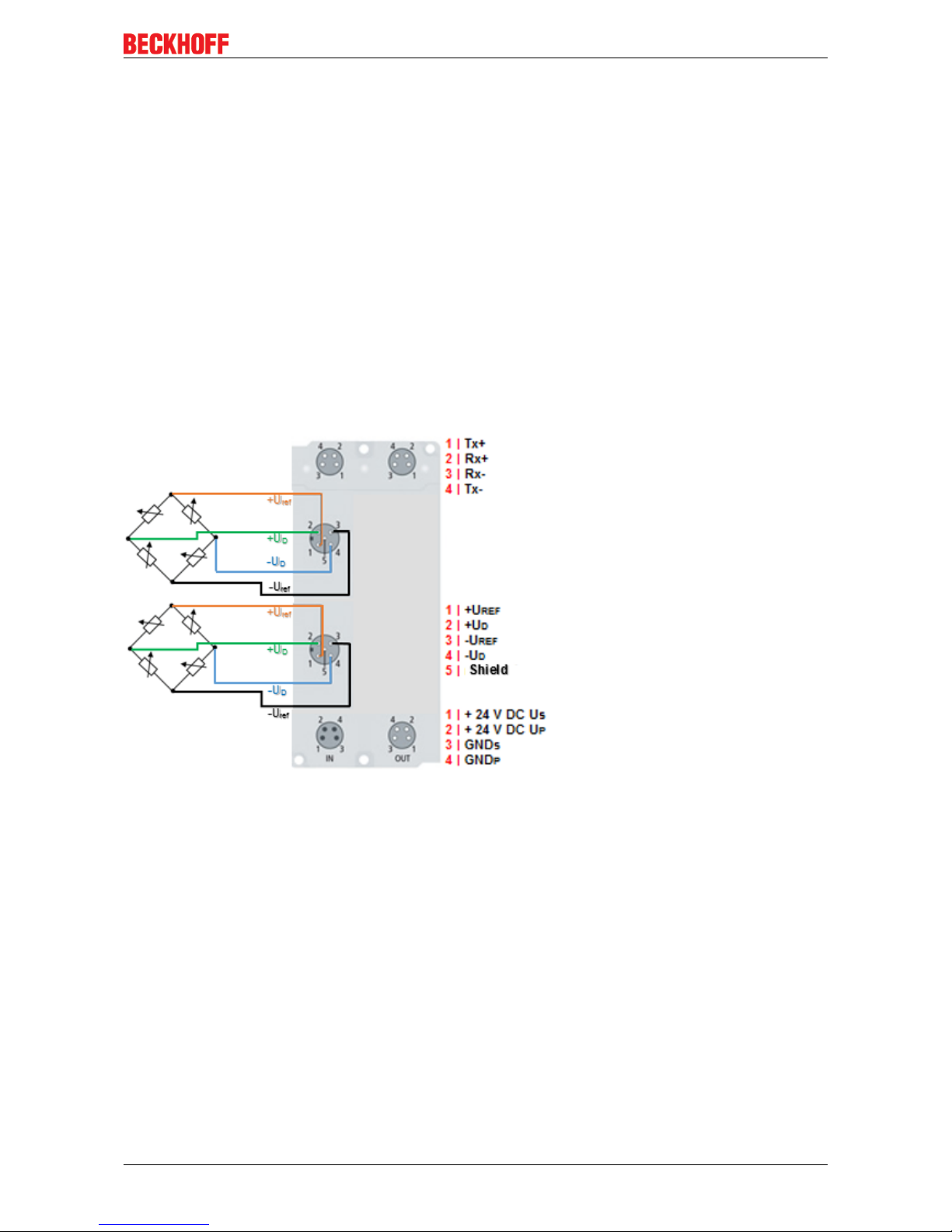
The analog input enables direct connection of a resistor bridge or load cell in a 4-wire connection technology.
Fig.38: Analog volatge input M12, resistor bridge
The shield must be connected to pin 5 of the M12 connector.
You can find an example for the parallel connection of strain gauges here [}15].
The voltage U
ref
is 10 V and is supplied by the EP3356-0022.
Do not earth the cable screen of the sensor on the sensor side
If a shielded sensor cable is used, it should be not grounded on the sensor side. Otherwise it may
come in certain system configurations to error of measurement.
Page 47

EP3356-0022 - Signal connection
EP3356-0022 47Version: 1.1.0
Meanings of the LEDs
Fig.39: LEDs EP3356-0022
LED Color Meaning
RUN green This LED indicates the terminals/boxes operating state:
off
State of the EtherCAT State Machine [}60]: INT = Initialization
of the terminal/box
blinking State of the EtherCAT State Machine: PREOP = Setting for
mailbox communication and variant standard settings
single flash State of the EtherCAT State Machine: SAFEOP = Channel
checking of the Sync Manager [}60] and the Distributed
Clocks: Outputs stay in safe operation mode.
on State of the EtherCAT State Machine: OP = Normal operation
mode, mailbox- and process data communication possible
flickering State of the EtherCAT State Machine: BOOTSTRAP = mode for
firmware updates of the terminal/box
Measure green on Measuring active (valid process data)
off • Calibration active (if LED self calibration is lit) or
• Testing active (if LED self test is lit)
• filters are initialized
Steady state green on The measuring value is steady
off The measuring value is not steady
Self Calibr. green on • Calibration active
• Process data are not valid
Self Test green on • Self test active
• Process data are not valid
Error Dif red on • Channel 1 (strain gauge differential signal) is out of valid
value range
• Internal reference voltage of channel 1 is not present
Error Ref red on • Channel 2 (strain gauge differential signal) is out of valid
value range
• Internal reference voltage of channel 2 is not present
• Reference voltage too low (between -1V and +1V)
Page 48

Commissioning/Configuration
EP3356-002248 Version: 1.1.0
6 Commissioning/Configuration
6.1 TwinCAT configuration setup, manual
This part of the documentation describes the manual configuration of an EtherCAT Box in TwinCAT.
Distinction between Online and Offline
The distinction between online and offline refers to the existence of the actual I/O environment (drives,
terminals). If the configuration is to be prepared in advance of the system configuration as a programming
system, e.g. on a laptop, this is only possible in “Offline configuration” mode. In this case all components
have to be entered manually in the configuration, e.g. based on the electrical design (as described below
under TwinCAT configuration setup, manual). If the designed control system is already connected to the
EtherCAT system and all components are energized and the infrastructure is ready for operation, the
TwinCAT configuration can simply be generated through “scanning” from the runtime system. This is referred
to as online configuration. In any case, during each startup the EtherCAT master checks whether the devices
it finds match the configuration. This test can be parameterized in the advanced device settings.
To ensure that the latest features/settings of the master can be used, always download the latest ESI file.
Please note the following information.
Installation of the latest ESI-XML device description
The TwinCAT System Manager needs the device description files for the devices to be used in order to generate the configuration in online or offline mode. The device descriptions are contained in
the so-called ESI files (EtherCAT Slave Information) in XML format. These files can be requested
from the respective manufacturer and are made available for download. The ESI files for Beckhoff
EtherCAT devices are available on the Beckhoff website (https://www.beckhoff.de/english/down-
load/elconfg.htm?id=1983920606140). The ESI files should be stored in the TwinCAT installation
directory (default: C:\TwinCAT\IO\EtherCAT). The files are read (once) when a new System Manager window is opened. A TwinCAT installation includes the Beckhoff ESI files that were current at
the time when the TwinCAT build was created. From TwinCAT 2.11 and in TwinCAT 3 the ESI directory can be updated from the System Manager, if the programming PC is connected to the internet (TwinCAT → EtherCAT Devices → Update Device Description…)
Page 49

Commissioning/Configuration
EP3356-0022 49Version: 1.1.0
Adding a module manually
• The EtherCAT system must be in a safe, de-energized state before you connect the EtherCAT
modules to the EtherCAT network.
• Switch on the operating voltage, open the TwinCAT System Manager [}59] (Config mode)
• Adding a new I/O device. In the following dialog select the device: EtherCAT (Direct Mode), and
confirm with OK.
Fig.40: Appending a new I/O device (I/O Devices-> right-click -> Append Device...)
Fig.41: Selecting the device (EtherCAT)
• Adding a new Box.
Page 50

Commissioning/Configuration
EP3356-002250 Version: 1.1.0
Fig.42: Appending a new box (Device -> right-click -> Append Box... )
• In the dialog that is displayed select the required Box (e.g. EP6224-2022) and confirm with OK.
Fig.43: Selecting a Box (e.g. EP6224-2022)
Page 51

Commissioning/Configuration
EP3356-0022 51Version: 1.1.0
6.2 Configuration setup: TwinCAT - online scan
This part of the documentation describes the configuration of a physically existing EtherCAT Box in
TwinCAT.
Online configuration setup „Scanning“ (TwinCAT 3.x)
Distinction between Online and Offline
The distinction between online and offline refers to the existence of the actual I/O environment (drives,
terminals). If the configuration is to be prepared in advance of the system configuration as a programming
system, e.g. on a laptop, this is only possible in “Offline configuration” mode. In this case all components
have to be entered manually in the configuration, e.g. based on the electrical design (as described under
TwinCAT configuration setup, manual). If the designed control system is already connected to the EtherCAT
system and all components are energized and the infrastructure is ready for operation, the TwinCAT
configuration can simply be generated through “scanning” from the runtime system. This is referred to as
online configuration. In any case, during each startup the EtherCAT Box checks whether the devices it finds
match the configuration.
To ensure that the latest features/settings of the EtherCAT Box can be used, always download the latest ESI
file. Please note the following information.
Installation of the latest ESI-XML device description
The TwinCAT System Manager needs the device description files for the devices to be used in order to generate the configuration in online or offline mode. The device descriptions are contained in
the so-called ESI files (EtherCAT Slave Information) in XML format. These files can be requested
from the respective manufacturer and are made available for download. The ESI files for Beckhoff
EtherCAT devices are available on the Beckhoff website (https://www.beckhoff.de/english/down-
load/elconfg.htm?id=1983920606140). The ESI files should be stored in the TwinCAT installation
directory (default: C:\TwinCAT\IO\EtherCAT). The files are read (once) when a new System Manager window is opened. A TwinCAT installation includes the Beckhoff ESI files that were current at
the time when the TwinCAT build was created. From TwinCAT 2.11 and in TwinCAT 3 the ESI directory can be updated from the System Manager, if the programming PC is connected to the internet (TwinCAT → EtherCAT Devices → Update Device Description)
The following conditions must be met before a configuration can be set up
Page 52

Commissioning/Configuration
EP3356-002252 Version: 1.1.0
• The actual EtherCAT and IO-Link hardware (devices, couplers, drives) must be present and installed.
• The devices/modules must be connected via an EtherCAT cables or an IO-Link cable in the same way
as they are intended to be used later.
• The devices/modules must be connected to the power supply and ready for communication.
• TwinCAT must be in CONFIG mode on the target system.
The online scan process consists of:
• Detecting the EtherCAT device (Ethernet port at the IPC)
• Detecting the connected EtherCAT devices: This step can be performed independent of the previous
step.
• Troubleshooting
The scan with existing configuration can also be carried out for comparison.
Detecting/scanning of the EtherCAT device
The online device search can be used if the TwinCAT system is in Config mode (blue TwinCAT icon or blue
indication in the System Manager).
Fig.44: TwinCAT Config mode display
Online scanning in Config mode
The online search is not available in RUN mode (production operation).
Note the differentiation between TwinCAT programming system and TwinCAT target system. The
TwinCAT icon next to the Windows clock always shows the TwinCAT mode of the local IPC. The
System Manager window shows the TwinCAT state of the target system.
Right-clicking on "I/O Devices" in the configuration tree opens the search dialog.
Page 53

Commissioning/Configuration
EP3356-0022 53Version: 1.1.0
Fig.45: Scan Devices
This scan mode not only tries to find EtherCAT devices (or Ethernet ports that can be used as such), but
also NOVRAM, fieldbus cards, SMB etc. Not all devices can be found automatically.
Fig.46: Note for automatic device scan
Ethernet ports with installed TwinCAT real-time driver are shown as “RT Ethernet” devices. An EtherCAT
frame is sent to these ports for testing purposes. If the scan agent detects from the response that an
EtherCAT device is connected, the port is immediately shown as an “EtherCAT Device”.
Fig.47: detected Ethernet devices
After confirmation with “OK” a device scan is suggested for all selected devices (see the illustration below).
Page 54

Commissioning/Configuration
EP3356-002254 Version: 1.1.0
Detecting/Scanning the EtherCAT devices
Online scan functionality
During a scan the master queries the identity information of the EtherCAT device from the device
EEPROM. The name and revision are used for determining the type. The respective devices are located in the stored ESI data and integrated in the configuration tree in the default state defined
there.
If an EtherCAT device was created in the configuration (manually or through a scan), the I/O field can be
scanned for devices/slaves.
Fig.48: scan query after automatic creation of an EtherCAT device
The configuration was established and switched directly to the online state (operational). The EtherCAT
system should be in a cyclic operational state, as shown in the following illustration.
Fig.49: online display example
Please note:
• All Boxes should be in OP state
• “frames/sec” should match the cycle time taking into account the sent number of frames
• no excessive “LostFrames” or CRC errors should occur
The configuration is now complete. It can be modified as described under manual procedure.
Page 55

Commissioning/Configuration
EP3356-0022 55Version: 1.1.0
The connected EtherCAT Box (EP6224-3022) is displayed in the TwinCAT tree, as shown in the following
illustration.
Fig.50: Master display after “Scan for boxes”
Troubleshooting
Various effects may occur during scanning.
• An unknown device is detected, i.e. an EtherCAT device for which no ESI XML description is
available.
In this case the System Manager offers to read any ESI that may be stored in the device.
• Device are not detected properly
Possible reasons include
- faulty data links, resulting in data loss during the scan
- the device has an invalid device description
The connections and devices should be checked in a targeted manner, e.g. via the emergency scan.
Then re-run the scan.
Scan over existing Configuration
If a scan is initiated for an existing configuration, the actual I/O environment may match the configuration
exactly or it may differ. This enables the configuration to be compared.
Fig.51: Identical configuration
If differences are detected, they are shown in the correction dialog, so that the user can modify the
configuration as required.
Page 56

Commissioning/Configuration
EP3356-002256 Version: 1.1.0
Fig.52: Example correction dialog
It is recommended to check the „Extended Information“ box, in order to show differences in the revision.
Color Explanation
green This EtherCAT device matches the entry on the other side. Both type and revision match.
blue This EtherCAT device is present on the other side, but in a different revision.
If the found revision is higher than the configured revision, the slave may be used provided
compatibility issues are taken into account.
If the found revision is lower than the configured revision, it is likely that the slave cannot be
used. The found devices may not support all functions that the master expects based on the
higher revision number.
light blue This EtherCAT device is ignored ("Ignore" button)
red This EtherCAT device is not present on the other side.
Device selection based on revision, compatibility
The ESI description also defines the process image, the communication type between master and
device and the device functions, if applicable. The physical device (firmware, if available) has to
support the communication queries/settings of the master. This is backward compatible, i.e. newer
devices (higher revision) should be supported if the EtherCAT master addresses them as an older
revision. The following compatibility rule of thumb is to be assumed for Beckhoff EtherCAT Terminals/Boxes:
Device revision in the system >= device revision in the configuration
This also enables subsequent replacement of devices without changing the configuration (different
specifications are possible for drives). Example: If an EL2521-0025-1018 is specified in the configuration, an EL2521-0025-1019 or higher (-1020, -1021) can be used in practice.
If current ESI descriptions are available in the TwinCAT system, the last revision offered in the selection dialog matches the Beckhoff state of production. It is recommended to use the last device revision when creating a new configuration, if current Beckhoff devices are used in the real application. Older revisions should only be used if older devices from stock are to be used in the application.
Page 57

Commissioning/Configuration
EP3356-0022 57Version: 1.1.0
Fig.53: Example correction dialog with modifications
Once all modifications have been saved or accepted, click “OK” to transfer them to the real *.tsm
configuration.
Page 58

Commissioning/Configuration
EP3356-002258 Version: 1.1.0
6.3 EtherCAT slave process data settings (PDO)
The process data transferred by an EtherCAT slave during each cycle (Process Data Objects, PDOs) are
user data which the application expects to be updated cyclically or which are sent to the slave. To this end
the EtherCAT master (Beckhoff TwinCAT) parameterizes each EtherCAT slave during the start-up phase to
define which process data (size in bits/bytes, source location, transmission type) it wants to transfer to or
from this slave. Incorrect configuration can prevent successful start-up of the slave.
For Beckhoff EtherCAT EL/ES/EP slaves the following applies in general:
• The input/output process data supported by the device are defined by the manufacturer in the ESI/XML
description. The TwinCAT EtherCAT Master uses the ESI description to configure the slave correctly.
• The process data can be modified in the system manager. See the device documentation. Examples of
modifications include: Mask out a channel, displaying additional cyclic information, 16-bit display
instead of 8-bit data size, etc.
• In so-called “intelligent” EtherCAT devices the process data information is also stored in the CoE
directory. Any changes in the CoE directory that lead to different PDO settings prevent successful
startup of the slave. It is not advisable to deviate from the designated process data, because the
device firmware (if available) is adapted to these PDO combinations.
If the device documentation envisages modification of process data, proceed as follows (see illustration
below).
• A: Select the device to configure
• B: In the “Process Data” tab select Input or Output under SyncManager (C)
• D: The PDOs can be selected or deselected
• H: The new process data are visible as linkable variables in the system manager. The new process
data are active once the configuration has been activated and TwinCAT has been restarted (or the
EtherCAT master has been restarted)
• E: If a slave supports this, Input and Output PDO can be modified simultaneously by selecting a socalled PDO record (“predefined PDO settings”).
Fig.54: Configuring the process data
Page 59

Commissioning/Configuration
EP3356-0022 59Version: 1.1.0
Manual modification of the process data
According to the ESI description, a PDO can be identified as "fixed" with a flag "F" in the PDO overview (see previous illustration, J). The configuration of such PDOs cannot be changed, even if TwinCAT offers the associated dialog (“Edit”). In particular, CoE content cannot be displayed as cyclic
process data. This generally also applies in cases where a device supports download of the PDO
configuration, “G”. In case of incorrect configuration the EtherCAT slave usually refuses to start and
change to OP state. The System Manager displays an “invalid SM cfg” logger message:
`Box 1 (EP3356)` (0022): state change aborted (requested ‚SAFEOP`, back to ‚PREOP`), `Box1
(EP3356)` (0022): `PREOP to SAFEOP`failed! Error: `check device state for SAFEOP`, AL Status
`0x0012`read and 0x0004` expected. AL status code `0x001e – invalid SM IN cfg` This error message „invalid SM IN cfg“ or „invalid SM OUT cfg“ provides an indication of the reason for the failed
start.
6.4 Configuration via TwinCAT
In the left-hand window of the TwinCAT System Manager, click on the branch of the EtherCAT Box you wish
to configure (EP2816-0008 in this example).
Fig.55: Branch of the EtherCAT box to be configured
In the right-hand window of the TwinCAT System manager, various tabs are now available for configuring
the EtherCAT Box.
General tab
Fig.56: General tab
Page 60

Commissioning/Configuration
EP3356-002260 Version: 1.1.0
Name Name of the EtherCAT device
Id Number of the EtherCAT device
Type EtherCAT device type
Comment Here you can add a comment (e.g. regarding the system).
Disabled Here you can deactivate the EtherCAT device.
Create symbols Access to this EtherCAT slave via ADS is only available if this checkbox is
activated.
EtherCAT tab
Fig.57: EtherCAT tab
Type EtherCAT device type
Product/Revision Product and revision number of the EtherCAT device
Auto Inc Addr. Auto increment address of the EtherCAT device. The auto increment address can
be used for addressing each EtherCAT device in the communication ring through
its physical position. Auto increment addressing is used during the start-up phase
when the EtherCAT master allocates addresses to the EtherCAT devices. With
auto increment addressing the first EtherCAT slave in the ring has the address
0000
hex
. For each further slave the address is decremented by 1 (FFFF
hex
, FFFE
hex
etc.).
EtherCAT Addr. Fixed address of an EtherCAT slave. This address is allocated by the EtherCAT
master during the start-up phase. Tick the checkbox to the left of the input field in
order to modify the default value.
Previous Port Name and port of the EtherCAT device to which this device is connected. If it is
possible to connect this device with another one without changing the order of the
EtherCAT devices in the communication ring, then this combobox is activated and
the EtherCAT device to which this device is to be connected can be selected.
Advanced Settings This button opens the dialogs for advanced settings.
The link at the bottom of the tab points to the product page for this EtherCAT device on the web.
Process Data tab
Indicates the configuration of the process data. The input and output data of the EtherCAT slave are
represented as CANopen process data objects (PDO). The user can select a PDO via PDO assignment and
modify the content of the individual PDO via this dialog, if the EtherCAT slave supports this function.
Page 61

Commissioning/Configuration
EP3356-0022 61Version: 1.1.0
Fig.58: Process Data tab
Sync Manager
Lists the configuration of the Sync Manager (SM).
If the EtherCAT device has a mailbox, SM0 is used for the mailbox output (MbxOut) and SM1 for the mailbox
input (MbxIn).
SM2 is used for the output process data (outputs) and SM3 (inputs) for the input process data.
If an input is selected, the corresponding PDO assignment is displayed in the PDO Assignment list below.
PDO Assignment
PDO assignment of the selected Sync Manager. All PDOs defined for this Sync Manager type are listed
here:
• If the output Sync Manager (outputs) is selected in the Sync Manager list, all RxPDOs are displayed.
• If the input Sync Manager (inputs) is selected in the Sync Manager list, all TxPDOs are displayed.
The selected entries are the PDOs involved in the process data transfer. In the tree diagram of the System
Manager these PDOs are displayed as variables of the EtherCAT device. The name of the variable is
identical to the Name parameter of the PDO, as displayed in the PDO list. If an entry in the PDO assignment
list is deactivated (not selected and greyed out), this indicates that the input is excluded from the PDO
assignment. In order to be able do select a greyed out PDO, the currently selected PDO has to be
deselected first.
Page 62

Commissioning/Configuration
EP3356-002262 Version: 1.1.0
Activation of PDO assignment
• the EtherCAT slave has to run through the PS status transition cycle (from pre-operational to
safe-operational) once (see Online tab [}65]),
• and the System Manager has to reload the EtherCAT slaves ( button)
PDO list
List of all PDOs supported by this EtherCAT device. The content of the selected PDOs is displayed in the
PDO Content list. The PDO configuration can be modified by double-clicking on an entry.
Column Description
Index PDO index.
Size Size of the PDO in bytes.
Name Name of the PDO.
If this PDO is assigned to a Sync Manager, it appears as a variable of the slave with this
parameter as the name.
Flags F Fixed content: The content of this PDO is fixed and cannot be changed by the System
Manager.
M Mandatory PDO. This PDO is mandatory and must therefore be assigned to a Sync Manager!
Consequently, this PDO cannot be deleted from the PDO Assignment list
SM Sync Manager to which this PDO is assigned. If this entry is empty, this PDO does not take part in
the process data traffic.
SU Sync unit to which this PDO is assigned.
PDO Content
Indicates the content of the PDO. If flag F (fixed content) of the PDO is not set the content can be modified.
Download
If the device is intelligent and has a mailbox, the configuration of the PDO and the PDO assignments can be
downloaded to the device. This is an optional feature that is not supported by all EtherCAT slaves.
PDO Assignment
If this check box is selected, the PDO assignment that is configured in the PDO Assignment list is
downloaded to the device on startup. The required commands to be sent to the device can be viewed in the
Startup [}62] tab.
PDO Configuration
If this check box is selected, the configuration of the respective PDOs (as shown in the PDO list and the
PDO Content display) is downloaded to the EtherCAT slave.
Startup tab
The Startup tab is displayed if the EtherCAT slave has a mailbox and supports the CANopen over EtherCAT
(CoE) or Servo drive over EtherCAT protocol. This tab indicates which download requests are sent to the
mailbox during startup. It is also possible to add new mailbox requests to the list display. The download
requests are sent to the slave in the same order as they are shown in the list.
Page 63

Commissioning/Configuration
EP3356-0022 63Version: 1.1.0
Fig.59: Startup tab
Column Description
Transition Transition to which the request is sent. This can either be
• the transition from pre-operational to safe-operational (PS), or
• the transition from safe-operational to operational (SO).
If the transition is enclosed in "<>" (e.g. <PS>), the mailbox request is fixed and cannot be
modified or deleted by the user.
Protocol Type of mailbox protocol
Index Index of the object
Data Date on which this object is to be downloaded.
Comment Description of the request to be sent to the mailbox
Move Up This button moves the selected request up by one position in the list.
Move Down This button moves the selected request down by one position in the list.
New This button adds a new mailbox download request to be sent during startup.
Delete This button deletes the selected entry.
Edit This button edits an existing request.
CoE - Online tab
The additional CoE - Online tab is displayed if the EtherCAT slave supports the CANopen over EtherCAT
(CoE) protocol. This dialog lists the content of the object directory of the slave (SDO upload) and enables the
user to modify the content of an object from this list. Details for the objects of the individual EtherCAT
devices can be found in the device-specific object descriptions.
Page 64

Commissioning/Configuration
EP3356-002264 Version: 1.1.0
Fig.60: CoE - Online tab
Object list display
Column Description
Index Index and subindex of the object
Name Name of the object
Flags RW The object can be read, and data can be written to the object (read/write)
RO The object can be read, but no data can be written to the object (read only)
P An additional P identifies the object as a process data object.
Value Value of the object
Update List The Update list button updates all objects in the displayed list
Auto Update If this check box is selected, the content of the objects is updated automatically.
Advanced The Advanced button opens the Advanced Settings dialog. Here you can specify which
objects are displayed in the list.
Page 65

Commissioning/Configuration
EP3356-0022 65Version: 1.1.0
Fig.61: Advanced settings
Online
- via SDO information
If this option button is selected, the list of the objects included in the object
directory of the slave is uploaded from the slave via SDO information. The list
below can be used to specify which object types are to be uploaded.
Offline
- via EDS file
If this option button is selected, the list of the objects included in the object
directory is read from an EDS file provided by the user.
Online tab
Fig.62: Online tab
Page 66

Commissioning/Configuration
EP3356-002266 Version: 1.1.0
State Machine
Init This button attempts to set the EtherCAT device to the Init state.
Pre-Op This button attempts to set the EtherCAT device to the pre-operational state.
Op This button attempts to set the EtherCAT device to the operational state.
Bootstrap This button attempts to set the EtherCAT device to the Bootstrap state.
Safe-Op This button attempts to set the EtherCAT device to the safe-operational state.
Clear Error This button attempts to delete the fault display. If an EtherCAT slave fails during
change of state it sets an error flag.
Example: An EtherCAT slave is in PREOP state (pre-operational). The master now
requests the SAFEOP state (safe-operational). If the slave fails during change of
state it sets the error flag. The current state is now displayed as ERR PREOP. When
the Clear Error button is pressed the error flag is cleared, and the current state is
displayed as PREOP again.
Current State Indicates the current state of the EtherCAT device.
Requested State Indicates the state requested for the EtherCAT device.
DLL Status
Indicates the DLL status (data link layer status) of the individual ports of the EtherCAT slave. The DLL status
can have four different states:
Status Description
No Carrier / Open No carrier signal is available at the port, but the port is open.
No Carrier / Closed No carrier signal is available at the port, and the port is closed.
Carrier / Open A carrier signal is available at the port, and the port is open.
Carrier / Closed A carrier signal is available at the port, but the port is closed.
File Access over EtherCAT
Download With this button a file can be written to the EtherCAT device.
Upload With this button a file can be read from the EtherCAT device.
Page 67

Commissioning/Configuration
EP3356-0022 67Version: 1.1.0
6.5 Basic function principles
EL/EP3356 and special versions
Unless stated otherwise, the designation „EL/EP3356“always refers also to special versions such as
the EL3356-0010 and EP3356-0022.
The measuring functions of the EL/EP3356 can be described as follows:
• The EL3356 Analog Input Terminal and the EP3356-0022 Analog Input Box are used to acquire the
supply voltage to a load cell as a reference voltage, and the differential voltage that is proportional to
the force acting on the cell.
• It is compulsory to connect a full bridge. If there is only a quarter or half bridge available, you have to
add external auxiliary bridges. In this case you have to modify the nominal characteristic value.
• The reference and differential voltages are measured simultaneously
• Since the two voltages are measured at the same time, there is basically no need for a high-precision
reference voltage with respect to the level. On changing the reference voltage, the differential voltage
across the full bridge changes by the same degree. Therefore a stabilized reference voltage should be
used that is subject to only low fluctuations (e.g. the EL95xx supply terminal)
• The change of the quotient of the differential and reference voltages corresponds to the relative force
acting on the load cell.
• The quotient is converted into a weight and is output as process data.
• The data processing is subject to the following filtering procedures:
◦ the analog converter (ADC) integrates over 76 samples
◦ calculation of mean values in the averager (if activated)
◦ software filter IIR/FIR (if activated)
• The EL/EP3356 has an automatic compensation/self-calibration function. Default state: self-calibration
activated, execution every 3 minutes
◦ errors in the analog input stages (temperature drift, long-term drift etc.) are checked by regular
automatic calibration, and compensated to bring the measurement within the permitted tolerance
range.
◦ the automatic function can be deactivated or activated in a controlled manner
• The EL/EP3356 can also be used as a 2-channel analog input terminal/box for voltage measurement
[}89].
• The EL3356-0010/EP3356-0022 has a timestamp function that can be activated through Distributed
Clocks. The filter functionality is not available in Distributed Clocks mode.
General notes
• The measuring ranges of both channels (supply voltage and bridge voltage) should always be used as
widely as possible in order to achieve a high measuring accuracy. We recommended a supply voltage
of 12V in connection with a load cell that has such a sensitivity (e.g. 2mV/V) that the largest possible
bridge voltage – ideally ±25mV – is generated. Please consider the max. input voltage (see technical
data).
Page 68

Commissioning/Configuration
EP3356-002268 Version: 1.1.0
Fig.63: Max. input voltages
• Parallel operation of load cells is possible with the EL/EP3356. Please note:
◦ the EL3356 does not provide a supply! Hence, the power supply employed must be sufficiently
large, since the total bridge resistance of all strain gauges connected together is considerably
reduced due to the parallel connection.
◦ Load cells approved and calibrated by the load cell manufacturer for parallel operation should be
used. The nominal characteristic values [mV/V], zero offset [mV/V] and impedance [Ω, ohm] are
then usually adjusted accordingly.
◦ a 6-wire connection is expressly recommended with the EL3356
Fig.64: Parallel connection with EL3356
Page 69

Commissioning/Configuration
EP3356-0022 69Version: 1.1.0
Fig.65: Parallel connection with EP3356
• Load cell signals have a low amplitude and are occasionally very sensitive to electromagnetic
interference. Considering the typical system characteristics and taking into account the technical
possibilities, purposeful state-of-the-art EMC protective measures are to be taken. The shield of the
sensor cable can be connected to the EL3356 at the terminal points 4/8. In the case of high
electromagnetic interference levels, it may be helpful to additionally connect the cable screen before
the terminal using suitable screening material.
• the minimum permissible assigned EtherCAT cycle time for the EL/EP3356 is 100µs.
• If the EL3356-0010/EP3356-0022 is to be used in Distributed Clocks mode:
◦ DC must be activated
◦ the Process data [}92] Timestamp must be activated. The filter functionality is not available then.
Signal flow diagram
Fig.66: Block diagram of EP3356-0022
The EL/EP3356 processes the data in the following order:
• Hardware low-pass 10KHz
• 2-channel simultaneous sampling at 10.5/105.5kSps with 64-fold oversampling by delta-sigma (ΔΣ)
converter and internal pre-filtration
• 4-fold averager (can be deactivated)
• Software filter (can be deactivated)
• Calculating the weight
Page 70

Commissioning/Configuration
EP3356-002270 Version: 1.1.0
Measurement principle of delta-sigma (ΔΣ) converter
The measurement principle employed in the EL/EP3356, with real sampling in MHz range, shifts
aliasing effects into a very high frequency range, so that normally no such effects are to be expected in the KHz range.
Averager
In order to make use of the high data rates of the Analog-to-Digital converter (ADC) even with slow cycle
times, a mean value filter is connected after the ADC. This determines the sliding mean value of the last 4
measured values. This function can be deactivated for each mode via the CoE object "Mode X enable
averager".
Software filter
The EL/EP3356 is equipped with a digital software filter which, depending on its settings, can adopt the
characteristics of a Finite Impulse Response filter (FIR filter), or an Infinite Impulse Response filter (IIR filter).
The filter is activated by default as 50Hz-FIR.
In the respective measuring mode the filter can be activated (0x8000:01, 0x8000:02) [}104] and
parameterized (0x8000:11, 0x8000:12) [}104] (the EL3356-0000 supports only mode 0).
FIR 50/60 Hz
• The filter performs a notch filter function and determines the conversion time of the terminal/box. The
higher the filter frequency, the faster the conversion time. A 50Hz and a 60Hz filter are available.
Notch filter means that the filter has zeros (notches) in the frequency response at the filter frequency
and multiples thereof, i.e. it attenuates the amplitude at these frequencies. The FIR filter operates as a
non-recursive filter.
PDO filter
• The filter behaves like the 50/60Hz FIR filter described above. However, the filter frequency can be
adjusted here in 0.1Hz steps by means of an output data object. The filter frequency range extends
from 0.1Hz to 200Hz and can be reparameterised during operation. To do this the PDO 0x1601
(“RMB filter frequency”) must be displayed in the process data and the entry “PDO filter frequency”
must be selected in the object 0x8000:11. This function allows the EL/EP3356 to suppress interference
of a known frequency in the measuring signal. A typical application, for example, is a silo that is filled
and weighed by a driven screw conveyor. The rotary speed of the screw conveyor is known and can be
adopted into the object as a frequency. Thus mechanical oscillations can be removed from the
measuring signal.
Fig.67: Notch characteristic/amplitude curve and step response of the FIR filter
IIR-Filter 1 to 8
• The filter with IIR characteristics is a discrete time, linear, time invariant filter that can be set to eight
levels (level 1 = weak recursive filter, up to level 8 = strong recursive filter). The IIR can be understood
to be a moving average value calculation after a low-pass filter.
Page 71

Commissioning/Configuration
EP3356-0022 71Version: 1.1.0
Fig.68: Step response and Bode diagramm of the IIR filter
Page 72

Commissioning/Configuration
EP3356-002272 Version: 1.1.0
Overview of conversion times
Filter Settings
Value PDO update
time EL3356
PDO update
time
EP3356-0022/
EL3356-0010
Filter property Limit fre-
quency (-3dB)
[Hz] (typ.)
Comment Rise time
10-90% [s] (typ.)
Filter deactivated
- min. 10ms Cycle-synchronous,, min.
100µs
- - - -
0 FIR 50Hz min. 10ms 312.5 µs 50Hz notch fil-
ter
22Hz Typ. conversion
time 312.5µs
0.013
1 FIR 60Hz min. 10ms 260.4 µs 60Hz notch fil-
ter
25Hz Typ. conversion
time 260.4µs
0.016
2 IIR1 Cyclesyn-
chronous (up to
min. 10ms update)
Cycle-synchronous (up to min.
100 µs)
Low-pass 2000Hz a0=1/21=0.5 0.0003
3 IIR2 Low-pass 500Hz a0=1/22=0.25 0.0008
4 IIR3 Low-pass 125Hz a0=1/24=62.5e-30.0035
5 IIR4 Low-pass 30Hz a0=1/26=15.6e-30.014
6 IIR5 Low-pass 8Hz a0=1/28=3.91e-30.056
7 IIR6 Low-pass 2Hz a0=1/210=977e-60.225
8 IIR7 Low-pass 0.5Hz a0=1/212=244e-60.9
9 IIR8 Low-pass 0.1Hz a0=1/214=61.0e-63.6
10 Dynamic IIR The filter changes dynamically between the filters IIR1 to IIR8
11 PDO Filter fre-
quency
min. 10ms 1/PDO
Value[Hz]*64
Notch filter with
adjustable fre-
quency
ca. 0,443 * PDO
Value [Hz]
- -
Filter and cycle time
If the FIR filters (50Hz or 60Hz) are switched on, the process data are updated maximally with the
specified conversion time (see table). The IIR filter works cycle-synchronously. Hence, a new measured value is available in each PLC cycle.
At which point the filters can be adjusted is described in the chapter “Object description and
parameterization” for example under index 0x8000:12.
IIR filter
Differential equation: Yn = Xn * a0 + Y
n-1
* b1 with a0 + b1 = 1
a0 = (see table), b1 = 1 - a
0
Dynamic IIR Filter
The dynamic IIR filter automatically switches through the 8 different IIR filters depending on the weight
change. The idea:
• The target state is always the IIR8-Filter, i.e. the greatest possible damping and hence a very calm
measured value.
• In the input variable changes rapidly the filter is opened, i.e. switched to the next lower filter (if still
possible). This gives the signal edge more weight and the measured value curve can follow the load
quickly.
• If the measured value changes very little the filter is closed, i.e. switched to the next higher filter (if still
possible). Hence the static state is mapped with a high accuracy.
• The evaluation as to whether a downward change of filter is required or whether an upward change is
possible takes place continuously at fixed time intervals.
Parameterization takes place via the CoE entries 0x8000:13 and 0x8000:14 [}104]. Evaluation takes place
according to 2 parameters:
Page 73

Commissioning/Configuration
EP3356-0022 73Version: 1.1.0
• The "Dynamic filter change time" object (0x8000:13) [}104] is used to set the time interval at which the
existing signal is re-evaluated.
• Object 0x8000:14 [}104] is used to specify the maximum deviation that is permissible during this time
without filter switching occurring.
Example:
The dynamic filter is to be adjusted in such a manner that a maximum slope of 0.5digits per 100ms (5digits
per second) is possible without the filter being opened. This results in a "calm" measured value. In the case
of a faster change, however, it should be possible to immediately follow the load.
• Dynamic filter change time (0x8000:13) [}104] = 10 (equivalent to 100ms)
• Object 0x8000:14 [}104] is used to specify the maximum deviation that is permissible during this time
without filter switching occurring.
The measured value curve is shown below for a slower (left) and faster (right) change.
Fig.69: Effect of dynamic IIR filters
• Left: The scales are slowly loaded. The change in the weight (delta/time) remains below the mark of
0.5digits per 100ms. The filter therefore remains unchanged at the strongest level (IIR8), resulting in a
low-fluctuation measured value.
• Right: The scales are suddenly loaded. The change in the weight immediately exceeds the limit value
of 0.5digits per 100ms. The filter is opened every 100ms by one level (IIR8 --> IIR7 --> IIR6 etc.) and
the display value immediately follows the jump. After the removal of the weight the signal quickly falls
again. If the change in the weight is less than 0.5digit per 100ms, the filter is set one level stronger
every 100ms until IIR8 is reached. The green line is intended to clarify the decreasing "noise level"
Calculating the weight
Each measurement of the analog inputs is followed by the calculation of the resulting weight or the resulting
force, which is made up of the ratio of the measuring signal to the reference signal and of several
calibrations.
YR = (U
Diff
/ U
ref
) x A
i
(1.0) Calculation of the raw value in mV/V
YL = ( (YR – CZB) / (Cn – CZB) ) * E
max
(1.1) Calculation of the weight
YS = YL * A
S
(1.2) Scaling factor (e.g. factor 1000 for rescaling from
kg to g)
YG = YS * (G / 9.80665) (1.3) Influence of acceleration of gravity
Y
AUS
= YG x Gain - Tara (1.4) Gain and Tare
Page 74

Commissioning/Configuration
EP3356-002274 Version: 1.1.0
Legend
Name Designation CoE Index
U
Diff
Bridge voltage/differential voltage of the sensor element, after averager
and filter
U
ref
Bridge supply voltage/reference signal of the sensor element, after
averager and filter
A
i
Internal gain, not changeable. This factor accounts fort he unit
standardisation from mV to V and the different full-scale deflections of the
input channels
C
n
Nominal characteristic value of the sensor element (unit mV/V, e.g.
nominally 2mV/V or 2.0234mV/V according to calibration protocol)
8000:23 [}104]
C
ZB
Zero balance of the sensor element (unit mV/V, e.g. -0.0142 according to
calibration protocol)
8000:25 [}104]
E
max
Nominal load of the sensor element
8000:24 [}104]
A
S
Scaling factor (e.g. factor 1000 for rescaling from kg to g)
8000:27 [}104]
G Acceleration of gravity in m/s^2 (default: 9.80665ms/s^2)
8000:26 [}104]
Gain
8000:21 [}104]
Tare
8000:22 [}104]
Conversion mode
The so–called conversion mode determines the speed and latency of the analog measurement in the EL/
EP3356. The characteristics:
Mode Meaning typ. la-
tency
EL3356 EL3356-0010
and
EP3356-0022
typ. current
consumption
0 High precision
Analog conversion at 10.5kSps
(samples per second) Slow conversion
and thus high accuracy
7,2ms x x 70%
(see Technical
data [}9] re-
garding nomi-
nal value)
1 High speed / low latency Analog
conversion at 105.5kSps (samples per
second) Fast conversion with low latency
0,72ms - x 100%
(see Technical
data [}9] re-
garding nomi-
nal value)
Due to the conversion principle of the EL/EP3356, the analog voltage is only available as a digital value after
a defined time. This is shown in figure below.
A step signal 0->1 is applied to the input. The measured value is reached and readable within the defined
accuracy after 7.2ms or 0.72ms, depending on the conversion mode 0/1. At this time the timestamp is also
acquired in Distributed Clocks mode. In real operation a step signal is not normally connected, but rather a
higher frequency but constant signal. The EL3356 then maps the input signal with the corresponding latency
for further processing, for which reason faster querying of the sampling unit at shorter intervals than the
latency (EL3356-0010 allows up to 100µs) makes sense for true-to-detail mapping of the analog input
signal.
Page 75

Commissioning/Configuration
EP3356-0022 75Version: 1.1.0
Fig.70: Latency of the Analog-to-Digital converter
It is not possible to change the specified latency.
Beyond that the following are individually adjustable in each mode via CoE
• activation of the averager
• activation of the filter
• type of filter
Fig.71: Setting parameters in CoE belonging to the individual modes
The EL3356 has only mode 0, the El3356-0010 has modes 0 & 1.
Page 76

Commissioning/Configuration
EP3356-002276 Version: 1.1.0
Mode change (EL3356-0010 only)
In particular for dynamic weighing procedures it may make sense to considerably change the measuring
characteristic during the weighing procedure. For example, if a bulk material is filled by the sack within
5seconds, a very open filter should initially be used so that the measured value quickly follows the fill level.
During this phase it is of no importance that the measured value is very inaccurate and subject to high
fluctuations. If the sack is >90% full, filling must be slowed down and the loading must be followed with
higher accuracy; the filter must be closed. Therefore the two conversion modes can be switched via the
process data bit "Sample mode" in the EL3356-0010 and in the EP3356-0022 in relation to the processing of
the analog values.
The mode change takes about 30ms, during which time the measured values are invalid and indicate this by
the status byte.
Fig.72: Sample mode switching
Page 77

Commissioning/Configuration
EP3356-0022 77Version: 1.1.0
6.6 Application notes
Symmetric reference potential
The EL/EP3356 measures the two voltages U
supply
und U
bridge
independently of each other and without
electrical reference to a supply voltage. The measuring accuracy can be increased still further if an internal
coupling is employed to prevent the internal measuring circuits from drifting apart. To this end the EL/
EP3356 has an internal switch that is closed in the default state and establishes a potential reference
between the internal electronics and the bridge point.
Fig.73: Internal switch for increasing the measuring accuracy
If several strain gauges are supplied by the same power supply and equalising currents flow that falsify the
measurement, the switch can be opened via CoE 0x8000:05 [}104]. Alternatively, electrically isolated strain
gauge supplies are to be installed.
Open-circuit recognition
The EL/EP3356 has no express open-circuit recognition facility. If one of the bridge wires is broken,
however, the voltage measured there generally moves towards the final value, thus displaying an error in the
status word. Over/underrange of the supply voltage is likewise indicated.
Input freeze
If the terminal/box is placed in the freeze state by InputFreeze in the control word, no further analog
measured values are relayed to the internal filter. This function is usable, for example, if a filling surge is
expected from the application that would unnecessarily overdrive the filters due to the force load. This would
result in a certain amount of time elapsing until the filter had settled again. The user himself must determine
a sensible InputFreeze time for his filling procedure.
For clarification: temporal control of the InputFreeze and the decision regarding its use must be realised by
the user in the PLC, they are not components of the EL/EP3356.
In the following example (recorded with Scope2) impulses on a 15kg load cell are recorded; the filter is wide
open at IIR1 so that steep edges occur in the signal.
Page 78

Commissioning/Configuration
EP3356-002278 Version: 1.1.0
Fig.74: Impulses on a load cell with and without InputFreeze
Explanation: The weight (A) is shown in blue; the state of the InputFreeze variable, which can be controlled
by the PLC program and can be TRUE/FALSE, is shown in red (B). The first two impulses (C) lead to large
peak deflections in the signal. After that the following is activated in the PLC program (see example program
[}113]):
• if the measured value for the last cycle (cycle time 100µs) has changed by more than 10g (indicating
a sudden load), bInputFreeze is set to TRUE for 50ms by a TOF block on the EL/EP3356
The effect can be seen in (D): The peak load is no longer acknowledged by the EL/EP3356. If it is optimally
adapted to the expected force impulse, the EL/EP3356 can measure the current load value without
overshoot.
Gravity adaption
The calculation of the weight depends on the gravitation/the Earth's gravitational force/acceleration due to
gravity at the place of installation of the scales. In general, acceleration due to the gravitational pull of the
earth at the place of installation is not equal to the defined standard value of g = 9.80665m/s². For example,
4 zones of acceleration due to gravity are defined in Germany, in which a local acceleration due to gravity of
9.807m/s² to 9.813m/s² is to be assumed. Hence, within Germany alone there is a clear dispersion of the
order of parts per thousand for acceleration due to gravity, which has a direct effect on the measured weight
in accordance with the equation FG=m*g!
If
• load cells are used in the theoretical calibration with characteristic values according to the sensor
certificate
• calibration weights are used whose weight at the place of installation of the scales is by nature different
to that at the place of origin
• scales of the accuracy class I to III are to be realized
• scales that are generally independent of acceleration due to gravity are to be realized
then one should check whether the gravity correction needs to be adapted via object 0x8000:26 [}104].
Page 79

Commissioning/Configuration
EP3356-0022 79Version: 1.1.0
Idling recognition
Weighing is a dynamic procedure that can lead to large jumps in the bridge voltage and thus to the
calculation of the value. Following a change in load, the measured value must first "settle" so that the
process value is evaluable in the controller. The evaluation of the measured value and the decision over the
degree of calmness can be done in the controller; however, the EL/EP3356 also offers this function, which is
activated by default. The result is output in the status word.
• If the load value remains within a range of values y for longer than time x, then the SteadyState is
activated in the StatusWord.
• SteadyState is set to FALSE as soon as this condition no longer applies.
• The parameters x and y can be specified in the CoE
• The evaluation is naturally considerably affected by the filter setting
In the following example (recorded with TwinCAT Scope2), a 15kg load cell is suddenly unloaded and
loaded with 547g. SteadyState is subject to a window time from 100ms and a tolerance of 8g (15kg
nominal value, scaling 1000; see CoE).
Fig.75: Load cell loaded and unloaded
Official calibration capability
"Official calibration" is a special kind of calibration that is accomplished according to special regulations with
the involvement of trained personnel using prescribed aids. The use of "officially calibrated" scales is
mandatory in the Central European region, in particular for the filling of foodstuffs. This ensures the
correctness of the weighed quantities in a particular way.
The Beckhoff EL/KL335x terminals and the EP3356 boxes cannot be officially calibrated as individual
devices. However, they can be integrated as elements in applications that can then be equipped by the
integrator with the required characteristics for official calibration capability using appropriate means.
Page 80

Commissioning/Configuration
EP3356-002280 Version: 1.1.0
6.7 Calibration and adjustment
The term "calibration" can be applied in 3 different ways to the EL/EP3356:
• Sensor calibration: once-only calibration of the employed sensor (strain gauge) during commissioning
of the system
• Self-calibration: continuously repeated self-calibration of the terminal/box for the improvement of the
measuring accuracy
• Tare: repeated gross/net compensation by taring
EL/EP3356 and special versions
Unless stated otherwise, the designation „EL/EP3356“ always refers also to special versions such
as the EL3356-0010 and the EP3356-0022.
Sensor calibration
The EL/EP3356 is matched to the characteristic curve of the sensor element by means of the calibration.
Two values are required for this procedure: the initial value without a load ("zero balance") and fully loaded
("rated output"). These values can be determined by a calibration protocol or by a calibration using
calibration weights.
Fig.76: Adaptation to the sensor curve
Calibration by means of compensation in the system
In the "practical" calibration, measurement takes place first with the scales unloaded, then with a defined
load on the scales. The EL/EP3356 automatically calculates the existing sensor characteristic values from
the measured values.
Sequence:
1. Perform a CoE reset with object 0x1011:01, see Restoring the delivery state [}118]
2. Set scale factor to 1000 (0x8000:27 [}104]) (for declaration of weight in g)
3. Set gravity of earth (0x8000:26 [}104]) if necessary (default: 9.806650)
4. Set gain to (0x8000:21 [}104]) = 1
5. Set tare to 0 (0x8000:22 [}104])
6. Set the filter (0x8000:11 [}104]) to the strongest level: IIR8
7. Specify the nominal load of the sensor in 0x8000:24 [}104] ("Nominal load")
Page 81

Commissioning/Configuration
EP3356-0022 81Version: 1.1.0
8. Zero balance: Do not load the scales. As soon as the measured value indicates a constant value for at
least 10seconds, execute the command "0x0101" (257dec) on CoE object 0xFB00:01 [}102]. This
command causes the current mV/V value (0x9000:11 [}104]) to be entered in the "Zero balance" object. Check: CoE objects 0xFB00:02 [}102] and 0xFB00:03 [}102] must contain "0" after execution
9. Load the scales with a reference load. This should be at least 20% of the rated load. The larger the
reference load, the better the sensor values can be calculated. In object 0x8000:28 [}104] ("Reference
load"), enter the load in the same unit as the rated load (0x8000:24 [}104]). As soon as the measured
value indicates a constant value for at least 10seconds, execute the command "0x0102" (258dec) on
CoE object 0xFB00:01 [}102]. By means of this command the EL/EP3356 determines the output value
for the nominal weight ("Rated output") Check: CoE objects 0xFB00:02 [}102] and 0xFB00:03 [}102]
must contain "0" after execution.
10. Reset: execute the command "0x0000" (0dec) on CoE object 0xFB00:01 [}102].
11. Set the filter to a lower stage.
Calibration according to the sensor calibration protocol (theoretical calibration)
The sensor characteristic values according to the manufacturer's certificate are communicated here directly
to the EL/EP3356, so that it can calculate the load.
1. Perform a CoE reset with object 0x1011:01, see Restoring the delivery state [}118]
2. Set scale factor to 1000 (0x8000:27 [}104]) (for declaration of weight in g)
3. Set gravity of earth (0x8000:26 [}104]) if necessary (default: 9.806650)
4. Set gain to (0x8000:21 [}104]) = 1
5. Set tare to 0 (0x8000:22 [}104])
6. Specify the nominal load of the sensor in 0x8000:24 [}104] ("Nominal load")
7. Adopt the "Rated output" (mV/V value 0x8000:23 [}104]) from the calibration protocol
8. Adopt the "Zero balance" (0x8000:25 [}104]) from the calibration protocol
Calibration
The calibration is of great importance for the accuracy of the system. In order to increase this, the
filter should be set as strong as possible over the entire calibration phase. It may take several seconds before a static value is obtained.
Page 82

Commissioning/Configuration
EP3356-002282 Version: 1.1.0
Local storage
The values modified during the theoretical and practical calibration are stored in a local EEPROM.
This can be written to up to 1 million time. In order to prolong the life of the EEPROM, therefore, the
commands should not be executed cyclically.
Self-calibration of the measuring amplifiers
The measuring amplifiers are periodically subjected to examination and self-calibration. Several analog
switches are provided for this purpose, so that the various calibration signals can be connected. It is
important for this process that the entire signal path, including all passive components, is examined at every
phase of the calibration. Only the interference suppression elements (L/C combination) and the analog
switches themselves cannot be examined. In addition, a self-test is carried out at longer intervals.
The self-calibration is carried out every 3minutes in the default setting.
Self-calibration
• The time interval is set in 100ms steps with object 0x8000:31 [}104]; default: 3min. Duration approx.
150ms
Self-test
• is additional carried out together with every nth self-calibration. The multiple (n) is set with object
0x8000:32 [}104]; default: 10 additional duration approx. 70ms.
By means of the self-calibration of the input stages at the two operating points (zero point and final value),
the two measuring channels are calibrated to each other.
Interface for controller
The self-calibration takes place automatically at the defined intervals. In order to prevent calibration during a
time-critical measurement, the automatic calibration can be disabled via the "Disable calibration" bit in
ControlWord, also permanently. If it should be additional necessary to carry out a manual test, this is started
by a rising edge of the "Start manual calibration" bit in the process image.
While the terminal is performing a self-calibration or a self-test, the "Calibration in progress" bit is set in the
process image. Once started, a self-calibration/self-test cannot be aborted.
If the self-calibration has been disabled by "Disable calibration", it can nevertheless be started by the "Start
calibration" process data bit.
Self-calibration
The self-calibration takes place for the first time directly after starting up the terminal/box. At this
point the external reference voltage must already be applied. If the reference voltage is only applied
later, the self-calibration must be manually initiated (process data bit: „Start calibration“). The selfcalibration must be executed at least once after each start-up. The supply voltage must be applied
during the self-calibration, since otherwise the necessary reference voltages cannot be generated.
A lower measuring accuracy is to be expected if the self-calibration is disabled for a longer period or
permanently.
After a change of the settings in the CoE (range x80nn), a self-calibration will be executed in each case (also
for DisabledCalibration = TRUE), because the settings have an influence to the measuring procedure. CoE
settings should be done as far as possible out of running measuring procedures.
Taring
When taring, the scales are "zeroed" using an arbitrary applied load; i.e. an offset correction is performed.
This is necessary for the gross/net compensation of goods that cannot be weighed without a container that
has a mass of its own.
The EL/EP3356 supports 2 tarings; it is recommended to set a strong filter when taring.
Temporary tare
Page 83

Commissioning/Configuration
EP3356-0022 83Version: 1.1.0
• The correction value is NOT stored in the terminal/box and is lost in the event of a power failure. To
this end the command "0x0001" is executed on CoE object 0xFB00:01 [}102] (binary dialog in the
System Manager: "01 00"). This sets the tare object (0x8000:22 [}104]) such that the display value is
0. Note: in the case of a device restart (INIT → OP) the tare is not deleted. In addition this tare can be
executed via the control word:
Permanent tare
• The correction value is stored locally in the terminal's/boxes EEPROM and is not lost in the event of a
power failure. To this end the command "0x0002" is executed on CoE object 0xFB00:01 [}102] (binary
dialog in the System Manager: "02 00"). This sets the tare object (0x8000:22 [}104]) such that the
display value is 0.
Local storage
The values modified during the theoretical and practical calibration are stored in a local EEPROM.
This can be written to up to 1million time. In order to prolong the life of the EEPROM, therefore, the
commands should not be executed cyclically.
Commands
The functions discussed above are carried out by means of commands in the standardized object 0xFB00
[}102].
Index Name Comment
FB00:01 Request Entry of the command to be executed
FB00:02 Status Status of the command currently being executed
0: Command executed without error
255: Command is being executed
FB00:03 Response Optional response value of the command
The function blocks FB_EcCoESdoWrite and FB_EcCoESdoRead from the TcEtherCAT.lib (contained in the
standard TwinCAT installation) can be used in order to execute the commands from the PLC.
Commands of the EL/EP3356
The following commands can be transferred to the terminal/box via the CoE entry 0xFB00:01 [}102].
Command Comment
0x0101 Execute zero balance
0x0102 Execute calibration
0x0001 Execute tare procedure (value is NOT saved in the terminal's/boxes EEprom)
0x0002 Execute tare procedure (value is saved in the terminal's/boxes EEprom)
Page 84

Commissioning/Configuration
EP3356-002284 Version: 1.1.0
6.8 Notices on analog specifications
Beckhoff I/O devices (terminals, boxes) with analog inputs are characterized by a number of technical
characteristic data; refer to the technical data in the respective documents.
Some explanations are given below for the correct interpretation of these characteristic data.
Full scale value
An I/O device with an analog input measures over a nominal measuring range that is limited by an upper and
a lower limit (initial value and end value); these can usually be taken from the terminal/box designation. The
range between the two limits is called the measuring span and corresponds to the equation (end value initial value). Analogous to pointing devices this is the measuring scale (see IEC61131) or also the dynamic
range. For analog I/O devices from Beckhoff the rule is that the limit with the largest value is chosen as the
full scale value of the respective product (also called the reference value) and is given a positive sign. This
applies to both symmetrical and asymmetrical measuring spans.
Fig.77: Measuring range
For the above examples this means:
• Measuring range 0 to 10V: asymmetric unipolar, full scale value = 10V, measuring span = 10V
• Measuring range 4 to 20mA: asymmetric unipolar, full scale value = 20mA, measuring span = 16mA
• Measuring range -200 to 1370°C: asymmetric bipolar, full scale value = 1370°C, measuring span =
1570°C
• Measuring range -10 to +10V: symmetric bipolar, full scale value = 10V, measuring span = 20V
This applies equally for analog output terminals/boxes.
± Measuring error [% of the full scale value] (also: measurement error)
The relative measuring error is referenced to the full scale value and is calculated as the quotient of the
largest numerical deviation from the true value (‘measuring error’) referenced to the full scale value.
The measuring error is generally valid for the entire permitted operating temperature range, also called the
‘usage error limit’ and contains random and systematic portions of the referred device (i.e. ‘all’ influences
such as temperature, inherent noise, aging, etc.).
It always to be regarded as a positive/negative span with ±, even if it is specified without ± in some cases.
The maximum deviation can also be specified directly.
Page 85

Commissioning/Configuration
EP3356-0022 85Version: 1.1.0
Example: Measuring range 0 to 10V and measuring error <±0.3% full scale value → maximum deviation
±30mV in the permissible operating temperature range.
Notice: since this specification also includes the temperature drift, a significantly lower measuring error can
usually be assumed in case of a constant ambient temperature and thermal stabilization of the device. This
applies equally for analog output terminals/boxes.
Single-ended/differential typification
For analog inputs Beckhoff makes a basic distinction between two types: single-ended (SE) and differential
(DIFF), referring to the difference in electrical connection with regard to the potential difference.
The diagram shows two-channel versions of an SE module and a DIFF module as examples for all multichannel versions.
Fig.78: Single-ended/differential typification
Notice: Dashed lines indicate that the respective connection may not necessarily be present in each SE or
DIFF module.
The basic rule:
• Analog measurements always take the form of voltage measurements between two potential points.
For voltage measurements a large R is used, in order to ensure a high impedance. For current
measurements a small R is used as shunt. If the purpose is resistance measurement, corresponding
considerations are applied.
◦ Beckhoff generally refers to these two points as input+/signal potential and input-/reference
potential.
◦ For measurements between two potential points two potentials have to be supplied.
◦ Regarding the terms "single-wire connection" or "three-wire connection", please note the following
for pure analog measurements: three- or four-wire connections can be used for sensor supply, but
are not involved in the actual analog measurement, which always takes place between two
potentials/wires. In particular this also applies to SE, even though the term suggest that only one
wire is required.
• The term "electrical isolation" should be clarified in advance. Beckhoff IO modules feature 1…8 or
more analog channels; with regard to the channel connection a distinction is made in terms of:
◦ how the channels WITHIN a module relate to each other, or
◦ how the channels of SEVERAL modules relate to each other.
Page 86

Commissioning/Configuration
EP3356-002286 Version: 1.1.0
The property of electrical isolation indicates whether the channels are directly connected to each other.
• Beckhoff terminals/boxes always feature electrical isolation between the field/analog side and the bus/
EtherCAT side. In other words, if two analog terminals/boxes are not connected via the power contacts,
the modules are effectively electrically isolated.
• If channels within a module are electrically isolated, or if a single-channel module has no power
contacts, the channels are effectively always differential. See also explanatory notes below. Differential
channels are not necessarily electrically isolated.
• Analog measuring channels are subject to technical limits, both in terms of the recommended operating
range (continuous operation) and the destruction limit. Please refer to the respective terminal
documentation for further details.
Explanation
• Differential
◦ Differential measurement is the most flexible concept. The user can freely choose both connection
points, input+/signal potential and input-/reference potential, within the framework of the technical
specification.
◦ A differential channel can also be operated as SE, if the reference potential of several sensors is
linked. This interconnection may take place via the system GND.
◦ Since a differential is configured symmetrically internally (see diagram), there will be a mid-
potential (X) between the two supplied potentials that is the same as the internal ground/reference
ground for this channel. If several DIFF channels are used in a module without electrical isolation,
the technical property VCM (common-mode voltage) indicates the degree to which the mean
voltage of the channels may differ.
◦ The internal reference ground may be accessible as connection point at the terminal/box, in order
to stabilize a defined GND potential in the terminal/box. In this case it is particularly important to
pay attention to the quality of this potential (noiselessness, voltage stability). At this GND point a
wire may be connected to make sure that V
CM,max
is not exceeded in the differential sensor cable. If
differential channels are not electrically isolated, usually only one V
CM,max
is permitted. If the
channels are electrically isolated this limit should not apply, and the channels voltages may differ
up to the specified separation limit.
◦ Differential measurement in combination with correct sensor wiring has the special advantage that
any interference affecting the sensor cable (ideally the feed and return line are arranged side by
side, so that interference signals have the same effect on both wires) has very little effect on the
measurement, since the potential of both lines varies jointly (hence the term common mode). In
simple terms: Common-mode interference has the same effect on both wires in terms of amplitude
and phasing.
◦ Nevertheless, the suppression of common-mode interference within a channel or between
channels is subject to technical limits, which are specified in the technical data.
• Single Ended
◦ If the analog circuit is designed as SE, the input/reference wire is internally fixed to a certain
potential that cannot be changed. This potential must be accessible from outside on at least one
point for connecting the reference potential, e.g. via the power contacts.
◦ In other words, in situations with several channels SE offers users the option to avoid returning at
least one of the two sensor cables to the terminal/box (in contrast to DIFF). Instead, the reference
wire can be consolidated at the sensors, e.g. in the system GND.
◦ A disadvantage of this approach is that the separate feed and return line can result in voltage/
current variations, which a SE channel may no longer be able to handle. See common-mode
interference. A VCM effect cannot occur, since the module channels are internally always 'hardwired' through the input/reference potential.
Typification of the 2/3/4-wire connection of current sensors
Current transducers/sensors/field devices (referred to in the following simply as ‘sensor’) with the industrial
0/4-20mA interface typically have internal transformation electronics for the physical measured variable
(temperature, current, etc.) at the current control output. These internal electronics must be supplied with
energy (voltage, current). The type of cable for this supply thus separates the sensors into self-supplied or
externally supplied sensors:
Page 87

Commissioning/Configuration
EP3356-0022 87Version: 1.1.0
• Self-supplied sensors
◦ The sensor draws the energy for its own operation via the sensor/signal cable + and -. So that
enough energy is always available for the sensor’s own operation and open-circuit detection is
possible, a lower limit of 4mA has been specified for the 4-20mA interface; i.e. the sensor allows
a minimum current of 4mA and a maximum current of 20mA to pass.
◦ For a 2-wire connection; see IEC60381-1
◦ Such current transducers generally represent a current sink and thus like to sit between + and – as
a ‘variable load’. Refer also to the sensor manufacturer’s information.
Therefore, they are to be connected according to the Beckhoff terminology as follows:
• preferably to ‘single-ended’ inputs if the +Supply connections of the terminal/box are also to be used connect to +Supply and Signal
• the sensor draws the energy/operating voltage for its own operation from 2 supply cables of its own.
One or two further sensor cables are used for the signal transmission of the current loop:
Externally supplied sensors
• 3- and 4-wire connection see Fig. Connection of externally supplied sensors, cf. IEC60381-1
• the sensor draws the energy/operating voltage for its own operation from 2 supply cables of its
own. One or two further sensor cables are used for the signal transmission of the current loop:
1. sensor cable: according to the Beckhoff terminology such sensors are to be connected to ‘singleended’ inputs in 3 cables with +/-/Signal lines and if necessary FE/shield
2. sensor cables: In the case of sensors with 4-wire connection according to +-/+Signal/-Signal, you must
check whether +Signal may be connected to +Supply or –Signal to –Supply.
◦ Yes: then you can connect accordingly to a Beckhoff ‘single-ended’ input.
◦ the Beckhoff ‘differential’ input for +Signal and –Signal is to be selected; +Supply and –Supply
are to be connected via additional cables.
Notice: expert organizations such as NAMUR demand a usable measuring range <4mA/>20mA for error
detection and adjustment, see also NAMURNE043.
The Beckhoff device documentation must be consulted in order to see whether the respective device
supports such an extended signal range.
In general the polarity/direction of current is to be observed due to the internal diode!
Page 88

Commissioning/Configuration
EP3356-002288 Version: 1.1.0
Fig.79: 2/3/4-wire connection as single-ended or differential connection technology
Page 89

Commissioning/Configuration
EP3356-0022 89Version: 1.1.0
6.9 Voltage measurement
EL/EP3356 and special versions
Unless stated otherwise, the designation „EL/EP3356“ always refers also to special versions such
as the EL3356-0010 and EP3356-0022.
The EL/EP3356 principally offers a 2-channel voltage measurement on one terminal/box with 2 very different
measuring ranges of ±25mV and ±12V nominal voltage. The load on the one connected strain gauge can
be calculated from the two simultaneously measured voltages; the EL/EP3356 already performs this
calculation in the terminal/box and thus represents a 1-channel terminal/box in the sense of load calculation.
The following applies to the individual channels:
• Channel 1:
◦ Typical measuring range approx. -13.5V to 0 to +13.5V (equivalent to process value
0x80.00.00.00 to 0 to 0x7F.FF.FF.FF)
◦ Nominal measuring range: -12V... 0 ... +12V
◦ max. permissible voltage -UD vs. +UD: ±13.5V
◦ Measuring error< ±0.1% of the full scale value, 50Hz filter active
• Channel 2:
◦ Typical measuring range approx. -27mV to 0 to +27mV (equivalent to process value
0x80.00.00.00 to 0 to 0x7F.FF.FF.FF)
◦ Nominal measuring range: -25mV... 0 ... +25mV
◦ max. permissible voltage -U
ref
vs. +U
ref
: ±27mV
◦ Measuring error< ±0.1% of the full scale value, 50Hz filter active
• in strain gauge mode the connected strain gauge guarantees that no impermissibly high potential
differences arise inside and outside the circuit.
In the standard setting the EL/EP3356 operates as a 1-channel strain gauge monitor with the process image
[}92]; the terminal/box can be switched to 2-channel voltage measurement by changing the process data.
See the notes on the process image regarding this. If the EL/EP3356 is not used as a load measuring
terminal/box, but rather as a 2-channel analog input measuring terminal/box, the following must be observed:
• The CoE settings are to be found for:
◦ Channel 1: objects under 0x8010:xx [}102]
◦ Channel 2: objects under 0x8020:xx [}102]
◦ the strain gauge objects under x8000:xx have no function. Exception: the averager (0x8000:03
[}104]) can also be used in voltage measuring mode and applies to both channels
simultaneously.
• Self-calibration is not possible and useful.
• The two analog channels are not calibrated by the manufacturer, since this is not required for the
relative measurement in strain gauge mode. This means, for example, for channel 1 with a nominal
measuring range of ±12V or a typical measuring range of ±13.5V, that the maximum measured value
0x7F.FF.FF.FF can be output by one terminal/box for example as 13.4V and by another as 13.6V. If
terminals/boxes output identical process values for identical applied voltages, meaning that they are
exchangeable, each channel must be calibrated by the user by making settings for each channel in the
CoE. The user calibration (CoE 0x80n0:17 [}102] [offset], 0x80n0:18 [}102] [gain]) or the user scaling
(CoE 0x80n0:11 [}102] [offset], 0x80n0:12 [}102] [gain]) can be used for this.
Page 90

Commissioning/Configuration
EP3356-002290 Version: 1.1.0
Voltage measurement
In the voltage measuring mode the EL3356 is to be connected to external GND with a single-ended
connection. In addition the internal GND reference is to be closed by the CoE switch SymmetricRef-
erencePotential. The EP3356 “supply” is not usable because the box internally generated 10V.
Page 91

Commissioning/Configuration
EP3356-0022 91Version: 1.1.0
6.10 Distributed Clocks mode (EL3356-0010 and
EP3356-0022 only)
In the Distributed Clocks mode (DC mode), the precise timestamp is recorded for each measured value and
transmitted to the controller as cyclic process data. To this end
• DC must be activated. To do this, select DC-Synchron (input based) on the "DC" tab
• The PDO x1A03 in the Process data management [}92] is to be activated in the SyncManager 3
"Inputs"
Fig.80: Activation of DC and PDO timestamp in the TwinCAT System Manager
The EL3356-0010/EP3356-0022 operates free running with a cyclic, but not equidistant measurement; the
time intervals between 2 measured values are therefore not constant. For this reason the 64-bit timestamp
delivered with the process value must be evaluated by the user.
In order to suppress falsification of the measurement results by upstream filters, both the software filter and
the averager are deactivated in this operating mode. The measurement/calculation and provision of the
measured value in the process data therefore takes place at the conversion rate corresponding to the mode:
• EL3356: 10.5kSps
• EL3356-0010/EP3356-0022: 10.5 or 105.5kSps
The minimum permissible EtherCAT cycle time is 100µs for the EL3356-0010/EP3356-0022 with and
without DC mode.
Page 92

Commissioning/Configuration
EP3356-002292 Version: 1.1.0
Time stamp
See Notes on latency regarding [}67] the time when the actual timestamp is acquired.
6.11 Process data
This section describes the individual PDOs and their content. A PDO (Process Data Object) is a unit on
cyclically transmitted process values. Such a unit can be an individual variable (e.g. the weight as a 32-bit
value) or a group/structure of variables. The individual PDOs can be activated or deactivated separately in
the TwinCAT System Manager. The "Process data" tab is used for this (visible only if the terminal/box is
selected on the left). A change in the composition of the process data in the TwinCAT System Manager
becomes effective only after restarting the EtherCAT system.
The EL/EP3356 can be used in 2 basic operating modes
• 1-channel strain gauge evaluation (strain gauge, balance beam, load cell): Here, both analog input
voltages are measured internally, they are calculated locally according to the internal settings in the
terminal/box and the resulting load value is output to the controller as a cyclic process value. The
terminal/box is to be regarded as a 1-channel terminal/box. The load value can be output as an integer
or as a float/real representation.
• 2-channel voltage measurement: Both analog input voltages are output directly as process values; no
load calculation takes place. The value and status information can be output for each channel.
The basic operating mode of the EL3356 terminal / EP3356 box is determined by the selection of the
process data (PDO).
EL/EP3356 and special versions
EL/EP3356, EL3356-0010 and EP3356-0022 have the same process data except. EL3356: no
mode switching in the ControlWord
Selection of process data
The process data of the EL/EP3356 are set up in the TwinCAT System Manager. The individual PDOs can
be activated or deactivated separately. The "Process data" tab is used for this (visible only if the terminal/box
is selected on the left).
Page 93

Commissioning/Configuration
EP3356-0022 93Version: 1.1.0
Fig.81: EP3356 - process data selection in the TwinCAT System Manager
If the terminal/box is selected in the System Manager (A), the Process data tab (B) shows the PDO selection.
The two SyncManagers of the inputs (SM3) and outputs (SM2) can be changed (C). If one of the two is
clicked on, the PDO possible for this SyncManager appears underneath it (D). PDOs that are already
activated have an activated checkbox in front of them; this is activated by clicking on it.
The process data which then belong to the device are listed underneath it (G). So that the individual bit
meanings are visible, e.g. in the Status status word, and can be separately linked (G), ShowSubVariables
must be activated in the System Manager (F). The bit position at which the subvariables are located in the
status or control word Ctrl) can be taken from the address overview (H) or the following information.
Predefined PDO Assignment
In order to simplify the configuration, typical configuration combinations of process data are stored in the
device description. The predefined configurations can be selected in the process data overview. Therefore
the function is available only if the ESI/XML files are saved in the system (downloadable from the Beckhoff
website).
The following combinations are possible (see also previous figure, E):
Page 94

Commissioning/Configuration
EP3356-002294 Version: 1.1.0
• Standard (INT32): [Default setting] load calculation; 32-bit integer load value as final value according to
the calculation specifications in the CoE, no further conversion necessary in the PLC
• Standard (REAL): Load calculation; 32-bit floating-point load value as final value according to the
calculation specifications in the CoE, no further conversion necessary in the PLC
• 2x AnalogIn (Standard): 2-channel voltage measurement, 32-bit integer voltage value with additional
information (under-range, over-range, error, TxPdoToggle)
• 2x AnalogIn (Compact): 2-channel voltage measurement, 32-bit integer voltage value only
Default process image
The default process image is standard (INT32).
Fig.82: Default process image, EL3356-0010 / EP3356-0022
Note regarding EL/EP3356: No switching of SampleMode in the Ctrl word
Page 95

Commissioning/Configuration
EP3356-0022 95Version: 1.1.0
Function of the variables
Variable: Status
Meaning: The status word (SW) is located in the input process image, and is transmitted from terminal/box
to the controller.
Bit SW. 15 SW.14SW. 13 SW.12SW.11SW.10SW.9SW. 8 SW. 7 SW. 6 SW.5SW.4SW. 3 SW.2SW. 1 SW.
0
Name TxPDO Tog-
gle
- Sync Error
- - - - Steady
State
Calibra-
tion in
progress
Error - - Data in-
valid
- Overrange -
Mean-
ing
Toggles
0→1->0
with each
updated
data set
- Synchroni-
sation
error
Idling
recogni-
tion
[}77]
Calibra-
tion
[}80] in
progress
Col-
lective
error
dis-
play
- - Input
data are
invalid
- Measuring
range ex-
ceeded
-
Variable: Value
Meaning: Calculated 32-bit DINT load value in unit [1], with sign
Variable: Value (Real)
Meaning: Calculated 32-bit fixed point REAL load value with mantissa and exponent in unit [1]
The format matches the REAL format of IEC 61131-3, which in turn is based on the REAL format of IEC 559.
A REAL number (single precision) is defined as follows (See also Beckhoff InfoSys: TwinCAT PLC Control:
standard data types). In accordance with IEC 61131 this 32-bit variable can be directly linked with a FLOAT
variable of the PLC.
Bitposition (from the left) 1 8 23 (+1 „hidden bit“, see IE559)
Function Sign Exponent Mantissa
Variable: WcState
Meaning: Cyclic diagnostic variable; „0“ indicates correct data transmission
Variable: Status
Meaning: State of the EtherCAT device; State.3 = TRUE indicates correct operation in OP
Variable: AdsAddr
Meaning: AmsNet address of the EtherCAT device from AmsNetId (in this case: 192.168.0.20.5.1) and port
(in this case: 1003)
Page 96

Commissioning/Configuration
EP3356-002296 Version: 1.1.0
Variable: Ctrl
Meaning: The control word (CW) is located in the output process image, and is transmitted from the
controller to the terminal/box.
Bit CW.15CW.14CW.13CW.12CW.11CW.10CW.9CW.8CW.7CW.6CW.5CW.4CW. 3 CW. 2 CW. 1 CW. 0
Name - Tara Sample
Mode
Input
Freeze
Disable
Calibra-
tion
Start Cali-
bration
Meaning
- start
s
tare
[}100
]
mode
[}80]
switching
(EL3356-0
010 and
EP3356-0
022only)
stops the
measure-
ment
[}77]
Switches
the auto-
matic self-
calibration
[}80] off
Starts the
self-cali-
bration
[}80] im-
mediately
See also the example program [}113] for the dissection of the Status and CTRL variable.
Variants (Predefined PDO)
Fixed-point representation of the load
The display of the load value can also be converted already in the terminal/box into a point representation.
To do this the input PDOs are to be changed as follows:
Fig.83: Load value in fixed-point representation
Page 97

Commissioning/Configuration
EP3356-0022 97Version: 1.1.0
Variable: Value (Real)
Meaning: Calculated 32-bit fixed point REAL load value with mantissa and exponent in unit [1]
The format matches the REAL format of IEC 61131-3, which in turn is based on the REAL format of IEC 559.
A REAL number (single precision) is defined as follows (See also Beckhoff InfoSys: TwinCAT PLC Control:
standard data types). This 32-bit variable can be linked directly with a FLOAT variable of the PLC according
to IEC61131.
Bit position (from left) 1 8 23 (+1 „hidden bit“, see
IEC559)
Function Sign Exponent Mantissa
Voltage measurement
The EL/EP3356 can also be used as a 2-channel analog input terminal/box for voltage measurement, see
Notes [}89].
Fig.84: Voltage measurement
Page 98

Commissioning/Configuration
EP3356-002298 Version: 1.1.0
Variable Meaning
Underrange Measurement is below range
Overrange Measuring range exceeded
Error Collective error display
TxPDO Toggle Toggles 0→1→0 with each updated data set
Value Right-justified voltage value over the respective measuring range (Range of values
0x80.00.00.00…0…0x7F.FF.FF.FF)
Channel 1: supply voltage
Channel 2: bridge voltage
Distributed Clocks
In DC mode (Distributed Clocks) the process data x1A03 Timestamp must be activated.
Also, the variables DcOutputShift and DcInputShift are displayed in the process data in DC mode. Upon
activation of the configuration these are calculated once in the unit [ns] on the basis of the set EtherCAT
cycle time (observe assigned task!) and DC shift times from the EtherCAT master settings. In the InputBased
operating mode, DcInputShift indicates by how many nanoseconds [ns] before or after the global Sync the
terminal/box determines your process data. For further information on this, see the EtherCAT system
description.
Since the EL3356-0010/EP3356-0022 is not DC-triggered but determines the timestamp itself, these values
have no meaning in the EL3356-0010/EP3356-0022.
Page 99

Commissioning/Configuration
EP3356-0022 99Version: 1.1.0
Sync Manager (SM)
PDO Assignment
Inputs: SM3, PDO Assignment 0x1C13
Index Index of ex-
cluded PDOs
Size (byte.bit) Name PDO content
Index - Name
0x1A00 (default)
- 2.0 RMB Status (Resistor Measurement Bridge)
0x6000:02 [}103] - Overrange
0x6000:04 [}103] - Data invalid
0x6000:07 [}103] - Error
0x6000:08 [}103] - Calibration in progress
0x6000:09 [}103] - Steady State
0x1C32:20 [}100] - Sync Error
0x1800:09 [}100] - TxPDO Toggle
0x1A01 (default)
0x1A02
0x1A04
0x1A05
0x1A06
0x1A07
4.0 RMB Value (INT 32)
0x6000:11 [}103] - Value
0x1A02 0x1A01
0x1A04
0x1A05
0x1A06
0x1A07
4.0 RMB Value (Real)
0x6000:12 [}103] - Value
0x1A03 0x1A04
0x1A05
0x1A06
0x1A07
8.0 RMB Timestamp
0x6000:13 [}103] - Value
0x1A04 0x1A00
0x1A01
0x1A02
0x1A03
0x1A05
6.0 AI Standard Channel 1 (Analog
Input)
0x6010:01 [}103] - Underrange
0x6010:02 [}103] - Overrange
0x6010:07 [}103] - Error
0x6010:10 [}103] - TxPDO Toggle
0x6010:11 [}103] - Value
0x1A05 0x1A00
0x1A01
0x1A02
0x1A03
0x1A04
4.0 AI Standard Channel 1 (Analog
Input)
0x6010:11 [}103] - Value
0x1A06 0x1A00
0x1A01
0x1A02
0x1A03
0x1A07
6.0 AI Standard Channel 2 (Analog
Input)
0x6020:01 [}103] - Underrange
0x6020:02 [}103] - Overrange
0x6020:07 [}103] - Error
0x6020:10 [}103] - TxPDO Toggle
0x6020:11 [}103] - Value
0x1A07 0x1A00
0x1A01
0x1A02
0x1A03
0x1A06
4.0 AI Standard Channel 2 (Analog
Input)
0x6020:11 [}103] - Value
Outputs: SM2, PDO-Zuordnung 0x1C12
Index Index aus-
geschlossener
PDOs
Größe (Byte.Bit) Name PDO Inhalt
0x1600 (default)
- 2.0 RMB Control (Resistor Measurement bridge)
0x7000:01 [}103] - Start calibration
0x7000:02 [}103] - Disable calibration
0x7000:03 [}103] - Input freeze
0x7000:04 [}103] - Sample Mode (only
EL3356-0010/EP3356-0022)
0x7000:05 [}103] - Tara
Page 100

Commissioning/Configuration
EP3356-0022100 Version: 1.1.0
6.12 Object description and parameterization
EtherCAT XML Device Description
The display matches that of the CoE objects from the EtherCAT XML Device Description. We recommend downloading the latest XML file from the download area of the Beckhoff website and installing it according to installation instructions.
Parameterization via the CoE list (CAN over EtherCAT)
The EtherCAT device is parameterized via the CoE - Online tab [}63] (double-click on the respective object) or via the Process Data [}60] tab (allocation of PDOs).
Index 1011 Restore default parameters
Index (hex) Name Meaning Data type Flags Default
1011:0
Restore default parameters
[}118]
Restore the default settings in the EtherCAT
slave
UINT8 RO 0x01 (1
dec
)
1011:01 SubIndex 001 If this object is set to "0x64616F6C" ("Set Value
Dialog") all terminal/box-specific objects are reset
to their delivery state.
UINT32 RW 0x00000000
(0
dec
)
Index 8000 RMB Settings
Index (hex) Name Meaning Data type Flags Default
8000:0 RMB Settings Max. subindex UINT8 RO 0x32 (50
dec
)
8000:01 Mode0 enable filter 0: No filters active. The terminal/box operates cy-
cle synchronous
1: The filter settings of subindex 0x8000:11 or
0x8000:12 are active.
BOOLEAN RW 0x01 (1
dec
)
8000:02 Mode1 enable filter (Only
EL3356-0010, EP3356-0022)
BOOLEAN RW 0x01 (1
dec
)
8000:03 Mode0 enable averager Activates hardware averager BOOLEAN RW 0x01 (1
dec
)
8000:04 Mode1 enable averager (Only
EL3356-0010, EP3356-0022)
BOOLEAN RW 0x01 (1
dec
)
8000:05 Symmetric reference potential
Activates symmetric measurement [}67]
BOOLEAN RW 0x01 (1
dec
)
8000:11 Mode0 filter settings 0: FIR 50 Hz
1: FIR 60 Hz
2: IIR 1
3: IIR 2
4: IIR 3
5: IIR 4
6: IIR 5
7: IIR 6
8: IIR 7
9: IIR 8
10: Dynamic IIR
11: PDO Filter frequency
see filters [}67]
UINT16 RW 0x0000 (0
dec
)
8000:12 Mode1 filter settings (Only
EL3356-0010, EP3356-0022)
UINT16 RW 0x0000 (0
dec
)
8000:13 Dynamic filter change time Sampling rate of dynamic filter switching
Scaling 0.01ms (100 = 1s)
(only if filters [}67] are active and "dynamic IIR"
is selected)
UINT16 RW 0x000A (10
dec
)
8000:14 Dynamic filter delta Limit value of dynamic filter switching
(only if filters [}67] are active and "dynamic IIR"
is selected)
REAL32 RW 0x41A00000
(1101004800
dec
)
= 20.0
8000:21 Gain Scaling factor REAL32 RW 0x3F800000
(1065353216
dec
)
= 1.0
8000:22 Tara Offset of process data value REAL32 RW 0x00000000
(0
dec
) = 0.0
 Loading...