

Page 1
Operating Instruction | EN
EP2918
TwinSAFE EtherCAT Box with 8 fail-safe outputs
2020-11-12 | Version: 1.1.0
Page 2

Page 3

Table of contents
Table of contents
1 Foreword ....................................................................................................................................................5
1.1 Notes on the documentation..............................................................................................................5
1.2 Safety instructions .............................................................................................................................6
1.2.1 Delivery state ..................................................................................................................... 6
1.2.2 Operator's obligation to exercise diligence ........................................................................ 6
1.2.3 Description of instructions.................................................................................................. 7
1.3 Documentation issue status ..............................................................................................................7
1.4 Version history of the TwinSAFE product..........................................................................................8
2 System description ...................................................................................................................................9
2.1 EtherCAT Box Modules .....................................................................................................................9
3 Product description.................................................................................................................................10
3.1 EP2918-0032...................................................................................................................................10
3.2 Intended use....................................................................................................................................11
3.3 Technical data .................................................................................................................................12
3.4 Safety parameters ...........................................................................................................................13
3.5 Safe output ......................................................................................................................................14
3.6 Dimensions......................................................................................................................................14
4 Operation..................................................................................................................................................15
4.1 Environmental conditions ................................................................................................................15
4.2 Installation .......................................................................................................................................15
4.2.1 Fixing ............................................................................................................................... 15
4.2.2 Connection....................................................................................................................... 15
4.2.3 EP2918 temperature measurement................................................................................. 21
4.2.4 Signal cables ................................................................................................................... 22
4.3 Configuration of the EP2918 in TwinCAT........................................................................................24
4.3.1 Adding an EtherCAT device ............................................................................................ 24
4.3.2 Inserting an EP2918 ........................................................................................................ 24
4.3.3 Using the integrated TwinSAFE Logic functions.............................................................. 24
4.3.4 Project design limits of the EP2918 ................................................................................. 25
4.3.5 Address settings on the TwinSAFE EtherCAT Box ......................................................... 26
4.3.6 Alias devices.................................................................................................................... 27
4.3.7 EP2918 parameters......................................................................................................... 29
4.3.8 Process image of the EP2918 ......................................................................................... 32
4.4 TwinSAFE reaction times ................................................................................................................33
4.5 Diagnostics ......................................................................................................................................35
4.5.1 EtherCAT- Fieldbus LEDs ............................................................................................... 35
4.5.2 Status LEDs..................................................................................................................... 36
4.5.3 Diagnostic LEDs .............................................................................................................. 37
4.5.4 Flash code display ........................................................................................................... 38
4.5.5 Diagnostic objects............................................................................................................ 38
4.5.6 Cycle time of the safety project........................................................................................ 40
4.5.7 Diag History tab ............................................................................................................... 40
4.5.8 Diagnosis History............................................................................................................. 41
EP2918 3Version: 1.1.0
Page 4

Table of contents
4.6 Maintenance ....................................................................................................................................44
4.7 Service life .......................................................................................................................................45
4.8 Decommissioning ............................................................................................................................45
4.9 Firmware update of TwinSAFE products.........................................................................................46
5 Appendix ..................................................................................................................................................49
5.1 Protection classes according to IP code..........................................................................................49
5.2 Support and Service ........................................................................................................................50
5.3 Certificates.......................................................................................................................................51
EP29184 Version: 1.1.0
Page 5

Foreword
1 Foreword
1.1 Notes on the documentation
Intended audience
This description is only intended for the use of trained specialists in control and automation engineering who
are familiar with the applicable national standards.
It is essential that the following notes and explanations are followed when installing and commissioning
these components.
The responsible staff must ensure that the application or use of the products described satisfy all the
requirements for safety, including all the relevant laws, regulations, guidelines and standards.
Origin of the document
This original documentation is written in German. All other languages are derived from the German original.
Currentness
Please check whether you are using the current and valid version of this document. The current version can
be downloaded from the Beckhoff homepage at http://www.beckhoff.com/english/download/twinsafe.htm.
In case of doubt, please contact Technical Support [}50].
Product features
Only the product features specified in the current user documentation are valid. Further information given on
the product pages of the Beckhoff homepage, in emails or in other publications is not authoritative.
Disclaimer
The documentation has been prepared with care. The products described are subject to cyclical revision. For
that reason the documentation is not in every case checked for consistency with performance data,
standards or other characteristics. We reserve the right to revise and change the documentation at any time
and without prior announcement. No claims for the modification of products that have already been supplied
may be made on the basis of the data, diagrams and descriptions in this documentation.
Trademarks
Beckhoff®, TwinCAT®, EtherCAT®, EtherCATG®, EtherCATG10®, EtherCATP®, SafetyoverEtherCAT®,
TwinSAFE®, XFC®, XTS® and XPlanar® are registered trademarks of and licensed by Beckhoff Automation
GmbH. Other designations used in this publication may be trademarks whose use by third parties for their
own purposes could violate the rights of the owners.
Patent Pending
The EtherCAT Technology is covered, including but not limited to the following patent applications and
patents: EP1590927, EP1789857, EP1456722, EP2137893, DE102015105702 with corresponding
applications or registrations in various other countries.
EP2918 5Version: 1.1.0
Page 6

Foreword
EtherCAT® and Safety over EtherCAT® are registered trademarks and patented technologies, licensed by
Beckhoff Automation GmbH, Germany.
Copyright
© Beckhoff Automation GmbH & Co. KG, Germany.
The reproduction, distribution and utilization of this document as well as the communication of its contents to
others without express authorization are prohibited.
Offenders will be held liable for the payment of damages. All rights reserved in the event of the grant of a
patent, utility model or design.
Delivery conditions
In addition, the general delivery conditions of the company Beckhoff Automation GmbH & Co. KG apply.
1.2 Safety instructions
1.2.1 Delivery state
All the components are supplied in particular hardware and software configurations appropriate for the
application. Modifications to hardware or software configurations other than those described in the
documentation are not permitted, and nullify the liability of Beckhoff Automation GmbH & Co. KG.
1.2.2 Operator's obligation to exercise diligence
The operator must ensure that
• the TwinSAFE products are only used as intended (see chapter Product description);
• the TwinSAFE products are only operated in sound condition and in working order.
• the TwinSAFE products are operated only by suitably qualified and authorized personnel.
• the personnel is instructed regularly about relevant occupational safety and environmental protection
aspects, and is familiar with the operating instructions and in particular the safety instructions contained
herein.
• the operating instructions are in good condition and complete, and always available for reference at the
location where the TwinSAFE products are used.
• none of the safety and warning notes attached to the TwinSAFE products are removed, and all notes
remain legible.
EP29186 Version: 1.1.0
Page 7

1.2.3 Description of instructions
In these operating instructions the following instructions are used.
These instructions must be read carefully and followed without fail!
DANGER
Serious risk of injury!
Failure to follow this safety instruction directly endangers the life and health of persons.
WARNING
Risk of injury!
Failure to follow this safety instruction endangers the life and health of persons.
CAUTION
Personal injuries!
Failure to follow this safety instruction can lead to injuries to persons.
NOTE
Damage to the environment/equipment or data loss
Failure to follow this instruction can lead to environmental damage, equipment damage or data loss.
Foreword
Tip or pointer
This symbol indicates information that contributes to better understanding.
1.3 Documentation issue status
Version Comment
1.1.0 • Chapter Decommissioning updated
1.0.0 • First release
0.6 • Safety parameters updated
• EN81 notes removed
• Maximum temperature added
0.5 • Data for the functional overcurrent cut-off added
0.4 • Technical data updated
0.3 • Note on commissioning test added
• Note on safe output added
0.2 • Revision following review
• EN81 Notes on TwinSAFE EtherCAT Boxes adapted
• Derating information added
0.1 • First draft
EP2918 7Version: 1.1.0
Page 8

Foreword
1.4 Version history of the TwinSAFE product
This version history lists the software and hardware version numbers. A description of the changes
compared to the previous version is also given.
Updated hardware and software
TwinSAFE products are subject to a cyclical revision. We reserve the right to revise and change the
TwinSAFE products at any time and without prior notice.
No claims for changes to products already delivered can be asserted from these hardware and/or
software changes.
A description of how a firmware (software) update can be performed can be found in chapter Firmware
update of TwinSAFE products [}46].
Date Software version Hardware version Modifications
2019-11-14 01 00 First release of the EP2918-0032
EP29188 Version: 1.1.0
Page 9
System description
2 System description
2.1 EtherCAT Box Modules
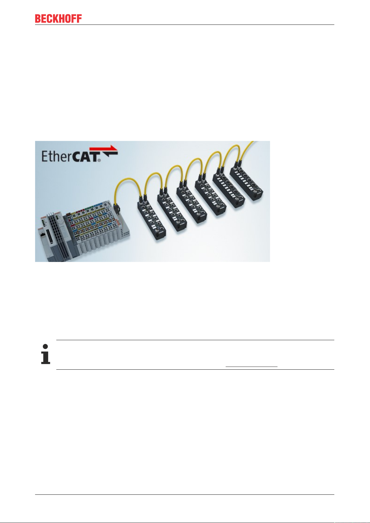
The EtherCAT system has been extended with EtherCAT Box modules with protection class IP67. Through
the integrated EtherCAT interface the modules can be connected directly to an EtherCAT network without an
additional Coupler Box. The high-performance of EtherCAT is thus maintained into each module.
The extremely low dimensions of only e.g.126x30x26.5mm are identical to those of the Fieldbus Box
extension modules. They are thus particularly suitable for use where space is at a premium. The small mass
of the EtherCAT modules facilitates applications with mobile I/O interface (e.g. on a robot arm). The
EtherCAT connection is established via screened M8 connectors.
Fig.1: EtherCAT Box modules extend the EtherCAT system with IP67 protection
The robust design of the EtherCAT Box modules enables them to be used directly at the machine. Control
cabinets and terminal boxes are now no longer required. The modules are fully sealed and therefore ideally
prepared for wet, dirty or dusty conditions.
Pre-assembled cables significantly simplify EtherCAT and signal wiring. Very few wiring errors are made, so
that commissioning is optimized. In addition to pre-assembled EtherCAT, power and sensor cables, fieldconfigurable connectors and cables are available for maximum flexibility. Depending on the application, the
sensors and actuators are connected through M8 or M12 connectors.
Basic EtherCAT documentation
You will find a detailed description of the EtherCAT system in the Basic System Documentation for
EtherCAT, which is available for download from our website (www.beckhoff.com) under Downloads.
EP2918 9Version: 1.1.0
Page 10
Product description
3 Product description
3.1 EP2918-0032
The EP2918-0032 is an EtherCAT Box with digital outputs for 24VDC actuators. The EtherCAT Box has 8
fail-safe outputs, each with a maximum output current of 2A (at 24VDC).
The EP2918-0032 meets the requirements of the following standards:
◦ EN 61508:2010 (SIL 3)
◦ EN 62061:2005/A2:2015 (SIL CL 3)
◦ EN ISO 13849-1:2015 (Cat. 4, PL e)
Fig.2: EP2918-0032 – TwinSAFE EtherCAT Box with 8 fail-safe outputs
The TwinSAFE EtherCAT Box has the usual design of an EtherCAT Box with a width of 60mm and a height
of 150mm.
EP291810 Version: 1.1.0
Page 11
Product description
3.2 Intended use
WARNING
Caution - Risk of injury!
TwinSAFE components may only be used for the purposes described below!
The TwinSAFE EtherCAT Box expands the application range of the Beckhoff system with functions that
enable it to be used for machine safety applications. The TwinSAFE Boxes are designed for machine safety
functions and directly associated industrial automation tasks. They are therefore only approved for
applications with a defined fail-safe state. This safe state is the wattless state. Fail-safety according to the
relevant standards is required.
The TwinSAFE EtherCAT Box allows the connection of:
24VDC actuators such as
• contactors, protective door switches with tumblers, valves etc.
WARNING
The fail-safe principle!
The basic rule for a safety system such as TwinSAFE is that failure of a part, a system component or the
overall system must never lead to a dangerous condition. The safe state is always the switched off and wattless state.
WARNING
Power supply from SELV/PELV power supply unit!
The TwinSAFE components must be supplied with 24VDC by an SELV/PELV power supply unit with an output voltage limit U
of 36VDC. Failure to observe this can result in a loss of safety.
max
WARNING
System limits
The TÜV SÜD certificate applies to this TwinSAFE component, the function blocks available in it, the documentation and the engineering tool. TwinCAT 3.1 and the TwinSAFE Loader are permitted as engineering
tools. Any deviations from these procedures or tools, particularly externally generated xml files for TwinSAFE import or externally generated automatic project creation procedures, are not covered by the certificate.
WARNING
Commissioning test
Before the EP2918-0032 can be used for the safety task, the user must carry out a commissioning test so
that sensor and actuator wiring faults can be ruled out.
CAUTION
Follow the machinery directive!
The TwinSAFE components may only be used in machines as defined in the machinery directive.
CAUTION
Ensure traceability!
The buyer has to ensure the traceability of the device via the serial number.
EP2918 11Version: 1.1.0
Page 12

Product description
3.3 Technical data
Product designation EP2918-0032
Fieldbus EtherCAT
Number of outputs 8
Connection of the outputs M12
Status display 8 (one green LED per output), 5 diagnostic LEDs, 2 LEDs for Us/Up, 2 LEDs
Response time
(read input/write to E-bus)
Watchdog time adjustable from 2ms to 60s
Fault response time ≤ watchdog time
Cable length between actuator and EtherCAT Box Unshielded: 100m max. (at 0.75 or 1 mm²)
Safe outputs max. 2.0A (at 24VDC) per channel
Outputs (functional) Functional overcurrent cut-off of the output driver:
Input process image 6 bytes (via FSoE if using the default project)
Output process image 7 bytes (via FSoE if using the default project)
EP2918 supply voltage 24VDC (–15%/+20%)
Current consumption US
(8 output channels switched)
Current consumption U
(8 output channels switched, plus load current)
Power dissipation of the EtherCAT Box typically 4.9watts
Electrical isolation (between the channels) no
Electrical isolation (between the channels and Ether-
CAT)
Insulation voltage (between the channels and Ether-
CAT, under common operating conditions)
Dimensions (WxHxD) 60(+0.5)mmx150(+0.5)mmx26.5mm
Housing material PBT+PET (Valox 855)
Sealing compound Polyurethane PU552L
Weight approx.470g
Permissible ambient temperature
(operation)
Permissible ambient temperature
(transport/storage)
Permissible air pressure
(operation/storage/transport)
Inadmissible operating conditions TwinSAFE EtherCAT boxes must not be used under the following conditions:
EMC tests according to EN61326-3-1:2017(SIL3)
Vibration resistance conforms to EN60068-2-6
Shock resistance conforms to EN60068-2-27
Protection class (when screwed together) IP67 (according to EN 60529)
Correct installation position variable
Approvals CE, TÜV SÜD
P
for EtherCAT Link/Act
typically: 4ms (in the default setting without local TwinSAFE logic),
maximum: see fault response time
Shielded: 100m max. (at 0.75 or 1 mm²)
Diagnostic thresholds:
>4.7V -> high signal is detected
<1.0V -> low signal is detected
typically between 2.9A and 6.3A
(this overcurrent cut-off is implemented purely functionally and cannot be
loaded from a safety aspect)
8 channels occupied: typically 120mA
0 channels occupied: typically 80mA
(provide a 4A fuse)
8 channels occupied: approx. 70mA
0 channels occupied: approx. 20mA
(provide a 16A fuse)
yes
Insulation tested with 500V
Flame Class: V-0
Flame Class: V-0
-25°C to +60°C
-40°C to +85°C
750hPa to 1100hPa
(this is equivalent to an altitude of approx. -690m to 2450m above sea level
assuming an international standard atmosphere)
• under the influence of ionizing radiation (exceeding the natural
background radiation)
• in corrosive environments
IEC61131-2:2017 chapter 6.2 and 7 (ZoneB)
5 Hz ≤ f < 8.4 Hz (3.5 mm peak)
8.4 Hz ≤ f < 150 Hz (10 m/s2 peak)
15g with pulse duration 11ms in all three axes
DC
EP291812 Version: 1.1.0
Page 13

Product description
Derating table for altitudes above 2000m
The derating table (table 8) from the IEC61131-2:2017 standard can be referred to for the use of the
TwinSAFE components above the specified maximum altitude.
Altitude in m Derating factor for the temperature
0 to 2000
2
1.0
1
3000 0.9
4000 0.8
5000 0.7
Note: Linear interpolation is permissible between the altitudes
1)
Ambient temperature of the device at an altitude of 2000m
2)
The air pressure and air density increase as the altitude decreases. Therefore the derating factor for 0 to
2000 m (1.0) is used for altitudes below sea level.
Calculation example
In the following example the calculation is performed for a TwinSAFE component at an operating altitude of
4000m.
Permissible ambient temperature up to 2000 m above sea level = 55°C
Permissible ambient temperature up to 4000m above sea level = 55°C * 0.8 = 44°C
CAUTION
Compliance with the temperature limits
The TwinSAFE component has a maximum internal temperature at which a switch-off takes place. This is
designed for the maximum permissible ambient temperature. If the derating factor for the temperature for
higher altitudes is used, the user is solely responsible for ensuring that the calculated maximum ambient
temperature is complied with.
3.4 Safety parameters
Characteristic numbers EP2918-0032
Lifetime [a] 20
Proof test interval [a] not required
PFH
D
4.16E-09
PFD 2.00E-05
MTTF
D
high
DC high
Performance level PL e
Category 4
HFT 1
Element classification
1)
Special proof tests throughout the service life of the EtherCAT Box are not required.
2)
Classification according to IEC 61508-2:2010 (see chapters 7.4.4.1.2 and 7.4.4.1.3)
2
Type B
1
The EP2918-0032 EtherCAT Box can be used for safety-related applications according to IEC61508:2010
up to SIL3 and ENISO13849-1:2015 up to PLe(Cat4).
Further information on calculating or estimating the MTTFD value from the PFHD value can be found in the
TwinSAFE Application Guide or in ENISO13849-1:2015, TableK.1.
In terms of safety-related parameters, the Safety-over-EtherCAT communication is already considered with
1% of SIL3 according to the protocol specification.
EP2918 13Version: 1.1.0
Page 14
Product description
3.5 Safe output
The safe outputs are implemented as a single channel per module. It is essential to pay attention to the
following note if two or more outputs run in a common sheathed cable.
DANGER
Clocked signals inside a sheathed cable
If clocked signals from different modules are used inside a single sheathed cable, then a module error such
as a cross-circuit or external power supply must lead to the switch-off of all of these modules. This is
achieved by setting the Module Fault Link active parameter for all modules involved. This parameter is set
to TRUE by default.
3.6 Dimensions
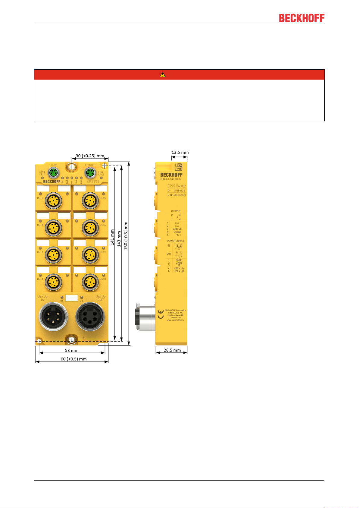
Fig.3: EP2918 Dimensions
The EP2918-0032 module has the following dimensions:
Width 60.0(+0.5)mm
Height 150.0(+0.5)mm
Depth 26.5 mm
When fully wired, the connected cables increase the total depth of the module.
EP291814 Version: 1.1.0
Page 15

Operation
4 Operation
4.1 Environmental conditions
Please ensure that the TwinSAFE Boxes are only transported, stored and operated under the specified
conditions (see technical data)!
WARNING
Risk of injury!
The TwinSAFE EtherCAT boxes must not be used under the following conditions.
• under the influence of ionizing radiation (that exceeds the level of the natural environmental radiation)
• in corrosive environments
NOTE
Electromagnetic compatibility
The TwinSAFE components comply with the current standards on electromagnetic compatibility with regard
to spurious radiation and immunity to interference in particular.
However, in cases where devices such as mobile phones, radio equipment, transmitters or high-frequency
systems that exceed the interference emissions limits specified in the standards are operated near TwinSAFE components, the function of the TwinSAFE components may be impaired.
4.2 Installation
4.2.1 Fixing
NOTE
Protect connectors against soiling!
Protect all connections from contamination during installation and operation of the modules! Protection
class IP67 is only guaranteed if all cables and plug connectors are connected, and unused connections are
protected with the appropriate cover plugs!
Connector sets see catalog.
• Modules with narrow housing are installed with two M3 screws.
• Modules with wide housing are installed with two M3 screws in the mounting holes in the corners or
two M4 screws in the central fastening holes (see also chapter Power connection and grounding).
• The bolts must be longer than 15mm. The fastening holes in the modules have no thread.
• Note when mounting that the overall height is increased further by the fieldbus connections.
4.2.2 Connection
4.2.2.1 Nut torque for connectors
M8 connector
We recommend fastening the M8 connector with a torque of 0.4Nm. A max. torque of 0.5Nm is also
permissible if using a torque screwdriver (Beckhoff article ZB8800).
EP2918 15Version: 1.1.0
Page 16
Operation
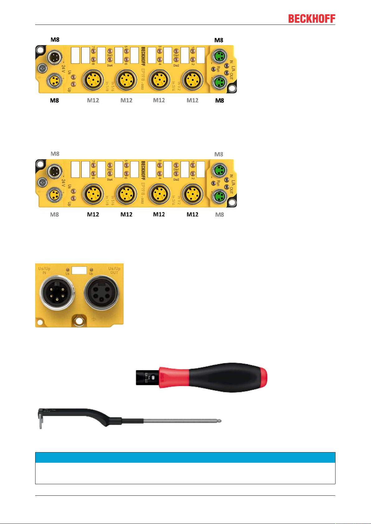
Fig.4: EtherCAT Box with M8 plug connectors
M12 connector
We recommend fastening the M12 connector with a torque of 0.6Nm.
Fig.5: EtherCAT Box with M8 and M12 connectors
7/8" plug connectors
We recommend fastening the 7/8" plug connectors with a torque of 1.5Nm.
Fig.6: 7/8" plug connectors
Torque wrench
Fig.7: Torque wrench ZB8801
NOTE
Ensure the proper torque is used
Use torque wrenches available from Beckhoff to tighten the connectors (see accessories)!
EP291816 Version: 1.1.0
Page 17
Operation
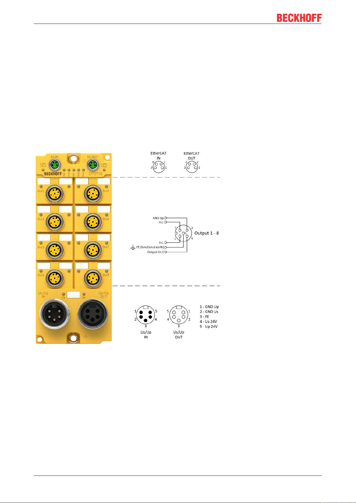
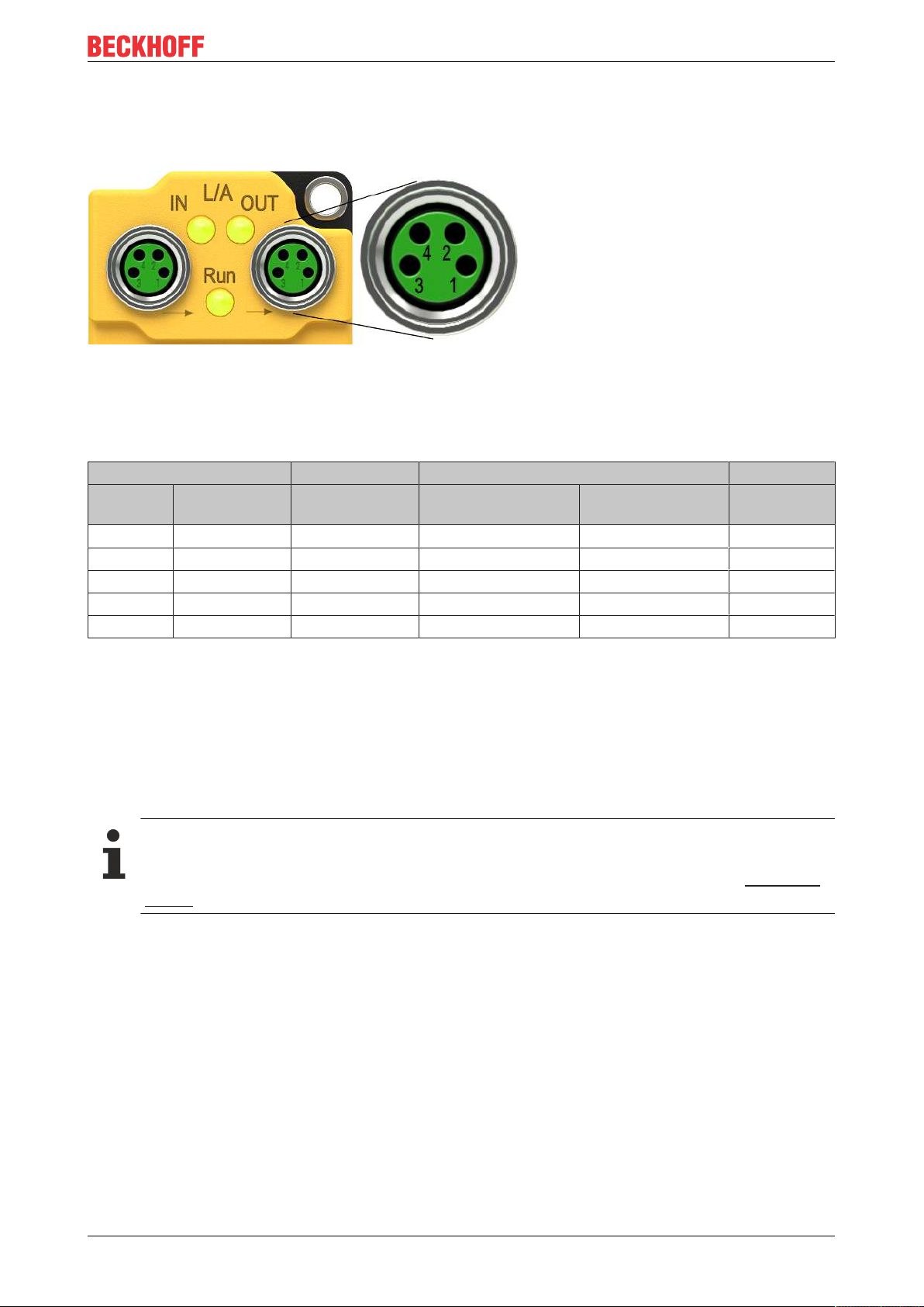
4.2.2.2 EtherCAT connection
The EtherCAT Box (EPxxxx) has two M8 connectors marked green for the incoming and outgoing EtherCAT
connection.
Fig.8: EtherCAT connection 30 mm housing M8
Connection
There are various different standards for the assignment and colors of connectors and cables for EtherCAT.
EtherCAT Connector Cable Standard
Signal Description M8 ZB9010, ZB9020,
ZK1090-6292
Tx + Transmit Data+ Pin 1 yellow
Tx - Transmit Data- Pin 4 orange
Rx + Receive Data+ Pin 2 white
Rx - Receive Data- Pin 3 blue
1
1
1
1
Shield Shield Housing Shield Shield Shield
ZB903x,
ZK1090-31xx
orange/white
orange
blue/white
blue
2
2
2
TIA-568B
2
white/orange
orange
white/green
green
1)
Core colors according to EN61918
2)
Core colors
4.2.2.3 EtherCAT cables
For connecting EtherCAT devices only Ethernet cables that meet the requirements of at least category 5
(CAT5) according to EN 50173 or ISO/IEC 11801 should be used.
Wiring recommendations
Detailed recommendations for EtherCAT wiring can be found in the documentation "Design recommendations for EtherCAT/Ethernet infrastructure", which is available for download from www.Beck-
hoff.de.
EtherCAT uses four cable wires for signal transmission. Due to automatic cable detection (auto-crossing)
symmetric (1:1) or cross-over cables can be used between EtherCAT devices from BECKHOFF.
4.2.2.4 Power connection and grounding
This chapter provides you with basic information about the power supply and grounding of the EP2918-0032
TwinSAFE EtherCAT Box. In particular, please note that the General information on connecting the
functional earth only serves as an example.
Supply voltages (power connection)
The supply and distribution of the supply voltages takes place via the connections:
• Us/Up IN for feeding in the supply voltages
• Us/Up OUT for distribution of the supply voltages.
EP2918 17Version: 1.1.0
Page 18

Operation
Both connections have a 7/8" thread and are located to the left (Us/Up IN) and right (Us/Up OUT) of the
TwinSAFE EtherCAT Box (see figure: EP2918 - power connection).
Information: An overview of pin assignment for the two connections can be found later in this chapter.
General information for connecting the functional earth
The grounding lugs of the EP2918 are internally connected to the safe outputs (pin 5 of the M12
connections).
To provide functional earthing , if possible the connection should:
• have a large surface
• have low resistance and
• be permanent.
In order to establish a permanent connection, all operating states of the machine, such as vibrations, must
be taken into account.
The connection can be established using the following two methods:
1. via a bolted connection from the TwinSAFE-EtherCAT Box to the machine bed
2. through a ring terminal (hole dia. 4.3 mm) with cable connection to the functional earth
A grounding lug is available at the upper and lower mounting points (hole dia. 5 mm for M4 thread) on the
housing.
NOTE
Connecting the functional earth
The functional earth connection should have low resistance and a large surface.
EP2918 – Power connection
Contact Voltage
1 GND Up
2 GND Us
3
7/8" connector pin assignment
Connecting the functional earth
4 Control voltage Us, +24VDC (provide a 4A fuse)
5 Peripheral voltage Up, +24VDC (provide a 16A fuse)
The contacts of the 7/8" plug connectors can conduct a maximum current of 16A.
Two LEDs indicate the status of the supply voltages.
EP291818 Version: 1.1.0
Page 19

Operation
NOTE
Do not confuse the power port with EtherCAT port!
Never connect the power cables (M8, 24VDC) to the green-marked EtherCAT sockets of the EtherCAT Box
Modules. This can cause the destruction of the modules!
Control voltage Us
The fieldbus and the processor logic are supplied from the 24VDC control voltage Us. The control voltage is
electrically isolated from the fieldbus circuitry.
Peripheral voltage Up
The peripheral voltage Up supplies the digital safe outputs.
Redirection of the supply voltages
The power IN and OUT connections are bridged in the module. Hence, the supply voltages Us and Up can
be passed from EtherCATBox to EtherCATBox in a simple manner.
CAUTION
Note the maximum current!
Also ensure when forwarding the supply voltages Us and Up that the maximum permissible current of 16A
for each contact of the 7/8" plug connector is not exceeded!
EP2918 19Version: 1.1.0
Page 20

Operation
4.2.2.5 Signal connection for outputs
The EP2918 has 8 fail-safe outputs, each with a maximum output current of 2.0A (at 24VDC).
Fig.9: EP2918 – safe outputs 1 to 8
Fig.10: PinOut safe output
EP291820 Version: 1.1.0
Page 21

M12 connection Contact Channel Signal
1 1 - not connected
2 not connected
3 1 GND Up
4 Output 1
5 - Functional earth FE
2 1 - not connected
2 not connected
3 2 GND Up
4 Output 2
5 - Functional earth FE
3 1 - not connected
2 not connected
3 3 GND Up
4 Output 3
5 - Functional earth FE
4 1 - not connected
2 not connected
3 4 GND Up
4 Output 4
5 - Functional earth FE
5 1 - not connected
2 not connected
3 5 GND Up
4 Output 5
5 - Functional earth FE
6 1 - not connected
2 not connected
3 6 GND Up
4 Output 6
5 - Functional earth FE
7 1 - not connected
2 not connected
3 7 GND Up
4 Output 7
5 - Functional earth FE
8 1 - not connected
2 not connected
3 8 GND Up
4 Output 8
5 - Functional earth FE
Operation
Functional earth
The functional earth on pin 5 of the M12 connections of the outputs is internally connected to the
grounding lugs of the EtherCAT Box.
4.2.2.6 Overvoltage protection
If protection against overvoltage is necessary in your system, provide a protective circuit (surge filter) against
overvoltage for the power supply to the EtherCAT Box.
4.2.3 EP2918 temperature measurement
The temperature measurement of the TwinSAFE EtherCAT Box consists of a single EtherCAT Box that is
wired with corresponding supply and communication cables. The inputs and/or outputs of the EtherCAT Box
are switched on for the test.
EP2918 21Version: 1.1.0
Page 22

Operation
NOTE
External heat sources / radiant heat / impaired convection
The maximum permissible ambient temperature of 60°C was checked with the example configuration described above. Impaired convection or an unfavorable location near heat sources may have a negative effect on the internal heating of the TwinSAFE components.
The key parameter is always the maximum permitted internally measured temperature of 95°C, above
which the TwinSAFE components switch to safe state and report an error. The internal temperature can be
read from the TwinSAFE components via CoE.
4.2.4 Signal cables
Permitted cable length
Fig.11: EP2918 signal cables
When connecting a single switching contact via its own continuous cabling (or via a sheathed cable), the
maximum permitted cable length with test pulses activated is 100 meters.
The use of contact points, connectors or additional switching contacts in the cabling reduces the maximum
propagation.
EP291822 Version: 1.1.0
Page 23

Operation
Cable routing
Fig.12: Cable routing
NOTE
Route the signal cable separately
The signal cable must be routed separately from potential sources of interference, such as motor supply cables, 230 VAC power cables etc.!
Interference caused by cables routed in parallel can influence the signal form of the test pulses and thus
cause diagnostic messages (e.g. sensor errors or OpenLoad errors).
D: Distance between the cable ducts should be as large as possible
blue arrows: signal line
red arrows: potential source of interference
The common routing of signals together with other clocked signals in a common cable also reduces the
maximum propagation, since crosstalk of the signals can occur over long cable lengths and cause diagnostic
messages.
EP2918 23Version: 1.1.0
Page 24

Operation
4.3 Configuration of the EP2918 in TwinCAT
CAUTION
Do not change CoE objects!
Do not change any of the CoE objects in the TwinSAFE terminals. Any modifications (e.g. via TwinCAT) of
the CoE objects will permanently set the terminals to the Fail-Stop state or lead to unexpected behavior of
the terminals!
4.3.1 Adding an EtherCAT device
See TwinCAT automation software documentation.
4.3.2 Inserting an EP2918
An EP2918 is inserted in exactly the same way as any other Beckhoff EtherCAT Box. Open the TwinSAFE
Fieldbus Boxes item in the list and select the EP2918.
Fig.13: Inserting an EP2918
4.3.3 Using the integrated TwinSAFE Logic functions
On delivery, the EP2918 behaves like a safe TwinSAFE I/O slave, which can be used as an alias device
within a TwinSAFE Logic, e.g. EL6910.
Alternatively, the local logic function of the EP2918 can be used. To this end please create a TwinSAFE
project in the Safety Editor and select the EP2918 as the target system. Further information on creating a
project can be found in the EL6910 documentation and the description of the function blocks under http://
www.beckhoff.de/german/download/twinsafe.htm.
In order to be able to use the EP2918 again as a safe TwinSAFE I/O slave, please delete the logic, the
mapping and the parameter data on the EtherCAT Box and switch the voltage off and on again.
EP291824 Version: 1.1.0
Page 25

Fig.14: EP2918 - Delete Project Data
4.3.4 Project design limits of the EP2918
Project design limits
The maximum project design size of the EP2918 is limited by the available memory. This is managed dynamically. The values specified in the following table are therefore only guide values and
may differ from the actual values, depending on the safety project.
Operation
NOTE
Execution time of the logic function
Compared to the EL6910 with an identical logic program, the execution time will be typically longer as the
safe I/O signals have to be processed in addition. Accordingly this also affects the processing of the I/O signals, as they can only be evaluated less frequently as the size of the project increases.
Process image size max. 1486bytes per data direction
(Max. memory size 0x1E00 for 3 buffers, i.e. with the same size of
input and output process data a maximum size of 1280 bytes per
data direction results. Only even-numbered start addresses are
possible, therefore padding bytes may have to be included.)
TwinSAFE connections maximum 212 (Maximum 255 CRCs in total - 1 CRC is required for
a TwinSAFE connection with 1 or 2 bytes of safe data.)
Safe data per TwinSAFE connection maximum 126bytes (telegram length 255bytes)
TwinSAFE function blocks maximum 512 (For using ESTOP function blocks with complete
input and output mapping. Other function blocks may lead to a
lower maximum number.)
TwinSAFE groups maximum 128
TwinSAFE user maximum 40
Standard PLC inputs dynamic (memory-dependent), max. 1483bytes
Standard PLC outputs dynamic (memory-dependent), max. 1483bytes
NOTE
Project planning
TwinCAT 3.1 Build 4022.28 or later is required for the use of the internal logic functions. If the EP2918 is
used as a TwinSAFE slave with the default project, at least an EL6910, EK1960 or newer logic components
are required as a TwinSAFE master.
EP2918 25Version: 1.1.0
Page 26

Operation
4.3.5 Address settings on the TwinSAFE EtherCAT Box
Fig.15: EtherCAT Box - Rotary switches on the underside
The TwinSAFE address of the Box must be set using the three rotary switches on the underside of the
TwinSAFE-EP Box. TwinSAFE addresses between 1 and 4095 are available.
Rotary switch Address
1 (bottom) 2 (center) 3 (top)
0 0 1 1
0 0 2 2
0 0 3 3
… … … …
0 0 F 15
0 1 0 16
0 1 1 17
… … … …
0 F F 255
1 0 0 256
1 0 1 257
… … … …
F F F 4095
WARNING
TwinSAFE address
Each TwinSAFE address must be unique within a network!
The address 0 is not a valid address.
EP291826 Version: 1.1.0
Page 27

Operation
4.3.6 Alias devices
The communication between the safety logic and the I/O level is realized via an alias level. At this alias level
(subnode Alias Devices) corresponding alias devices are created for all safe inputs and outputs, and also for
standard signal types. For the safe inputs and outputs, this can be done automatically via the I/O
configuration.
The connection- and device-specific parameters are set via the alias devices.
Fig.16: Starting the automatic import from the I/O configuration
If the automatic import is started from the I/O configuration, a selection dialog opens, in which the individual
terminals to be imported can be selected.
Fig.17: Selection from the I/O tree
The alias devices are created in the safety project when the dialog is closed via OK.
Alternatively, the user can create the alias devices individually. To this end select Add and New item from
the context menu, followed by the required device.
EP2918 27Version: 1.1.0
Page 28

Operation
Fig.18: Creating alias devices by the user
EP291828 Version: 1.1.0
Page 29

Operation
4.3.7 EP2918 parameters
After creating the alias device, it can be parameterized according to the user specifications. The FSoE
address is set under the Linking tab, and the link to the physical device is created.
Fig.19: EP2918 – Linking tab
Name Description
FSoE address Parameterized FSoE address (to be set by the user)
External safe address currently not supported
Linking mode • Automatic (automatic linking to the physical device)
• Manual (manual linking, e.g. to network variables)
• Local (signals are used in the local logic)
Physical device Link to the TwinSAFE component within the TwinCAT solution
DIP switch DIP or rotary switch address read from the TwinSAFE component
Input: Full name In manual mode:
Display of the variables below the TwinSAFE Logic, e.g. EL6910
Input: Linked to: In manual mode:
Display of the linked variables
Output: Full name In manual mode:
Display of the variables below the TwinSAFE Logic, e.g. EL6910
Output: Linked to In manual mode:
Display of the linked variables
Name In manual mode:
Name of the TwinSAFE message below the TwinSAFE Logic and for the info
data
EP2918 29Version: 1.1.0
Page 30

Operation
Under the Connection tab you can make further settings, e.g. the mapping of the info data or the behavior in
case of a module error.
Fig.20: EP2918 - Connection tab
Name Description
Conn. no. Connection number (issued by the system)
Conn. Id Connection ID:
Pre-allocated by system, can be changed by the user. The connection ID must be
unique within the TwinCAT project.
Mode • FSoE master (the logic is the master for this alias device)
• FSoE slave (the logic is a slave for this alias device)
Watchdog Setting the watchdog time in ms for this connection. This setting directly affects
the fault response time.
Module Fault is ComError If the checkbox is checked, module error also triggers a ComError, which
switches the TwinSAFE group where the connection was created to the error
state.
Com ERR Ack For each connection, an additional error acknowledge can be configured. In this
case, the connection must also be acknowledged, in addition to the Err Ack for
the respective group.
Map state The connection state is placed in the cyclic process data.
Map diag The connection diagnostics is placed in the cyclic process data.
Map inputs The safe input information of the connection is placed in the cyclic process data.
Map outputs The safe output information of the connection is placed in the cyclic process data.
EP291830 Version: 1.1.0
Page 31

Operation
The Safety Parameters tab contains the parameters of the EP2918 to be set. The outputs are parameterized
via the objects 0x8000 etc.
Fig.21: EP2918 - Parameters
Index Name Default value/
8000:01 ModuloDiagTestPulse
(FSOUT module 1)
8000:02 MultiplierDiagTestPulse
(FSOUT module 1)
8000:03 Standard outputs active
(FSOUT module 1)
8000:04 Diag test pulse active
(FSOUT module 1)
8000:07 Module Fault Link active
(FSOUT Module 1)
8010:01-07 Parameters for FSOUT module 2 see module 1 see module 1
8020:01-07 Parameters for FSOUT module 3 see module 1 see module 1
8030:01-07 Parameters for FSOUT module 4 see module 1 see module 1
8040:01-07 Parameters for FSOUT module 5 see module 1 see module 1
8050:01-07 Parameters for FSOUT module 6 see module 1 see module 1
8060:01-07 Parameters for FSOUT module 7 see module 1 see module 1
8070:01-07 Parameters for FSOUT module 8 see module 1 see module 1
unit
0x00 / integer Modulo value for the frequency of the generation of a test pulse.
0x01 / integer Length of the test pulse in multiples of 400µs
FALSE / Boolean Activation of the logical AND operator of the safe and standard
TRUE / Boolean Activation of test pulses for the corresponding output module
TRUE / Boolean If a module error occurs in this module, a module error is also set
Description
0 -> every time
1 -> every second time
and so on
outputs of the module
for all other output modules of this TwinSAFE component for
which this parameter is also set to TRUE.
EP2918 31Version: 1.1.0
Page 32

Operation
4.3.8 Process image of the EP2918
The process image of EP2918 consists of 6 bytes of input data and 7 bytes of output data. The 6-byte
telegram contains 1 byte of safe data, while the 7-byte telegram contains 2 bytes of safe data.
Fig.22: EP2918 Process image
The assignment of the individual signals in the safe data is listed in the following table.
Name Process image Bit position Description
FSOUT module 1. module fault IN 0.0 Module error information for safe output 1
FSOUT module 2. module fault IN 0.1 Module error information for safe output 2
FSOUT module 3. module fault IN 0.2 Module error information for safe output 3
FSOUT module 4. module fault IN 0.3 Module error information for safe output 4
FSOUT module 5. module fault IN 0.4 Module error information for safe output 5
FSOUT module 6. module fault IN 0.5 Module error information for safe output 6
FSOUT module 7. module fault IN 0.6 Module error information for safe output 7
FSOUT module 8. module fault IN 0.7 Module error information for safe output 8
FSOUT Module1.Output OUT 0.0 Safe output 1
FSOUT Module1.ErrAck OUT 0.1 Error acknowledge for safe output module 1
FSOUT Module2.Output OUT 0.2 Safe output 2
FSOUT Module2.ErrAck OUT 0.3 Error acknowledge for safe output module 2
FSOUT Module3.Output OUT 0.4 Safe output 3
FSOUT Module3.ErrAck OUT 0.5 Error acknowledge for safe output module 3
FSOUT Module4.Output OUT 0.6 Safe output 4
FSOUT Module4.ErrAck OUT 0.7 Error acknowledge for safe output module 4
FSOUT Module5.Output OUT 1.0 Safe output 5
FSOUT Module5.ErrAck OUT 1.1 Error acknowledge for safe output module 5
FSOUT Module6.Output OUT 1.2 Safe output 6
FSOUT Module6.ErrAck OUT 1.3 Error acknowledge for safe output module 6
FSOUT Module7.Output OUT 1.4 Safe output 7
FSOUT Module7.ErrAck OUT 1.5 Error acknowledge for safe output module 7
FSOUT Module8.Output OUT 1.6 Safe output 8
FSOUT Module8.ErrAck OUT 1.7 Error acknowledge for safe output module 8
EP291832 Version: 1.1.0
Page 33

Operation
3 * 3 *
typ Sensor Input Comm Logic Comm Output Actuator
ReactionTime RT RT RT RT RT RT RT= + + + + + +
5 4 3 *1 10 3 *1 3 20 48
typ
ReactionTime ms ms ms ms ms ms ms ms= + + + + + + =
4.4 TwinSAFE reaction times
The TwinSAFE terminals form a modular safety system that exchanges safety-oriented data via the Safetyover-EtherCAT protocol. This chapter is intended to help you determine the system's reaction time from the
change of signal at the sensor to the reaction at the actuator.
Typical response time
The typical response time is the time required for transferring a piece of information from the sensor to the
actuator, when the whole system operates normally, without error.
Fig.23: Typical response time
Definition Description
RT
Sensor
Response time of the sensor, until the signal is made available at the interface. Typically
provided by the sensor manufacturer.
RT
Input
Response time of the safe input, e.g. EL1904 or EP1908. This time can be found in the
technical data. In the case of the EL1904 it is 4ms.
RT
Comm
Response time of the communication. This is typically 3 times the EtherCAT cycle time, since a
new Safety-over-EtherCAT telegram has to be generated before new data can be sent. These
times depend directly on the higher-level standard controller (cycle time of the PLC/NC).
RT
Logic
Response time of the logic terminal. This is the cycle time of the logic terminal and typically
ranges from 500µs to 10ms for the EL6900, depending on the size of the safety project. The
actual cycle time can be read from the terminal.
RT
RT
Output
Actuator
Response time of the output terminal. This is typically between 2 and 3ms.
Response time of the actuator. This information is typically provided by the actuator
manufacturer
WD
Comm
Watchdog time of the communication
The typical response time is based on the following formula:
with
Worst case response time
The worst-case response time is the maximum time required for switching off the actuator in the event of an
error.
EP2918 33Version: 1.1.0
Page 34

Operation
max Comm Comm Actuator
ReactionTime WD WD RT= + +
max
2 *15 20 50ReactionTime ms ms ms= + =
Fig.24: Worst case response time
It is assumed that a signal change takes place at the sensor, and that this is passed to the input. A
communication error occurs just at the moment when the signal is to be passed to the communication
interface. This is detected by the logic once the watchdog time of the communication link has elapsed. This
information should then be passed on to the output, resulting in a further communication error. This fault is
detected at the output once the watchdog time has elapsed, resulting in shutdown.
This results in the following formula for the worst-case response time:
with
EP291834 Version: 1.1.0
Page 35

4.5 Diagnostics
4.5.1 EtherCAT- Fieldbus LEDs
Fig.25: EP2918 Diagnostic LEDs
LED displays
LED Display Meaning
IN Link/Act off no connection to the preceding EtherCAT module
lit LINK: connection to the preceding EtherCAT module
flashes ACT: communication with the preceding EtherCAT module
OUT Link/Act off no connection to the following EtherCAT module
lit LINK: connection to the following EtherCAT module
flashes ACT: Communication with the following EtherCAT module
Run off Status of the EtherCAT module is Init
flashes quickly Status of the EtherCAT module is pre-operational
flashes slowly Status of the EtherCAT module is safe-operational
lit Status of the EtherCAT module is operational
Operation
EP2918 35Version: 1.1.0
Page 36

Operation
4.5.2 Status LEDs
Fig.26: EP2918 Status LEDs
LED Display Meaning
Out 1 on Output 1 is connected
off Output 1 is not connected
Out 2 on Output 2 is connected
off Output 2 is not connected
Out 3 on Output 3 is connected
off Output 3 is not connected
Out 4 on Output 4 is connected
off Output 4 is not connected
Out 5 on Output 5 is connected
off Output 5 is not connected
Out 6 on Output 6 is connected
off Output 6 is not connected
Out 7 on Output 7 is connected
off Output 7 is not connected
Out 8 on Output 8 is connected
off Output 8 is not connected
Us on Control voltage Us is available
off Control voltage Us is not available
Up on Peripheral voltage Up is present
off Peripheral voltage Up is not present
EP291836 Version: 1.1.0
Page 37

Operation
4.5.3 Diagnostic LEDs
Fig.27: EP2918 - Diagnostic LEDs
LED displays
LED lit flashes flickering off
Dia1
(green)
Dia2
(red)
Dia3
(red)
Dia4
(red)
1)
A global fault permanently disables the TwinSAFE component, so that it has to be replaced. A global
shutdown temporarily disables the TwinSAFE component. The error can be reset by switching off and back
on again.
Environment variables,
operating voltage and
internal tests are in the
valid range
• If Dia2 flashes, a logic
error code applies
Together with Dia3 and 4:
Global shutdown1) has
occurred. (see diag history
of the TwinSAFE
components)
Global fault or global
shutdown on µC1
Global fault or global
shutdown on µC2
1)
1)
- Environment variables,
operating voltage and
internal tests are outside
the valid range
• If Dia2 flashes, an
environment error code
applies
Logic or environment
error code according
to Dia1 and tables
below is output
- No global fault or global
- No global fault or global
fault in a safe input
or output module
Together with Dia3 and 4:
Global fault1) has occurred.
(see diag history of the
TwinSAFE components)
shutdown on µC1
shutdown on µC2
1)
1)
Logic error codes of LED Dia2 (if LED Dia1 is lit)
Flashing Code Description
1 Function block error in one of the TwinSAFE groups
2 Communication error in one of the TwinSAFE groups
3 Error combination: Function block and communication
4 General error in one of the TwinSAFE groups
5 Error combination: General and function block
6 Error combination: General and communication
7 Error combination: General, function block and communication
EP2918 37Version: 1.1.0
Page 38

Operation
Environment error codes of LED Dia2 (if LED Dia1 is off)
Flashing Code Description
1 Maximum supply voltage µC1 exceeded
2 Supply voltage µC1 below minimum value
3 Maximum supply voltage µC2 exceeded
4 Supply voltage µC2 below minimum value
5 Maximum internal temperature exceeded
6 Internal temperature below minimum value
7 Valid temperature difference between µC1 and µC2 exceeded
8 not used
9 not used
10 General error
4.5.4 Flash code display
LED Display Description
flashing 400ms ON / 400ms OFF
1 second pause between the flash codes
flickering 50ms ON / 50ms OFF
4.5.5 Diagnostic objects
CAUTION
Do not change CoE objects!
Do not make any modifications to the CoE objects in the TwinSAFE components! Any modifications (e.g.
using TwinCAT) of the CoE objects will permanently set the TwinSAFE components to the Fail-Stop state.
Index F984
CoE object F984
Index Name Meaning Flags Default
F984:01 Voltage C2 Voltage µC2 RO 0
F984:02 Temperature C1 Temperature µC1 RO 0
F984:03 Firmware CRC C1 CRC of the firmware on µC1 RO F984:04 Vendor data CRC C1 CRC of the vendor data on µC1 RO -
Index F985
: Device Info Data C1
hex
currently displays internal temperature and voltage values for the TwinSAFE component.
hex
: Device Info Data C2
hex
dec
dec
CoE object F985
currently displays internal temperature and voltage values for the TwinSAFE component.
hex
Index Name Meaning Flags Default
F985:01 Voltage C1 Voltage µC1 RO 0
F985:02 Temperature C2 Temperature µC2 RO 0
dec
dec
F985:03 Firmware CRC C2 CRC of the firmware on µC2 RO F985:04 Vendor data CRC C2 CRC of the vendor data on µC2 RO -
Diagnostics history
Any errors, which occur during operation of the TwinSAFE component, such as overtemperature or
undervoltage, are entered in the diagnostics history with a corresponding timestamp.
EP291838 Version: 1.1.0
Page 39

Operation
Index F100
The CoE object F100
Index Name Meaning Flags Default
F100:01 Safe Logic State Status of the internal logic:
F100:02 Cycle Counter Life cycle counter, which is incremented with each TwinSAFE logic
The following table contains a description of all values of the index F100
Index Value Description
F100:01 0: OFFLINE In the OFFLINE state no TwinSAFE logic program is loaded. No TwinSAFE groups and no
: FSLOGIC status
hex
shows the current status of the TwinSAFE component.
hex
RO 0
0: OFFLINE
1: RUN
3: SAFE
6: START
8: PREPARE
10: RESTORE
11: PROJECT-CRC-OK
cycle.
SubIndex 01
hex
TwinSAFE connections are processed.
1: RUN In the RUN state all TwinSAFE groups and all TwinSAFE connections configured in the
3: SAFE The SAFE state is assumed from the RUN state when the TwinSAFE logic program is
6: START The START state is assumed if the TwinSAFE logic program is loaded but the standard
8: PREPARE The PREPARE state is assumed at the transition from START to RUN or from SAFE to
10: RESTORE In the RESTORE state the loaded TwinSAFE restore program is to be checked by com-
11: PROJECT-CRC-OK The PROJECT-CRC-OK state is assumed once the project CRC of the loaded TwinSAFE
TwinSAFE logic program are processed.
stopped.
If the TwinSAFE logic program is restarted without a new TwinSAFE logic program having
been transferred, the TwinSAFE logic should switch again from SAFE to RUN. All TwinSAFE groups should be initialized with the initial state STOPERROR, so that an error acknowledgement occurs before safe outputs are connected again.
In the SAFE state no TwinSAFE groups and no TwinSAFE connections are processed.
communication channel (e.g. EtherCAT) is not yet in process data exchange or the
process data lengths configured via the standard communication channel do not match the
process data lengths calculated using the TwinSAFE logic program.
The START state is also assumed when a user is logged in for the purpose of deleting the
current TwinSAFE logic program or transferring the user list.
In the START state no TwinSAFE groups and no TwinSAFE connections are processed.
RUN.
In the PREPARE state, the stored data read in from the FRAM is checked and then the
RUN state is assumed.
If an error is detected during checking of the stored data, all TwinSAFE groups assume
the initial state STOPERROR.
If no error is detected during checking of the stored data, all TwinSAFE groups assume
the initial state STOP.
paring its project CRC with the project CRCs read in via the corresponding TwinSAFE
connections.
In the RESTORE state all TwinSAFE connections configured in the TwinSAFE Restore
program are processed.
restore program has been successfully checked via the TwinSAFE connections.
In the PROJECT-CRC-OK state no TwinSAFE groups and no TwinSAFE connections are
processed.
RO 0
.
bin
bin
This CoE object is additionally copied into the cyclic process image of the TwinSAFE component. From
there, this information can be directly linked into the PLC.
Fig.28: Diagnostic object - FSLOGIC Status (F100
) in the process image of the TwinSAFE component
hex
EP2918 39Version: 1.1.0
Page 40

Operation
4.5.6 Cycle time of the safety project
The execution time of the TwinSAFE logic can be read from the CoE objects listed below. To determine the
cycle time, it has to be multiplied with 1.25, because this is the factor used internally for generating a delay
time before the next cycle.
Index FEA0
: CTRL Diag Data
hex
Index Name Meaning Flags Default
FEA0:09 Actual Safety Control
Task Execution Time
Current execution time of the TwinSAFE logic with a
logic state of1(RUN)
RO 0
hex
Cycle time = 1.25 * value
(average value of 64 cycles)
FEA0:0A Min Safety Control
Task Execution Time
Minimum execution time of the TwinSAFE logic with a
logic state of 1(RUN)
RO 0
hex
Cycle time = 1.25 * value
FEA0:0B Max Safety Control
Task Execution Time
Maximum execution time of the TwinSAFE logic with a
logic state of 1(RUN)
RO 0
hex
Cycle time = 1.25 * value
FEA0:15 Actual Safety Control
Task Execution Time
Current execution time of the TwinSAFE logic with a
logic state of<>1
RO 0
hex
Cycle time = 1.25 * value
(average value of 64 cycles)
FEA0:16 Min Safety Control
Task Execution Time
Minimum execution time of the TwinSAFE logic with a
logic state of<>1
RO 0
hex
Cycle time = 1.25 * value
FEA0:17 Max Safety Control
Task Execution Time
Maximum execution time of the TwinSAFE logic with a
logic state of<>1
RO 0
hex
Cycle time = 1.25 * value
Resetting the values
The max. and min. values can be reset by writing a value to the CoE object 0x1C32:08.
4.5.7 Diag History tab
All errors occurring within the TwinSAFE components are stored in their diag history. The diag history can be
viewed by selecting the corresponding TwinSAFE component in the I/O tree structure and then selecting the
Diag History tab. Use the Update History button to fetch the current data from the TwinSAFE component.
Errors within the logic, the function blocks, the connections or the component itself are stored with a
corresponding time stamp.
Fig.29: Diag history
Use the Advanced… button to open the advanced settings. Here, the user can customize the behavior of the
diag history.
EP291840 Version: 1.1.0
Page 41

Operation
Fig.30: Diag history – advanced settings
Advanced Settings
Setting Description
Message Types • disable Info
Messages with the Info status are not saved in the diag history
• disable Warnings
Messages with the Warning status are not saved in the diag history
• disable Errors
Messages with the Error status are not saved in the diag history
Emergency In addition to saving the message in the diag history, an emergency object
is also sent and displayed in the TwinCAT logger window.
Overwrite/Acknowledge Mode This setting is currently not supported.
4.5.8 Diagnosis History
The diagnostic history of the TwinSAFE devices that support this function is implemented in accordance with
the ETG guideline ETG.1020 Chapter 13 "Diagnosis Handling". The diagnostic messages are saved by the
TwinSAFE device in a dedicated CoE object under 0x10F3 and can be read out by the application or by
TwinCAT.
Both the control entries and the history itself can be found in the CoE object 0x10F3. The entry Newest
Message (0x10F3:02) contains the subindex of 0x10F3, which contains the latest diagnostic message, e.g.
0x06 for diagnostic message 1.
EP2918 41Version: 1.1.0
Page 42

Operation
Index 10F3
Diagnosis History
hex
Index (hex) Name Meaning Data type Flags Default
10F3:0 Diagnosis
History
10F3:01 Maximum
Messages
Maximum number of stored messages. A
maximum of 64 messages can be stored.
UINT8 RO 0x40 (64
After that the respective oldest messages are
overwritten.
10F3:02 Newest
Subindex of the latest message UINT8 RO 0x00 (0
Message
10F3:03 Newest
Subindex of the last confirmed message UINT8 RW 0x00 (0
Acknowledged
Message
10F3:04 New
Indicates that a new message is available BOOLEAN RO 0x00 (0
Messages
Available
10F3:05 Flags Set via the startup list. If set to 0x0001, the
diagnostic messages are additionally sent by
UINT16 RW 0x0000
(0
)
dec
emergency to the EtherCAT master
10F3:06 Diagnosis
Diagnosis message 1 BYTE[32] RO {0}
Message 001
... ... ... ... ... ...
10F3:45 Diagnosis
Diagnosis message 64 BYTE[32] RO {0}
Message 064
dec
dec
dec
dec
)
)
)
)
Structure of the diagnosis messages
• DiagCode (4 bytes) – in this case always 0x 0000 E000
• Flags (2 bytes) - diagnosis type (info, warning or error), time stamp and number of parameters
contained (see the following table)
• Text ID (2 bytes) – ID of the diagnosis message as a reference to the message text from the ESI/XML
• Time stamp (8 bytes) – local slave time in ns since switching on the TwinSAFE device
• dynamic parameters (16 bytes) – parameters that can be inserted in the message text (see following
table)
Flags in diagnosis messages
Data type Offset Description
UINT16 Bit 0…3 DiagType (value)
0 Info message
1 Warning message
2 Error message
3…15 reserved
Bit 4 If the bit = 1, the time stamp contained in the message is the local time stamp of the
TwinSAFE device. The age of the diagnosis message can be deduced by calculation
with the current time stamp from the CoE object 0x10F8.
Bit 5…7 reserved
Bit 8…15 Number of parameters in this diagnosis message
EP291842 Version: 1.1.0
Page 43

Dynamic parameters in the diagnosis messages
Type Data type Description
Flags parameter 1 UINT16 Describes the type of parameter 1
Bit 12…15 = 0 Bit 0…11 = data type of parameter 1
0x0001 - BOOLEAN
0x0002 - INT8
0x0003 - INT16
0x0004 - INT32
0x0005 - UINT8
0x0006 - UINT16
0x0007 - UINT32
0x0008 - REAL32
0x0011 - REAL64
0x0015 - INT64
0x001B - UINT64
Text parameters and formats are
specified in ETG.2000.
Parameter 1 Data type in accordance with
flags
Flags parameter 2 UINT16 see Flags parameter 1
Parameter 2 Data type in accordance with
flags
...
Value of parameter 1
Value of parameter 2
Operation
The diagnostic messages are saved in text form in the ESI/XML file belonging to the TwinSAFE device. On
the basis of the Text ID contained in the diagnostic message, the corresponding plain text message can be
found in the respective languages. The parameters can be inserted in the appropriate positions. In the
following example, %x is used for a hexadecimal representation of the parameters.
Fig.31: ESI/XML message text
Via the entry New Messages Available the user receives information that new messages are available. The
messages can be read out via CompleteAccess (a CoE read command for the complete CoE object
0x10F3). The New Messages Available bit is reset after reading the messages.
The sending of emergency messages to the EtherCAT master is activated by adding the CoE object
0x10F3:05 to the startup list (Transition IP, value 0x0001). If new diagnostic messages arrive, they are
entered in object 0x10F3 and additionally sent by emergency to the EtherCAT master.
Fig.32: Startup list
EP2918 43Version: 1.1.0
Page 44

Operation
4.6 Maintenance
Maintenance
The TwinSAFE components are maintenance-free!
Environmental conditions
WARNING
Observe the specified environmental conditions!
Please ensure that the TwinSAFE components are only stored and operated under the specified conditions
(see technical data).
If the TwinSAFE component is operated outside the permitted temperature range it will switch to Global
Shutdown state.
Cleaning
Protect the TwinSAFE component from unacceptable soling during operation and storage!
If the TwinSAFE component was subjected to unacceptable soiling it may no longer be operated!
WARNING
Have soiled terminals checked!
Cleaning of the TwinSAFE component by the user is not permitted!
Please send soiled terminals to the manufacturer for inspection and cleaning!
EP291844 Version: 1.1.0
Page 45

4.7 Service life
The TwinSAFE EtherCAT Boxes have a service life of 20 years.
Due to the high diagnostic coverage within the lifecycle no special proof tests are required.
Datecode
The TwinSAFE EtherCAT Boxes have a datecode (D:), which is structured as follows:
Datecode: WWYYSWHW
Operation
Key:
WW: Calendar week of manufacture
YY: Year of manufacture
SW: Software version
HW: Hardware version
Serial number (S. no.)
In addition, the TwinSAFE EtherCAT Boxes have a unique serial number (S. no.).
Fig.33: EP2918 serial number and data code
Example: Datecode 16180102
Calendar week: 16
Year: 2018
Software version: 01
Hardware version: 02
4.8 Decommissioning
WARNING
Risk of electric shock!
Bring the bus system into a safe, de-energized state before starting disassembly of the devices!
Disposal
The device must be removed for disposal.
Observe the applicable national laws and guidelines for disposal!
• Housing components (Valox 855 - PBT+PET), made from recyclable plastic
• Sealing compound: Polyurethane resin (PU552L)
• Metal parts can be sent for metal recycling.
• Electronic parts such as disk drives and circuit boards must be disposed of in accordance with national
electronics scrap regulations.
EP2918 45Version: 1.1.0
Page 46

Operation
4.9 Firmware update of TwinSAFE products
For TwinSAFE products there is the option of performing a firmware update via the EtherCAT interface. The
complete firmware of the TwinSAFE component is deleted and replaced by a new version.
The latest firmware can be downloaded from the Beckhoff website. The versions are available in an
encrypted form and can only be loaded onto the matching TwinSAFE product. An incorrect firmware file is
rejected by the respective TwinSAFE product.
Prerequisite for a firmware update
DANGER
Put the machine into a safe state!
A firmware update stops the current processing of the firmware of the TwinSAFE product. It is essential that
you switch the TwinSAFE system to the safe state before you start an update.
All safe outputs must be in a safe, de-energized state. If hanging or pulling loads are present on the machine or the TwinSAFE system, these must also be brought into a safe state through external safety measures if necessary.
DANGER
Monitor the machine state!
It is necessary that you have control over the machine, i.e. you can see it and thus ensure that it is in a safe
state and that a firmware update can be carried out without endangering the operators or other personnel.
NOTE
Avoid communication interruptions during the download
Please avoid disconnecting the EtherCAT connection while downloading the firmware under any circumstances. If a communication error does occur, the TwinSAFE product may subsequently be unusable and
must be sent to the Beckhoff Service.
WARNING
Default project for TwinSAFE I/O components with local logic function!
After a firmware update, any implemented default project starts automatically. An EK1960, for example,
would start up as a TwinSAFE I/O slave after a firmware update.
NOTE
Firmware update of TwinSAFE logics
If a firmware update is performed for a TwinSAFE logic component, e.g. on a TwinSAFE logic EL6910, the
safety-related user program must be reloaded to the TwinSAFE logic after the update. After the update the
user administration is set to the default settings.
EtherCAT communication
When an EtherCAT component is updated, it is switched to BOOTSTRAP mode. This can have an
effect on the EtherCAT communication with other EtherCAT devices.
EP291846 Version: 1.1.0
Page 47

Operation
Performing the firmware update
Click the button (1) in the TwinCAT system to enter Config mode. Confirm the query with OK (2). After that a
further window appears which must be confirmed with Yes (Ja) (3). Deactivate the "Free Run" with No (Nein)
(4). The system is now in Configuration mode.
Fig.34: Firmware update of TwinSAFE products - Part 1
To perform the firmware update, select the "Online" tab (6) for the "EtherCAT Device" (5). If you want to
update several components, you can select the corresponding components (7) together; for individual
components, select only these. Subsequently, click with the right mouse button inside the selected area and
select the command "Firmware Update..." (8) in the command overview.
EP2918 47Version: 1.1.0
Page 48

Operation
Fig.35: Firmware update of TwinSAFE products - Part 2
In the place where you have stored the desired firmware version, select the firmware file (9) and click
"Open" (10). Confirm the window that then opens with "OK" (11); the firmware update is then performed.
After successful completion you must click OK (12) in the concluding "Function Succeeded" window. You
can then switch the system back to Run mode and use the TwinSAFE system.
Fig.36: Firmware update of TwinSAFE products - Part 3
EP291848 Version: 1.1.0
Page 49

Appendix
5 Appendix
5.1 Protection classes according to IP code
The levels of protection are defined and divided into different classes in the IEC 60529 standard (DIN EN
60529). The designation follows the scheme below.
1st digit: Protection against ingress of dust and access to hazardous parts
1st digit Meaning
0 Non-protected
1 Protection against access to hazardous parts with back of hand. Protection against ingress of
solid foreign objects = 50 mm diameter
2 Protection against access to hazardous parts with a finger. Protection against ingress of solid
foreign objects = 12.5 mm diameter
3 Protection against access to hazardous parts with a tool. Protection against ingress of solid
foreign objects = 2.5 mm diameter
4 Protection against access to hazardous parts with a wire. Protection against ingress of solid
foreign objects = 1 mm diameter
5 Protection against access to hazardous parts with a wire. Protection against ingress of dust.
Ingress of dust is not prevented completely, although the quantity of dust able to penetrate is
limited to such an extent that the proper function of the device and safety are not impaired
6 Protection against access to hazardous parts with a wire. Dust-proof. No ingress of dust
2nd digit: Protection against ingress of water*
2nd digit Meaning
0 Non-protected.
1 Protection against dripping water.
2 Protection against dripping water when housing tilted up to 15°.
3 Protection against spraying. Water sprayed at an angle of up to 60° from vertical must not have
any adverse effect.
4 Protection against splashing. Water splashing against the housing from any direction must not
have any adverse effects.
5 Protection against jetting.
6 Protection against powerful jetting.
7 Protection against the effects of temporary immersion. The quantity of water being able to
penetrate if the housing is submerged in water for 30 minutes at a depth of 1 m must not have
any adverse effects.
*) These protection classes only define protection against water, not against other liquids.
EP2918 49Version: 1.1.0
Page 50

Appendix
5.2 Support and Service
Beckhoff and their partners around the world offer comprehensive support and service, making available fast
and competent assistance with all questions related to Beckhoff products and system solutions.
Beckhoff's branch offices and representatives
Please contact your Beckhoff branch office or representative for local support and service on Beckhoff
products!
The addresses of Beckhoff's branch offices and representatives round the world can be found on her internet
pages:
http://www.beckhoff.com
You will also find further documentation for Beckhoff components there.
Beckhoff Headquarters
Beckhoff Automation GmbH & Co. KG
Huelshorstweg 20
33415 Verl
Germany
Phone: +49 5246 963 0
Fax: +49 5246 963 198
e-mail: info@beckhoff.com
Beckhoff Support
Support offers you comprehensive technical assistance, helping you not only with the application of
individual Beckhoff products, but also with other, wide-ranging services:
• support
• design, programming and commissioning of complex automation systems
• and extensive training program for Beckhoff system components
Hotline: +49 5246 963 157
Fax: +49 5246 963 9157
e-mail: support@beckhoff.com
Beckhoff Service
The Beckhoff Service Center supports you in all matters of after-sales service:
• on-site service
• repair service
• spare parts service
• hotline service
Hotline: +49 5246 963 460
Fax: +49 5246 963 479
e-mail: service@beckhoff.com
EP291850 Version: 1.1.0
Page 51

5.3 Certificates
Appendix
EP2918 51Version: 1.1.0
Page 52

List of illustrations
List of illustrations
Fig. 1 EtherCAT Box modules extend the EtherCAT system with IP67 protection................................ 9
Fig. 2 EP2918-0032 – TwinSAFE EtherCAT Box with 8 fail-safe outputs............................................. 10
Fig. 3 EP2918 Dimensions .................................................................................................................... 14
Fig. 4 EtherCAT Box with M8 plug connectors...................................................................................... 16
Fig. 5 EtherCAT Box with M8 and M12 connectors............................................................................... 16
Fig. 6 7/8" plug connectors .................................................................................................................... 16
Fig. 7 Torque wrench ZB8801 ............................................................................................................... 16
Fig. 8 EtherCAT connection 30 mm housing M8................................................................................... 17
Fig. 9 EP2918 – safe outputs 1 to 8 ...................................................................................................... 20
Fig. 10 PinOut safe output ....................................................................................................................... 20
Fig. 11 EP2918 signal cables .................................................................................................................. 22
Fig. 12 Cable routing ............................................................................................................................... 23
Fig. 13 Inserting an EP2918 .................................................................................................................... 24
Fig. 14 EP2918 - Delete Project Data...................................................................................................... 25
Fig. 15 EtherCAT Box - Rotary switches on the underside ..................................................................... 26
Fig. 16 Starting the automatic import from the I/O configuration ............................................................. 27
Fig. 17 Selection from the I/O tree........................................................................................................... 27
Fig. 18 Creating alias devices by the user............................................................................................... 28
Fig. 19 EP2918 – Linking tab................................................................................................................... 29
Fig. 20 EP2918 - Connection tab............................................................................................................. 30
Fig. 21 EP2918 - Parameters .................................................................................................................. 31
Fig. 22 EP2918 Process image ............................................................................................................... 32
Fig. 23 Typical response time.................................................................................................................. 33
Fig. 24 Worst case response time ........................................................................................................... 34
Fig. 25 EP2918 Diagnostic LEDs ............................................................................................................ 35
Fig. 26 EP2918 Status LEDs ................................................................................................................... 36
Fig. 27 EP2918 - Diagnostic LEDs .......................................................................................................... 37
Fig. 28 Diagnostic object - FSLOGIC Status (F100hex) in the process image of the TwinSAFE com-
ponent.......................................................................................................................................... 39
Fig. 29 Diag history.................................................................................................................................. 40
Fig. 30 Diag history – advanced settings................................................................................................. 41
Fig. 31 ESI/XML message text ................................................................................................................ 43
Fig. 32 Startup list.................................................................................................................................... 43
Fig. 33 EP2918 serial number and data code ......................................................................................... 45
Fig. 34 Firmware update of TwinSAFE products - Part 1 ........................................................................ 47
Fig. 35 Firmware update of TwinSAFE products - Part 2 ........................................................................ 48
Fig. 36 Firmware update of TwinSAFE products - Part 3 ........................................................................ 48
EP291852 Version: 1.1.0
Page 53

Page 54

More Information:
www.beckhoff.com/EP2918-0032
Beckhoff Automation GmbH & Co. KG
Hülshorstweg 20
33415 Verl
Germany
Phone: +49 5246 9630
info@beckhoff.com
www.beckhoff.com
 Loading...