

Page 1
Operating instructions for
EP1908
TwinSAFE EtherCAT Box with eight fail-safe inputs
Version: 1.2.1
Date: 2015-03-11
Page 2

Page 3

Table of contents
Table of contents
1 Foreword 3
1.1 Notes on the manual 3
1.1.1 Disclaimer 3
1.1.2 Brands 3
1.1.3 Patents 3
1.1.4 Copyright 3
1.1.5 Delivery conditions 3
1.2 Safety instructions 4
1.2.1 Delivery state 4
1.2.2 Operator's obligation to exercise diligence 4
1.2.3 Description of safety symbols 5
1.2.4 Origin of the document 5
1.2.5 Documentation issue status 5
2 System description 6
2.1 EtherCAT Box Modules 6
3 Product description 7
3.1 EP1908-0002 7
3.2 Intended use 8
3.3 Technical data 9
3.4 Safety parameters 10
3.5 Dimensions 10
4 Operation 11
4.1 Installation 11
4.1.1 Safety instructions 11
4.1.2 Transport / storage 11
4.1.3 Address settings on the TwinSAFE EtherCAT Box 12
4.1.4 Mounting 13
4.1.5 Connection 14
4.2 Operating modes 21
4.3 EP1908 process image 23
4.4 Diagnostics 24
4.4.1 Run LED diagnostics 24
4.4.2 Diagnostic objects 25
EP1908-0002 1
Page 4

Table of contents
4.5 EL1908 configuration in the TwinCAT System Manager 27
4.5.1 Adding an EtherCAT device 27
4.5.2 Adding a EP1908 27
4.5.3 Entering a TwinSAFE address and parameters in the System Manager 28
4.6 Maintenance 37
4.6.1 Cleaning 37
4.6.2 Service life 37
4.7 Decommissioning 38
4.7.1 Disposal 38
5 Appendix 39
5.1 Protection classes according to IP code 39
5.1 Beckhoff Support and Service 40
5.1.1 Beckhoff branches and partner companies Beckhoff Support 40
5.1.2 Beckhoff company headquarters 40
5.2 Certificate 41
2
EP1908-0002
Page 5

Foreword
1 Foreword
1.1 Notes on the manual
This description is only intended for the use of trained specialists in control and automation technology
familiar with the applicable national standards. It is essential that the following notes and explanations are
followed when installing and commissioning these components.
The responsible staff must ensure that the application or use of the products described satisfy all the
safety requirements, including all the relevant laws, regulations, guidelines and standards.
1.1.1 Disclaimer
This documentation has been prepared with care. The products described are, however, constantly under
development. For this reason, the documentation may not always have been fully checked for
consistency with the performance data, standards or other characteristics described.
If it should contain technical or editorial errors, we reserve the right to make changes at any time and
without notice.
No claims for the modification of products that have already been supplied may be made on the basis of
the data, diagrams and descriptions in this documentation.
1.1.2 Brands
Beckhoff®, TwinCAT®, EtherCAT®, Safety over EtherCAT®, TwinSAFE® and XFC® are registered
trademarks of and licensed by Beckhoff Automation GmbH.
The use by third parties of other brand names or trademarks contained in this documentation may lead to
an infringement of the rights of the respective trademark owner.
1.1.3 Patents
The EtherCAT technology is patent protected, in particular by the following applications and patents:
EP1590927, EP1789857, DE102004044764, DE102007017835 with the corresponding applications and
registrations in various other countries.
The TwinCAT technology is patent protected, in particular by the following applications and patents:
EP0851348, US6167425 with the corresponding applications and registrations in various other countries.
1.1.4 Copyright
©
Beckhoff Automation GmbH & Co. KG.
The copying, distribution and utilization of this document as well as the communication of its contents to
others without express authorization is prohibited. Offenders shall be held liable for damages. All rights
conferred by patent grant or registration of a utility model or registered design are reserved.
1.1.5 Delivery conditions
In addition, the general delivery conditions of the company Beckhoff Automation GmbH & Co. KG apply.
EP1908-0002 3
Page 6

Foreword
1.2 Safety instructions
1.2.1 Delivery state
All the components are supplied in particular hardware and software configurations appropriate for the
application. Modifications to hardware or software configurations other than those described in the
documentation are not permitted, and nullify the liability of Beckhoff Automation GmbH & Co. KG.
1.2.2 Operator's obligation to exercise diligence
The operator must ensure that
• the TwinSAFE products are only used as intended (see section Product description);
• the TwinSAFE products are only operated in sound condition and in working order (see chapter
Cleaning).
• the TwinSAFE products are operated only by suitably qualified and authorized personnel.
• the personnel is instructed regularly about relevant occupational safety and environmental
protection aspects, and is familiar with the operating instructions and in particular the safety
instructions contained herein.
• the operating instructions are in good condition and complete, and always available for reference
at the location where the TwinSAFE products are used.
• none of the safety and warning notes attached to the TwinSAFE products are removed, and all
notes remain legible.
4
EP1908-0002
Page 7
Foreword
1.2.3 Description of safety symbols
The following safety symbols are used in these operating instructions. They are intended to alert the
reader to the associated safety instructions.
Serious risk of injury!
DANGER
WARNING
CAUTION
Attention
Note
Failure to follow the safety instructions associated with this symbol directly endangers
the life and health of persons.
Caution - Risk of injury!
Failure to follow the safety instructions associated with this symbol endangers the life
and health of persons.
Personal injuries!
Failure to follow the safety instructions associated with this symbol can lead to injuries
to persons.
Damage to the environment or devices
Failure to follow the instructions associated with this symbol can lead to damage to the
environment or equipment.
Tip or pointer
This symbol indicates information that contributes to better understanding.
1.2.4 Origin of the document
The operating instructions for the EP1908-0002 EtherCAT Box were originally written in German. All other
languages are derived from the German original.
1.2.5 Documentation issue status
Version Comment
1.2.1
1.2.0
1.1.2
1.1.1
1.1.0
• Certificate updated
• Company address amended
• Documentation versions added
• DateCode description added
• HFT and element classification according to EN 61508:2010 added
• Clock output currents in the technical data amended
• Notes regarding the M8 and M12 connectors expanded
• Reference to EN 60068-2-29 removed
• First released version
EP1908-0002 5
Page 8
System description
2 System description
2.1 EtherCAT Box Modules
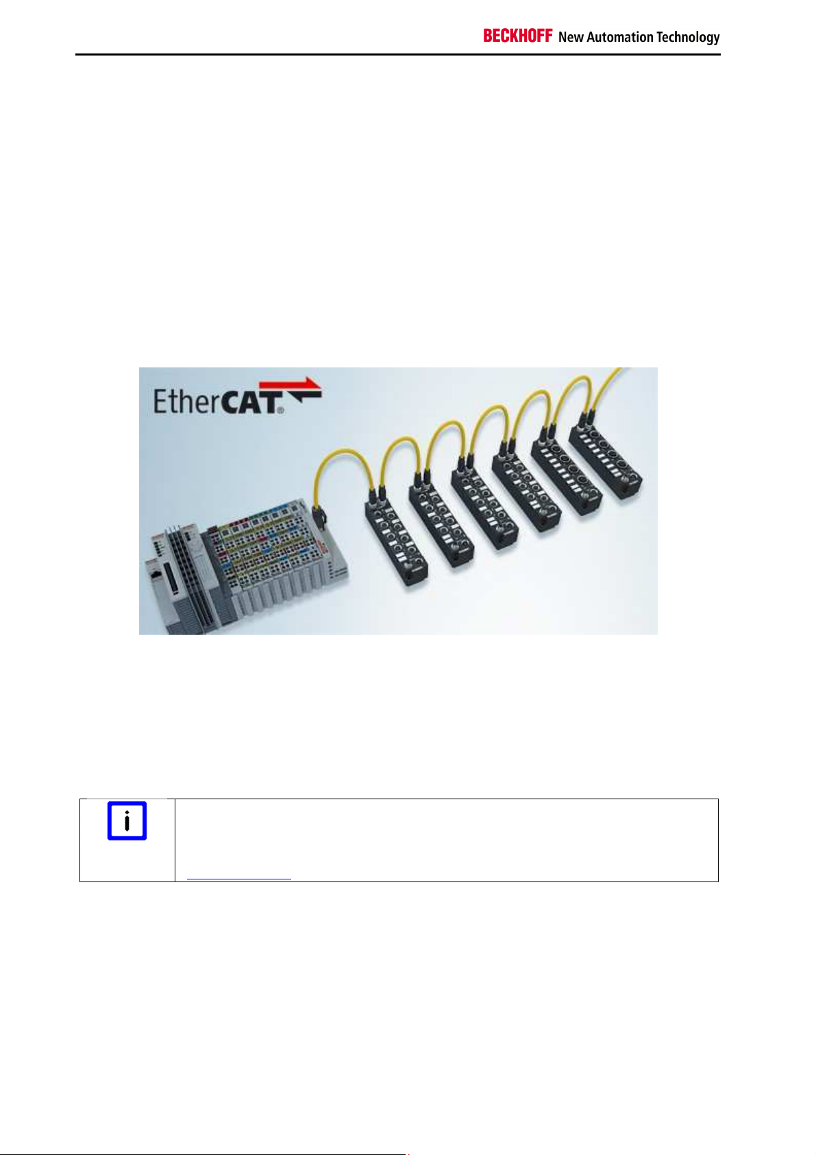
The EtherCAT system has been extended with EtherCAT Box modules with protection class IP 67.
Through the integrated EtherCAT interface the modules can be connected directly to an EtherCAT
network without an additional Coupler Box. The high-performance of EtherCAT is thus maintained into
each module.
The extremely low dimensions of only 126 x 30 x 26.5 mm (H x W x D) are identical to those of the
Fieldbus Box extension modules. They are thus particularly suitable for use where space is at a premium.
The small mass of the EtherCAT modules facilitates applications with mobile I/O interface (e.g. on a robot
arm). The EtherCAT connection is established via screened M8 connectors.
The robust design of the EtherCAT Box modules enables them to be used directly at the machine.
Control cabinets and terminal boxes are now no longer required. The modules are fully sealed and
therefore ideally prepared for wet, dirty or dusty conditions.
Pre-assembled cables significantly simplify EtherCAT and signal wiring. Very few wiring errors are made,
so that commissioning is optimized. In addition to pre-assembled EtherCAT, power and sensor cables,
field-configurable connectors and cables are available for maximum flexibility. Depending on the
application, the sensors and actuators are connected through M8 or M12 connectors.
Basic EtherCAT documentation
Note
You will find a detailed description of the EtherCAT system in the Basic System
Documentation for EtherCAT, which is available for download from our website
(www.beckhoff.de) under Downloads.
6
EP1908-0002
Page 9
Product description
3 Product description
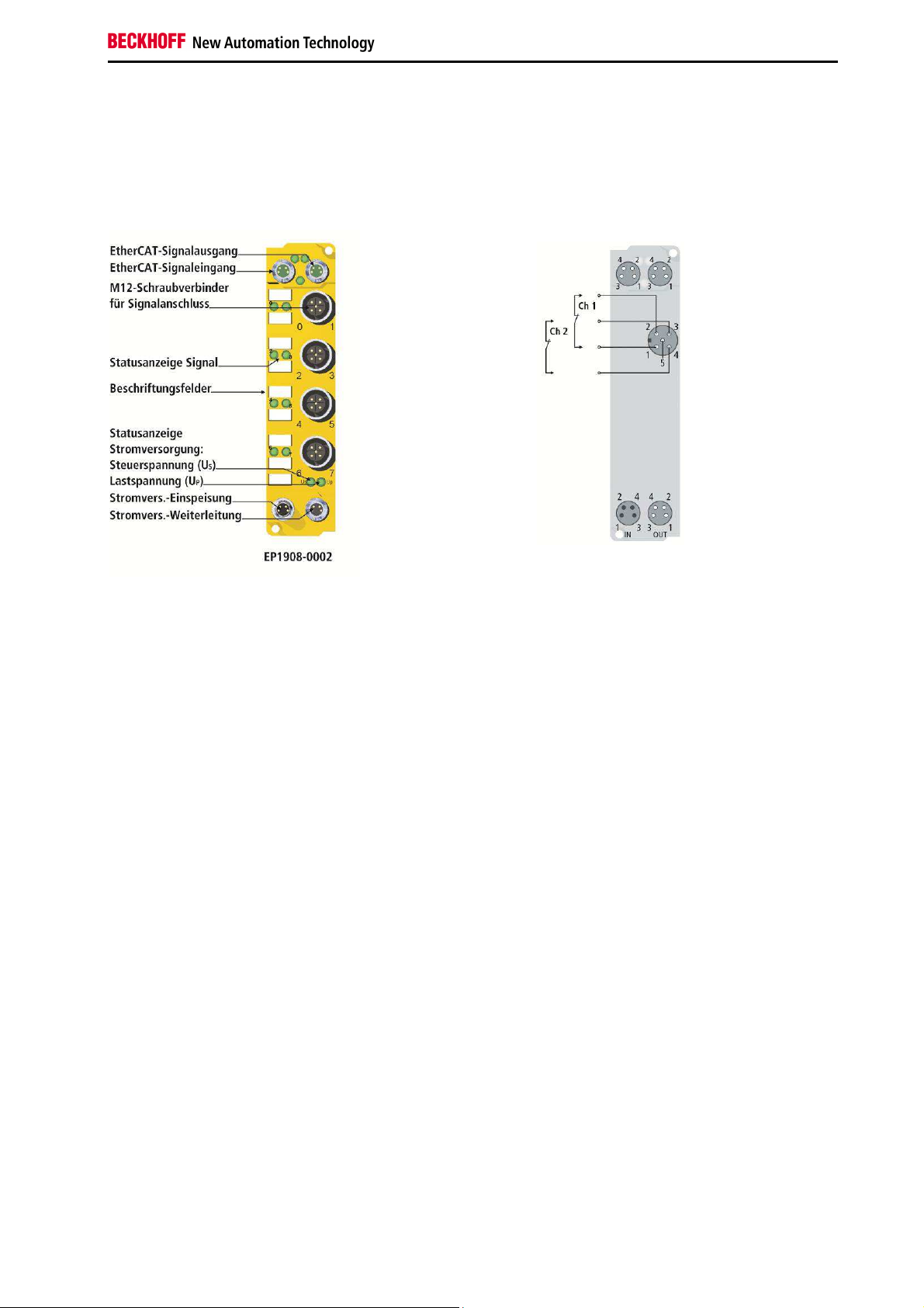
3.1 EP1908-0002
The EP1908-0002 is an EtherCAT Box with digital inputs for 24 VDC encoders or for potential-free
contacts. The EtherCAT Box has eight fail-safe inputs.
In addition to the possibility to read potential-free contacts, the EP1908-0002 also supports the
connection of encoders with OSSD signals whose test pulse length does not exceed 350 µs and of safety
mats that operate based on the cross-circuit principle.
Frequency measurement is also supported, in order to enable standstill and speed monitoring. The
frequency below which a logical 1 is reported at the input is specified in steps of 0.1 Hz. The module
supports a minimum frequency of 2 Hz and a maximum frequency of 500Hz. Frequencies above of 500
Hz result in a diagnostic message for the module. In this case all inputs are set to safe state (logical 0).
This message can be reset through a rising edge of the safe output signal ErrAck of the EP1908-0002.
With a two-channel connection, the EP1908-0002 meets the requirements of EN 61508-1:2010 SIL 3 and
DIN EN ISO 13849-1:2006 (Cat 4, PL e).
The control voltage US supplies the module electronics. The sensors are supplied from the control voltage
Up.
The TwinSAFE EtherCAT Box has the typical design of an EtherCAT Box.
EP1908-0002 7
Page 10
Product description
3.2 Intended use
Caution - Risk of injury!
WARNING
The TwinSAFE EtherCAT Box expands the application range of the Beckhoff system with functions that
enable it to be used for machine safety applications. The TwinSAFE Boxes are designed for machine
safety functions and directly associated industrial automation tasks. They are therefore only approved for
applications with a defined fail-safe state. This safe state is the wattless state. Fail-safety according to the
relevant standards is required.
The TwinSAFE EtherCAT Box allows the connection of:
• 24 VDC sensors such as
emergency stop push buttons, pull cord switches, position switches, two-hand switches, safety
mats, light curtains, light barriers, laser scanners etc.
• initiators and encoders for speed measurement (frequency) with a signal voltage of 24 VDC
WARNING
The TwinSAFE EtherCAT Box may only be used for the purposes described below!
The fail-safe principle
The basic rule for a safety system such as TwinSAFE is that failure of a part, a system
component or the overall system must never lead to a dangerous condition. The safe
state is always the switched off and wattless state.
Follow the machinery directive
CAUTION
CAUTION
The TwinSAFE EtherCAT Box may only be used in machines that meet the
requirements of the Machinery Directive.
Ensure traceability
The buyer has to ensure the traceability of the device via the serial number.
8
EP1908-0002
Page 11

Product description
3.3 Technical data
Product designation EP1908-0002
Fieldbus EtherCAT
Number of inputs 8
Connecting the inputs M12
Status display 8 (one green LED per input)
Reaction time
(Read input/write to E-bus)
Watchdog time adjustable from 2 ms to 60 s
Error reaction time ≤ watchdog time
Frequency range for speed measurement 2 Hz to 500 Hz
Cable length between
sensor and EtherCAT Box
(unshielded) 30 m max.(at 0.75 or 1 mm²)
(shielded) 30 m max.(at 0.75 or 1 mm²)
Output current of the clock outputs typically 10 mA, max. 15 mA
Input process image 6 byte
Output process image 6 byte
Supply voltage for the EP1908 24 VDC (-15%/+20%)
Power consumption Us
(connected with eight potential-free contacts)
Current consumption UP
(connected with eight potential-free contacts)
Power dissipation of the EtherCAT Box typically 3 watts
Electrical isolation (between the channels) no
Electrical isolation (between the channels and
EtherCAT)
Insulation voltage (between the channels and
EtherCAT, under common operating conditions)
Dimensions (W x H x D) 30 mm x 126 mm x 26.5 mm
Housing material PA6-F (polyamide)
Sealing compound polyurethane
Weight approx. 170 g
Permissible ambient temperature (operation) -25 ℃ to +70 ℃
Permissible ambient temperature
(transport/storage)
Permissible air humidity 5 % to 95 %, non-condensing
Permissible air pressure
(operation/storage/transport)
Impermissible operating conditions
EMC immunity/emission according to EN 61000-6-2 / EN 61000-6-4
Vibration / shock resistance according to EN 60068-2-6 / EN 60068-2-27
Shocks 15 g with pulse duration 11 ms in all three axes
Protection class (when screwed together) IP65, IP66, IP67 (according to EN 60529)
Permissible installation position Variable
Approvals CE, TÜV SÜD
typically: 4 ms,
maximally: see error reaction time
8 channels occupied: typically 87 mA
0 channels occupied: typically 80 mA
8 channels occupied: approx. 27 mA
0 channels occupied: approx. 6 mA
yes
insulation tested with 500 VDC
-40 ℃ to +85 °C
750 hPa to 1100 hPa
TwinSAFE EtherCAT boxes must not be used under
the following conditions:
• under the influence of ionizing radiation
• in corrosive environments
EP1908-0002 9
Page 12
Product description
3.4 Safety parameters
Key figures EP1908-0002
Lifetime [a] 20
Prooftest Intervall [a] not required 1)
PFH 1.56E-09
%SIL3 1.56%
PFD 1.06E-04
%SIL3 10.59%
MTTFd [a] >100
Performance level PL e
Category 4
HFT 1
Element classification* Type A
*) Classification according to EN 61508-2:2010 (see chapters 7.4.4.1.2 and 7.4.4.1.3)
The EP1908-0002 EtherCAT Box can be used for safety-related applications according to IEC 61508 up
to SIL3 and EN ISO 13849-1 up to PL e (Cat4).
1)
Special proof tests throughout the service life of the EtherCAT Box are not required.
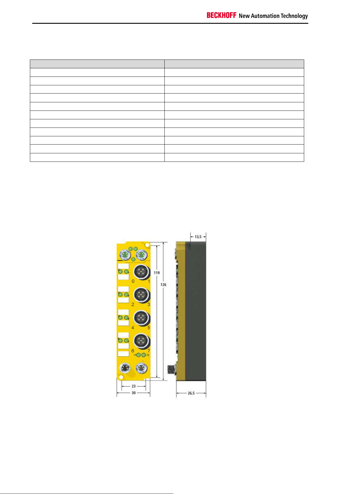
3.5 Dimensions
The EP1908 module has the following dimensions.
Width: 30 mm
Height: 126 mm
Depth: 26.5 mm
When fully wired, the connected cables increase the total depth of the module.
10
EP1908-0002
Page 13
Operation
4 Operation
Please ensure that the TwinSAFE Boxes are only transported, stored and operated under the specified
conditions (see technical data)!
Caution - Risk of injury!
The TwinSAFE EtherCAT boxes must not be used under the following conditions:
WARNING
4.1 Installation
4.1.1 Safety instructions
Read the safety notes in the Foreword of this document before installing and commissioning the
TwinSAFE EtherCAT Box.
• under the influence of ionizing radiation
• in corrosive environments
4.1.2 Transport / storage
When transporting or storing the TwinSAFE EtherCAT Box, always use the original packaging in which it
was delivered.
Note the specified environmental conditions
CAUTION
Please ensure that the digital TwinSAFE EtherCAT Boxes are only transported and
stored under the specified environmental conditions (see technical data).
EP1908-0002 11
Page 14

Operation
4.1.3 Address settings on the TwinSAFE EtherCAT Box
The TwinSAFE address of the box must be set using the three rotary switches at the bottom of the
EP1908-0002 TwinSAFE EP Box. TwinSAFE addresses between 1 and 4095 are available.
Rotary switch Address
1 (left) 2 (centre) 3 (right)
0 0 1 1
0 0 2 2
0 0 3 3
… … … …
0 0 F 15
0 1 0 16
0 1 1 17
… … … …
0 F F 255
1 0 0 256
1 0 1 257
… … … …
F F F 4095
Unique TwinSAFE address
Each TwinSAFE address may only be used once within a network! The address 0 is
WARNING
not a valid address.
12
EP1908-0002
Page 15

Operation
4.1.4 Mounting
Protect connectors against soiling
Note
The modules are mounted with two M3 screws. The bolts must be longer than 15 mm. The fixing holes
are not threaded. Note when mounting that the overall height is increased further by the fieldbus
connections.
4.1.4.1 Mounting rail ZS5300-0001
The mounting rail ZS5300-0001 (500 mm x 129 mm) allows time-saving configuration of the modules.
The rail is made of 1.5 mm thick stainless steel (V2A) and features ready-made M3 threads. Use M5
screws (5.3 mm oblong holes) to attach the rail to the machine.
Protect all connections from contamination during module installation!
Protection class IP67 can only be guaranteed if all cables and connectors are
connected!
Unused connections must be protected with the appropriate connectors (connector
sets see catalog)!
The rail is 500 mm long and enables the installation of 15 modules, with a distance of 2 mm between
them. It can be shortened as required for your particular application.
EP1908-0002 13
Page 16

Operation
4.1.5 Connection
4.1.5.1 Tightening torque for plug connectors
The plug connectors should be tightened with the recommended torque.
Type Connection Nm ft-lb
M8 Power supply, EtherCAT 0.4 0.3
M12 Input signals 0.6 0.44
Torque wrench
Ensure the proper torque is used
Note
Use torque wrenches available from Beckhoff to tighten the plug connectors (see
accessories)!
14
EP1908-0002
Page 17

Operation
4.1.5.2 EtherCAT connection
The EtherCAT Box (EPxxxx) has two M8 connectors marked green for the incoming and outgoing
EtherCAT connection.
Assignment
There are various different standards for the assignment and colors of connectors and cables for
EtherCAT.
EtherCAT Connector Cable Standard
Signal Description M8
ZB9010, ZB9020,
ZK1090-6292
ZB903x,
ZK1090-31xx
TIA-568B
Tx + Transmit Data+ Pin 1 yellow1 orange/white2 white/orange
Tx - Transmit Data- Pin 4 orange1 orange2 orange
Rx + Transmit Data- Pin 2 white1 blue/white2 white/green
Rx - Receive Data- Pin 3 blue1 blue2 green
Screen Shield Housing Screen Screen Screen
1
) Wire colors according to EN 61918
2
) Wire colors
EP1908-0002 15
Page 18

Operation
4.1.5.3 EtherCAT- Fieldbus LEDs
LED displays
LED Display Meaning
IN L/A off no connection to the preceding EtherCAT module
lit LINK: connection to the preceding EtherCAT module
flashing ACT: communication with the preceding EtherCAT module
OUT
L/A
off no connection to the following EtherCAT module
lit LINK: connection to the following EtherCAT module
flashing ACT: Communication with the following EtherCAT module
Run - see section 4.4.1
4.1.5.4 EtherCAT cables
For connecting EtherCAT devices only Ethernet cables that meet the requirements of at least category 5
(CAT5) according to EN 50173 or ISO/IEC 11801 should be used.
Wiring recommendations
Note
Detailed recommendations for EtherCAT wiring can be found in the documentation
"Design recommendations for EtherCAT/Ethernet infrastructure", which is available for
download from www.Beckhoff.com.
EtherCAT uses four cable wires for signal transmission. Due to automatic cable detection (auto-crossing)
symmetric (1:1) or cross-over cables can be used between EtherCAT devices from BECKHOFF.
16
EP1908-0002
Page 19

Operation
4.1.5.5 Power Connection
Two M8 connectors at the low-end of the modules are used for feeding and routing the supply voltages:
• IN: left M8 connector for feeding the supply voltages
• OUT: right M8 connector for routing the supply voltages
• Earthing screw: The earthing screw is installed in the factory. An additional M3 ring cable lug and
the earthing cable are required for the installation.
Pin assignment
Voltage
Contact
1 Control voltage Us, +24 VDC
2 Peripheral voltage Up, +24 VDC
3 GNDS
4 GNDP
Earthing connection
The contacts of the M8 plug connectors can conduct a maximum
current of 4 A.
Two LEDs indicate the status of the supply voltages.
Do not confuse the power port with EtherCAT port!
Attention
Never connect the power cables (M8, 24 VDC) to the green-marked EtherCAT sockets
of the EtherCAT Box Modules. This can cause the destruction of the modules!
Control voltage US: 24VDC
The control voltage US supplies the logic and communication parts of the module. It is galvanically
isolated from the fieldbus part.
Peripheral voltage UP: 24VDC
The peripheral voltage Up supplies the digital inputs; it can be brought in separately. If the load voltage is
switched off, the fieldbus function is preserved, but the input signals switch to safe state.
Redirection of the supply voltages
The power IN and OUT connections are bridged in the module. Hence, the supply voltages Us and Up can
be passed from EtherCAT Box to EtherCAT Box in a simple manner.
Note the maximum current!
Attention
Ensure that the maximum permitted current of 4 A for the M8 plug connectors is not
exceeded when routing the supply voltages US and UP!
EP1908-0002 17
Page 20

Operation
4.1.5.6 Status-LEDs for the power supply
LED Display Meaning
US (control voltage) off the power supply voltage, US, is not present
green
the power supply voltage, US, is present
illuminated
red
illuminated
The sensor supply was switched off due to an overload (current
> 0.5 A).
UP (peripheral voltage) off the power supply voltage, UP, is not present
green
The power supply voltage, UP, is present
illuminated
18
EP1908-0002
Page 21

Operation
4.1.5.7 Signal connection
M12 connection Contact Channel Signal
1 1 1 Pulse output 1
2 Input 1
3 2 Pulse output 2
4 Input 2
5 - not connected
2 1 3 Pulse output 3
2 Input 3
3 4 Pulse output 4
4 Input 4
5 - not connected
3 1 5 Pulse output 5
2 Input 5
3 6 Pulse output 6
4 Input 6
5 - not connected
4 1 7 Pulse output 7
2 Input 7
3 8 Pulse output 8
4 Input 8
5 - not connected
Configurable inputs
Note
The inputs 1 to 8 can be occupied as you want with normally closed contacts or
normally open contacts. The corresponding analysis is carried out in the safety PLC.
EP1908-0002 19
Page 22

Operation
Permitted cable length
When connecting a single switching contact via a dedicated continuous cable (or via a non-metallic
sheathed cable), the maximum permitted cable length is 30 m if a sensor test is active.
Route the signal cable separately
Attention
The signal cable must be routed separately from potential sources of interference, such
as motor supply cables, 230 VAC power cables etc.!
Interference caused by cables routed in parallel can influence the signal form of the
test pulses and thus cause diagnostic messages (e.g. sensor errors).
The common routing of signals together with other clocked signals in a common cable also reduces the
maximum propagation, since crosstalk of the signals can occur over long cable lengths and cause
diagnostic messages. The test pulses can be switched off (sensor test parameter) if the connection of a
common cable is unavoidable. However, this then leads to a reduction in the degree of diagnostic cover
when calculating the performance level.
The use of contact points, plug connectors or additional switching contacts in the cabling also reduces the
maximum propagation.
The typical length of a test pulse (switching from 24 V to 0 V and back to 24 V) is 350 µs and takes place
approx. 250 times per second.
20
EP1908-0002
Page 23

Operation
4.2 Operating modes
Operating mode Description
Single logic channel x/y Each channel is evaluated individually
Asynchronous analysis
OSSD, sensortest
deactivated
Any pulse repetition OSSD,
sensortest deactivated
Short cut channel x/y is no
module fault
Velocity control channel x /
Single logic channel y
Single logic channel x /
Velocity control channel y
Velocity control channel x/y
Two channel sync. Velocity
control channel x/y
Mode for connecting devices with OSSD signals. The test pulses of the
OSSD devices must not occur simultaneously. The maximum
supported test pulse length is 350 µs.
In this mode the sensor test must be switched off for the input pair
used.
Mode for connecting devices with OSSD signals. The test pulses of the
OSSD devices may occur simultaneously. The maximum supported
test pulse length is 350 µs.
In this mode the sensor test must be switched off for the input pair
used.
Mode for connecting safety mats. In this mode the two inputs of the
input pair used are monitored for cross-circuit. If a cross-circuit occurs
a person has walked on the safety mat, and the inputs report logical 0
in pairs.
The sensor test must be switched on for the inputs used.
Speed monitoring channel x / individual evaluation channel y
The first channel (x) returns a logical 1 if the current frequency is below
the frequency set under Velocity limit channel x.
The second channel (y) supplies the current signal state at input y.
The minimum supported frequency is 2 Hz. Values below this are
shown as 0. The maximum supported frequency is 500 Hz. Values
above this result in a diagnostic message of the EP1908-0002. This
message can be reset through a rising edge of the safe output signal
ErrAck of the EP1908-0002.
Individual evaluation channel x / Speed monitoring channel y
The first channel (x) reports the current signal state of input x.
The second channel (x) returns a logical 1 if the current frequency is
below the frequency set under Velocity limit channel y.
The minimum supported frequency is 2 Hz. Values below this are
shown as 0. The maximum supported frequency is 500 Hz. Values
above this result in a diagnostic message of the EP1908-0002. This
message can be reset through a rising edge of the safe output signal
ErrAck of the EP1908-0002.
Speed monitoring channel x / speed monitoring channel y
The first channel (x) returns a logical 1 if the current frequency is below
the frequency set under Velocity limit channel x.
The second channel (x) returns a logical 1 if the current frequency is
below the frequency set under Velocity limit channel y.
The minimum supported frequency is 2 Hz. Values below this are
shown as 0. The maximum supported frequency is 500Hz. Values
above this result in a diagnostic message of the EP1908-0002. This
message can be reset through a rising edge of the safe output signal
ErrAck of the EP1908-0002.
Two-channel evaluation of the frequency, whereby at least one input
signal always has to be at logical 1. The frequencies and the upper
limit frequencies have to be the same.
The two channels return logical 1 if the current frequency is below the
frequency set under Velocity limit channel x/y.
The minimum supported frequency is 2 Hz. Values below this are
shown as 0. The maximum supported frequency is 500 Hz. Values
above this result in a diagnostic message of the EP1908-0002. This
message can be reset through a rising edge of the safe output signal
ErrAck of the EP1908-0002.
EP1908-0002 21
Page 24

Operation
Operating mode Description
Two channel encoder
velocity control channel x/y
Two-channel evaluation of the frequency. The upper limit frequencies
are specified separately, but should but the same. The same
frequencies have to be supplied, whereby all states are permitted that
may occur at the encoder interface.
The two channels return logical 1 if the current frequency is below the
frequency set under Velocity limit channel x/y.
The minimum supported frequency is 2 Hz. Values below this are
shown as 0. The maximum supported frequency is 500 Hz. Values
above this result in a diagnostic message of the EP1908-0002. This
message can be reset through a rising edge of the safe output signal
ErrAck of the EP1908-0002.
Two channel async. velocity
control channel x/y
Two-channel evaluation of the frequencies. In this mode is only the
compliance with the limits for the two channels is monitored. The upper
limit frequencies are specified separately.
The two channels return logical 1 if both frequencies are below the
frequency set under Velocity limit channel x/y.
The minimum supported frequency is 2 Hz. Values below this are
shown as 0. The maximum supported frequency is 500 Hz. Values
above this result in a diagnostic message of the EP1908-0002. This
message can be reset through a rising edge of the safe output signal
ErrAck of the EP1908-0002.
Note
Speed / frequency measurement
The permitted frequency range is between 2 Hz and 500 Hz. Values below are
reported as 0 Hz, values above result in a diagnostic message of the EP1908-0002.
This diagnostic message can be reset through a rising edge at the safe output signal
ErrAck of the EP1908-0002.
22
EP1908-0002
Page 25

Operation
4.3 EP1908 process image
The process image of the EP1908-0002 consists of 6 bytes of input data and 6 bytes of output data.
These data contain the Safety over EtherCAT protocol. The eight safe input channels of the EP19080002 are contained in the safe input data. The first channel of the safe output data contains the ErrAck
signal, which can be used to reset a diagnostic message of the EP1908, such as exceeding of the
maximum allowable frequency.
EP1908-0002 23
Page 26

Operation
4.4 Diagnostics
4.4.1 Run LED diagnostics
The Run LED shows diagnostic information for the EP1908-0002.
4.4.1.1 Run LED (green)
The Run LED lights green when the EP1908-0002 has booted without error.
4.4.1.2 Run LED (red)
The Run LED lights red when the TwinSAFE EtherCAT Box has detected an error, such as cross-circuit,
external feed or exceeding of the maximum frequency.
24
EP1908-0002
Page 27

Operation
4.4.2 Diagnostic objects
The CoE objects indicate additional diagnostic information.
Do not change CoE objects!
Do not change any of the CoE objects in the TwinSAFE EtherCAT Boxes! Changes
CAUTION
4.4.2.1 CoE objects 0xA008 and 0xA009
(e.g. using the TwinCAT System Manager) in the CoE objects would permanently set
the TwinSAFE EtherCAT Boxes to Fail-Stop state!
Index Name Meaning Flags
0xA008:0 FSOE Velocity
The following sub-indices contain the currently
RO
measured frequencies in 0.1 Hz.
0xA008:01 0xA008:08
0xA009:0
Velocity 1 -
Velocity 8
FSOE max
Velocity
Frequency at channels 1 to 8 in 0.1 Hz RO
The following sub-indices contain the maximum
RO
frequencies (in 0.1 Hz) determined since the last
startup of the TwinSAFE communication with the
EP1908-0002.
0xA009:01 0xA009:08
maxVelocity 1 maxVelocity 8
Maximum frequency at channels 1 to 8 in 0.1 Hz RO
4.4.2.2 CoE object 0x800E: diagnostic objects
Index Name Meaning Flags
800E:0 FSoE Internal Data
The following sub-indices contain detailed
RO
diagnostic information.
800E:0A Sensor test error Bit
Error during sensor test. This may be an
RO
external feed, for example.
800E:0B
Error during twochannel evaluation
0 1
1 1
2 1
3 1
4 1
5 1
6 1
7 1
Bit
Error at input 1 0
bin
Error at input 2 0
bin
Error at input 3 0
bin
Error at input 4 0
bin
Error at input 5 0
bin
Error at input 6 0
bin
Error at input 7 0
bin
Error at input 8 0
bin
Error during the contiguous evaluation of
RO
two channels, i.e. the two channels
contradict each other.
0 1
1 1
2 1
3 1
Error in the first input pair 0
bin
Error in the second input pair 0
bin
Error in the third input pair 0
bin
Error in the fourth input pair 0
bin
Default
value
Default
value
bin
bin
bin
bin
bin
bin
bin
bin
bin
bin
bin
bin
EP1908-0002 25
Page 28

Operation
Index Name Meaning Flags
800E:0C
800E:0D
800E:13
800E:14
800E:15
Error in the safety
mat operating
mode: input pair
disagree
Error in the safety
mat operating
mode: external
supply
Speed monitoring
error: Overspeed
Error in operating
mode: Two
Channel Sync
Velocity Control
Error in operating
mode: Two
Channel Sync
Velocity Control
and Two Channel
Encoder Velocity
Control
Bits Error in the input pair RO
1, 0 11
3, 2 11
5, 4 11
7, 6 11
Bit
Error in the first input pair 00
bin
Error in the second input pair 00
bin
Error in the third input pair 00
bin
Error in the fourth input pair 00
bin
Error in the test pulses in the safety mat
RO
operating mode; i.e. the EtherCAT Box has
detected an external supply.
0 1
1 1
2 1
3 1
4 1
5 1
6 1
7 1
Error at input 1 0
bin
Error at input 2 0
bin
Error at input 3 0
bin
Error at input 4 0
bin
Error at input 5 0
bin
Error at input 6 0
bin
Error at input 7 0
bin
Error at input 8 0
bin
Bit Overspeed was detected at an input. RO
0 1
1 1
2 1
3 1
4 1
5 1
6 1
7 1
Bit
Speed at input 1 is too high 0
bin
Speed at input 2 is too high 0
bin
Speed at input 3 is too high 0
bin
Speed at input 4 is too high 0
bin
Speed at input 5 is too high 0
bin
Speed at input 6 is too high 0
bin
Speed at input 7 is too high 0
bin
Speed at input 8 is too high 0
bin
Both inputs of an input pair were read with
RO
inactive state.
0 1
1 1
2 1
3 1
Bit
Error in the first input pair 0
bin
Error in the second input pair 0
bin
Error in the third input pair 0
bin
Error in the fourth input pair 0
bin
Different speeds were identified for the two
RO
inputs of an input pair.
0 1
1 1
2 1
3 1
Error in the first input pair 0
bin
Error in the second input pair 0
bin
Error in the third input pair 0
bin
Error in the fourth input pair 0
bin
Default
value
bin
bin
bin
bin
bin
bin
bin
bin
bin
bin
bin
bin
bin
bin
bin
bin
bin
bin
bin
bin
bin
bin
bin
bin
bin
bin
bin
bin
26
Note
Differing diagnostic messages possible
Due to the variable order or execution of the test series, diagnostic messages differing
from those given in the table above are possible.
EP1908-0002
Page 29

Operation
4.5 EL1908 configuration in the TwinCAT System Manager
Do not change the register values!
Do not change any of the CoE objects in the TwinSAFE EtherCAT Boxes. Any
CAUTION
4.5.1 Adding an EtherCAT device
See TwinCAT automation software documentation.
4.5.2 Adding a EP1908
An EP1908-0002 is added in exactly the same way as any other Beckhoff EtherCAT Box. In the list open
the item Safety Terminals and select the EP1908-0002.
modifications (e.g. via the System Manager) of the CoE objects would permanently set
the EtherCAT Boxes to the Fail-Stop state!
EP1908-0002 27
Page 30

Operation
4.5.3 Entering a TwinSAFE address and parameters in the System Manager
The TwinSAFE address set at the rotary switch must be entered under the tab Safe Parameters (FSoE
Address entry) below the EP1908-0002. All other parameters can also be set there. They can also be
found under the respective TwinSAFE connection on the tab Safe Parameters.
28
EP1908-0002
Page 31

Operation
The connection-specific parameters are set in the respective TwinSAFE connection on the Connection
tab.
EP1908-0002 29
Page 32

Operation
Safe parameters overview
Parameter name Meaning Values
FSoE_Address
Address of the rotary switch or the setting
1 to 4095
in the EP1908
Operating Mode Digital Digital
Sensor test channel 1
active
Sensor test channel 2
active
Sensor test channel 3
active
Sensor test channel 4
active
Sensor test channel 5
active
Sensor test channel 6
active
Sensor test channel 7
active
Sensor test channel 8
active
The clock signal of channel 1 (pin 1) is
checked at the channel 1 input (pin 2).
The clock signal of channel 2 (pin 3) is
checked at the channel 2 input (pin 4).
The clock signal of channel 3 (pin 3) is
checked at the channel 1 input (pin 2).
The clock signal of channel 4 (pin 3) is
checked at the channel 4 input (pin 4).
The clock signal of channel 5 (pin 5) is
checked at the channel 1 input (pin 2).
The clock signal of channel 6 (pin 3) is
checked at the channel 6 input (pin 4).
The clock signal of channel 7 (pin 7) is
checked at the channel 1 input (pin 2).
The clock signal of channel 8 (pin 3) is
checked at the channel 8 input (pin 4).
TRUE / FALSE
TRUE / FALSE
TRUE / FALSE
TRUE / FALSE
TRUE / FALSE
TRUE / FALSE
TRUE / FALSE
TRUE / FALSE
Logic channel 1 and 2 Logic of channels 1 and 2 see operating modes table
Logic channel 3 and 4 Logic of channels 3 and 4 see operating modes table
Logic channel 5 and 6 Logic of channels 5 and 6 see operating modes table
Logic channel 7 and 8 Logic of channels 7 and 8 see operating modes table
Velocity limit channel 1 Upper frequency limit for channel 1 Frequency in 1/10 Hz
Velocity limit channel 2 Upper frequency limit for channel 2 Frequency in 1/10 Hz
Velocity limit channel 3 Upper frequency limit for channel 3 Frequency in 1/10 Hz
Velocity limit channel 4 Upper frequency limit for channel 4 Frequency in 1/10 Hz
Velocity limit channel 5 Upper frequency limit for channel 5 Frequency in 1/10 Hz
Velocity limit channel 6 Upper frequency limit for channel 6 Frequency in 1/10 Hz
Velocity limit channel 7 Upper frequency limit for channel 7 Frequency in 1/10 Hz
Velocity limit channel 8 Upper frequency limit for channel 8 Frequency in 1/10 Hz
Store Code
This parameter is required for the
0x0000
TwinSAFE Restore Mode
Project CRC
This parameter is required for the
0x0000
TwinSAFE Restore Mode
Identity internal use (read only)
Detected Modules internal use (read only)
30
EP1908-0002
Page 33

Operation
4.5.3.1 EP1908-0002 configuration for light barriers, light grids, light curtains, etc.
The EP1908-0002 also supports direct connection of contact-free protective devices with two self-testing
outputs such as light barriers, light grids, light curtains, laser scanners, etc.
Sensors with self-testing outputs
Only sensors with self-testing outputs and a maximum sensor self-test duration of
CAUTION
350 µs may be connected to the EP1908-0002.
Parameter
To connect these sensors please set the following parameters for the EP1908-0002 in the TwinCAT
System Manager:
• Connect the two sensor signals either to channels 1, 2 & 3 and 4, 5 & 6 or channels 7 & 8 and
activate asynchronous repetition OSSD or any pulse repetition for the two inputs used under
parameter Logic for channel x and y. The difference between these settings is that with any pulse
repetition simultaneous tests of the OSSD signals up to 350 µs are allowed.
• For the two inputs used set the sensor test for the EL1908-0002 to false.
4.5.3.2 EP1908-0002 configuration for safety switching mats
The EP1908-0002 also supports direct connection of safety mats that operate based on the cross-circuit
principle.
Parameter
To connect these safety mats please set the following parameters for the EP1908-0002 in the TwinCAT
System Manager:
• Connect the two sensor signals either to channels 1, 2 & 3 and 4, 5 & 6 or channels 7 & 8 and
activate the entry short cut channel x/y is no module fault for the two inputs used under
parameter Logic for channel x and y.
EP1908-0002 31
Page 34

Operation
4.5.3.3 Configuration of the EP1908-0002 for mode Velocity Control Channel x
The TwinSAFE EtherCAT Box also supports direct connection of initiators and encoders for speed
measurement or frequency (24 VDC).
If mode Velocity Control Channel x is set, a frequency is determined from two consecutive falling edges of
the respective input signal. This mode can be set for each channel individually.
If the current frequency is below the set limit frequency, the corresponding input channel returns a logical
1. If the frequency is above the set limit frequency, the corresponding channel returns a logical 0.
The minimum supported frequency is 2 Hz. Values below this are shown as 0. The maximum supported
frequency is 500 Hz. Values above this result in a diagnostic message of the EP1908-0002. This
message can be reset through a rising edge of the safe output signal ErrAck of the EP1908-0002.
Parameter:
• Connect the signals of the sensors used to the respective channel(s).
• Switch off the sensor test for the inputs used
(Sensor test Channel x active = FALSE)
• Set the parameter "Logic of Channel x and y" to
"velocity control channel x / single logic channel y" or
"single logic channel x / velocity control channel y" or
"velocity control channel x/y",
depending on which channel(s) of the input pair is to be used for this mode.
• Set the parameter Velocity limit channel x of the used channel to the required value. The entered
value has the unit 0.1 Hz.
Example for an input signal curve:
32
EP1908-0002
Page 35

Operation
Read the corresponding current frequencies via CoE Online (0xA008:01 to 0xA008:08).
EP1908-0002 33
Page 36

Operation
4.5.3.4 Configuration of the EP1908 for mode Two Channel Sync Velocity Control
The TwinSAFE EtherCAT Box also supports direct connection of initiators and encoders for speed
measurement or frequency (24VDC).
The set mode Two Channel SyncVelocity Control Channel x/y determines a frequency from the signals of
an input pair of the EP1908-0002, whereby one input signal always has to be set to logical 1. The
frequencies of the two input signals must be the same.
If the current frequency is below the limit frequency set for both channels (Velocity limit channel x/y), the
corresponding input pair returns a logical 1. If the frequency is above the set limit frequency, the
corresponding input pair returns a logical 0. The limit frequencies must be the same.
The minimum supported frequency is 2 Hz. Values below this are shown as 0. The maximum supported
frequency is 500 Hz. Values above this result in a diagnostic message of the EP1908-0002. This
message can be reset through a rising edge of the safe output signal ErrAck of the EP1908-0002.
Parameter:
• Connect the signals of the used sensors to input pairs 1 and 2, 3 and 4, 5 and 6 or 7 and 8
• Switch off the sensor test for the inputs used
(Sensor test Channel x active = FALSE)
• Set the parameter "Logic of Channel x and y" to
"Two Channel SyncVelocity Control Channel x/y"
• Set the parameters Velocity limit channel x and Velocity limit channel y of the used channels to
the required value. The entered value has the unit 1/10 Hz.
Example for a signal curve of the input signals:
34
EP1908-0002
Page 37

Operation
4.5.3.5 Configuration of the EP1908 for mode Two Channel Encoder Velocity Control
The TwinSAFE EtherCAT Box also supports direct connection of initiators and encoders for speed
measurement or frequency (24V DC).
The set mode Two Channel Encoder Velocity Control Channel x/y is used to determine a frequency from
the signals of an input pair of the EP1908-0002. The upper limit frequencies are specified separately, but
should but the same. The same frequencies have to be supplied, whereby all states are permitted that
may occur at the encoder interface.
If the current frequency is below the limit frequency set for both channels (Velocity limit channel x/y), the
corresponding input pair returns a logical 1. If the frequency is above the set limit frequency, the
corresponding input pair returns a logical 0.
The minimum supported frequency is 2 Hz. Values below this are shown as 0. The maximum supported
frequency is 500 Hz. Values above this result in a diagnostic message of the EP1908-0002. This
message can be reset through a rising edge of the safe output signal ErrAck of the EP1908-0002.
Parameter:
• Connect the signals of the used sensors/encoders to input pairs 1 and 2, 3 and 4, 5 and 6 or 7
and 8
• Switch off the sensor test for the inputs used (Sensor test Channel x active = FALSE)
• Set the parameter "Logic of Channel x and y" to
"Two Channel SyncVelocity Control Channel x/y"
• Set the parameters Velocity limit channel x and Velocity limit channel y of the used channels to
the required value. The entered value has the unit 1/10 Hz.
Example for a signal curve of the input signals:
EP1908-0002 35
Page 38

Operation
4.5.3.6 Configuration of the EP1908-0002 for mode Two Channel Async Velocity Control
The TwinSAFE EtherCAT Box also supports direct connection of initiators and encoders for speed
measurement or frequency (24VDC).
The set mode Two Channel AsyncVelocity Control Channel x/y is used to determine a frequency from the
signals of an input pair of the EP1908-0002. In this mode is only the compliance with the limits for the two
channels is monitored. The upper limit frequencies are specified separately.
The two channels return logical 1 if both frequencies are below the frequency set under Velocity limit
channel x/y.
If the current frequency of the two channels is below the set limit frequency (Velocity limit channel x/y) for
the respective channel, the corresponding input pair returns a logical 1. If the current frequency of a
channel is above the set limit frequency for this channel, the corresponding input pair returns a logical 0.
The minimum supported frequency is 2 Hz. Values below this are shown as 0. The maximum supported
frequency is 500 Hz. Values above this result in a diagnostic message of the EP1908-0002. This
message can be reset through a rising edge of the safe output signal ErrAck of the EP1908-0002.
Parameter:
• Connect the signals of the used sensors to input pairs 1 and 2, 3 and 4, 5 and 6 or 7 and 8
• Switch off the sensor test for the inputs used (Sensor test Channel x active = FALSE)
• Set the parameter "Logic of Channel x and y" to
"Two Channel Async Velocity Control Channel x/y"
• Set the parameters Velocity limit channel x and Velocity limit channel y of the used channels to
the required value. The entered value has the unit 1/10 Hz.
Example for a signal curve of the input signals:
36
EP1908-0002
Page 39
Operation
4.6 Maintenance
The TwinSAFE EtherCAT boxes are maintenance free!
Observe the specified environmental conditions!
WARNING
If the EtherCAT Box is operated outside the permitted temperature range it will switch to Global Fault
state. The state Global Fault can only be exited by switching the EtherCAT Box off and on again.
Please ensure that the TwinSAFE EtherCAT Boxes are only transported, stored and
operated under the specified conditions (see technical data)!
4.6.1 Cleaning
Protect the TwinSAFE EtherCAT Boxes from unacceptable soiling during operation and storage!
If the TwinSAFE EtherCAT Boxes were exposed to unacceptable soiling, they may no longer be
operated!
Have soiled EtherCAT Boxes checked!
WARNING
Cleaning of the TwinSAFE EtherCAT Boxes by the user is not allowed!
Please send soiled EtherCAT Boxes to the manufacturer for inspection and cleaning!
4.6.2 Service life
The TwinSAFE EtherCAT Boxes have a service life of 20 years.
Due to the high diagnostic coverage within the lifecycle no special proof tests are required.
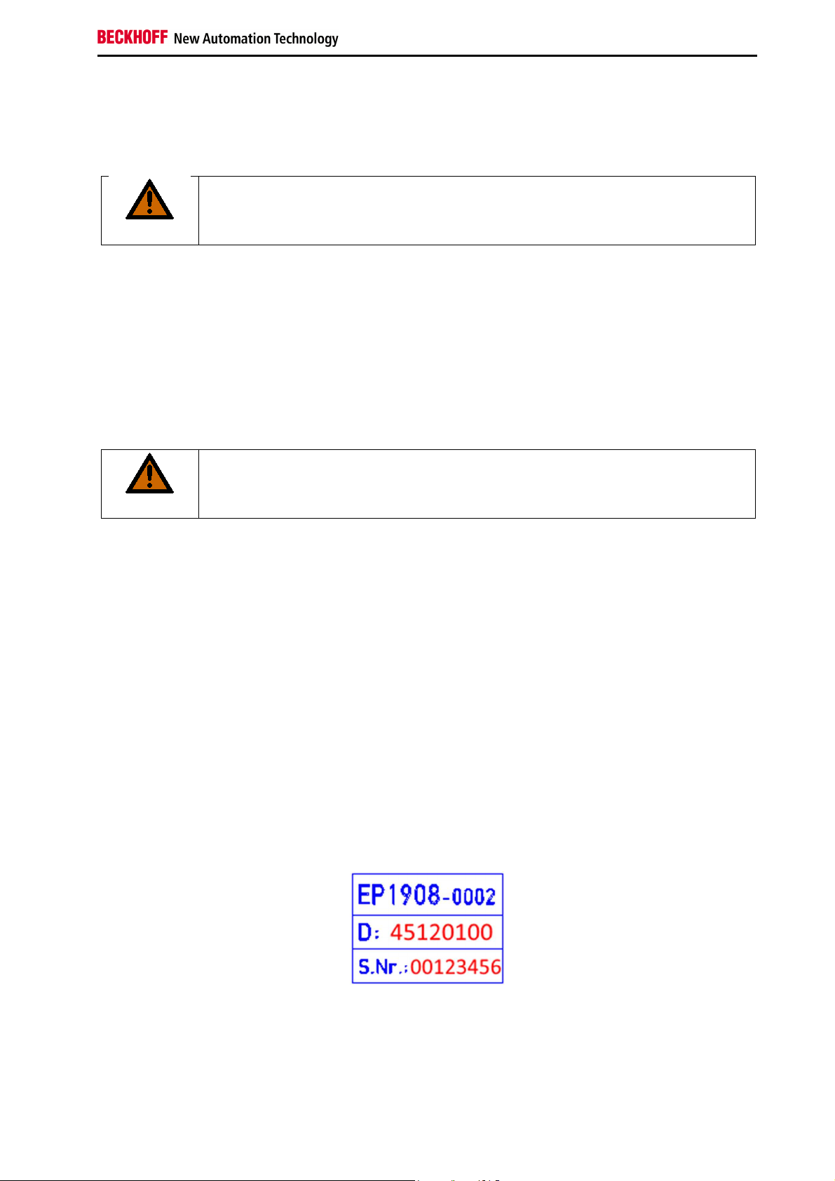
The TwinSAFE EtherCAT Boxes have a date code (D:), which is structured as follows:
Date code: CW YY SW HW
Legend:
CW: Calendar week of manufacture
YY: Year of manufacture
SW: Software version
HW: Hardware version
In addition, the TwinSAFE EtherCAT Boxes have a unique serial number (S.No.:).
Example: Date code 45 12 01 00
Calendar week: 45
Year: 2012
Software version: 01
Hardware version: 00
EP1908-0002 37
Page 40

Operation
4.7 Decommissioning
Serious risk of injury!
DANGER
Bring the bus system into a safe, de-energized state before starting disassembly of the
EtherCAT Boxes!
4.7.1 Disposal
The device must be removed for disposal.
• Housing parts (polyamide PA6-F) are suitable for plastics recycling
• Sealing compound (polyurethane resin)
• Metal parts can be sent for metal recycling.
• Electronic parts such as disk drives and circuit boards must be disposed of in accordance with
national electronics scrap regulations.
38
EP1908-0002
Page 41

Appendix
5 Appendix
5.1 Protection classes according to IP code
Protection classes defining different degrees of protection are specified in IEC 60529 (DIN EN 60529) as
follows:
1st digit: Protection
against ingress of
dust and access to
hazardous parts
0 Non-protected
1
2
3
4
5
6
2nd digit: Protection
against ingress of
water*
0 Non-protected.
1 Protection against dripping water.
2 Protection against dripping water when housing tilted up to 15°.
3
4
5 Protection against jetting.
6 Protection against powerful jetting.
7
*) These protection classes only define protection against water, not against other liquids.
Meaning
Protection against access to hazardous parts with back of hand. Protection
against ingress of solid foreign objects = 50 mm diameter
Protection against access to hazardous parts with a finger. Protection against
ingress of solid foreign objects = 12.5 mm diameter
Protection against access to hazardous parts with a tool. Protection against
ingress of solid foreign objects = 2.5 mm diameter
Protection against access to hazardous parts with a wire. Protection against
ingress of solid foreign objects = 1 mm diameter
Protection against access to hazardous parts with a wire. Protection against
ingress of dust. Ingress of dust is not prevented completely, although the
quantity of dust able to penetrate is limited to such an extent that the proper
function of the device and safety are not impaired
Protection against access to hazardous parts with a wire. Dust-proof. No
ingress of dust
Meaning
Protection against spraying. Water sprayed at an angle of up to 60° from
vertical must not have any adverse effect.
Protection against splashing. Water splashing against the housing from any
direction must not have any adverse effects.
Protection against the effects of temporary immersion. The quantity of water
being able to penetrate if the housing is submerged in water for 30 minutes at
a depth of 1 m must not have any adverse effects.
EP1908-0002 39
Page 42

Appendix
5.1 Beckhoff Support and Service
Beckhoff and their partners around the world offer comprehensive support and service, making available
fast and competent assistance with all questions related to Beckhoff products and system solutions.
5.1.1 Beckhoff branches and partner companies Beckhoff Support
Please contact your Beckhoff branch office or partner company for local support and service on Beckhoff
products!
The contact addresses for your country can be found in the list of Beckhoff branches and partner
companies: www.beckhoff.com. You will also find further documentation for Beckhoff components there.
5.1.2 Beckhoff company headquarters
Beckhoff Automation GmbH & Co.KG
Huelshorstweg 20
33415 Verl
Germany
Phone: + 49 (0) 5246/963-0
Fax: + 49 (0) 5246/963-198
E-mail: info@beckhoff.com
Web: www.beckhoff.com
Beckhoff Support
Support offers you comprehensive technical assistance, helping you not only with the application of
individual Beckhoff products, but also with other, wide-ranging services:
• world-wide support
• design, programming and commissioning of complex automation systems
• and extensive training program for Beckhoff system components
Hotline: + 49 (0) 5246/963-157
Fax: + 49 (0) 5246/963-9157
E-mail: support@beckhoff.com
Beckhoff Service
The Beckhoff Service Center supports you in all matters of after-sales service:
• on-site service
• repair service
• spare parts service
• hotline service
Hotline: + 49 (0) 5246/963-460
Fax: + 49 (0) 5246/963-479
E-mail: service@beckhoff.com
40
EP1908-0002
Page 43

Appendix
5.2 Certificate
EP1908-0002 41
 Loading...