

Page 1
Operating manual | EN
ELX1052, ELX1054 and ELX1058
Two, four and eight channel digital input terminals for NAMUR
sensors, Ex i
2021-01-27 | Version: 2.1.0
Page 2

Page 3

Table of contents
Table of contents
1 Foreword ....................................................................................................................................................5
1.1 Notes on the documentation..............................................................................................................5
1.2 Safety instructions .............................................................................................................................6
1.3 Documentation Issue Status..............................................................................................................7
1.4 Marking of ELX terminals ..................................................................................................................8
2 Product overview.....................................................................................................................................12
2.1 ELX1052 - Introduction....................................................................................................................12
2.2 ELX1054 - Introduction....................................................................................................................13
2.3 ELX1058 - Introduction....................................................................................................................14
2.4 Technical data .................................................................................................................................15
2.5 Intended use....................................................................................................................................16
3 Mounting and wiring................................................................................................................................17
3.1 Special conditions of use for ELX terminals ....................................................................................17
3.2 Installation notes for ELX terminals .................................................................................................17
3.3 Arrangement of ELX terminals within a bus terminal block .............................................................19
3.4 Installation position and minimum distances ...................................................................................22
3.5 Installation of ELX terminals on mounting rails................................................................................23
3.6 Connection ......................................................................................................................................25
3.6.1 Connection system .......................................................................................................... 25
3.6.2 Wiring............................................................................................................................... 26
3.6.3 Proper line connection ..................................................................................................... 27
3.6.4 Shielding and potential separation................................................................................... 27
3.6.5 ELX1052 - Contact assignment ....................................................................................... 28
3.6.6 ELX1054 - Contact assignment ....................................................................................... 29
3.6.7 ELX1058 - Contact assignment ....................................................................................... 31
4 Appendix ..................................................................................................................................................33
4.1 EtherCAT AL Status Codes.............................................................................................................33
4.2 UL notice .........................................................................................................................................33
4.3 FM notice.........................................................................................................................................34
4.4 Support and Service ........................................................................................................................35
ELX1052, ELX1054 and ELX1058 3Version: 2.1.0
Page 4

Table of contents
ELX1052, ELX1054 and ELX10584 Version: 2.1.0
Page 5

Foreword
1 Foreword
1.1 Notes on the documentation
Intended audience
This description is only intended for the use of trained specialists in control and automation engineering who
are familiar with the applicable national standards.
It is essential that the documentation and the following notes and explanations are followed when installing
and commissioning these components.
It is the duty of the technical personnel to use the documentation published at the respective time of each
installation and commissioning.
The responsible staff must ensure that the application or use of the products described satisfy all the
requirements for safety, including all the relevant laws, regulations, guidelines and standards.
Disclaimer
The documentation has been prepared with care. The products described are, however, constantly under
development.
We reserve the right to revise and change the documentation at any time and without prior announcement.
No claims for the modification of products that have already been supplied may be made on the basis of the
data, diagrams and descriptions in this documentation.
Trademarks
Beckhoff®, TwinCAT®, EtherCAT®, EtherCATG®, EtherCATG10®, EtherCATP®, SafetyoverEtherCAT®,
TwinSAFE®, XFC®, XTS® and XPlanar® are registered trademarks of and licensed by Beckhoff Automation
GmbH. Other designations used in this publication may be trademarks whose use by third parties for their
own purposes could violate the rights of the owners.
Patent Pending
The EtherCAT Technology is covered, including but not limited to the following patent applications and
patents: EP1590927, EP1789857, EP1456722, EP2137893, DE102015105702 with corresponding
applications or registrations in various other countries.
EtherCAT® is registered trademark and patented technology, licensed by Beckhoff Automation GmbH,
Germany.
Copyright
© Beckhoff Automation GmbH & Co. KG, Germany.
The reproduction, distribution and utilization of this document as well as the communication of its contents to
others without express authorization are prohibited.
Offenders will be held liable for the payment of damages. All rights reserved in the event of the grant of a
patent, utility model or design.
ELX1052, ELX1054 and ELX1058 5Version: 2.1.0
Page 6
Foreword
1.2 Safety instructions
Safety regulations
Please note the following safety instructions and explanations!
Product-specific safety instructions can be found on following pages or in the areas mounting, wiring,
commissioning etc.
Exclusion of liability
All the components are supplied in particular hardware and software configurations appropriate for the
application. Modifications to hardware or software configurations other than those described in the
documentation are not permitted, and nullify the liability of Beckhoff Automation GmbH & Co. KG.
Personnel qualification
This description is only intended for trained specialists in control, automation and drive engineering who are
familiar with the applicable national standards.
Description of instructions
In this documentation the following instructions are used.
These instructions must be read carefully and followed without fail!
DANGER
Serious risk of injury!
Failure to follow this safety instruction directly endangers the life and health of persons.
WARNING
Risk of injury!
Failure to follow this safety instruction endangers the life and health of persons.
CAUTION
Personal injuries!
Failure to follow this safety instruction can lead to injuries to persons.
NOTE
Damage to environment/equipment or data loss
Failure to follow this instruction can lead to environmental damage, equipment damage or data loss.
Tip or pointer
This symbol indicates information that contributes to better understanding.
ELX1052, ELX1054 and ELX10586 Version: 2.1.0
Page 7

1.3 Documentation Issue Status
Version Comment
2.1.0 • Chapter Operation modes and LED Display for ELX1058 updated
2.0.0 • ELX1058 added
• Technical data updated
• Chapter Wiring updated
• Chapter Marking of ELX terminals updated
• Design of safety instructions adapted to IEC 82079-1.
1.7.0 • FM notice regarding ANSI/ISA EX added
• Chapter Marking of ELX terminals updated
1.6.0 • ELX1054 added
• Technical data updated
1.5.0 • Contact assignment extended with sensor illustration
• Chapter Arrangement of ELX terminals within a bus terminal block updated
• Chapter Wiring updated
• Chapter Marking of ELX terminals updated
• Technical data updated
1.4.0 • Chapter Arrangement of ELX terminals at the bus terminal updated
1.3.0 • Chapter Installation notes for ELX terminals updated
1.2.0 • Chapter Marking of ELX terminals updated
• Technical data updated
1.1.0 • Chapter Marking of ELX terminals updated
1.0.0 • Technical data updated
0.2 • Chapter Marking of ELX-Terminals added
• Technical data updated
• Chapter Intended use added
• Chapter Special conditions for ELX terminals added
• Chapter Installation notes for ELX terminals added
• Chapter Arrangement of ELX terminals at the bus terminal block added
• Chapter Installation position and minimum distances added
• Chapter Installation of ELX terminals on mounting rails updated
• Chapter Mounting and wiring updated
0.1 • First preliminary version
Foreword
ELX1052, ELX1054 and ELX1058 7Version: 2.1.0
Page 8
Foreword
1.4 Marking of ELX terminals
Name
An ELX terminal has a 15-digit technical designation, composed of
• family key
• type
• software variant
• revision
example family type software variant revision
ELX1052-0000-0001 ELX terminal 1052: two-channel digital input terminal
for NAMUR sensors, Ex i
ELX9560-0000-0001 ELX terminal 9560: power supply terminal 0000: basic type 0001
Notes
• The elements mentioned above result in the technical designation. ELX1052-0000-0001 is used in
the example below.
• Of these, ELX1052-0000 is the order identifier, commonly called just ELX1052 in the "-0000" revision.
“-0001” is the EtherCAT revision.
• The order identifier is made up of
- family key (ELX)
- type (1052)
- software version (-0000)
• The Revision -0001 shows the technical progress, such as the extension of features with regard to the
EtherCAT communication, and is managed by Beckhoff.
In principle, a device with a higher revision can replace a device with a lower revision, unless specified
otherwise, e.g. in the documentation.
Associated and synonymous with each revision there is usually a description (ESI, EtherCAT Slave
Information) in the form of an XML file, which is available for download from the Beckhoff website.
The revision has been applied to the terminals on the outside, see ELX1052 with date code
3218FMFM, BTN 10000100 and Ex marking.
• The hyphen is omitted in the labeling on the side of the terminal. Example:
Name: ELX1052-0000
Label: ELX1052
• The type, software version and revision are read as decimal numbers, even if they are technically
saved in hexadecimal.
0000
0000: basic type 0001
Identification numbers
ELX terminals have two different identification numbers:
• date code (batch number)
• Beckhoff Traceability Number, or BTN for short (as a serial number it clearly identifies each terminal)
Datecode
The date code is an eight-digit number given by Beckhoff and printed on the ELX terminal. The date code
indicates the build version in the delivery state and thus identifies an entire production batch, but does not
distinguish between the terminals in a batch.
Structure of the date code: WWYYFFHH
WW - week of production (calendar week)
YY - year of production
FF - firmware version
HH - hardware version
Example with date code: 02180100:
02 - week of production 02
18 - year of production 2018
01 - firmware version 01
00 - hardware version 00
ELX1052, ELX1054 and ELX10588 Version: 2.1.0
Page 9

Beckhoff Traceability Number (BTN)
In addition, each ELX terminal has a unique Beckhoff Traceability Number (BTN).
Ex marking
The Ex marking can be found at the top left on the terminal:
II 3 (1) G Ex ec [ia Ga] IIC T4 Gc
II (1) D [Ex ia Da] IIIC
I (M1) [Ex ia Ma] I
IECEx BVS 18.0005X
BVS 18 ATEX E 005 X
Examples
Foreword
Fig.1: ELX2008-0000 with date code 2519HMHM, BTN 0001f6hd and Ex marking
ELX1052, ELX1054 and ELX1058 9Version: 2.1.0
Page 10
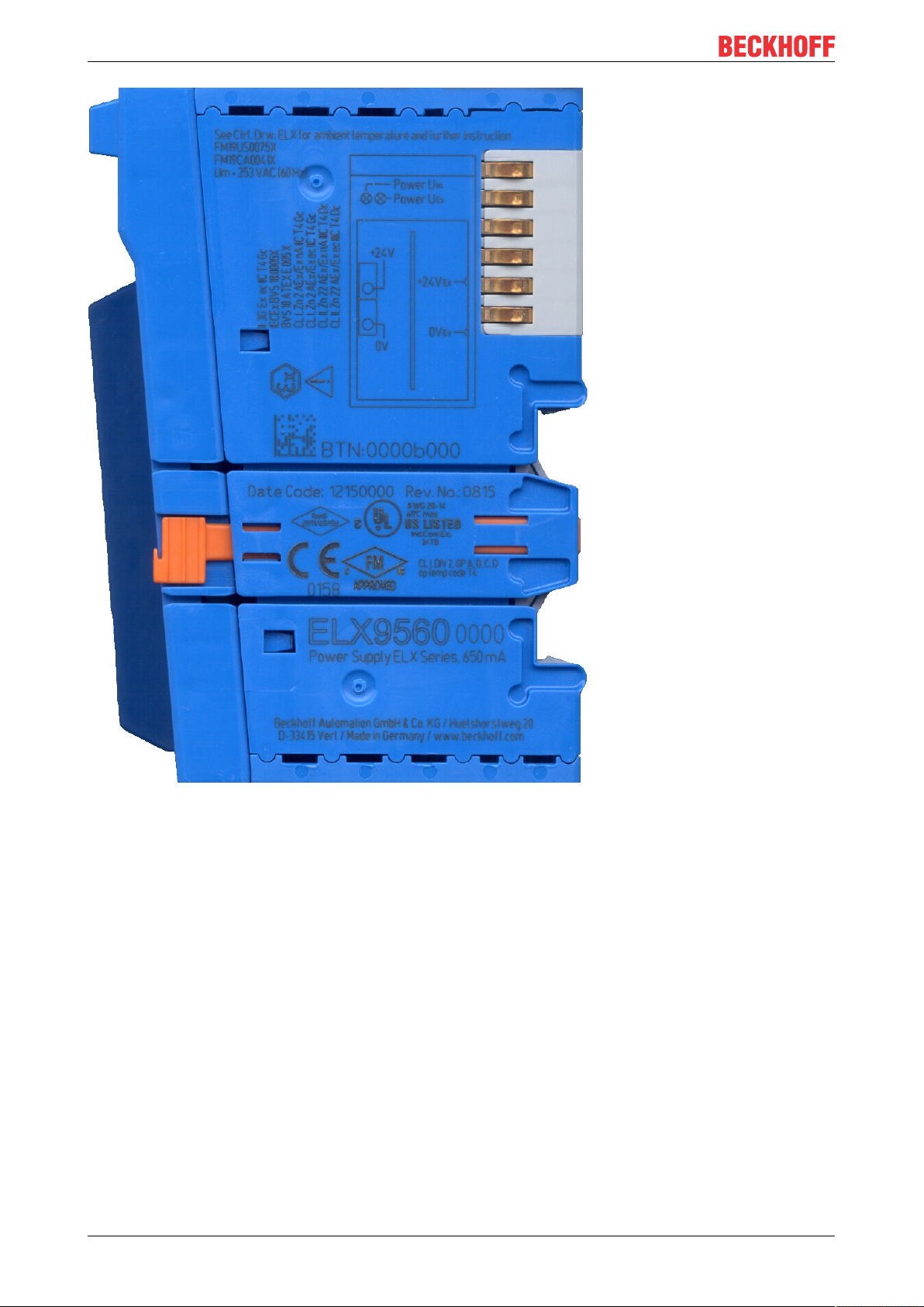
Foreword
Fig.2: ELX9560-0000 with date code 12150000, BTN 000b000 and Ex marking
ELX1052, ELX1054 and ELX105810 Version: 2.1.0
Page 11
Foreword
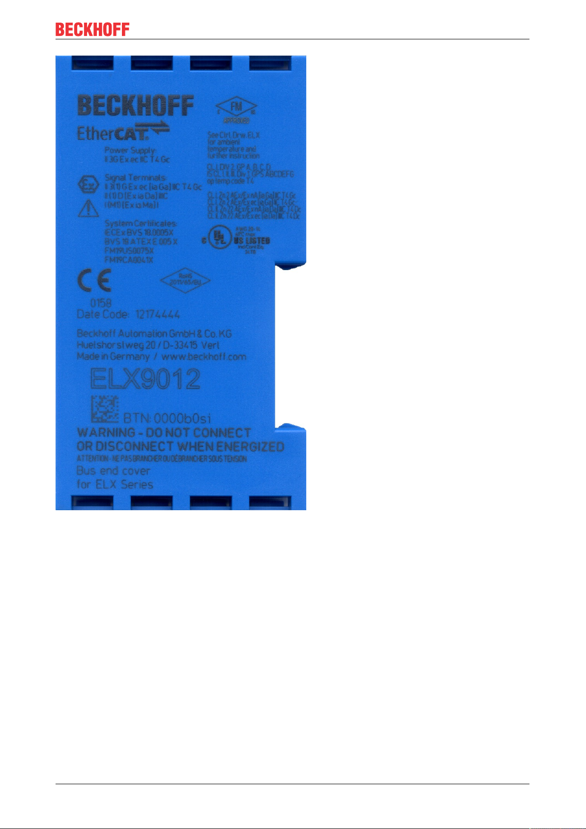
Fig.3: ELX9012 with date code 12174444, BTN 0000b0si and Ex marking
ELX1052, ELX1054 and ELX1058 11Version: 2.1.0
Page 12
Product overview
2 Product overview
2.1 ELX1052 - Introduction
Fig.4: ELX1052 - 2-channel digital input terminal for NAMUR sensors, Exi
The ELX1052 digital input terminal acquires signals from NAMUR field devices according to EN60947-5-6.
The sensors are supplied with a voltage of 8.2V and return a diagnosable current signal. In this way, a wire
breakage or short-circuit can be detected in addition to the switching state. The LEDs indicate signal or any
error states, channel by channel. The sensor supply is equipped with voltage and current limitation for each
channel.
ELX1052, ELX1054 and ELX105812 Version: 2.1.0
Page 13

2.2 ELX1054 - Introduction
Product overview
Fig.5: ELX1054 - 4-channel digital input terminal for NAMUR sensors, Exi
The ELX1054 digital input terminal acquires signals from NAMUR field devices according to EN60947-5-6.
The sensors are supplied with a voltage of 8.2V and return a diagnosable current signal. In this way, a wire
breakage or short-circuit can be detected in addition to the switching state. The LEDs indicate signal or any
error states, channel by channel. The sensor supply is equipped with voltage and current limitation for each
channel.
Using the DIP switch [}30] on the side, it is possible to select channel by channel whether a positive
switching or negative switching sensor is to be connected. Thus, no changes to the PLC are required for the
connection of both NAMUR break contacts or make contacts.
ELX1052, ELX1054 and ELX1058 13Version: 2.1.0
Page 14

Product overview
2.3 ELX1058 - Introduction
Fig.6: ELX1058 - 8-channel digital input terminal for NAMUR sensors, Exi
The ELX1058 digital input terminal allows the direct connection of intrinsically safe NAMUR field devices
from hazardous areas of zones 0/20 and 1/21 and records their signals according to IEC60947-5-6. The
sensors are supplied with a voltage of 8.2V and return a current signal that can be diagnosed. In this way, in
addition to the switching status, line break or short circuit is also detected. The LEDs display the signal or
any error states.
By software, it is possible to select channel by channel whether a positive switching or negative switching
sensor is to be connected. In this way, both NAMUR openers and closers can be integrated into the control
system.
ELX1052, ELX1054 and ELX105814 Version: 2.1.0
Page 15

Product overview
2.4 Technical data
Technical data ELX1052-0000 ELX1054-0000 ELX1058-0000
Technology NAMUR
Number of inputs 2 4 8
Signal type binary/current
Specification NAMUR DC switching amplifier (IEC 60947-5-6)
Connection technology 2-wire
“0“ signal current ≤ 1.2mA
“1“ signal current ≥ 2.1mA
Switching hysteresis typ. 200µA typ. 200µA typ. 300µA
Switching frequency max. 50Hz
(duty cycle 50%)
Open circuit voltage typ. 8.2V
Current limitation > 8.2mA typ. > 7mA typ.
Short circuit detection > 6.3mA typ.
Distributed Clocks -
Supply voltage electronics via E-Bus (5VDC) and Power Contacts (24V
ELX9560)
Current consumption from the E-Bus typ. 50mA typ. 70mA
Current consumption from the Power
Contacts
Electrical isolation 1500V (E-Bus/ field potential)
Bit width in the process image 2 x 2bit 4 x 2 bit + 4 bit input
Weight approx. 45g approx. 50g approx. 65g
Permissible ambient temperature range
during operation
Permissible ambient temperature range
during storage
Permissible relative humidity 95 %, no condensation
Permissible air pressure
(operation, storage, transport)
Dimensions (W x H x D) ca. 15mm x 100mm x 70mm (width aligned: 12 mm)
Mounting on 35 mm mounting rail conforms to EN 60715
Vibration/shock resistance conforms to EN60068-2-6/ EN60068-2-27
EMC immunity/emission conforms to EN61000-6-2/ EN61000-6-4
Protect. class IP20
Permissible installation position
Approvals/ markings CE, UL, ATEX, IECEx, cFMus CE, ATEX, IECEx
typ. 10mA + load typ. 15mA + load
-25°C ... + 60°C
-40°C ... + 85°C
800hPa to 1100hPa
(this corresponds to a height of approx. -690m to 2000m over
sea level assuming an international standard atmosphere)
See chapter Installation position and minimum distances [}22]
max. 5kHz
(duty cycle 50%)
type NC status
max. 5kHz
(duty cycle 50%)
Ex, feeding by
DC
8 x 2bit
ELX1052, ELX1054 and ELX1058 15Version: 2.1.0
Page 16

Product overview
Technical data for explosion protection ELX1052-0000 ELX1054-0000
ELX1058-0000
Ex marking II 3 (1) G Ex ec [ia Ga] IIC T4 Gc
II (1) D [Ex ia Da] IIIC
I (M1) [Ex ia Ma] I
Certificate numbers IECEx BVS 18.0005X
BVS 18 ATEX E 005 X
Power supply Invariable in connection with ELX9560
Field interfaces UO = 10.75V
IO = 12.0mA
PO = 33mW
linear
Reactance
(without consideration of the
simultaneousness)
Ex ia I 100mH 58µF 100mH 58µF
Ex ia IIA 100mH 66µF 100mH 66µF
L
0
C
0
UO = 10.72V
IO = 10.4mA
PO = 28mW
linear
L
0
Ex ia IIB 100mH 15µF 100mH 15µF
Ex ia IIC 100mH 2.14µF 100mH 2.14µF
Ex ia IIIC 100mH 15µF 100mH 15µF
C
0
2.5 Intended use
WARNING
Endangering the safety of persons and equipment!
The ELX components may only be used for the purposes described below!
CAUTION
Observe ATEX and IECEx!
The ELX components may only be used in accordance with the ATEX directive and the IECEx scheme!
The ELX terminals extend the field of application of the Beckhoff bus terminal system with functions for
integrating intrinsically safe field devices from hazardous areas. The intended field of application is data
acquisition and control tasks in discrete and process engineering automation, taking into account explosion
protection requirements.
The ELX terminals are protected by the type of protection "Increased safety" (Exe) according to
IEC60079-7 and must only be operated in hazardous areas of Zone2 or in non-hazardous areas.
The field interfaces of the ELX terminals achieve explosion protection through the type of protection "intrinsic
safety" (Exi) according to IEC60079-11. For this reason, only appropriately certified, intrinsically safe
devices may be connected to the ELX terminals. Observe the maximum permissible connection values for
voltages, currents and reactances. Any infringement can damage the ELX terminals and thus eliminate the
explosion protection.
The ELX terminals are open, electrical equipment for installation in lockable cabinets, enclosures or
operating rooms. Make sure that access to the equipment is only possible for authorized personnel.
CAUTION
Ensure traceability!
The buyer has to ensure the traceability of the device via the Beckhoff Traceability Number (BTN).
ELX1052, ELX1054 and ELX105816 Version: 2.1.0
Page 17

Mounting and wiring
3 Mounting and wiring
3.1 Special conditions of use for ELX terminals
WARNING
Observe the special conditions of use for the intended use of Beckhoff ELX terminals in
potentially explosive areas (ATEX directive 2014/34/EU)!
• The certified components are to be installed in a suitable housing that guarantees an ingress protection
of at least IP54 in accordance with EN60079-0 and EN60529! The prescribed environmental conditions
during installation, operation and maintenance are thereby to be taken into account! Inside the housing,
pollution degree 1 and 2 are permissible.
• If the temperatures during rated operation are higher than 70°C at the feed-in points of cables, lines or
pipes, or higher than 80°C at the wire branching points, then cables must be selected whose temperature data correspond to the actual measured temperature values!
• Observe the permissible ambient temperature range of -25 to +60°C of Beckhoff ELX terminals!
• Measures must be taken to protect against the rated operating voltage being exceeded by more than
40% due to short-term interference voltages! The power supply of the ELX9560 power supply terminal
must correspond to overvoltage categoryII according to EN60664-1
• The individual terminals may only be unplugged or removed from the bus terminal system if all supply
voltages have been switched off or if a non-explosive atmosphere is ensured!
• The connections of the ELX9560 power supply terminal may only be connected or disconnected if all
supply voltages have been switched off or if a non-explosive atmosphere is ensured!
• The fuses of the EL92xx power feed terminals may only be exchanged if all supply voltages have been
switched off or if a non-explosive atmosphere is ensured!
• Address selectors and switches may only be adjusted if all supply voltages have been switched off or if a
non-explosive atmosphere is ensured!
3.2 Installation notes for ELX terminals
NOTE
Storage, transport and mounting
• Transport and storage are permitted only in the original packaging!
• Store in a dry place, free from vibrations.
• A brand new ELX terminal with a certified build version is delivered only in a sealed carton. Therefore,
check that the carton and all seals are intact before unpacking.
• Do not use the ELX terminal if
- its packaging is damaged
- the terminal is visibly damaged or
- you cannot be sure of the origin of the terminal.
• ELX terminals with a damaged packaging seal are regarded as used.
WARNING
Observe the accident prevention regulations
During mounting, commissioning, operation and maintenance, adhere to the safety regulations, accident
prevention regulations and general technical rules applicable to your devices, machines and plants.
CAUTION
Observe the erection regulations
Observe the applicable erection regulations.
ELX1052, ELX1054 and ELX1058 17Version: 2.1.0
Page 18

Mounting and wiring
NOTE
Protect the terminals against electrostatic discharge (ESD)
Electronic components can be destroyed by electrostatic discharge. Therefore, take the safety measures to
protect against electrostatic discharge as described in DIN EN 61340-5-1 among others. In conjunction with
this, ensure that the personnel and surroundings are suitably earthed.
NOTE
Do not place terminals on E-bus contacts
Do not place the ELX terminals on the E-bus contacts located on the right-hand side. The function of the Ebus contacts can be negatively affected by damage caused by this, e.g. scratches.
NOTE
Protect the terminals against dirt
To ensure the functionality of the ELX terminals they must be protected against dirt, especially on the contact points. For this reason use only clean tools and materials.
NOTE
Handling
• It is forbidden to insert conductive or non-conductive objects of any kind into the interior of the housing
(e.g. through the ventilation slots in the housing).
• Use only the openings provided in the housing front and appropriate tools to actuate the spring-loaded
terminal contacts on the front side for attaching connection cables to the terminal; see chapter Wiring
[}26].
• The opening of the housing, the removal of parts and any mechanical deformation or machining of an
ELX terminal are not permitted!
If an ELX terminal is defective or damaged it must be replaced by an equivalent terminal. Do not carry out
any repairs to the devices. For safety reasons repairs may only be carried out by the manufacturer.
NOTE
Contact marking and pin assignment
The colored inscription labels above the front connection contacts shown in the illustrations in the introduction chapter are only examples and are not part of the scope of delivery!
A clear assignment of channel and terminal designation according to the chapter contact assignment to the
actual terminal point can be made via the lasered channel numbers 1 to 8 on the left above the respective
terminal point as well as via the laser image.
Observe any possible polarity dependency of connected intrinsically safe circuits!
ELX1052, ELX1054 and ELX105818 Version: 2.1.0
Page 19

Mounting and wiring
3.3 Arrangement of ELX terminals within a bus terminal block
WARNING
Observe the following instructions for the arrangement of ELX terminals!
• ELX signal terminals must always be installed behind an ELX9560 power supply terminal, without exception!
• Only signal terminals of the ELX series may be installed behind an ELX9560 power supply terminal!
• Multiple ELX9560 power supply terminals may be set in one terminal block as long as one ELX9410 is
placed before each additional ELX9560!
• An ELX9410 power supply terminal must not be mounted to the right of an ELX9560 nor to the left of any
ELX signal terminal!
• The last terminal of each ELX segment is to be covered by an ELX9012 bus end cover, unless two
ELX9410 power supply terminals are installed in direct succession for continuing the same terminal segment with standard Beckhoff EtherCAT terminals (e.g. EL/ES/EK)!
Examples for the arrangement of ELX terminals
Fig.7: Valid arrangement of the ELX terminals (right terminal block).
Fig.8: Valid arrangement - terminals that do not belong to the ELX series are set before and after the ELX
terminal segment. The separation is realized by the ELX9560 at the beginning of the ELX terminal segment
and two ELX9410 at the end of the ELX terminal segment.
Fig.9: Valid arrangement - multiple power supplies by ELX9560, each with an upstream ELX9410.
ELX1052, ELX1054 and ELX1058 19Version: 2.1.0
Page 20

Mounting and wiring
Fig.10: Valid arrangement - ELX9410 in front of an ELX9560 power supply terminal.
Fig.11: Invalid arrangement - missing ELX9560 power supply terminal.
Fig.12: Invalid arrangement - terminal that does not belong to the ELX series within the ELX terminal
segment.
Fig.13: Invalid arrangement - second ELX9560 power supply terminal within the ELX terminal segment
without an upstream ELX9410.
ELX1052, ELX1054 and ELX105820 Version: 2.1.0
Page 21

Mounting and wiring
Fig.14: Invalid arrangement - missing ELX9012 bus end cover.
NOTE
Observe the maximum output current of the ELX9560
When configuring the ELX terminal segment, please note the maximum available output current of the
ELX9560 power supply terminal in accordance with the specified technical data.
If required, an additional power supply terminal ELX9560 with an upstream ELX9410 connected (see
mounting examples) must be installed or a completely new terminal block must be assembled.
ELX1052, ELX1054 and ELX1058 21Version: 2.1.0
Page 22

Mounting and wiring
3.4 Installation position and minimum distances
Installation position
For the prescribed installation position the mounting rail is installed horizontally and the mating surfaces of
the ELX terminals point toward the front (see illustration below). The terminals are ventilated from below,
which enables optimum cooling of the electronics through convection. The direction indication “down”
corresponds to the direction of positive acceleration due to gravity.
Minimum distances
Observe the following minimum distances to ensure optimum convection cooling:
• above and below the ELX terminals: 35mm (required!)
• besides the bus terminal block: 20mm (recommended)
Fig.15: Installation position and minimum distances
WARNING
Observe the minimum separation distances according to IEC 60079-14!
Observe the prescribed minimum separation distances between intrinsically safe and non-intrinsically safe
circuits according to IEC 60079-14.
ELX1052, ELX1054 and ELX105822 Version: 2.1.0
Page 23

Mounting and wiring
3.5 Installation of ELX terminals on mounting rails
WARNING
Risk of electric shock and damage of device!
Bring the bus terminal system into a safe, powered down state before starting installation, disassembly or
wiring of the bus terminals!
CAUTION
Danger of injury due to power contacts!
For your own protection, pay attention to careful and careful handling of the ELX terminals. In particular, the
left side mounted, sharp-edged blade contacts pose a potential risk of injury.
Assembly
Fig.16: Attaching on mounting rail
The bus coupler and bus terminals are attached to commercially available 35mm mounting rails (DIN rails
according to EN60715) by applying slight pressure:
1. First attach the fieldbus coupler to the mounting rail.
2. The bus terminals are now attached on the right-hand side of the fieldbus coupler. Join the components with tongue and groove and push the terminals against the mounting rail, until the lock clicks
onto the mounting rail.
If the terminals are clipped onto the mounting rail first and then pushed together without tongue and
groove, the connection will not be operational! When correctly assembled, no significant gap should
be visible between the housings.
Fixing of mounting rails
The locking mechanism of the terminals and couplers extends to the profile of the mounting rail. At
the installation, the locking mechanism of the components must not come into conflict with the fixing
bolts of the mounting rail. To mount the mounting rails with a height of 7.5mm under the terminals
and couplers, you should use flat mounting connections (e.g. countersunk screws or blind rivets).
ELX1052, ELX1054 and ELX1058 23Version: 2.1.0
Page 24

Mounting and wiring
Disassembly
Fig.17: Disassembling of terminal
Each terminal is secured by a lock on the mounting rail, which must be released for disassembly:
1. Pull the terminal by its orange-colored lugs approximately 1cm away from the mounting rail. In doing
so for this terminal the mounting rail lock is released automatically and you can pull the terminal out of
the bus terminal block easily without excessive force.
2. Grasp the released terminal with thumb and index finger simultaneous at the upper and lower grooved
housing surfaces and pull the terminal out of the bus terminal block.
Connections within a bus terminal block
The electric connections between the Bus Coupler and the Bus Terminals are automatically realized by
joining the components:
• The six spring contacts of the E-Bus deal with the transfer of the data and the supply of the Bus
Terminal electronics.
• The power contacts deal with the supply for the field electronics and thus represent a supply rail within
the bus terminal block.
The power contacts of the ELX terminals are supplied by the ELX9560 power terminal. This interrupts
the power contacts and thus represents the beginning of a new supply rail.
Power Contacts
During the design of a bus terminal block, the pin assignment of the individual Bus Terminals must
be taken account of, since some types (e.g. analog Bus Terminals or digital 4-channel Bus Terminals) do not or not fully loop through the power contacts.
ELX1052, ELX1054 and ELX105824 Version: 2.1.0
Page 25

Mounting and wiring
3.6 Connection
3.6.1 Connection system
WARNING
Risk of electric shock and damage of device!
Bring the bus terminal system into a safe, powered down state before starting installation, disassembly or
wiring of the bus terminals!
The terminals of ELXxxxx series include electronics and connection level in a single enclosure.
Standard wiring
Fig.18: Standard wiring
The terminals of ELXxxxx series feature integrated screwless spring force technology for fast and simple
assembly.
High Density Terminals (HD Terminals)
Fig.19: High Density Terminals
The Bus Terminals from these series with 16 connection points are distinguished by a particularly compact
design, as the packaging density is twice as large as that of the standard 12mm Bus Terminals. Massive
conductors and conductors with a wire end sleeve can be inserted directly into the spring loaded terminal
point without tools.
Ultrasonically "bonded" (ultrasonically welded) conductors
Ultrasonically “bonded" conductors
It is also possible to connect the Standard and High Density Terminals with ultrasonically
"bonded" (ultrasonically welded) conductors. In this case, please note the tables concerning the
wire-size width below!
ELX1052, ELX1054 and ELX1058 25Version: 2.1.0
Page 26

Mounting and wiring
3.6.2 Wiring
WARNING
Risk of electric shock and damage of device!
Bring the bus terminal system into a safe, powered down state before starting installation, disassembly or
wiring of the bus terminals!
Terminals for standard wiring
Fig.20: Connecting a cable on a terminal point
Up to eight terminal points enable the connection of solid or finely stranded cables to the Bus Terminal. The
terminal points are implemented in spring force technology. Connect the cables as follows:
1. Open a terminal point by pushing a screwdriver straight against the stop into the square opening
above the terminal point. Do not turn the screwdriver or move it alternately (don't toggle).
2. The wire can now be inserted into the round terminal opening without any force.
3. The terminal point closes automatically when the pressure is released, holding the wire securely and
permanently.
Observe the requirements for connecting cables and cross sections according to IEC 60079-7 and IEC
60079-11. See the following tables for the suitable wire size width.
Terminal housing Standard wiring ELX9560
Wire size width (single core wires) 0.08 ... 2.5mm
Wire size width (fine-wire conductors) 0.08 ... 2.5mm
Wire size width (conductors with a wire end sleeve) 0.14 ... 1.5mm
2
2
2
0.14 ... 1.5mm
0.14 ... 1.5mm
0.14 ... 1.0mm
2
2
2
Wire stripping length 8 ... 9mm 8 ... 9mm
NOTE
Maximum screwdriver width for ELX9560
Use a screwdriver with a maximum width of 2mm to wire the ELX9560 power supply terminal. Wider
screwdrivers can damage the terminal points.
ELX1052, ELX1054 and ELX105826 Version: 2.1.0
Page 27

Mounting and wiring
High Density Terminals (HD Terminals) with 16 terminal points
The conductors of the HD Terminals are connected without tools for single-wire conductors using the direct
plug-in technique, i.e. after stripping the wire is simply plugged into the terminal point. The cables are
released, as usual, using the contact release with the aid of a screwdriver. See the following table for the
suitable wire size width.
Terminal housing High Density Housing
Wire size width (single core wires) 0.08 ... 1.5mm
Wire size width (fine-wire conductors) 0.25 ... 1.5mm
Wire size width (conductors with a wire end sleeve) 0.14 ... 0.75mm
Wire size width (ultrasonically “bonded" conductors) only 1.5mm
2
2
2
2
Wire stripping length 8 ... 9mm
3.6.3 Proper line connection
Always connect only one wire per terminal point.
When using fine-wire conductors it is recommended to connect them with wire end sleeves in order to
establish a safe, conductive connection.
In addition, make sure that the pin assignment is correct to prevent damage to the ELX terminals and the
connected devices.
3.6.4 Shielding and potential separation
Shielding
Encoder, analog sensors and actors should always be connected with shielded, twisted paired
wires.
CAUTION
Observe installation requirements in areas of potentially explosive atmospheres!
During installation, observe the requirements for cables, shielding and earth potential equalization in areas
of potentially explosive atmospheres according to IEC60079-11, IEC60079-14 and IEC60079-25.
WARNING
Ensure potential separation of the 24V Ex busbar!
In any case, make sure that the galvanic isolation made by the ELX9560 between the 24V Ex busbar
(power contacts +24VEx and 0VEx) and other system potentials (if applicable also functional or protective earths) is not removed.
ELX1052, ELX1054 and ELX1058 27Version: 2.1.0
Page 28

Mounting and wiring
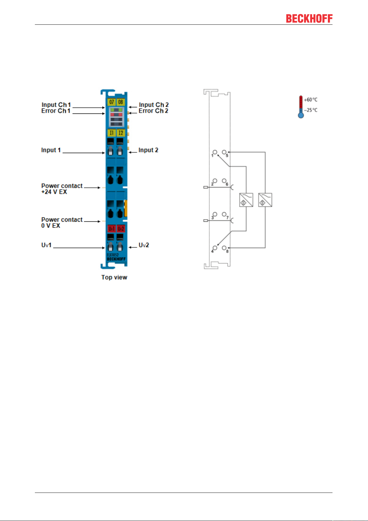
3.6.5 ELX1052 - Contact assignment
Fig.21: ELX1052 - Contact assignment
Terminal point Description
Designation No.
Input 1 1 Input Channel 1
2 not implemented
3 not implemented
Uv1 4 Sensor supply Channel 1
Input 2 5 Input Channel 2
6 not implemented
7 not implemented
Uv2 8 Sensor supply Channel 2
LED Display
The following table is assigned to the respective LED number of a channel.
Input LED Error LED Meaning
off on Error detection: open- circuit on channel (I < 200µA typ.)
off off Usual operation: NAMUR sensor on channel in non-conductive state
("0"; according to IEC 60947-5-6)
on on Error detection: short-circuit on channel (I > 6.3mA typ.)
on off Usual operation: NAMUR sensor on channel in conducting state
("1"; according to IEC60947-5-6)
ELX1052, ELX1054 and ELX105828 Version: 2.1.0
Page 29

3.6.6 ELX1054 - Contact assignment
Mounting and wiring
Fig.22: ELX1054 - Contact assignment
Terminal point Description
Designation No.
Input 1 1 Input Channel 1
Uv1 2 Sensor supply Channel 1
Uv3 3 Sensor supply Channel 3
Input 3 4 Input Channel 3
Input 2 5 Input Channel 2
Uv2 6 Sensor supply Channel 2
Uv4 7 Sensor supply Channel 4
Input 4 8 Input Channel 4
ELX1052, ELX1054 and ELX1058 29Version: 2.1.0
Page 30

Mounting and wiring
DIP switch
The DIP switch allows to invert the input signal for each channel of the ELX1054 separately. For the
inversion of the signal, the DIP switch must be set to the ON position.
Fig.23: ELX1054 - DIP switch
Switch position for sensor
ON negative switching
OFF positive switching (default)
LED display
The following tables are assigned to the respective LED number of a channel.
LED display if DIP switch of the associated channel is in position OFF (default):
Input LED Error LED Meaning
off on Error detection: open- circuit on channel (I < 200µA typ.)
off off Usual operation: NAMUR sensor on channel in non-conductive state
("0"; according to IEC 60947-5-6)
on on Error detection: short-circuit on channel (I > 6.3mA typ.)
on off Usual operation: NAMUR sensor on channel in conducting state
("1"; according to IEC60947-5-6)
LED display if DIP switch of the associated channel is in position ON:
Input LED Error LED Meaning
off on Error detection: short-circuit on channel (I > 6.3mA typ.)
off off Usual operation: NAMUR sensor on channel in conducting state
("1"; according to IEC60947-5-6)
on on Error detection: open- circuit on channel (I < 200µA typ.)
on off Usual operation: NAMUR sensor on channel in non-conductive state
("0"; according to IEC 60947-5-6)
ELX1052, ELX1054 and ELX105830 Version: 2.1.0
Page 31

3.6.7 ELX1058 - Contact assignment
Mounting and wiring
Fig.24: ELX1058 - Contact assignment
Terminal point Description
Designation No.
Input 1 1 Input channel 1
Input 2 2 Input channel 2
Input 3 3 Input channel 3
Input 4 4 Input channel 4
Input 5 5 Input channel 5
Input 6 6 Input channel 6
Input 7 7 Input channel 7
Input 8 8 Input channel 8
Uv1 9 Sensor supply channel 1
Uv2 10 Sensor supply channel 2
Uv3 11 Sensor supply channel 3
Uv4 12 Sensor supply channel 4
Uv5 13 Sensor supply channel 5
Uv6 14 Sensor supply channel 6
Uv7 15 Sensor supply channel 7
Uv8 16 Sensor supply channel 8
ELX1052, ELX1054 and ELX1058 31Version: 2.1.0
Page 32

Mounting and wiring
Operation modes and LED display
The ELX1058 has four operating modes that can be selected channel by channel in the CoE via the Input
Type object (Index 0x80nD:11). In addition, individual channels can be switched off (Channel disabled).
Index 80nD DI Settings (for 0 ≤ n 0 ≤ 7)
Index (hex) Name Meaning Data type Flags Default
80nD:0 DI Settings Maximum subindex UINT8 RW 0x11 (17
80nD:11 Input Type 0x00: Channel disabled
INT16 RW 0x14 (20
0x0A: Dry Contact NO (normally open)
0x0B: Dry Contact NC (normally closed)
0x14: NAMUR NO (normally open)
0x15: NAMUR NC (normally closed)
The ELX1058 has a signal LED for each channel, combining a green input LED with a red error LED. When
both LEDs are on, the result is an orange color - in this case both the input and the error LED are "on". The
following tables are assigned to the respective LED number of a channel.
Operation mode NAMUR NO (normally open, default)
Input Error Meaning
off on Error detection: open-circuit on channel (I < 200µA typ.)
off off Usual operation: NAMUR sensor on channel in non-conductive state
("0"; according to IEC60947-5-6)
on on Error detection: short-circuit on channel (I > 6.3mA typ.)
on off Usual operation: NAMUR sensor on channel in conducting state
("1"; according to IEC60947-5-6)
dez
dez
)
)
Operation mode NAMUR NC (normally closed)
Input Error Meaning
off on Error detection: short circuit at the channel (I > 6.3 mA typ.)
off off Usual operation: NAMUR sensor on channel in conductive state
("1"; according to IEC60947-5-6)
on on Error detection open-circuit on channel (I < 200 μA typ.)
on off Usual operation: NAMUR sensor on channel in non-conductive state
("0"; according to IEC60947-5-6)
No open-circuit and short-circuit detection for Dry Contact NO and Dry Contact NC
In the following operating modes Dry Contact NO and Dry Contact NC, the open-circuit and shortcircuit detection is switched off, so that error bits and error LEDs are always "off".
Operation mode Dry Contact NO (normally open)
Input Error Meaning
off off Sensor on channel in non-conductive state
on off Sensor on channel in conductive state
Operation mode Dry Contact NC (normally closed)
Input Error Meaning
off off Sensor on channel in conductive state
on off Sensor on channel in non-conductive state
In addition to the channel-related LEDs, the ELX1058 also has a general error LED, which indicates an error
in the power supply (24V). This LED is located at the top right of the LED prism.
ELX1052, ELX1054 and ELX105832 Version: 2.1.0
Page 33

4 Appendix
4.1 EtherCAT AL Status Codes
For detailed information please refer to the EtherCAT system description.
4.2 UL notice
Application
Beckhoff EtherCAT modules are intended for use with Beckhoff’s UL Listed EtherCAT System only.
Examination
For cULus examination, the Beckhoff I/O System has only been investigated for risk of fire
and electrical shock (in accordance with UL508 and CSAC22.2 No.142).
For devices with Ethernet connectors
Not for connection to telecommunication circuits.
Appendix
Basic principles
Two UL certificates are met in the Beckhoff EtherCAT product range, depending upon the components:
1. UL certification according to UL508. Devices with this kind of certification are marked by this sign:
2. UL certification according to UL508 with limited power consumption. The current consumed by the device is limited to a max. possible current consumption of 4A. Devices with this kind of certification are
marked by this sign:
Almost all current EtherCAT products (as at 2010/05) are UL certified without restrictions.
Application
If terminals certified with restrictions are used, then the current consumption at 24VDC must be limited
accordingly by means of supply
• from an isolated source protected by a fuse of max. 4A (according to UL248) or
• from a voltage supply complying with NECclass2.
A voltage source complying with NECclass2 may not be connected in series or parallel with another
NECclass2compliant voltage supply!
These requirements apply to the supply of all EtherCAT bus couplers, power adaptor terminals, Bus
Terminals and their power contacts.
ELX1052, ELX1054 and ELX1058 33Version: 2.1.0
Page 34

Appendix
4.3 FM notice
Special notice regarding ANSI/ISA Ex
WARNING
Observe the permissible range of application!
The I/O modules of the ELX series may only be used in potentially explosive areas of ClassI, Division2,
GroupA, B, C, D or in non-explosive areas!
WARNING
Consider the Control Drawing ELX documentation!
When installing the I/O modules of the ELX series, be sure to read the Control Drawing
ELXdocumentation, which is available for download on https://www.beckhoff.de/english/
download/ethercat.htm!
ELX1052, ELX1054 and ELX105834 Version: 2.1.0
Page 35

Appendix
4.4 Support and Service
Beckhoff and their partners around the world offer comprehensive support and service, making available fast
and competent assistance with all questions related to Beckhoff products and system solutions.
Beckhoff's branch offices and representatives
Please contact your Beckhoff branch office or representative for local support and service on Beckhoff
products!
The addresses of Beckhoff's branch offices and representatives round the world can be found on her internet
pages: https://www.beckhoff.com
You will also find further documentation for Beckhoff components there.
Beckhoff Support
Support offers you comprehensive technical assistance, helping you not only with the application of
individual Beckhoff products, but also with other, wide-ranging services:
• support
• design, programming and commissioning of complex automation systems
• and extensive training program for Beckhoff system components
Hotline: +49 5246 963 157
Fax: +49 5246 963 9157
e-mail: support@beckhoff.com
Beckhoff Service
The Beckhoff Service Center supports you in all matters of after-sales service:
• on-site service
• repair service
• spare parts service
• hotline service
Hotline: +49 5246 963 460
Fax: +49 5246 963 479
e-mail: service@beckhoff.com
Beckhoff Headquarters
Beckhoff Automation GmbH & Co. KG
Huelshorstweg 20
33415 Verl
Germany
Phone: +49 5246 963 0
Fax: +49 5246 963 198
e-mail: info@beckhoff.com
web:
ELX1052, ELX1054 and ELX1058 35Version: 2.1.0
https://www.beckhoff.com
Page 36

Table of figures
Table of figures
Fig. 1 ELX2008-0000 with date code 2519HMHM, BTN 0001f6hd and Ex marking ............................. 9
Fig. 2 ELX9560-0000 with date code 12150000, BTN 000b000 and Ex marking ................................. 10
Fig. 3 ELX9012 with date code 12174444, BTN 0000b0si and Ex marking.......................................... 11
Fig. 4 ELX1052 - 2-channel digital input terminal for NAMUR sensors, Exi ......................................... 12
Fig. 5 ELX1054 - 4-channel digital input terminal for NAMUR sensors, Exi ......................................... 13
Fig. 6 ELX1058 - 8-channel digital input terminal for NAMUR sensors, Exi ......................................... 14
Fig. 7 Valid arrangement of the ELX terminals (right terminal block). ................................................... 19
Fig. 8 Valid arrangement - terminals that do not belong to the ELX series are set before and after the
ELX terminal segment. The separation is realized by the ELX9560 at the beginning of the ELX
terminal segment and two ELX9410 at the end of the ELX terminal segment. ........................... 19
Fig. 9 Valid arrangement - multiple power supplies by ELX9560, each with an upstream ELX9410. ... 19
Fig. 10 Valid arrangement - ELX9410 in front of an ELX9560 power supply terminal............................. 20
Fig. 11 Invalid arrangement - missing ELX9560 power supply terminal.................................................. 20
Fig. 12 Invalid arrangement - terminal that does not belong to the ELX series within the ELX terminal
segment. ...................................................................................................................................... 20
Fig. 13 Invalid arrangement - second ELX9560 power supply terminal within the ELX terminal seg-
ment without an upstream ELX9410............................................................................................ 20
Fig. 14 Invalid arrangement - missing ELX9012 bus end cover. ............................................................. 21
Fig. 15 Installation position and minimum distances ............................................................................... 22
Fig. 16 Attaching on mounting rail ........................................................................................................... 23
Fig. 17 Disassembling of terminal............................................................................................................ 24
Fig. 18 Standard wiring............................................................................................................................ 25
Fig. 19 High Density Terminals................................................................................................................ 25
Fig. 20 Connecting a cable on a terminal point ....................................................................................... 26
Fig. 21 ELX1052 - Contact assignment ................................................................................................... 28
Fig. 22 ELX1054 - Contact assignment ................................................................................................... 29
Fig. 23 ELX1054 - DIP switch.................................................................................................................. 30
Fig. 24 ELX1058 - Contact assignment ................................................................................................... 31
ELX1052, ELX1054 and ELX105836 Version: 2.1.0
Page 37

Page 38

More Information:
www.beckhoff.com/elx
Beckhoff Automation GmbH & Co. KG
Hülshorstweg 20
33415 Verl
Germany
Phone: +49 5246 9630
info@beckhoff.com
www.beckhoff.com
 Loading...