

Page 1
Documentation | EN
EL6751
Master/Slave Terminal for CANopen
2021-02-11 | Version: 3.7
Page 2

Page 3

Table of contents
Table of contents
1 Foreword ....................................................................................................................................................5
1.1 Notes on the documentation..............................................................................................................5
1.2 Safety instructions .............................................................................................................................6
1.3 Documentation issue status ..............................................................................................................7
1.4 Version identification of EtherCAT devices .......................................................................................8
1.4.1 Beckhoff Identification Code (BIC)................................................................................... 12
2 Product overview.....................................................................................................................................14
2.1 Introduction......................................................................................................................................14
2.2 Technical data .................................................................................................................................15
2.3 CANopen Introduction .....................................................................................................................16
3 Mounting and wiring................................................................................................................................18
3.1 Recommended mounting rails.........................................................................................................18
3.2 Mounting and demounting - terminals with traction lever unlocking ................................................18
3.3 Mounting and demounting - terminals with front unlocking .............................................................20
3.4 Installation positions ........................................................................................................................22
3.5 Positioning of passive Terminals .....................................................................................................23
3.6 ATEX - Special conditions (extended temperature range) ..............................................................25
3.7 Continuative documentation about explosion protection .................................................................26
3.8 UL notice .........................................................................................................................................26
3.9 CANopen cabling.............................................................................................................................27
3.9.1 CAN topology................................................................................................................... 27
3.9.2 Bus length........................................................................................................................ 27
3.9.3 Drop lines......................................................................................................................... 28
3.9.4 Star Hub (Multiport Tap) .................................................................................................. 28
3.9.5 CAN cable........................................................................................................................ 28
3.9.6 Shielding .......................................................................................................................... 30
3.9.7 Cable colors..................................................................................................................... 30
3.9.8 BK5151, FC51xx, CX with CAN interface and EL6751: D-sub, 9pin .............................. 31
3.9.9 BK51x0/BX5100: 5-pin open style connector .................................................................. 32
3.9.10 LC5100: Bus connection via spring-loaded terminals...................................................... 32
3.9.11 Fieldbus Box: M12 CAN socket ....................................................................................... 33
4 Basics communication ...........................................................................................................................34
4.1 EtherCAT basics..............................................................................................................................34
4.2 EtherCAT State Machine.................................................................................................................34
4.3 General notes for setting the watchdog...........................................................................................35
4.4 CoE Interface...................................................................................................................................37
5 Parameterization and commissioning...................................................................................................42
5.1 TwinCAT Development Environment ..............................................................................................42
5.1.1 Installation of the TwinCAT real-time driver..................................................................... 42
5.1.2 Notes regarding ESI device description........................................................................... 48
5.1.3 OFFLINE configuration creation ...................................................................................... 52
5.1.4 ONLINE configuration creation ........................................................................................ 57
5.1.5 EtherCAT slave process data settings............................................................................. 65
EL6751 3Version: 3.7
Page 4

Table of contents
5.2 General Notes - EtherCAT Slave Application..................................................................................66
5.3 TwinCAT (2.1x) System Manager ...................................................................................................75
5.3.1 Configuration by means of the TwinCAT System Manager............................................. 75
5.3.2 BECKHOFF CANopen Bus Coupler................................................................................ 86
5.3.3 CANopen devices ............................................................................................................ 88
5.4 CANopen Communication ...............................................................................................................94
5.4.1 Network Management...................................................................................................... 94
5.4.2 CANopen Master Network management ......................................................................... 98
5.4.3 Process Data Objects (PDO)......................................................................................... 102
5.4.4 PDO Parameterization................................................................................................... 110
5.4.5 Service Data Objects (SDO).......................................................................................... 112
5.4.6 EL6751- SDO communication ....................................................................................... 115
5.4.7 CANopen baud rate and bit timing................................................................................. 120
5.4.8 Identifier Allocation ........................................................................................................ 120
5.4.9 Firmware versions ......................................................................................................... 121
5.4.10 Sending and receiving of CAN Messages (STD Frame Format) via ADS..................... 122
5.4.11 Modular Device Profil Mapping of EL6751 (MDP) ......................................................... 124
5.5 EtherCAT communication EL6751 ................................................................................................128
5.5.1 CANopen master ........................................................................................................... 128
5.5.2 CAN interface ................................................................................................................ 161
6 Error handling and diagnostics............................................................................................................170
6.1 EL6751 – LED description.............................................................................................................170
6.2 EL6751 – Bus node diagnostics ....................................................................................................171
6.3 EL6751 diagnostics .......................................................................................................................173
6.4 EL6751- Emergency messages ....................................................................................................175
6.5 EL6751 - ADS Error Codes ...........................................................................................................175
6.6 CANopen Trouble Shooting...........................................................................................................180
7 Appendix ................................................................................................................................................183
7.1 EtherCAT AL Status Codes...........................................................................................................183
7.2 Firmware compatibility...................................................................................................................183
7.3 Firmware Update EL/ES/EM/ELM/EPxxxx ....................................................................................184
7.3.1 Device description ESI file/XML..................................................................................... 185
7.3.2 Firmware explanation .................................................................................................... 188
7.3.3 Updating controller firmware *.efw................................................................................. 189
7.3.4 FPGA firmware *.rbf....................................................................................................... 191
7.3.5 Simultaneous updating of several EtherCAT devices.................................................... 195
7.4 CAN Identifier List..........................................................................................................................196
7.5 Abbreviations.................................................................................................................................212
7.6 Bibliography...................................................................................................................................212
7.7 Support and Service ......................................................................................................................214
EL67514 Version: 3.7
Page 5

Foreword
1 Foreword
1.1 Notes on the documentation
Intended audience
This description is only intended for the use of trained specialists in control and automation engineering who
are familiar with the applicable national standards.
It is essential that the documentation and the following notes and explanations are followed when installing
and commissioning these components.
It is the duty of the technical personnel to use the documentation published at the respective time of each
installation and commissioning.
The responsible staff must ensure that the application or use of the products described satisfy all the
requirements for safety, including all the relevant laws, regulations, guidelines and standards.
Disclaimer
The documentation has been prepared with care. The products described are, however, constantly under
development.
We reserve the right to revise and change the documentation at any time and without prior announcement.
No claims for the modification of products that have already been supplied may be made on the basis of the
data, diagrams and descriptions in this documentation.
Trademarks
Beckhoff®, TwinCAT®, EtherCAT®, EtherCATG®, EtherCATG10®, EtherCATP®, SafetyoverEtherCAT®,
TwinSAFE®, XFC®, XTS® and XPlanar® are registered trademarks of and licensed by Beckhoff Automation
GmbH. Other designations used in this publication may be trademarks whose use by third parties for their
own purposes could violate the rights of the owners.
Patent Pending
The EtherCAT Technology is covered, including but not limited to the following patent applications and
patents: EP1590927, EP1789857, EP1456722, EP2137893, DE102015105702 with corresponding
applications or registrations in various other countries.
EtherCAT® is registered trademark and patented technology, licensed by Beckhoff Automation GmbH,
Germany.
Copyright
© Beckhoff Automation GmbH & Co. KG, Germany.
The reproduction, distribution and utilization of this document as well as the communication of its contents to
others without express authorization are prohibited.
Offenders will be held liable for the payment of damages. All rights reserved in the event of the grant of a
patent, utility model or design.
EL6751 5Version: 3.7
Page 6
Foreword
1.2 Safety instructions
Safety regulations
Please note the following safety instructions and explanations!
Product-specific safety instructions can be found on following pages or in the areas mounting, wiring,
commissioning etc.
Exclusion of liability
All the components are supplied in particular hardware and software configurations appropriate for the
application. Modifications to hardware or software configurations other than those described in the
documentation are not permitted, and nullify the liability of Beckhoff Automation GmbH & Co. KG.
Personnel qualification
This description is only intended for trained specialists in control, automation and drive engineering who are
familiar with the applicable national standards.
Description of instructions
In this documentation the following instructions are used.
These instructions must be read carefully and followed without fail!
DANGER
Serious risk of injury!
Failure to follow this safety instruction directly endangers the life and health of persons.
WARNING
Risk of injury!
Failure to follow this safety instruction endangers the life and health of persons.
CAUTION
Personal injuries!
Failure to follow this safety instruction can lead to injuries to persons.
NOTE
Damage to environment/equipment or data loss
Failure to follow this instruction can lead to environmental damage, equipment damage or data loss.
Tip or pointer
This symbol indicates information that contributes to better understanding.
EL67516 Version: 3.7
Page 7

1.3 Documentation issue status
Version Comment
3.7 • Update chapter „Object description“
• Update chapter „Technical data“
• Structural update
3.6 • Update chapter „Object description“
• Update chapter „Parameterization and commissioning“
• Structural update
• Update revision status
3.5 • Update chapter „Object description“
• Structural update
• Update revision status
3.4 • Update chapter „Object description“
• Structural update
3.3 • Update revision status
• Structural update
3.2 • Update chapter „CANopen communication“
• Update chapter „Object description“
• Update revision status
• Structural update
3.1 • "Technical data" chapter updated
• Structural update
3.0 • Migration
• Structural update
2.0 • "Technical data" chapter updated
• Structural update
1.9 • Addenda chapter "Mounting and wiring"
1.8 • Addenda chapter "Mounting and wiring"
1.7 • Addenda firmware compatibility
1.6 • Additions to technical notes
1.5 • Additions to technical notes
1.4 • Chapter inserted "EtherCAT communication"
1.3 • Technical data corrected
1.2 • Supplementary notes CAN interface
1.1 • Addendum CAN Interface description
1.0 • Revision, technical data amended
0.1 • Preliminary version for internal use
Foreword
EL6751 7Version: 3.7
Page 8

Foreword
1.4 Version identification of EtherCAT devices
Designation
A Beckhoff EtherCAT device has a 14-digit designation, made up of
• family key
• type
• version
• revision
Example Family Type Version Revision
EL3314-0000-0016 EL terminal
(12 mm, nonpluggable connection
level)
ES3602-0010-0017 ES terminal
(12 mm, pluggable
connection level)
CU2008-0000-0000 CU device 2008 (8-port fast ethernet switch) 0000 (basic type) 0000
3314 (4-channel thermocouple
terminal)
3602 (2-channel voltage
measurement)
0000 (basic type) 0016
0010 (highprecision version)
0017
Notes
• The elements mentioned above result in the technical designation. EL3314-0000-0016 is used in the
example below.
• EL3314-0000 is the order identifier, in the case of “-0000” usually abbreviated to EL3314. “-0016” is the
EtherCAT revision.
• The order identifier is made up of
- family key (EL, EP, CU, ES, KL, CX, etc.)
- type (3314)
- version (-0000)
• The revision -0016 shows the technical progress, such as the extension of features with regard to the
EtherCAT communication, and is managed by Beckhoff.
In principle, a device with a higher revision can replace a device with a lower revision, unless specified
otherwise, e.g. in the documentation.
Associated and synonymous with each revision there is usually a description (ESI, EtherCAT Slave
Information) in the form of an XML file, which is available for download from the Beckhoff web site.
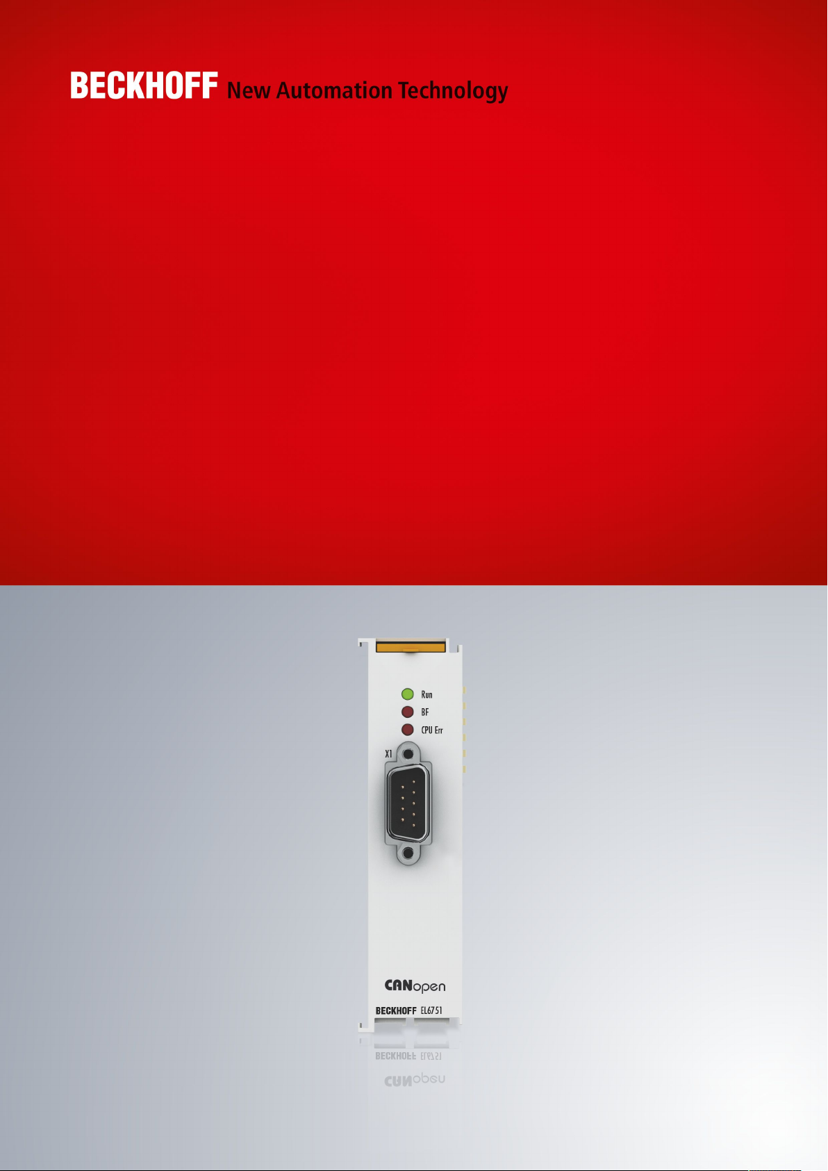
From 2014/01 the revision is shown on the outside of the IP20 terminals, see Fig. “EL5021 EL terminal,
standard IP20 IO device with batch number and revision ID (since 2014/01)”.
• The type, version and revision are read as decimal numbers, even if they are technically saved in
hexadecimal.
Identification number
Beckhoff EtherCAT devices from the different lines have different kinds of identification numbers:
Production lot/batch number/serial number/date code/D number
The serial number for Beckhoff IO devices is usually the 8-digit number printed on the device or on a sticker.
The serial number indicates the configuration in delivery state and therefore refers to a whole production
batch, without distinguishing the individual modules of a batch.
Structure of the serial number: KKYYFFHH
KK - week of production (CW, calendar week)
YY - year of production
FF - firmware version
HH - hardware version
EL67518 Version: 3.7
Page 9
Foreword
Example with
Ser. no.: 12063A02: 12 - production week 12 06 - production year 2006 3A - firmware version 3A 02 hardware version 02
Exceptions can occur in the IP67 area, where the following syntax can be used (see respective device
documentation):
Syntax: D ww yy x y z u
D - prefix designation
ww - calendar week
yy - year
x - firmware version of the bus PCB
y - hardware version of the bus PCB
z - firmware version of the I/O PCB
u - hardware version of the I/O PCB
Example: D.22081501 calendar week 22 of the year 2008 firmware version of bus PCB: 1 hardware version
of bus PCB: 5 firmware version of I/O PCB: 0 (no firmware necessary for this PCB) hardware version of I/O
PCB: 1
Unique serial number/ID, ID number
In addition, in some series each individual module has its own unique serial number.
See also the further documentation in the area
• IP67: EtherCAT Box
• Safety: TwinSafe
• Terminals with factory calibration certificate and other measuring terminals
Examples of markings
Fig.1: EL5021 EL terminal, standard IP20 IO device with serial/ batch number and revision ID (since
2014/01)
EL6751 9Version: 3.7
Page 10
Foreword
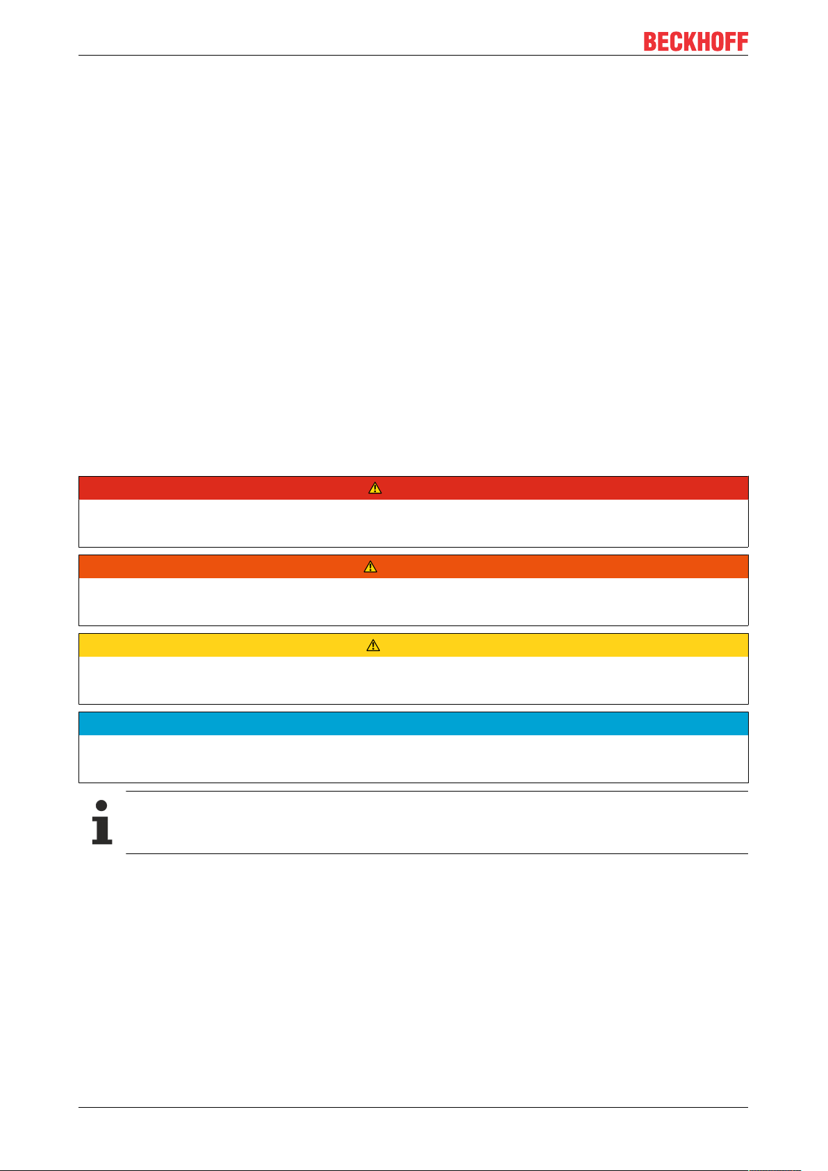
Fig.2: EK1100 EtherCAT coupler, standard IP20 IO device with serial/ batch number
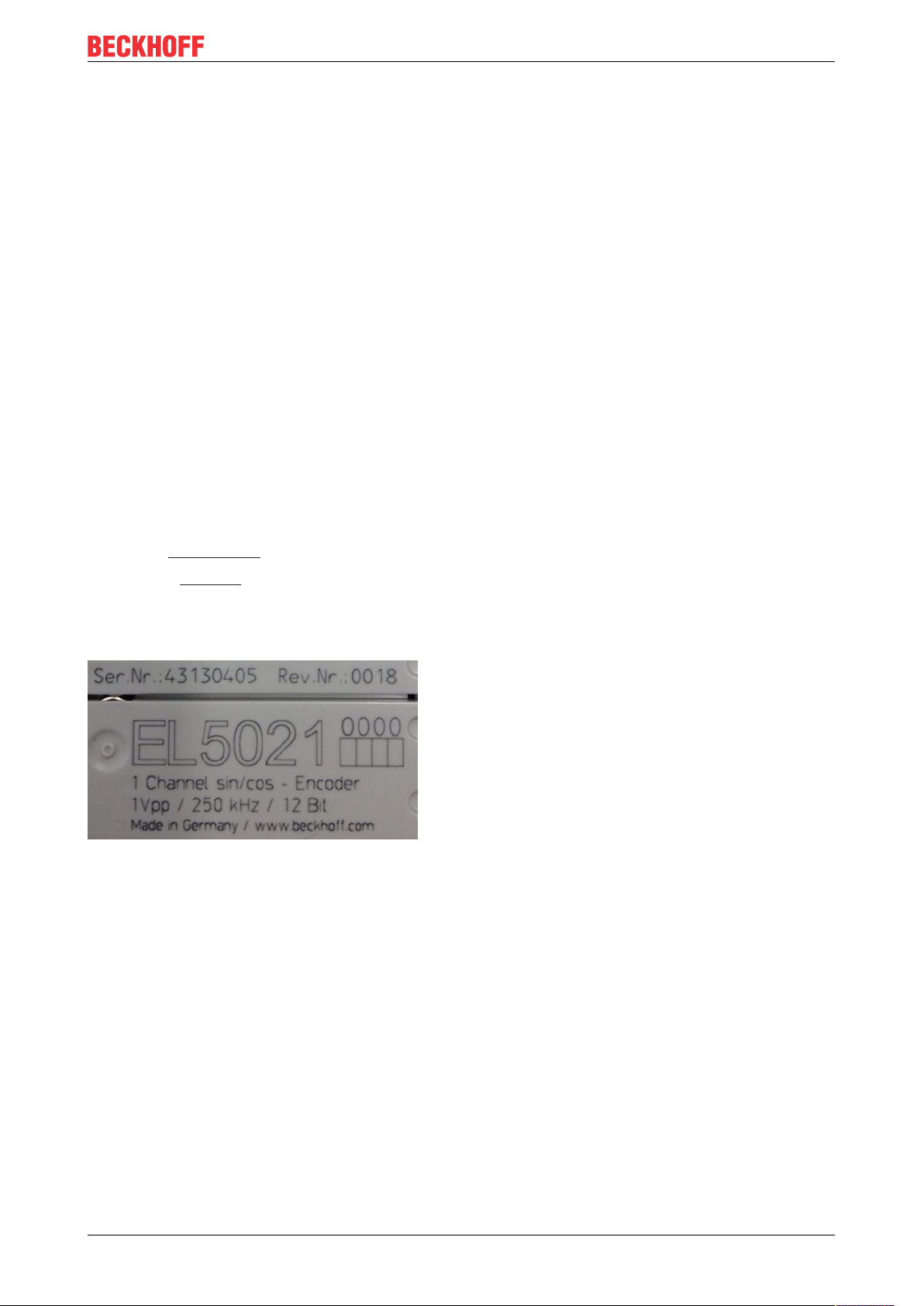
Fig.3: CU2016 switch with serial/ batch number
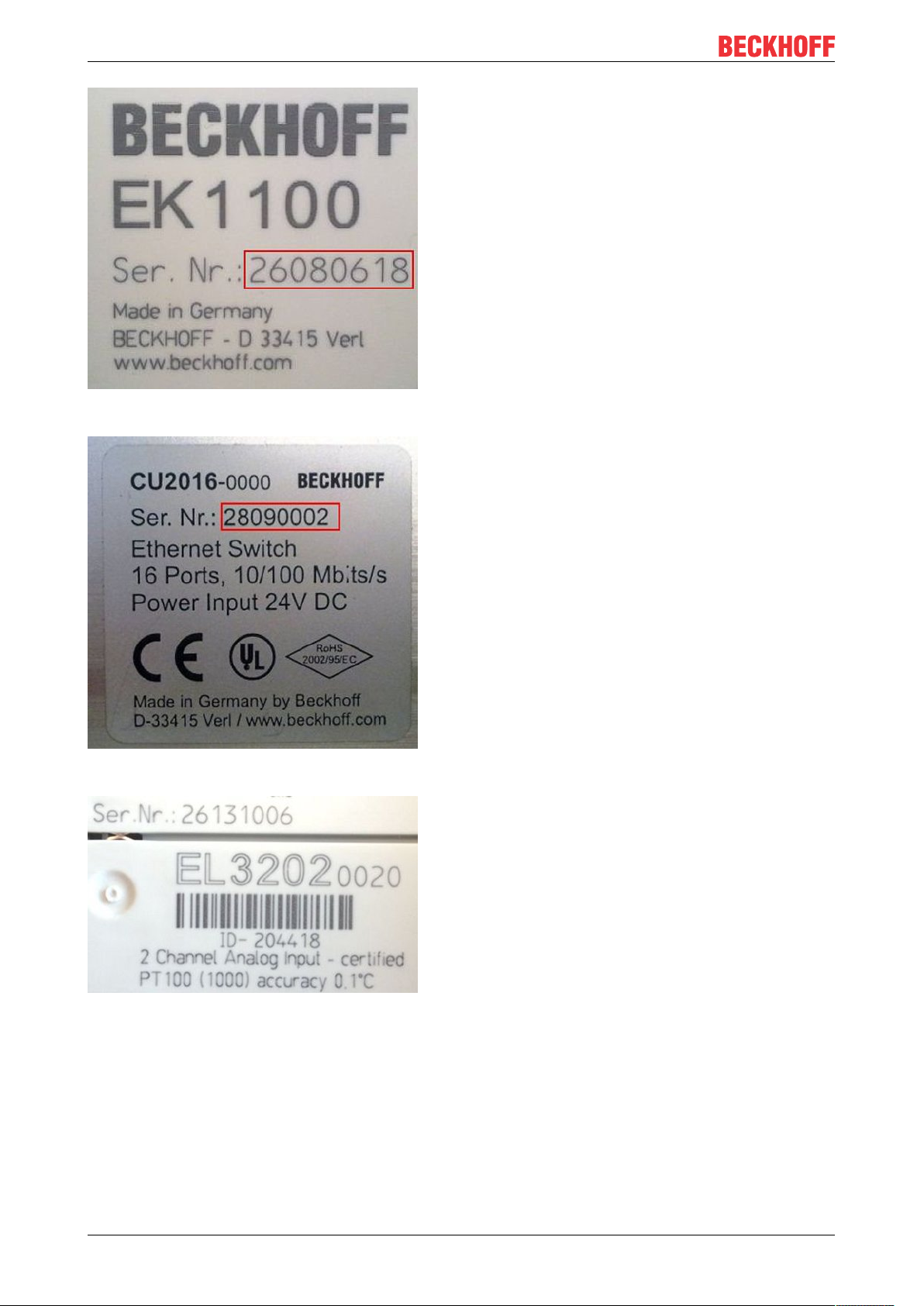
Fig.4: EL3202-0020 with serial/ batch number 26131006 and unique ID-number 204418
EL675110 Version: 3.7
Page 11
Foreword
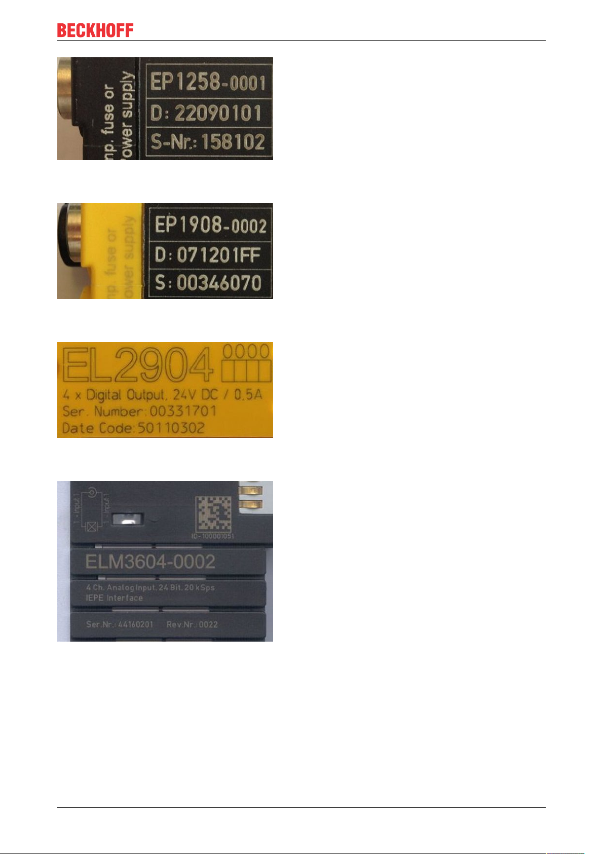
Fig.5: EP1258-00001 IP67 EtherCAT Box with batch number/ date code 22090101 and unique serial
number 158102
Fig.6: EP1908-0002 IP67 EtherCAT Safety Box with batch number/ date code 071201FF and unique serial
number 00346070
Fig.7: EL2904 IP20 safety terminal with batch number/ date code 50110302 and unique serial number
00331701
Fig.8: ELM3604-0002 terminal with unique ID number (QR code) 100001051 and serial/ batch number
44160201
EL6751 11Version: 3.7
Page 12
Foreword
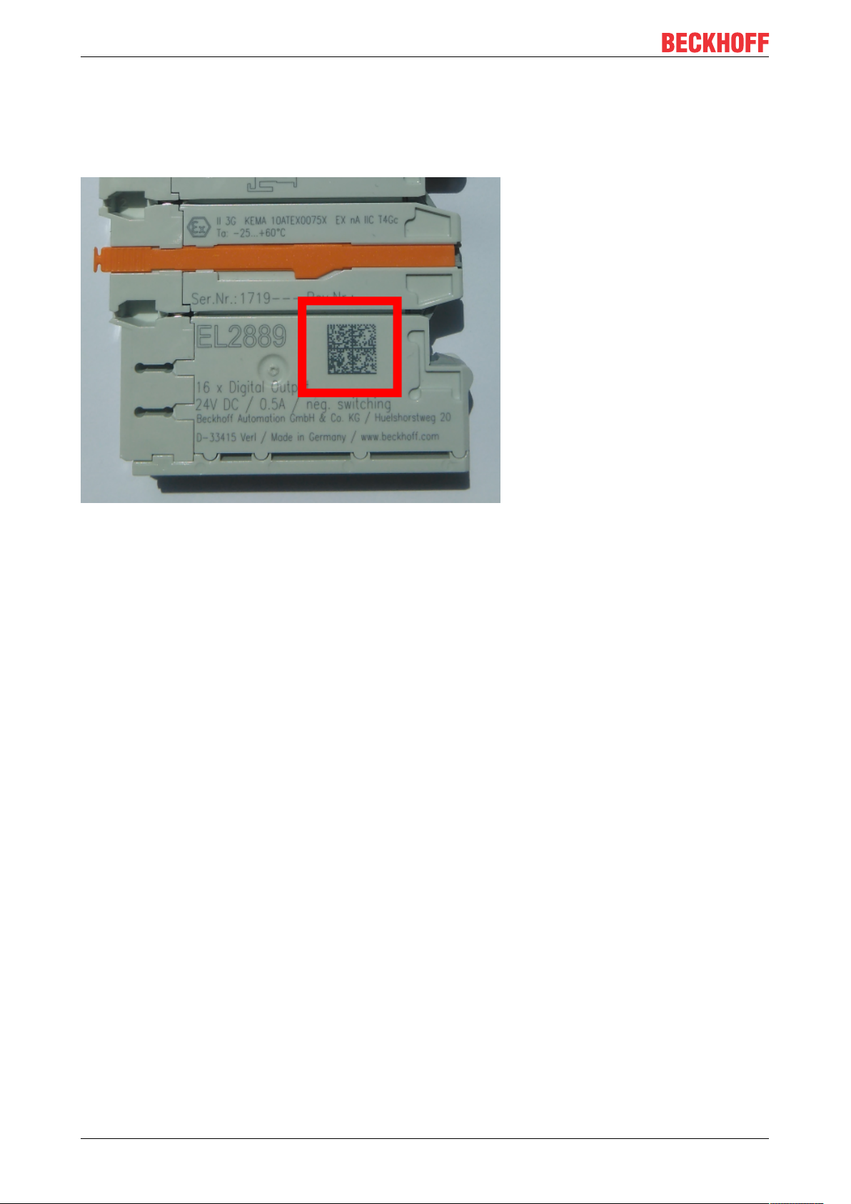
1.4.1 Beckhoff Identification Code (BIC)
The Beckhoff Identification Code (BIC) is increasingly being applied to Beckhoff products to uniquely identify
the product. The BIC is represented as a Data Matrix Code (DMC, code scheme ECC200), the content is
based on the ANSI standard MH10.8.2-2016.
Fig.9: BIC as data matrix code (DMC, code scheme ECC200)
The BIC will be introduced step by step across all product groups.
Depending on the product, it can be found in the following places:
• on the packaging unit
• directly on the product (if space suffices)
• on the packaging unit and the product
The BIC is machine-readable and contains information that can also be used by the customer for handling
and product management.
Each piece of information can be uniquely identified using the so-called data identifier
(ANSIMH10.8.2-2016). The data identifier is followed by a character string. Both together have a maximum
length according to the table below. If the information is shorter, spaces are added to it. The data under
positions 1 to 4 are always available.
The following information is contained:
EL675112 Version: 3.7
Page 13

Item
Type of
no.
information
1 Beckhoff order
number
2 Beckhoff Traceability
Number (BTN)
3 Article description Beckhoff article
4 Quantity Quantity in packaging
5 Batch number Optional: Year and week
6 ID/serial number Optional: Present-day
7 Variant number Optional: Product variant
...
Explanation Data
Beckhoff order number 1P 8 1P072222
Unique serial number,
see note below
description, e.g.
EL1008
unit, e.g. 1, 10, etc.
of production
serial number system,
e.g. with safety products
or calibrated terminals
number on the basis of
standard products
Foreword
Number of digits
identifier
S 12 SBTNk4p562d7
1K 32 1KEL1809
Q 6 Q1
2P 14 2P401503180016
51S 12 51S678294104
30P 32 30PF971, 2*K183
incl. data identifier
Example
Further types of information and data identifiers are used by Beckhoff and serve internal processes.
Structure of the BIC
Example of composite information from item 1 to 4 and 6. The data identifiers are marked in red for better
display:
BTN
An important component of the BIC is the Beckhoff Traceability Number (BTN, item no.2). The BTN is a
unique serial number consisting of eight characters that will replace all other serial number systems at
Beckhoff in the long term (e.g. batch designations on IO components, previous serial number range for
safety products, etc.). The BTN will also be introduced step by step, so it may happen that the BTN is not yet
coded in the BIC.
NOTE
This information has been carefully prepared. However, the procedure described is constantly being further
developed. We reserve the right to revise and change procedures and documentation at any time and without prior notice. No claims for changes can be made from the information, illustrations and descriptions in
this information.
EL6751 13Version: 3.7
Page 14
Product overview
2 Product overview
2.1 Introduction
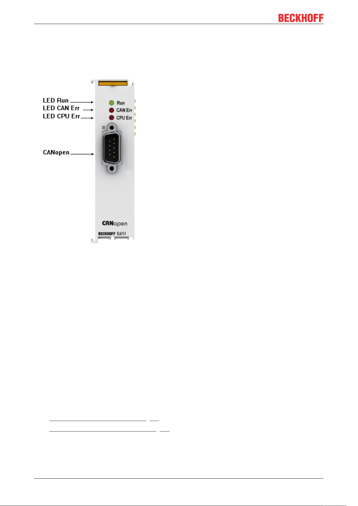
Fig.10: EL6751
Master and slave terminals for CANopen
The master and slave terminals for CANopen correspond to the FC5101 PCI card from Beckhoff. Thanks to
the connection via Ethernet, no PCI slots are required in the PC. Within an EtherCAT terminal network, it
enables the integration of any CANopen devices. In addition, general CAN messages can be sent or
received – without having to bother with CAN frames in the applications program. The EL6751 is
alternatively available in a master or slave version and has a powerful protocol implementation with many
features:
• All CANopen PDO communication types are supported: event-controlled, time-controlled (event timer),
synchronous.
• Synchronization with the PC controller's task cycle.
• SYNC cycle with quartz precision for drive synchronization, zero cumulative jitter.
• Parameter communication (SDO) at start-up and at runtime.
• Emergency message handling, guarding and heartbeat.
• Powerful parameter and diagnostics interfaces.
• Online bus load display
Quick links
• EL6751 - CANopen master terminal [}76]
• EL6751-0010 - CANopen slave terminal [}82]
EL675114 Version: 3.7
Page 15

Product overview
2.2 Technical data
Technical data EL6751-0000 EL6751-0010
Bus system CANopen
Version Master Slave
Number of fieldbus channels 1
Data transfer rate 10, 20, 50, 100, 125, 250, 500, 800 or 1000kbit/s
Bus interface D-Sub 9-pole connector according to CANopen specification,
galvanically uncoupled
Bus devices maximum 127 slaves
Communication CANopen network master and
CANopen manager
Diagnostics Status LEDs
Power supply via the E-bus
Current consumption via E-bus typ. 230 mA
Electrical isolation 500 V (E-bus/CANopen)
Configuration with TwinCAT System Manager
Weight approx. 70 g
Permissible ambient temperature range
during operation
Permissible ambient temperature range
during storage
Permissible relative humidity 95%, no condensation
Dimensions (W x H x D) approx. 26 mm x 100 mm x 52 mm (width aligned: 23mm)
Mounting [}18]
Vibration/shock resistance conforms to EN 60068-2-6 / EN 60068-2-27
EMC immunity/emission conforms to EN 61000-6-2 / EN 61000-6-4
Protection class IP20
Installation position variable
Approval CE, EAC
-25°C ... +60°C (extended temperature range)
-40°C ... +85°C
on 35 mm mounting rail conforms to EN 60715
ATEX [}25]
UL [}26]
CANopen slave
EL6751 15Version: 3.7
Page 16
Product overview
2.3 CANopen Introduction
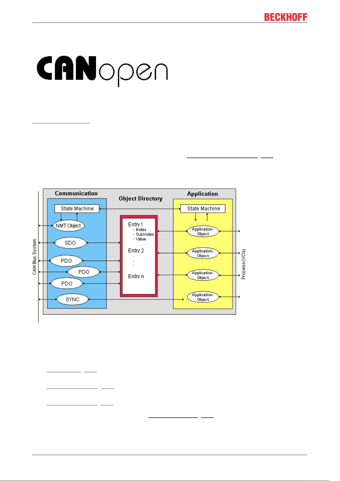
Fig.11: CANopenLogo
CANopen is a widely used CAN application layer, developed by the CAN-in-Automation association (CiA,
http://www.can-cia.org), and which has meanwhile been adopted for international standardization.
Device Model
CANopen consists of the protocol definitions (communication profile) and of the device profiles that
standardize the data contents for the various device classes. Process data objects (PDO) [}102] are used for
fast communication of input and output data. The CANopen device parameters and process data are stored
in a structured object directory. Any data in this object directory is accessed via service data objects (SDO).
There are, additionally, a few special objects (such as telegram types) for network management (NMT),
synchronization, error messages and so on.
Fig.12: CANopen Device Model
Communication Types
CANopen defines a number of communication classes for the input and output data (process data objects):
• Event driven [}105]: Telegrams are sent as soon as their contents have changed. This means that the
process image as a whole is not continuously transmitted, only its changes.
• Cyclic synchronous [}105]: A SYNC telegram causes the modules to accept the output data that was
previously received, and to send new input data.
• Requested (polled) [}102]: A CAN data request telegram causes the modules to send their input data.
The desired communication type is set by the Transmission Type [}102] parameter.
EL675116 Version: 3.7
Page 17

Product overview
Device Profile
The BECKHOFF CANopen devices support all types of I/O communication, and correspond to the device
profile for digital and analog input/output modules (DS401 Version 1). For reasons of backwards
compatibility, the default mapping was not adapted to the DS401 V2 profile version.
Data transfer rates
Nine transmission rates [}120] from 10 kbit/s up to 1 Mbit/s are available for different bus lengths. The
effective utilization of the bus bandwidth allows CANopen to achieve short system reaction times at relatively
low data rates.
Topology
CAN is based on a linear topology [}27]. The number of devices participating in each network is logically
limited by CANopen to 128, but physically the present generation of drivers allows up to 64 nodes in one
network segment. The maximum possible size of the network for any particular data rate is limited by the
signal propagation delay required on the bus medium. For 1Mbit/s, for instance, the network may extend
25m, whereas at 50kbit/s the network may reach up to 1000m. At low data rates the size of the network
can be increased by repeaters, which also allow the construction of tree structures.
Bus access procedures
CAN utilizes the Carrier Sense Multiple Access (CSMA) procedure, i.e. all participating devices have the
same right of access to the bus and may access it as soon as it is free (multi-master bus access). The
exchange of messages is thus not device-oriented but message-oriented. This means that every message is
unambiguously marked with a prioritized identifier. In order to avoid collisions on the bus when messages
are sent by different devices, a bit-wise bus arbitration is carried out at the start of the data transmission. The
bus arbitration assigns bus bandwidth to the messages in the sequence of their priority. At the end of the
arbitration phase only one bus device occupies the bus, collisions are avoided and the bandwidth is optimally
exploited.
Configuration and parameterization
The TwinCAT System Manager allows all the CANopen parameters to be set conveniently. An "eds" file (an
electronic data sheet) is available on the Beckhoff website (http://www.beckhoff.de) for the parameterization
of Beckhoff CANopen devices using configuration tools from other manufacturers.
Certification
The Beckhoff CANopen devices have a powerful implementation of the protocol, and are certified by the
CAN in Automation Association (http://www.can-cia.org).
EL6751 17Version: 3.7
Page 18

Mounting and wiring
3 Mounting and wiring
3.1 Recommended mounting rails
Terminal Modules und EtherCAT Modules of KMxxxx and EMxxxx series, same as the terminals of the
EL66xx and EL67xx series can be snapped onto the following recommended mounting rails:
DIN Rail TH 35-7.5 with 1 mm material thickness (according to EN 60715)
DIN Rail TH 35-15 with 1,5 mm material thickness
Pay attention to the material thickness of the DIN Rail
Terminal Modules und EtherCAT Modules of KMxxxx and EMxxxx series, same as the terminals of
the EL66xx and EL67xx series does not fit to the DIN Rail TH 35-15 with 2,2 to 2,5 mm material
thickness (according to EN 60715)!
3.2 Mounting and demounting - terminals with traction lever unlocking
The terminal modules are fastened to the assembly surface with the aid of a 35 mm mounting rail (e.g.
mounting rail TH 35-15).
Fixing of mounting rails
The locking mechanism of the terminals and couplers extends to the profile of the mounting rail. At
the installation, the locking mechanism of the components must not come into conflict with the fixing
bolts of the mounting rail. To mount the recommended mounting rails under the terminals and couplers, you should use flat mounting connections (e.g. countersunk screws or blind rivets).
WARNING
Risk of electric shock and damage of device!
Bring the bus terminal system into a safe, powered down state before starting installation, disassembly or
wiring of the Bus Terminals!
Mounting
• Fit the mounting rail to the planned assembly location.
EL675118 Version: 3.7
Page 19
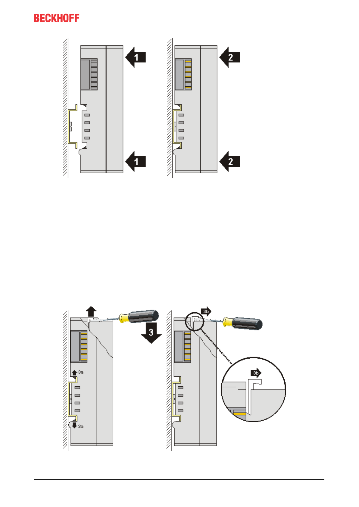
and press (1) the terminal module against the mounting rail until it latches in place on the mounting
rail (2).
• Attach the cables.
Mounting and wiring
Demounting
• Remove all the cables. Thanks to the KM/EM connector, it is not necessary to remove all the cables
separately for this, but for each KM/EM connector simply undo 2 screws so that you can pull them off
(fixed wiring)!
• Lever the unlatching hook on the left-hand side of the terminal module upwards with a screwdriver (3).
As you do this
◦ an internal mechanism pulls the two latching lugs (3a) from the top hat rail back into the terminal
module,
◦ the unlatching hook moves forwards (3b) and engages
EL6751 19Version: 3.7
Page 20
Mounting and wiring
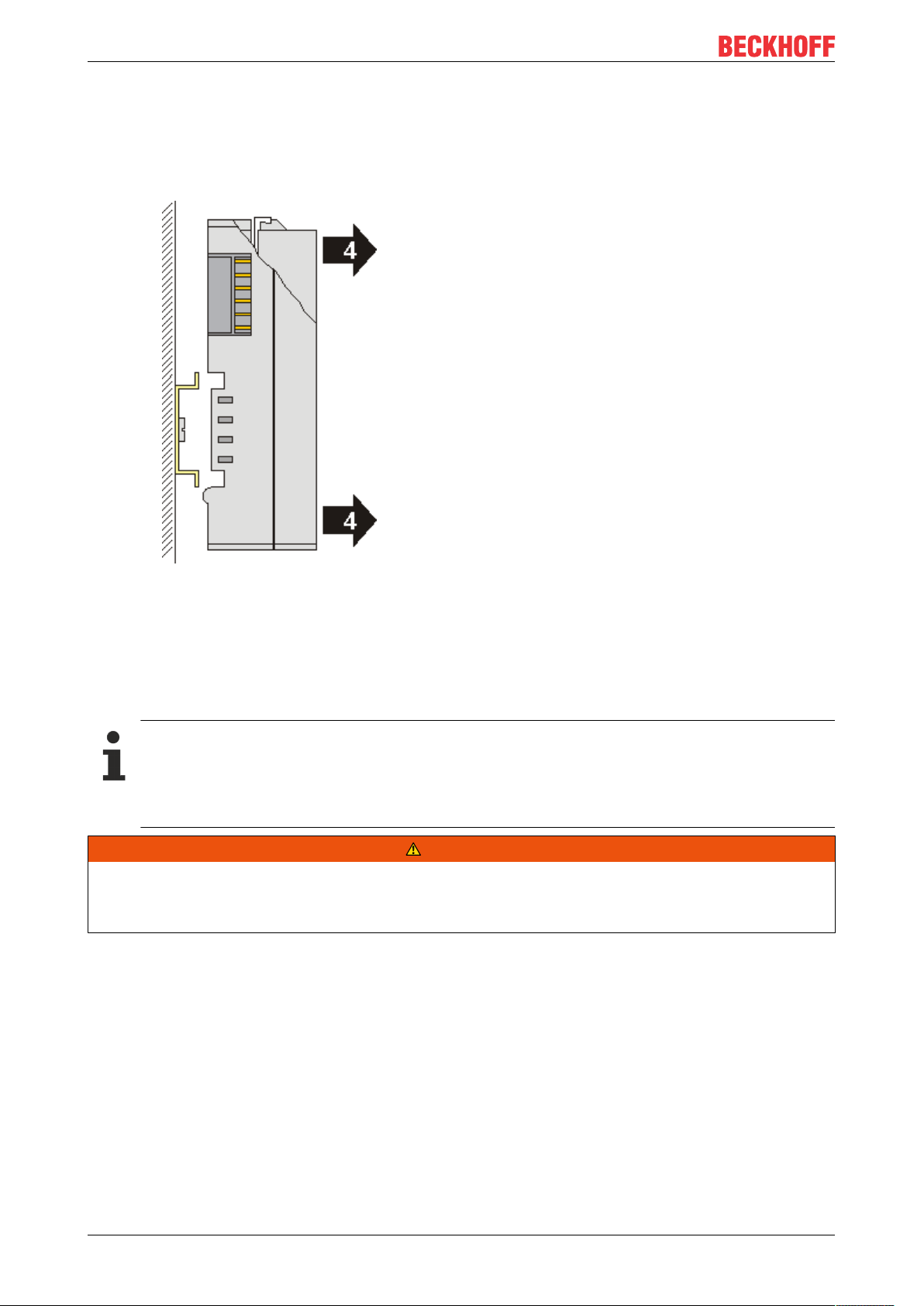
• In the case 32 and 64 channel terminal modules (KMxxx4 and KMxxx8 or EMxxx4 and EMxxx8) you
now lever the second unlatching hook on the right-hand side of the terminal module upwards in the
same way.
• Pull (4) the terminal module away from the mounting surface.
3.3 Mounting and demounting - terminals with front unlocking
The terminal modules are fastened to the assembly surface with the aid of a 35 mm mounting rail (e.g.
mounting rail TH 35-15).
Fixing of mounting rails
The locking mechanism of the terminals and couplers extends to the profile of the mounting rail. At
the installation, the locking mechanism of the components must not come into conflict with the fixing
bolts of the mounting rail. To mount the recommended mounting rails under the terminals and couplers, you should use flat mounting connections (e.g. countersunk screws or blind rivets).
WARNING
Risk of electric shock and damage of device!
Bring the bus terminal system into a safe, powered down state before starting installation, disassembly or
wiring of the Bus Terminals!
Mounting
• Fit the mounting rail to the planned assembly location.
EL675120 Version: 3.7
Page 21
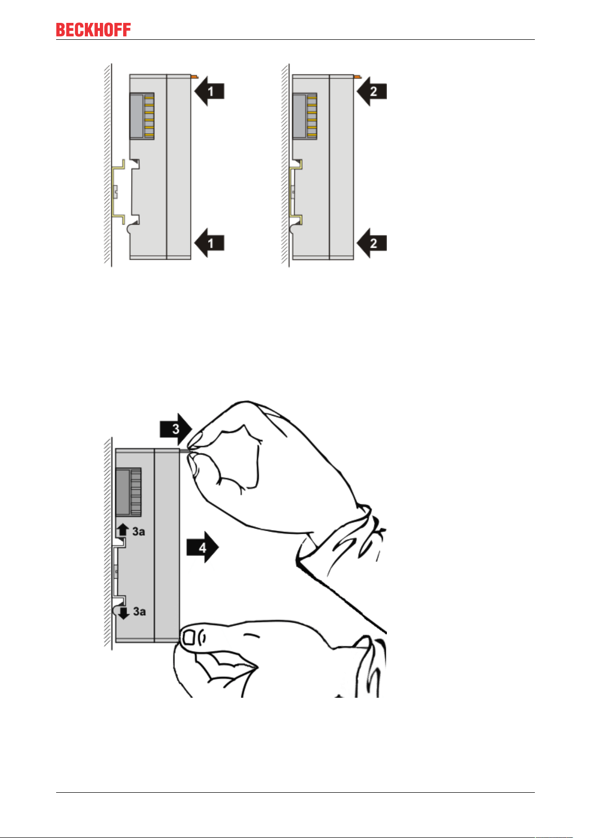
and press (1) the terminal module against the mounting rail until it latches in place on the mounting
rail (2).
• Attach the cables.
Mounting and wiring
Demounting
• Remove all the cables.
• Lever the unlatching hook back with thumb and forefinger (3). An internal mechanism pulls the two
latching lugs (3a) from the top hat rail back into the terminal module.
• Pull (4) the terminal module away from the mounting surface.
Avoid canting of the module; you should stabilize the module with the other hand, if required.
EL6751 21Version: 3.7
Page 22
Mounting and wiring
3.4 Installation positions
NOTE
Constraints regarding installation position and operating temperature range
Please refer to the technical data for a terminal to ascertain whether any restrictions regarding the installation position and/or the operating temperature range have been specified. When installing high power dissipation terminals ensure that an adequate spacing is maintained between other components above and below the terminal in order to guarantee adequate ventilation!
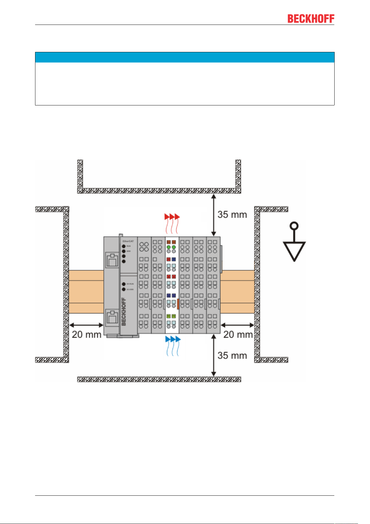
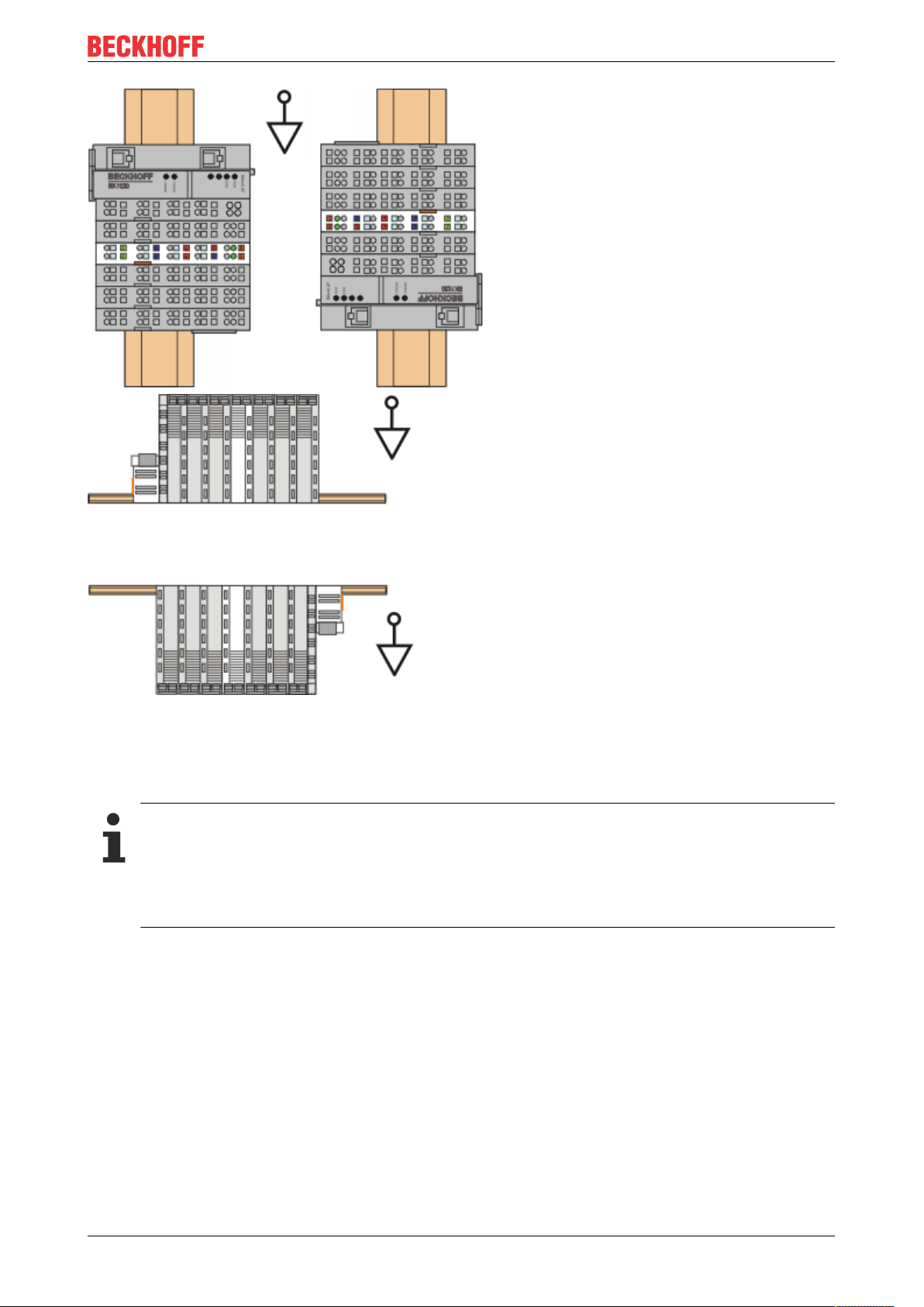
Optimum installation position (standard)
The optimum installation position requires the mounting rail to be installed horizontally and the connection
surfaces of the EL/KL terminals to face forward (see Fig. Recommended distances for standard installation
position). The terminals are ventilated from below, which enables optimum cooling of the electronics through
convection. “From below” is relative to the acceleration of gravity.
Fig.13: Recommended distances for standard installation position
Compliance with the distances shown in Fig. Recommended distances for standard installation position is
recommended.
Other installation positions
All other installation positions are characterized by different spatial arrangement of the mounting rail - see
Fig Other installation positions.
The minimum distances to ambient specified above also apply to these installation positions.
EL675122 Version: 3.7
Page 23
Mounting and wiring
Fig.14: Other installation positions
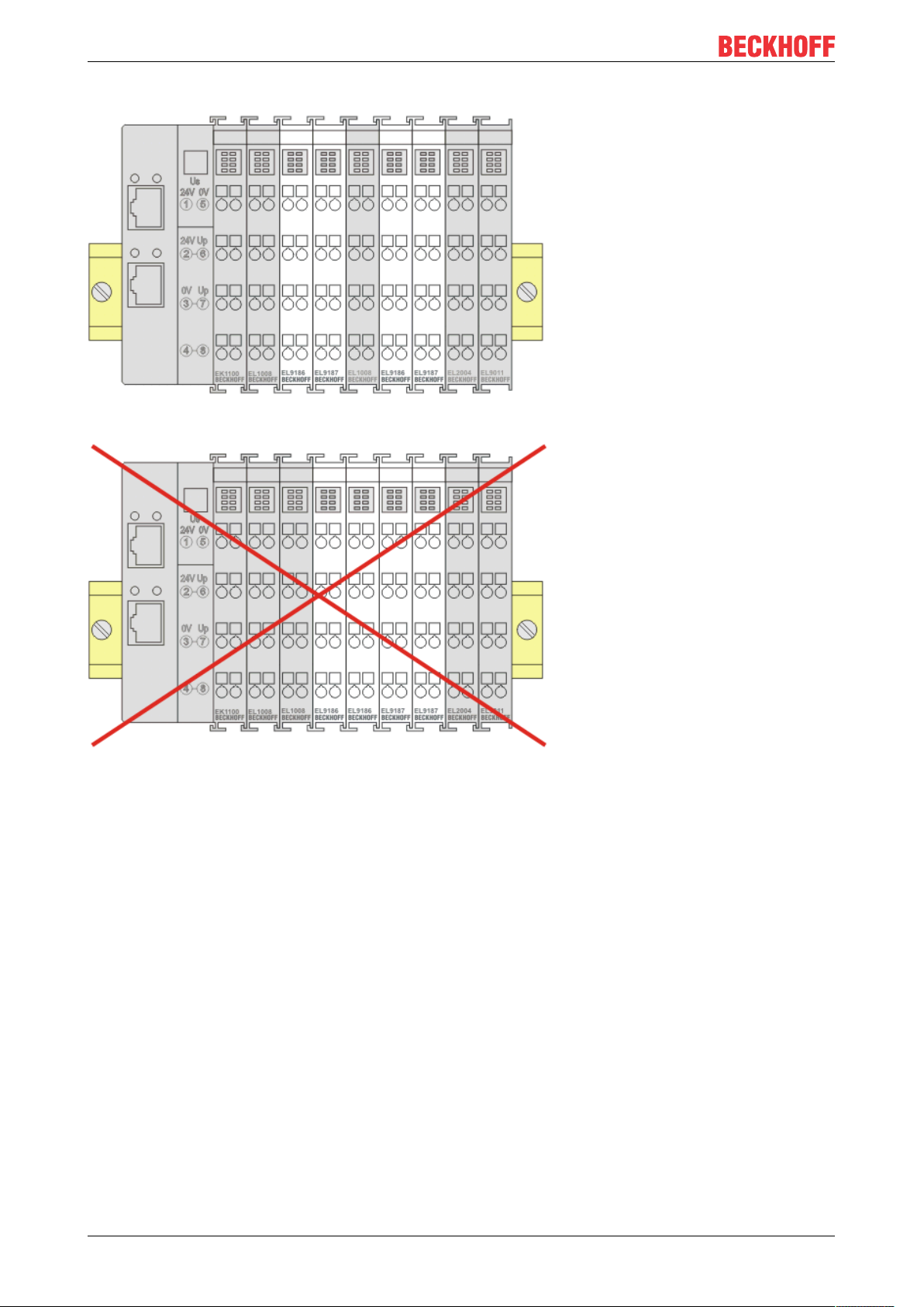
3.5 Positioning of passive Terminals
Hint for positioning of passive terminals in the bus terminal block
EtherCAT Terminals (ELxxxx / ESxxxx), which do not take an active part in data transfer within the
bus terminal block are so called passive terminals. The passive terminals have no current consumption out of the E-Bus.
To ensure an optimal data transfer, you must not directly string together more than two passive terminals!
EL6751 23Version: 3.7
Page 24
Mounting and wiring
Examples for positioning of passive terminals (highlighted)
Fig.15: Correct positioning
Fig.16: Incorrect positioning
EL675124 Version: 3.7
Page 25

Mounting and wiring
3.6 ATEX - Special conditions (extended temperature range)
WARNING
Observe the special conditions for the intended use of Beckhoff fieldbus components with
extended temperature range (ET) in potentially explosive areas (directive 2014/34/EU)!
• The certified components are to be installed in a suitable housing that guarantees a protection class of at
least IP54 in accordance with EN60079-15! The environmental conditions during use are thereby to be
taken into account!
• For dust (only the fieldbus components of certificate no. KEMA 10ATEX0075 X Issue 9): The equipment
shall be installed in a suitable enclosure providing a degree of protection of IP54 according to EN
60079-0 for group IIIA or IIIB and IP6X for group IIIC, taking into account the environmental conditions
under which the equipment is used.
• If the temperatures during rated operation are higher than 70°C at the feed-in points of cables, lines or
pipes, or higher than 80°C at the wire branching points, then cables must be selected whose temperature data correspond to the actual measured temperature values!
• Observe the permissible ambient temperature range of -25 to 60°C for the use of Beckhoff fieldbus components with extended temperature range (ET) in potentially explosive areas!
• Measures must be taken to protect against the rated operating voltage being exceeded by more than
40% due to short-term interference voltages!
• The individual terminals may only be unplugged or removed from the Bus Terminal system if the supply
voltage has been switched off or if a non-explosive atmosphere is ensured!
• The connections of the certified components may only be connected or disconnected if the supply voltage has been switched off or if a non-explosive atmosphere is ensured!
• The fuses of the KL92xx/EL92xx power feed terminals may only be exchanged if the supply voltage has
been switched off or if a non-explosive atmosphere is ensured!
• Address selectors and ID switches may only be adjusted if the supply voltage has been switched off or if
a non-explosive atmosphere is ensured!
Standards
The fundamental health and safety requirements are fulfilled by compliance with the following standards:
• EN 60079-0:2012+A11:2013
• EN 60079-15:2010
• EN 60079-31:2013 (only for certificate no. KEMA 10ATEX0075 X Issue 9)
EL6751 25Version: 3.7
Page 26

Mounting and wiring
Marking
The Beckhoff fieldbus components with extended temperature range (ET) certified according to the ATEX
directive for potentially explosive areas bear the following marking:
II 3G KEMA 10ATEX0075 X Ex nA IIC T4 Gc Ta: -25 … +60°C
II 3D KEMA 10ATEX0075 X Ex tc IIC T135°C Dc Ta: -25 ... +60°C
(only for fieldbus components of certificate no. KEMA 10ATEX0075 X Issue 9)
or
II 3G KEMA 10ATEX0075 X Ex nC IIC T4 Gc Ta: -25 … +60°C
II 3D KEMA 10ATEX0075 X Ex tc IIC T135°C Dc Ta: -25 ... +60°C
(only for fieldbus components of certificate no. KEMA 10ATEX0075 X Issue 9)
3.7 Continuative documentation about explosion protection
Explosion protection for terminal systems
Pay also attention to the continuative documentation
Notes on the use of the Beckhoff terminal systems in hazardous areas according to ATEX and
IECEx
that is available for download on the Beckhoff homepage https:\\www.beckhoff.com!
3.8 UL notice
Application
Beckhoff EtherCAT modules are intended for use with Beckhoff’s UL Listed EtherCAT System only.
Examination
For cULus examination, the Beckhoff I/O System has only been investigated for risk of fire
and electrical shock (in accordance with UL508 and CSAC22.2 No.142).
For devices with Ethernet connectors
Not for connection to telecommunication circuits.
Basic principles
UL certification according to UL508. Devices with this kind of certification are marked by this sign:
EL675126 Version: 3.7
Page 27
Mounting and wiring
3.9 CANopen cabling
Notes related to checking the CAN wiring can be found in the Trouble Shooting [}180] section.
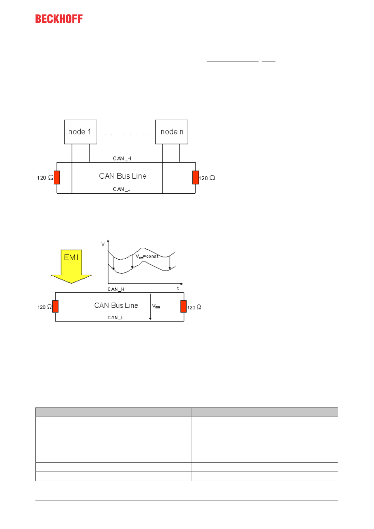
3.9.1 CAN topology
CAN is a 2-wire bus system, to which all participating devices are connected in parallel (i.e. using short drop
lines). The bus must be terminated at each end with a 120 (or 121) Ohm terminating resistor to prevent
reflections. This is also necessary even if the cable lengths are very short!
Fig.17: Termination of the bus with a 120 Ohm termination resistor
Since the CAN signals are represented on the bus as the difference between the two levels, the CAN leads
are not very sensitive to incoming interference (EMI): Both leads are affected, so the interference has very
little effect on the difference.
Fig.18: Insensitivity to incoming interference
3.9.2 Bus length
The maximum length of a CAN bus is primarily limited by the signal propagation delay. The multi-master bus
access procedure (arbitration) requires signals to reach all the nodes at effectively the same time (before the
sampling within a bit period). Since the signal propagation delays in the CAN connecting equipment
(transceivers, opto-couplers, CAN controllers) are almost constant, the line length must be chosen in
accordance with the baud rate:
Baud rate Bus length
1 Mbit/s < 20 m*
500 kbit/s < 100 m
250 kbit/s < 250 m
125 kbit/s < 500 m
50 kbit/s < 1000 m
20 kbit/s < 2500 m
10 kbit/s < 5000 m
EL6751 27Version: 3.7
Page 28
Mounting and wiring
*) A figure of 40 m at 1 Mbit/s is often found in the CAN literature. This does not, however, apply to networks
with optically isolated CAN controllers. The worst case calculation for opto-couplers yields a figure 5 m at 1
Mbit/s - in practice, however, 20 m can be reached without difficulty.
It may be necessary to use repeaters for bus lengths greater than 1000 m.
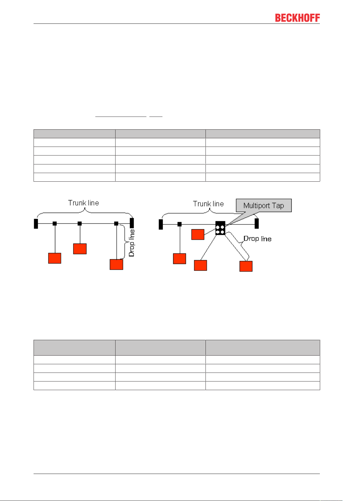
3.9.3 Drop lines
Drop lines must always be avoided as far as possible, since they inevitably cause reflections. The reflections
caused by drop lines are not however usually critical, provided they have decayed fully before the sampling
time. In the case of the bit timing settings [}120] selected in the Bus Couplers it can be assumed that this is
the case, provided the following drop line lengths are not exceeded:
Baud rate Drop line length Total length of all drop lines
1 Mbit/s < 1 m < 5 m
500 kbit/s <5m <25m
250 kbit/s <10m <50m
125 kbit/s <20m <100m
50 kbit/s <50m <250m
Drop lines must not have terminating resistors.
Fig.19: Sample topology of drop lines
3.9.4 Star Hub (Multiport Tap)
Shorter drop line lengths must be maintained when passive distributors ("multiport taps"), such as the
Beckhoff ZS5052-4500 Distributor Box. The following table indicates the maximum drop line lengths and the
maximum length of the trunk line (without the drop lines):
Baud rate Drop line length with multiport
topology
1 Mbit/s < 0,3 m < 25 m
500 kbit/s < 1,2 m < 66 m
250 kbit/s <2,4m <120m
125 kbit/s <4,8m <310m
Trunk line length (without drop lines)
3.9.5 CAN cable
Screened twisted-pair cables (2x2) with a characteristic impedance of between 108 and 132 Ohm is
recommended for the CAN wiring. If the CAN transceiver’s reference potential (CAN ground) is not to be
connected, the second pair of conductors can be omitted. (This is only recommended for networks of small
physical size with a common power supply for all the participating devices).
EL675128 Version: 3.7
Page 29
Mounting and wiring
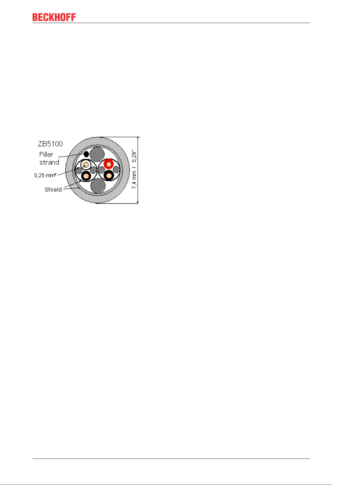
ZB5100 CAN Cable
A high quality CAN cable with the following properties is included in Beckhoff's range:
• 2 x 2 x 0.25 mm² (AWG 24) twisted pairs, cable colors: red/black + white/black
• double screened
• braided screen with filler strand (can be attached directly to pin 3 of the 5-pin connection terminal)
• flexible (minimum bending radius 35 mm when bent once, 70 mm for repeated bending)
• characteristic impedance (60 kHz): 120 ohm
• conductor resistance < 80 Ohm/km
• sheath: grey PVC, outside diameter 7.3 +/- 0.4 mm
• Weight: 64 kg/km.
• printed with "Beckhoff ZB5100 CAN-BUS 2x2x0.25" and meter marking (length data every 20cm)
Fig.20: Structure of CAN cable ZB5100
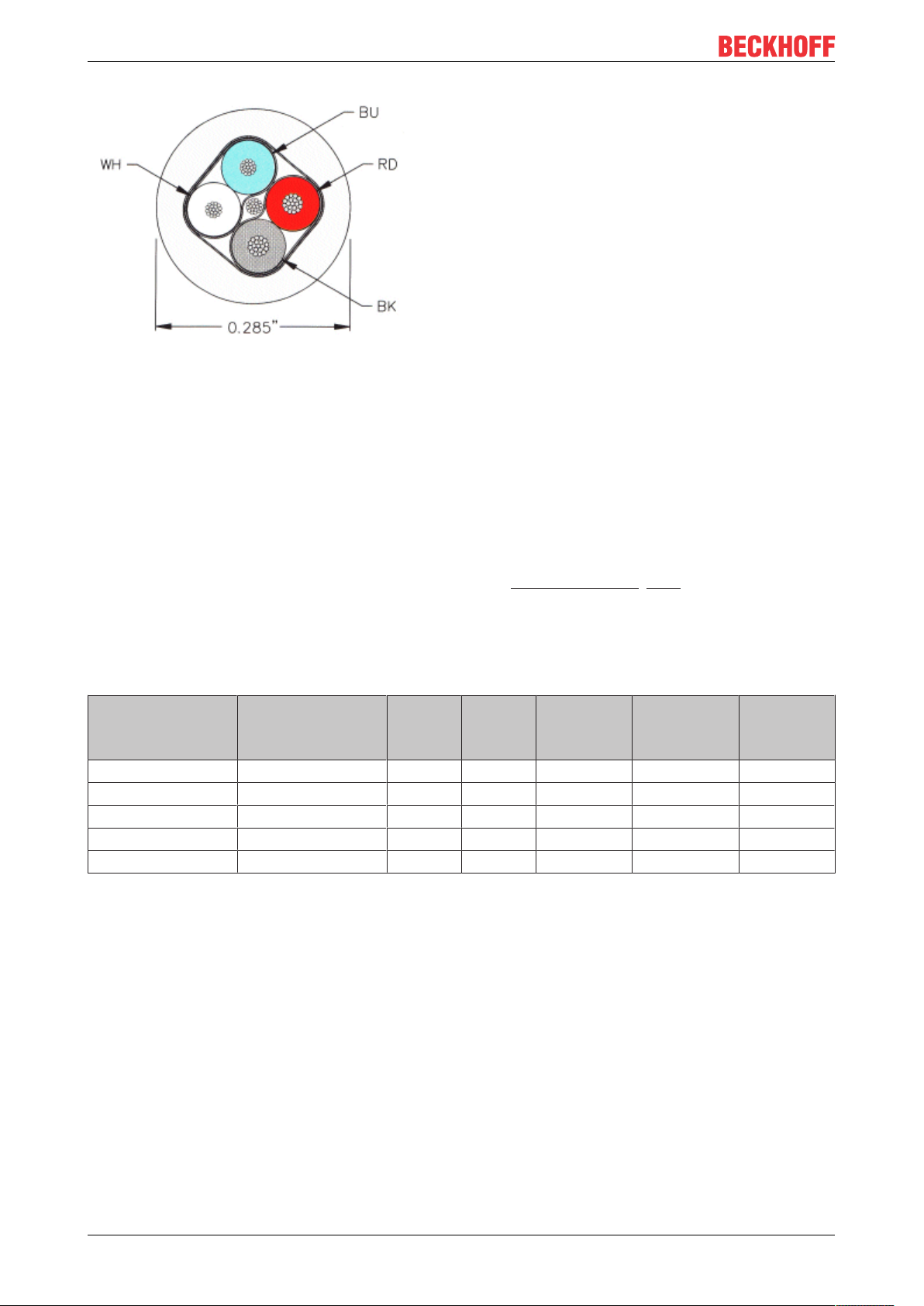
ZB5200 CAN/DeviceNet Cable
The ZB5200 cable material corresponds to the DeviceNet specification, and is also suitable for CANopen
systems. The ready-made ZK1052-xxxx-xxxx bus cables for the Fieldbus Box modules are made from this
cable material. It has the following specification:
• 2 x 2 x 0.34 mm² (AWG 22) twisted pairs
• double screened, braided screen with filler strand
• characteristic impedance (1 MHz): 126 ohm
• Conductor resistance 54 Ohm/km
• sheath: grey PVC, outside diameter 7.3 mm
• printed with "InterlinkBT DeviceNet Type 572" as well as UL and CSA ratings
• stranded wire colors correspond to the DeviceNet specification
• UL recognized AWM Type 2476 rating
• CSA AWM I/II A/B 80°C 300V FT1
• corresponds to the DeviceNet "Thin Cable" specification
EL6751 29Version: 3.7
Page 30
Mounting and wiring
Fig.21: Structure of CAN/DeviceNet cable ZB5200
3.9.6 Shielding
The screen is to be connected over the entire length of the bus cable, and only galvanically grounded at one
point, in order to avoid ground loops.
The design of the screening, in which HF interference is diverted through R/C elements to the mounting rail
assumes that the rail is appropriately earthed and free from interference. If this is not the case, it is possible
that HF interference will be transmitted from the mounting rail to the screen of the bus cable. In that case the
screen should not be attached to the couplers - it should nevertheless still be fully connected through.
Notes related to checking the CAN wiring can be found in the Trouble Shooting [}180] section.
3.9.7 Cable colors
Suggested method of using the Beckhoff CAN cable on Bus Terminal and Fieldbus Box:
BK51x0 pin
PIN BX5100 (X510)
1 3 3 3 CAN Ground black/ (red) black
2 2 5 2 CAN Low black blue
3 5 1 5 Shield Filler strand Filler strand
4 7 4 7 CAN high white white
5 9 2 9 not used (red) (red)
Pin BK5151
CX8050, CX8051,
CXxxxx-B510/M510
Fieldbus
Box pin
Pin
FC51xx
Function ZB5100 cable
color
ZB5200 cable color
EL675130 Version: 3.7
Page 31

Mounting and wiring
3.9.8 BK5151, FC51xx, CX with CAN interface and EL6751: D-sub,
9pin
The CANbus cable is connected to the FC51x1, FC51x2 CANopen cards and in the case of the EL6751
CANopen master/slave terminal via 9-pin Sub-D sockets with the following pin assignment.
Pin Assignment
2 CAN low (CAN-)
3 CAN ground (internally connected to pin 6)
6 CAN ground (internally connected to pin 3)
7 CAN high (CAN+)
The unlisted pins are not connected.
The mounting rail contact spring and the plug shield are connected together.
Note: an auxiliary voltage of up to 30VDC may be connected to pin 9. Some CAN devices use this to supply
the transceiver.
Fig.22: BK5151, EL6751 pin assignment
FC51x2:
Fig.23: FC51x2
EL6751 31Version: 3.7
Page 32

Mounting and wiring
3.9.9 BK51x0/BX5100: 5-pin open style connector
The BK51x0/BX5100 (X510) Bus Couplers have a recessed front surface on the left hand side with a five pin
connector.
The supplied CANopen socket can be inserted here.
Fig.24: BK51x0/BX5100 socket assignment
The left figure shows the socket in the BK51x0/BX5100 Bus Coupler. Pin 5 is the connection strip's top most
pin. Pin 5 is not used. Pin 4 is the CAN high connection, pin 2 is the CAN low connection, and the screen is
connected to pin 3 (which is connected to the mounting rail via an R/C network). CAN-GND can optionally be
connected to pin 1. If all the CAN ground pins are connected, this provides a common reference potential for
the CAN transceivers in the network. It is recommended that the CAN GND be connected to earth at one
location, so that the common CAN reference potential is close to the supply potential. Since the CANopen
BK51X0/BX5100 Bus Couplers provide full electrical isolation of the bus connection, it may in appropriate
cases be possible to omit wiring up the CAN ground.
ZS1052-3000 Bus Interface Connector
The ZS1052-3000 CAN Interface Connector can be used as an alternative to the supplied connector. This
makes the wiring significantly easier. There are separate terminals for incoming and outgoing leads and a
large area of the screen is connected via the strain relief. The integrated terminating resistor can be switched
externally. When it is switched on, the outgoing bus lead is electrically isolated - this allows rapid wiring fault
location and guarantees that no more than two resistors are active in the network.
3.9.10 LC5100: Bus connection via spring-loaded terminals
In the low cost LC5100 Coupler, the CAN wires are connected directly to the contact points 1 (CAN-H,
marked with C+) and 5 (CAN-L, marked with C-). The screen can optionally be connected to contact points 4
or 8, which are connected to the mounting rail via an R/C network.
EL675132 Version: 3.7
Page 33

Mounting and wiring
Fig.25: LC5100
NOTE
Risk of device damage!
On account of the lack of electrical isolation, the CAN driver can be destroyed or damaged due to incorrect
cabling. Always carry out the cabling in the switched-off condition.
First connect the power supply and then the CAN. Check the cabling and only then switch on the voltage.
3.9.11 Fieldbus Box: M12 CAN socket
The IPxxxx-B510, IL230x-B510 and IL230x-C510 Fieldbus Boxes are connected to the bus using 5-pin M12
plug-in connectors.
Fig.26: Pin assignment: M12 plug, fieldbus box
Beckhoff offer plugs for field assembly, passive distributor's, terminating resistors and a wide range of preassembled cables for the Fieldbus Box system. Details be found in the catalogue, or under www.beckhoff.de.
EL6751 33Version: 3.7
Page 34

Basics communication
4 Basics communication
4.1 EtherCAT basics
Please refer to the EtherCAT System Documentation for the EtherCAT fieldbus basics.
4.2 EtherCAT State Machine
The state of the EtherCAT slave is controlled via the EtherCAT State Machine (ESM). Depending upon the
state, different functions are accessible or executable in the EtherCAT slave. Specific commands must be
sent by the EtherCAT master to the device in each state, particularly during the bootup of the slave.
A distinction is made between the following states:
• Init
• Pre-Operational
• Safe-Operational and
• Operational
• Boot
The regular state of each EtherCAT slave after bootup is the OP state.
Fig.27: States of the EtherCAT State Machine
Init
After switch-on the EtherCAT slave in the Init state. No mailbox or process data communication is possible.
The EtherCAT master initializes sync manager channels 0 and 1 for mailbox communication.
Pre-Operational (Pre-Op)
During the transition between Init and Pre-Op the EtherCAT slave checks whether the mailbox was initialized
correctly.
EL675134 Version: 3.7
Page 35

Basics communication
In Pre-Op state mailbox communication is possible, but not process data communication. The EtherCAT
master initializes the sync manager channels for process data (from sync manager channel 2), the FMMU
channels and, if the slave supports configurable mapping, PDO mapping or the sync manager PDO
assignment. In this state the settings for the process data transfer and perhaps terminal-specific parameters
that may differ from the default settings are also transferred.
Safe-Operational (Safe-Op)
During transition between Pre-Op and Safe-Op the EtherCAT slave checks whether the sync manager
channels for process data communication and, if required, the distributed clocks settings are correct. Before
it acknowledges the change of state, the EtherCAT slave copies current input data into the associated DPRAM areas of the EtherCAT slave controller (ECSC).
In Safe-Op state mailbox and process data communication is possible, although the slave keeps its outputs
in a safe state, while the input data are updated cyclically.
Outputs in SAFEOP state
The default set watchdog [}35] monitoring sets the outputs of the module in a safe state - depending on the settings in SAFEOP and OP - e.g. in OFF state. If this is prevented by deactivation
of the watchdog monitoring in the module, the outputs can be switched or set also in the SAFEOP
state.
Operational (Op)
Before the EtherCAT master switches the EtherCAT slave from Safe-Op to Op it must transfer valid output
data.
In the Op state the slave copies the output data of the masters to its outputs. Process data and mailbox
communication is possible.
Boot
In the Boot state the slave firmware can be updated. The Boot state can only be reached via the Init state.
In the Boot state mailbox communication via the file access over EtherCAT (FoE) protocol is possible, but no
other mailbox communication and no process data communication.
4.3 General notes for setting the watchdog
ELxxxx terminals are equipped with a safety feature (watchdog) that switches off the outputs after a
specifiable time e.g. in the event of an interruption of the process data traffic, depending on the device and
settings, e.g. in OFF state.
The EtherCAT slave controller (ESC) in the EL2xxx terminals features two watchdogs:
• SM watchdog (default: 100 ms)
• PDI watchdog (default: 100 ms)
SM watchdog (SyncManager Watchdog)
The SyncManager watchdog is reset after each successful EtherCAT process data communication with the
terminal. If no EtherCAT process data communication takes place with the terminal for longer than the set
and activated SM watchdog time, e.g. in the event of a line interruption, the watchdog is triggered and the
outputs are set to FALSE. The OP state of the terminal is unaffected. The watchdog is only reset after a
successful EtherCAT process data access. Set the monitoring time as described below.
The SyncManager watchdog monitors correct and timely process data communication with the ESC from the
EtherCAT side.
EL6751 35Version: 3.7
Page 36

Basics communication
PDI watchdog (Process Data Watchdog)
If no PDI communication with the EtherCAT slave controller (ESC) takes place for longer than the set and
activated PDI watchdog time, this watchdog is triggered.
PDI (Process Data Interface) is the internal interface between the ESC and local processors in the EtherCAT
slave, for example. The PDI watchdog can be used to monitor this communication for failure.
The PDI watchdog monitors correct and timely process data communication with the ESC from the
application side.
The settings of the SM- and PDI-watchdog must be done for each slave separately in the TwinCAT System
Manager.
Fig.28: EtherCAT tab -> Advanced Settings -> Behavior -> Watchdog
Notes:
• the multiplier is valid for both watchdogs.
• each watchdog has its own timer setting, the outcome of this in summary with the multiplier is a
resulting time.
• Important: the multiplier/timer setting is only loaded into the slave at the start up, if the checkbox is
activated.
If the checkbox is not activated, nothing is downloaded and the ESC settings remain unchanged.
Multiplier
Multiplier
Both watchdogs receive their pulses from the local terminal cycle, divided by the watchdog multiplier:
EL675136 Version: 3.7
Page 37

Basics communication
1/25 MHz * (watchdog multiplier + 2) = 100µs (for default setting of 2498 for the multiplier)
The standard setting of 1000 for the SM watchdog corresponds to a release time of 100ms.
The value in multiplier + 2 corresponds to the number of basic 40 ns ticks representing a watchdog tick.
The multiplier can be modified in order to adjust the watchdog time over a larger range.
Example “Set SM watchdog”
This checkbox enables manual setting of the watchdog times. If the outputs are set and the EtherCAT
communication is interrupted, the SM watchdog is triggered after the set time and the outputs are erased.
This setting can be used for adapting a terminal to a slower EtherCAT master or long cycle times. The
default SM watchdog setting is 100ms. The setting range is 0...65535. Together with a multiplier with a
range of 1...65535 this covers a watchdog period between 0...~170 seconds.
Calculation
Multiplier = 2498 → watchdog base time = 1 / 25MHz * (2498 + 2) = 0.0001seconds = 100µs
SM watchdog = 10000 → 10000 * 100µs = 1second watchdog monitoring time
CAUTION
Undefined state possible!
The function for switching off of the SM watchdog via SM watchdog = 0 is only implemented in terminals
from version -0016. In previous versions this operating mode should not be used.
CAUTION
Damage of devices and undefined state possible!
If the SM watchdog is activated and a value of 0 is entered the watchdog switches off completely. This is
the deactivation of the watchdog! Set outputs are NOT set in a safe state, if the communication is interrupted.
4.4 CoE Interface
General description
The CoE interface (CAN application protocol over EtherCAT)) is used for parameter management of
EtherCAT devices. EtherCAT slaves or the EtherCAT master manage fixed (read only) or variable
parameters which they require for operation, diagnostics or commissioning.
CoE parameters are arranged in a table hierarchy. In principle, the user has read access via the fieldbus.
The EtherCAT master (TwinCAT System Manager) can access the local CoE lists of the slaves via
EtherCAT in read or write mode, depending on the attributes.
Different CoE parameter types are possible, including string (text), integer numbers, Boolean values or larger
byte fields. They can be used to describe a wide range of features. Examples of such parameters include
manufacturer ID, serial number, process data settings, device name, calibration values for analog
measurement or passwords.
The order is specified in two levels via hexadecimal numbering: (main)index, followed by subindex. The
value ranges are
• Index: 0x0000 …0xFFFF (0...65535
• SubIndex: 0x00…0xFF (0...255
A parameter localized in this way is normally written as 0x8010:07, with preceding “0x” to identify the
hexadecimal numerical range and a colon between index and subindex.
The relevant ranges for EtherCAT fieldbus users are:
• 0x1000: This is where fixed identity information for the device is stored, including name, manufacturer,
serial number etc., plus information about the current and available process data configurations.
EL6751 37Version: 3.7
dez
)
dez
)
Page 38

Basics communication
• 0x8000: This is where the operational and functional parameters for all channels are stored, such as
filter settings or output frequency.
Other important ranges are:
• 0x4000: here are the channel parameters for some EtherCAT devices. Historically, this was the first
parameter area before the 0x8000 area was introduced. EtherCAT devices that were previously
equipped with parameters in 0x4000 and changed to 0x8000 support both ranges for compatibility
reasons and mirror internally.
• 0x6000: Input PDOs (“input” from the perspective of the EtherCAT master)
• 0x7000: Output PDOs (“output” from the perspective of the EtherCAT master)
Availability
Not every EtherCAT device must have a CoE list. Simple I/O modules without dedicated processor
usually have no variable parameters and therefore no CoE list.
If a device has a CoE list, it is shown in the TwinCAT System Manager as a separate tab with a listing of the
elements:
Fig.29: “CoE Online” tab
The figure above shows the CoE objects available in device “EL2502”, ranging from 0x1000 to 0x1600. The
subindices for 0x1018 are expanded.
Data management and function “NoCoeStorage”
Some parameters, particularly the setting parameters of the slave, are configurable and writeable. This can
be done in write or read mode
• via the System Manager (Fig. “CoE Online” tab) by clicking
This is useful for commissioning of the system/slaves. Click on the row of the index to be
parameterized and enter a value in the “SetValue” dialog.
• from the control system/PLC via ADS, e.g. through blocks from the TcEtherCAT.lib library
This is recommended for modifications while the system is running or if no System Manager or
operating staff are available.
EL675138 Version: 3.7
Page 39

Basics communication
Data management
If slave CoE parameters are modified online, Beckhoff devices store any changes in a fail-safe
manner in the EEPROM, i.e. the modified CoE parameters are still available after a restart.
The situation may be different with other manufacturers.
An EEPROM is subject to a limited lifetime with respect to write operations. From typically 100,000
write operations onwards it can no longer be guaranteed that new (changed) data are reliably saved
or are still readable. This is irrelevant for normal commissioning. However, if CoE parameters are
continuously changed via ADS at machine runtime, it is quite possible for the lifetime limit to be
reached. Support for the NoCoeStorage function, which suppresses the saving of changed CoE values, depends on the firmware version.
Please refer to the technical data in this documentation as to whether this applies to the respective
device.
• If the function is supported: the function is activated by entering the code word 0x12345678 once
in CoE 0xF008 and remains active as long as the code word is not changed. After switching the
device on it is then inactive. Changed CoE values are not saved in the EEPROM and can thus
be changed any number of times.
• Function is not supported: continuous changing of CoE values is not permissible in view of the
lifetime limit.
Startup list
Changes in the local CoE list of the terminal are lost if the terminal is replaced. If a terminal is replaced with a new Beckhoff terminal, it will have the default settings. It is therefore advisable to link
all changes in the CoE list of an EtherCAT slave with the Startup list of the slave, which is processed whenever the EtherCAT fieldbus is started. In this way a replacement EtherCAT slave can
automatically be parameterized with the specifications of the user.
If EtherCAT slaves are used which are unable to store local CoE values permanently, the Startup
list must be used.
Recommended approach for manual modification of CoE parameters
• Make the required change in the System Manager
The values are stored locally in the EtherCAT slave
• If the value is to be stored permanently, enter it in the Startup list.
The order of the Startup entries is usually irrelevant.
Fig.30: Startup list in the TwinCAT System Manager
The Startup list may already contain values that were configured by the System Manager based on the ESI
specifications. Additional application-specific entries can be created.
Online/offline list
While working with the TwinCAT System Manager, a distinction has to be made whether the EtherCAT
device is “available”, i.e. switched on and linked via EtherCAT and therefore online, or whether a
configuration is created offline without connected slaves.
EL6751 39Version: 3.7
Page 40

Basics communication
In both cases a CoE list as shown in Fig. “CoE online tab” is displayed. The connectivity is shown as offline/
online.
• If the slave is offline
◦ The offline list from the ESI file is displayed. In this case modifications are not meaningful or
possible.
◦ The configured status is shown under Identity.
◦ No firmware or hardware version is displayed, since these are features of the physical device.
◦ Offline is shown in red.
Fig.31: Offline list
• If the slave is online
◦ The actual current slave list is read. This may take several seconds, depending on the size and
cycle time.
◦ The actual identity is displayed
◦ The firmware and hardware version of the equipment according to the electronic information is
displayed
◦ Online is shown in green.
EL675140 Version: 3.7
Page 41

Fig.32: Online list
Basics communication
Channel-based order
The CoE list is available in EtherCAT devices that usually feature several functionally equivalent channels.
For example, a 4-channel analog 0...10V input terminal also has four logical channels and therefore four
identical sets of parameter data for the channels. In order to avoid having to list each channel in the
documentation, the placeholder “n” tends to be used for the individual channel numbers.
In the CoE system 16 indices, each with 255 subindices, are generally sufficient for representing all channel
parameters. The channel-based order is therefore arranged in 16
dec
/10
steps. The parameter range
hex
0x8000 exemplifies this:
• Channel 0: parameter range 0x8000:00 ... 0x800F:255
• Channel 1: parameter range 0x8010:00 ... 0x801F:255
• Channel 2: parameter range 0x8020:00 ... 0x802F:255
• ...
This is generally written as 0x80n0.
Detailed information on the CoE interface can be found in the EtherCAT system documentation on the
Beckhoff website.
EL6751 41Version: 3.7
Page 42

Parameterization and commissioning
5 Parameterization and commissioning
5.1 TwinCAT Development Environment
The Software for automation TwinCAT (The Windows Control and Automation Technology) will be
distinguished into:
• TwinCAT2: System Manager (Configuration) & PLC Control (Programming)
• TwinCAT3: Enhancement of TwinCAT2 (Programming and Configuration takes place via a common
Development Environment)
Details:
• TwinCAT2:
◦ Connects I/O devices to tasks in a variable-oriented manner
◦ Connects tasks to tasks in a variable-oriented manner
◦ Supports units at the bit level
◦ Supports synchronous or asynchronous relationships
◦ Exchange of consistent data areas and process images
◦ Datalink on NT - Programs by open Microsoft Standards (OLE, OCX, ActiveX, DCOM+, etc.)
◦ Integration of IEC 61131-3-Software-SPS, Software- NC and Software-CNC within Windows
NT/2000/XP/Vista, Windows 7, NT/XP Embedded, CE
◦ Interconnection to all common fieldbusses
◦ More…
Additional features:
• TwinCAT3 (eXtended Automation):
◦ Visual-Studio®-Integration
◦ Choice of the programming language
◦ Supports object orientated extension of IEC 61131-3
◦ Usage of C/C++ as programming language for real time applications
◦ Connection to MATLAB®/Simulink®
◦ Open interface for expandability
◦ Flexible run-time environment
◦ Active support of Multi-Core- und 64-Bit-Operatingsystem
◦ Automatic code generation and project creation with the TwinCAT Automation Interface
◦ More…
Within the following sections commissioning of the TwinCAT Development Environment on a PC System for
the control and also the basically functions of unique control elements will be explained.
Please see further information to TwinCAT2 and TwinCAT3 at http://infosys.beckhoff.com.
5.1.1 Installation of the TwinCAT real-time driver
In order to assign real-time capability to a standard Ethernet port of an IPC controller, the Beckhoff real-time
driver has to be installed on this port under Windows.
This can be done in several ways. One option is described here.
In the System Manager call up the TwinCAT overview of the local network interfaces via Options → Show
Real Time Ethernet Compatible Devices.
EL675142 Version: 3.7
Page 43

Parameterization and commissioning
Fig.33: System Manager “Options” (TwinCAT2)
This have to be called up by the Menü “TwinCAT” within the TwinCAT3 environment:
Fig.34: Call up under VS Shell (TwinCAT3)
The following dialog appears:
Fig.35: Overview of network interfaces
Interfaces listed under “Compatible devices” can be assigned a driver via the “Install” button. A driver should
only be installed on compatible devices.
A Windows warning regarding the unsigned driver can be ignored.
Alternatively an EtherCAT-device can be inserted first of all as described in chapter Offline configuration
creation, section “Creating the EtherCAT device” [}52] in order to view the compatible ethernet ports via its
EtherCAT properties (tab “Adapter”, button “Compatible Devices…”):
EL6751 43Version: 3.7
Page 44

Parameterization and commissioning
Fig.36: EtherCAT device properties(TwinCAT2): click on “Compatible Devices…” of tab “Adapte””
TwinCAT 3: the properties of the EtherCAT device can be opened by double click on “Device .. (EtherCAT)”
within the Solution Explorer under “I/O”:
After the installation the driver appears activated in the Windows overview for the network interface
(Windows Start → System Properties → Network)
Fig.37: Windows properties of the network interface
A correct setting of the driver could be:
EL675144 Version: 3.7
Page 45

Fig.38: Exemplary correct driver setting for the Ethernet port
Other possible settings have to be avoided:
Parameterization and commissioning
EL6751 45Version: 3.7
Page 46

Parameterization and commissioning
Fig.39: Incorrect driver settings for the Ethernet port
EL675146 Version: 3.7
Page 47

IP address of the port used
IP address/DHCP
In most cases an Ethernet port that is configured as an EtherCAT device will not transport general
IP packets. For this reason and in cases where an EL6601 or similar devices are used it is useful to
specify a fixed IP address for this port via the “Internet Protocol TCP/IP” driver setting and to disable
DHCP. In this way the delay associated with the DHCP client for the Ethernet port assigning itself a
default IP address in the absence of a DHCP server is avoided. A suitable address space is
192.168.x.x, for example.
Parameterization and commissioning
Fig.40: TCP/IP setting for the Ethernet port
EL6751 47Version: 3.7
Page 48

Parameterization and commissioning
5.1.2 Notes regarding ESI device description
Installation of the latest ESI device description
The TwinCAT EtherCAT master/System Manager needs the device description files for the devices to be
used in order to generate the configuration in online or offline mode. The device descriptions are contained
in the so-called ESI files (EtherCAT Slave Information) in XML format. These files can be requested from the
respective manufacturer and are made available for download. An *.xml file may contain several device
descriptions.
The ESI files for Beckhoff EtherCAT devices are available on the Beckhoff website.
The ESI files should be stored in the TwinCAT installation directory.
Default settings:
• TwinCAT2: C:\TwinCAT\IO\EtherCAT
• TwinCAT3: C:\TwinCAT\3.1\Config\Io\EtherCAT
The files are read (once) when a new System Manager window is opened, if they have changed since the
last time the System Manager window was opened.
A TwinCAT installation includes the set of Beckhoff ESI files that was current at the time when the TwinCAT
build was created.
For TwinCAT2.11/TwinCAT3 and higher, the ESI directory can be updated from the System Manager, if the
programming PC is connected to the Internet; by
• TwinCAT2: Option → “Update EtherCAT Device Descriptions”
• TwinCAT3: TwinCAT → EtherCAT Devices → “Update Device Descriptions (via ETG Website)…”
The TwinCAT ESI Updater is available for this purpose.
ESI
The *.xml files are associated with *.xsd files, which describe the structure of the ESI XML files. To
update the ESI device descriptions, both file types should therefore be updated.
Device differentiation
EtherCAT devices/slaves are distinguished by four properties, which determine the full device identifier. For
example, the device identifier EL2521-0025-1018 consists of:
• family key “EL”
• name “2521”
• type “0025”
• and revision “1018”
Fig.41: Identifier structure
The order identifier consisting of name + type (here: EL2521-0010) describes the device function. The
revision indicates the technical progress and is managed by Beckhoff. In principle, a device with a higher
revision can replace a device with a lower revision, unless specified otherwise, e.g. in the documentation.
Each revision has its own ESI description. See further notes [}8].
EL675148 Version: 3.7
Page 49

Parameterization and commissioning
Online description
If the EtherCAT configuration is created online through scanning of real devices (see section Online setup)
and no ESI descriptions are available for a slave (specified by name and revision) that was found, the
System Manager asks whether the description stored in the device should be used. In any case, the System
Manager needs this information for setting up the cyclic and acyclic communication with the slave correctly.
Fig.42: OnlineDescription information window (TwinCAT2)
In TwinCAT3 a similar window appears, which also offers the Web update:
Fig.43: Information window OnlineDescription (TwinCAT3)
If possible, the Yes is to be rejected and the required ESI is to be requested from the device manufacturer.
After installation of the XML/XSD file the configuration process should be repeated.
NOTE
Changing the “usual” configuration through a scan
ü If a scan discovers a device that is not yet known to TwinCAT, distinction has to be made between two
cases. Taking the example here of the EL2521-0000 in the revision 1019
a) no ESI is present for the EL2521-0000 device at all, either for the revision 1019 or for an older revision.
The ESI must then be requested from the manufacturer (in this case Beckhoff).
b) an ESI is present for the EL2521-0000 device, but only in an older revision, e.g. 1018 or 1017.
In this case an in-house check should first be performed to determine whether the spare parts stock allows the integration of the increased revision into the configuration at all. A new/higher revision usually
also brings along new features. If these are not to be used, work can continue without reservations with
the previous revision 1018 in the configuration. This is also stated by the Beckhoff compatibility rule.
Refer in particular to the chapter “General notes on the use of Beckhoff EtherCAT IO components” and for
manual configuration to the chapter “Offline configuration creation [}52]”.
If the OnlineDescription is used regardless, the System Manager reads a copy of the device description from
the EEPROM in the EtherCAT slave. In complex slaves the size of the EEPROM may not be sufficient for the
complete ESI, in which case the ESI would be incomplete in the configurator. Therefore it’s recommended
using an offline ESI file with priority in such a case.
The System Manager creates for online recorded device descriptions a new file
“OnlineDescription0000...xml” in its ESI directory, which contains all ESI descriptions that were read online.
EL6751 49Version: 3.7
Page 50

Parameterization and commissioning
Fig.44: File OnlineDescription.xml created by the System Manager
Is a slave desired to be added manually to the configuration at a later stage, online created slaves are
indicated by a prepended symbol “>” in the selection list (see Figure Indication of an online recorded ESI of
EL2521 as an example).
Fig.45: Indication of an online recorded ESI of EL2521 as an example
If such ESI files are used and the manufacturer's files become available later, the file OnlineDescription.xml
should be deleted as follows:
• close all System Manager windows
• restart TwinCAT in Config mode
• delete “OnlineDescription0000...xml”
• restart TwinCAT System Manager
This file should not be visible after this procedure, if necessary press <F5> to update
OnlineDescription for TwinCAT3.x
In addition to the file described above “OnlineDescription0000...xml”, a so called EtherCAT cache
with new discovered devices is created by TwinCAT3.x, e.g. under Windows 7:
(Please note the language settings of the OS!)
You have to delete this file, too.
Faulty ESI file
If an ESI file is faulty and the System Manager is unable to read it, the System Manager brings up an
information window.
Fig.46: Information window for faulty ESI file (left: TwinCAT2; right: TwinCAT3)
EL675150 Version: 3.7
Page 51

Parameterization and commissioning
Reasons may include:
• Structure of the *.xml does not correspond to the associated *.xsd file → check your schematics
• Contents cannot be translated into a device description → contact the file manufacturer
EL6751 51Version: 3.7
Page 52

Parameterization and commissioning
5.1.3 OFFLINE configuration creation
Creating the EtherCAT device
Create an EtherCAT device in an empty System Manager window.
Fig.47: Append EtherCAT device (left: TwinCAT2; right: TwinCAT3)
Select type “EtherCAT” for an EtherCAT I/O application with EtherCAT slaves. For the present publisher/
subscriber service in combination with an EL6601/EL6614 terminal select “EtherCAT Automation Protocol
via EL6601”.
Fig.48: Selecting the EtherCAT connection (TwinCAT2.11, TwinCAT3)
Then assign a real Ethernet port to this virtual device in the runtime system.
Fig.49: Selecting the Ethernet port
This query may appear automatically when the EtherCAT device is created, or the assignment can be set/
modified later in the properties dialog; see Fig. “EtherCAT device properties (TwinCAT2)”.
EL675152 Version: 3.7
Page 53

Parameterization and commissioning
Fig.50: EtherCAT device properties (TwinCAT2)
TwinCAT 3: the properties of the EtherCAT device can be opened by double click on “Device .. (EtherCAT)”
within the Solution Explorer under “I/O”:
Selecting the Ethernet port
Ethernet ports can only be selected for EtherCAT devices for which the TwinCAT real-time driver is
installed. This has to be done separately for each port. Please refer to the respective installation
page [}42].
Defining EtherCAT slaves
Further devices can be appended by right-clicking on a device in the configuration tree.
Fig.51: Appending EtherCAT devices (left: TwinCAT2; right: TwinCAT3)
The dialog for selecting a new device opens. Only devices for which ESI files are available are displayed.
Only devices are offered for selection that can be appended to the previously selected device. Therefore the
physical layer available for this port is also displayed (Fig. “Selection dialog for new EtherCAT device”, A). In
the case of cable-based Fast-Ethernet physical layer with PHY transfer, then also only cable-based devices
are available, as shown in Fig. “Selection dialog for new EtherCAT device”. If the preceding device has
several free ports (e.g. EK1122 or EK1100), the required port can be selected on the right-hand side (A).
Overview of physical layer
• “Ethernet”: cable-based 100BASE-TX: EK couplers, EP boxes, devices with RJ45/M8/M12 connector
• “E-Bus”: LVDS “terminal bus”, “EJ-module”: EL/ES terminals, various modular modules
EL6751 53Version: 3.7
Page 54

Parameterization and commissioning
The search field facilitates finding specific devices (since TwinCAT2.11 or TwinCAT3).
Fig.52: Selection dialog for new EtherCAT device
By default only the name/device type is used as selection criterion. For selecting a specific revision of the
device the revision can be displayed as “Extended Information”.
Fig.53: Display of device revision
In many cases several device revisions were created for historic or functional reasons, e.g. through
technological advancement. For simplification purposes (see Fig. “Selection dialog for new EtherCAT
device”) only the last (i.e. highest) revision and therefore the latest state of production is displayed in the
selection dialog for Beckhoff devices. To show all device revisions available in the system as ESI
descriptions tick the “Show Hidden Devices” check box, see Fig. “Display of previous revisions”.
EL675154 Version: 3.7
Page 55

Fig.54: Display of previous revisions
Device selection based on revision, compatibility
The ESI description also defines the process image, the communication type between master and
slave/device and the device functions, if applicable. The physical device (firmware, if available) has
to support the communication queries/settings of the master. This is backward compatible, i.e.
newer devices (higher revision) should be supported if the EtherCAT master addresses them as an
older revision. The following compatibility rule of thumb is to be assumed for Beckhoff EtherCAT
Terminals/ Boxes/ EJ-modules:
device revision in the system >= device revision in the configuration
This also enables subsequent replacement of devices without changing the configuration (different
specifications are possible for drives).
Parameterization and commissioning
Example
If an EL2521-0025-1018 is specified in the configuration, an EL2521-0025-1018 or higher (-1019, -1020) can
be used in practice.
Fig.55: Name/revision of the terminal
If current ESI descriptions are available in the TwinCAT system, the last revision offered in the selection
dialog matches the Beckhoff state of production. It is recommended to use the last device revision when
creating a new configuration, if current Beckhoff devices are used in the real application. Older revisions
should only be used if older devices from stock are to be used in the application.
In this case the process image of the device is shown in the configuration tree and can be parameterized as
follows: linking with the task, CoE/DC settings, plug-in definition, startup settings, ...
EL6751 55Version: 3.7
Page 56

Parameterization and commissioning
Fig.56: EtherCAT terminal in the TwinCAT tree (left: TwinCAT2; right: TwinCAT3)
EL675156 Version: 3.7
Page 57

Parameterization and commissioning
5.1.4 ONLINE configuration creation
Detecting/scanning of the EtherCAT device
The online device search can be used if the TwinCAT system is in CONFIG mode. This can be indicated by
a symbol right below in the information bar:
• on TwinCAT2 by a blue display “Config Mode” within the System Manager window: .
• on TwinCAT3 within the user interface of the development environment by a symbol .
TwinCAT can be set into this mode:
• TwinCAT2: by selection of in the Menubar or by “Actions” → “Set/Reset TwinCATtoConfig
Mode…”
• TwinCAT3: by selection of in the Menubar or by “TwinCAT” → “RestartTwinCAT(ConfigMode)”
Online scanning in Config mode
The online search is not available in RUN mode (production operation). Note the differentiation between TwinCAT programming system and TwinCAT target system.
The TwinCAT2 icon ( ) or TwinCAT3 icon ( ) within the Windows-Taskbar always shows the
TwinCAT mode of the local IPC. Compared to that, the System Manager window of TwinCAT2 or the user
interface of TwinCAT3 indicates the state of the target system.
Fig.57: Differentiation local/target system (left: TwinCAT2; right: TwinCAT3)
Right-clicking on “I/O Devices” in the configuration tree opens the search dialog.
Fig.58: Scan Devices (left: TwinCAT2; right: TwinCAT3)
This scan mode attempts to find not only EtherCAT devices (or Ethernet ports that are usable as such), but
also NOVRAM, fieldbus cards, SMB etc. However, not all devices can be found automatically.
Fig.59: Note for automatic device scan (left: TwinCAT2; right: TwinCAT3)
EL6751 57Version: 3.7
Page 58

Parameterization and commissioning
Ethernet ports with installed TwinCAT real-time driver are shown as “RT Ethernet” devices. An EtherCAT
frame is sent to these ports for testing purposes. If the scan agent detects from the response that an
EtherCAT slave is connected, the port is immediately shown as an “EtherCAT Device” .
Fig.60: Detected Ethernet devices
Via respective checkboxes devices can be selected (as illustrated in Fig. “Detected Ethernet devices” e.g.
Device 3 and Device 4 were chosen). After confirmation with “OK” a device scan is suggested for all selected
devices, see Fig.: “Scan query after automatic creation of an EtherCAT device”.
Selecting the Ethernet port
Ethernet ports can only be selected for EtherCAT devices for which the TwinCAT real-time driver is
installed. This has to be done separately for each port. Please refer to the respective installation
page [}42].
Detecting/Scanning the EtherCAT devices
Online scan functionality
During a scan the master queries the identity information of the EtherCAT slaves from the slave
EEPROM. The name and revision are used for determining the type. The respective devices are located in the stored ESI data and integrated in the configuration tree in the default state defined
there.
Fig.61: Example default state
NOTE
Slave scanning in practice in series machine production
The scanning function should be used with care. It is a practical and fast tool for creating an initial configuration as a basis for commissioning. In series machine production or reproduction of the plant, however, the
function should no longer be used for the creation of the configuration, but if necessary for comparison
[}62] with the defined initial configuration.Background: since Beckhoff occasionally increases the revision
version of the delivered products for product maintenance reasons, a configuration can be created by such
a scan which (with an identical machine construction) is identical according to the device list; however, the
respective device revision may differ from the initial configuration.
Example:
Company A builds the prototype of a machine B, which is to be produced in series later on. To do this the
prototype is built, a scan of the IO devices is performed in TwinCAT and the initial configuration “B.tsm” is
created. The EL2521-0025 EtherCAT terminal with the revision 1018 is located somewhere. It is thus built
into the TwinCAT configuration in this way:
EL675158 Version: 3.7
Page 59

Parameterization and commissioning
Fig.62: Installing EthetCAT terminal with revision -1018
Likewise, during the prototype test phase, the functions and properties of this terminal are tested by the
programmers/commissioning engineers and used if necessary, i.e. addressed from the PLC “B.pro” or the
NC. (the same applies correspondingly to the TwinCAT3 solution files).
The prototype development is now completed and series production of machine B starts, for which Beckhoff
continues to supply the EL2521-0025-0018. If the commissioning engineers of the series machine production
department always carry out a scan, a B configuration with the identical contents results again for each
machine. Likewise, A might create spare parts stores worldwide for the coming series-produced machines
with EL2521-0025-1018 terminals.
After some time Beckhoff extends the EL2521-0025 by a new feature C. Therefore the FW is changed,
outwardly recognizable by a higher FW version and a new revision -1019. Nevertheless the new device
naturally supports functions and interfaces of the predecessor version(s); an adaptation of “B.tsm” or even
“B.pro” is therefore unnecessary. The series-produced machines can continue to be built with “B.tsm” and
“B.pro”; it makes sense to perform a comparative scan [}62] against the initial configuration “B.tsm” in order
to check the built machine.
However, if the series machine production department now doesn’t use “B.tsm”, but instead carries out a
scan to create the productive configuration, the revision -1019 is automatically detected and built into the
configuration:
Fig.63: Detection of EtherCAT terminal with revision -1019
This is usually not noticed by the commissioning engineers. TwinCAT cannot signal anything either, since
virtually a new configuration is created. According to the compatibility rule, however, this means that no
EL2521-0025-1018 should be built into this machine as a spare part (even if this nevertheless works in the
vast majority of cases).
In addition, it could be the case that, due to the development accompanying production in company A, the
new feature C of the EL2521-0025-1019 (for example, an improved analog filter or an additional process
data for the diagnosis) is discovered and used without in-house consultation. The previous stock of spare
part devices are then no longer to be used for the new configuration “B2.tsm” created in this way. Þ if series
machine production is established, the scan should only be performed for informative purposes for
comparison with a defined initial configuration. Changes are to be made with care!
If an EtherCAT device was created in the configuration (manually or through a scan), the I/O field can be
scanned for devices/slaves.
Fig.64: Scan query after automatic creation of an EtherCAT device (left: TwinCAT2; right: TwinCAT3)
EL6751 59Version: 3.7
Page 60

Parameterization and commissioning
Fig.65: Manual triggering of a device scan on a specified EtherCAT device (left: TwinCAT2; right:
TwinCAT3)
In the System Manager (TwinCAT2) or the User Interface (TwinCAT3) the scan process can be monitored
via the progress bar at the bottom in the status bar.
Fig.66: Scan progressexemplary by TwinCAT2
The configuration is established and can then be switched to online state (OPERATIONAL).
Fig.67: Config/FreeRun query (left: TwinCAT2; right: TwinCAT3)
In Config/FreeRun mode the System Manager display alternates between blue and red, and the EtherCAT
device continues to operate with the idling cycle time of 4ms (default setting), even without active task (NC,
PLC).
Fig.68: Displaying of “Free Run” and “Config Mode” toggling right below in the status bar
Fig.69: TwinCAT can also be switched to this state by using a button (left: TwinCAT2; right: TwinCAT3)
The EtherCAT system should then be in a functional cyclic state, as shown in Fig. Online display example.
EL675160 Version: 3.7
Page 61

Parameterization and commissioning
Fig.70: Online display example
Please note:
• all slaves should be in OP state
• the EtherCAT master should be in “Actual State” OP
• “frames/sec” should match the cycle time taking into account the sent number of frames
• no excessive “LostFrames” or CRC errors should occur
The configuration is now complete. It can be modified as described under manual procedure [}52].
Troubleshooting
Various effects may occur during scanning.
• An unknown device is detected, i.e. an EtherCAT slave for which no ESI XML description is available.
In this case the System Manager offers to read any ESI that may be stored in the device. This case is
described in the chapter “Notes regarding ESI device description”.
• Device are not detected properly
Possible reasons include:
◦ faulty data links, resulting in data loss during the scan
◦ slave has invalid device description
The connections and devices should be checked in a targeted manner, e.g. via the emergency
scan.
Then re-run the scan.
Fig.71: Faulty identification
In the System Manager such devices may be set up as EK0000 or unknown devices. Operation is not
possible or meaningful.
EL6751 61Version: 3.7
Page 62

Parameterization and commissioning
Scan over existing Configuration
NOTE
Change of the configuration after comparison
With this scan (TwinCAT2.11 or 3.1) only the device properties vendor (manufacturer), device name and
revision are compared at present! A “ChangeTo” or “Copy” should only be carried out with care, taking into
consideration the Beckhoff IO compatibility rule (see above). The device configuration is then replaced by
the revision found; this can affect the supported process data and functions.
If a scan is initiated for an existing configuration, the actual I/O environment may match the configuration
exactly or it may differ. This enables the configuration to be compared.
Fig.72: Identical configuration (left: TwinCAT2; right: TwinCAT3)
If differences are detected, they are shown in the correction dialog, so that the user can modify the
configuration as required.
Fig.73: Correction dialog
It is advisable to tick the “Extended Information” check box to reveal differences in the revision.
EL675162 Version: 3.7
Page 63

Parameterization and commissioning
Color Explanation
green This EtherCAT slave matches the entry on the other side. Both type and revision match.
blue This EtherCAT slave is present on the other side, but in a different revision. This other revision can
have other default values for the process data as well as other/additional functions.
If the found revision is higher than the configured revision, the slave may be used provided
compatibility issues are taken into account.
If the found revision is lower than the configured revision, it is likely that the slave cannot be used.
The found device may not support all functions that the master expects based on the higher
revision number.
light
blue
red • This EtherCAT slave is not present on the other side.
This EtherCAT slave is ignored (“Ignore” button)
• It is present, but in a different revision, which also differs in its properties from the one specified.
The compatibility principle then also applies here: if the found revision is higher than the
configured revision, use is possible provided compatibility issues are taken into account, since
the successor devices should support the functions of the predecessor devices.
If the found revision is lower than the configured revision, it is likely that the slave cannot be
used. The found device may not support all functions that the master expects based on the
higher revision number.
Device selection based on revision, compatibility
The ESI description also defines the process image, the communication type between master and
slave/device and the device functions, if applicable. The physical device (firmware, if available) has
to support the communication queries/settings of the master. This is backward compatible, i.e.
newer devices (higher revision) should be supported if the EtherCAT master addresses them as an
older revision. The following compatibility rule of thumb is to be assumed for Beckhoff EtherCAT
Terminals/ Boxes/ EJ-modules:
device revision in the system >= device revision in the configuration
This also enables subsequent replacement of devices without changing the configuration (different
specifications are possible for drives).
Example
If an EL2521-0025-1018 is specified in the configuration, an EL2521-0025-1018 or higher (-1019, -1020) can
be used in practice.
Fig.74: Name/revision of the terminal
If current ESI descriptions are available in the TwinCAT system, the last revision offered in the selection
dialog matches the Beckhoff state of production. It is recommended to use the last device revision when
creating a new configuration, if current Beckhoff devices are used in the real application. Older revisions
should only be used if older devices from stock are to be used in the application.
In this case the process image of the device is shown in the configuration tree and can be parameterized as
follows: linking with the task, CoE/DC settings, plug-in definition, startup settings, ...
EL6751 63Version: 3.7
Page 64

Parameterization and commissioning
Fig.75: Correction dialog with modifications
Once all modifications have been saved or accepted, click “OK” to transfer them to the real *.tsm
configuration.
Change to Compatible Type
TwinCAT offers a function Change to Compatible Type… for the exchange of a device whilst retaining the
links in the task.
Fig.76: Dialog “Change to Compatible Type…” (left: TwinCAT2; right: TwinCAT3)
This function is preferably to be used on AX5000 devices.
Change to Alternative Type
The TwinCAT System Manager offers a function for the exchange of a device: Change to Alternative Type
Fig.77: TwinCAT2 Dialog Change to Alternative Type
EL675164 Version: 3.7
Page 65

Parameterization and commissioning
If called, the System Manager searches in the procured device ESI (in this example: EL1202-0000) for
details of compatible devices contained there. The configuration is changed and the ESI-EEPROM is
overwritten at the same time – therefore this process is possible only in the online state (ConfigMode).
5.1.5 EtherCAT slave process data settings
The process data transferred by an EtherCAT slave during each cycle (Process Data Objects, PDOs) are
user data which the application expects to be updated cyclically or which are sent to the slave. To this end
the EtherCAT master (Beckhoff TwinCAT) parameterizes each EtherCAT slave during the start-up phase to
define which process data (size in bits/bytes, source location, transmission type) it wants to transfer to or
from this slave. Incorrect configuration can prevent successful start-up of the slave.
For Beckhoff EtherCAT EL/ES slaves the following applies in general:
• The input/output process data supported by the device are defined by the manufacturer in the ESI/XML
description. The TwinCAT EtherCAT Master uses the ESI description to configure the slave correctly.
• The process data can be modified in the system manager. See the device documentation.
Examples of modifications include: mask out a channel, displaying additional cyclic information, 16-bit
display instead of 8-bit data size, etc.
• In so-called “intelligent” EtherCAT devices the process data information is also stored in the CoE
directory. Any changes in the CoE directory that lead to different PDO settings prevent successful
startup of the slave. It is not advisable to deviate from the designated process data, because the
device firmware (if available) is adapted to these PDO combinations.
If the device documentation allows modification of process data, proceed as follows (see Figure “Configuring
the process data”).
• A: select the device to configure
• B: in the “Process Data” tab select Input or Output under SyncManager (C)
• D: the PDOs can be selected or deselected
• H: the new process data are visible as linkable variables in the system manager
The new process data are active once the configuration has been activated and TwinCAT has been
restarted (or the EtherCAT master has been restarted)
• E: if a slave supports this, Input and Output PDO can be modified simultaneously by selecting a socalled PDO record (“predefined PDO settings”).
EL6751 65Version: 3.7
Page 66

Parameterization and commissioning
Fig.78: Configuring the process data
Manual modification of the process data
According to the ESI description, a PDO can be identified as “fixed” with the flag “F” in the PDO
overview (Fig. “Configuring the process data”, J). The configuration of such PDOs cannot be
changed, even if TwinCAT offers the associated dialog (“Edit”). In particular, CoE content cannot be
displayed as cyclic process data.This generally also applies in cases where a device supports
download of the PDO configuration, “G”.In case of incorrect configuration the EtherCAT slave usually refuses to start and change to OP state. The System Manager displays an “invalid SM cfg” logger message:This error message (“invalid SM IN cfg” or “invalid SM OUT cfg”) also indicates the
reason for the failed start.
5.2 General Notes - EtherCAT Slave Application
This summary briefly deals with a number of aspects of EtherCAT Slave operation under TwinCAT. More
detailed information on this may be found in the corresponding sections of, for instance, the EtherCAT
System Documentation.
Diagnosis in real time: WorkingCounter, EtherCAT State and Status
Generally speaking an EtherCAT Slave provides a variety of diagnostic information that can be used by the
controlling task.
This diagnostic information relates to differing levels of communication. It therefore has a variety of sources,
and is also updated at various times.
Any application that relies on I/O data from a fieldbus being correct and up to date must make diagnostic
access to the corresponding underlying layers. EtherCAT and the TwinCAT System Manager offer
comprehensive diagnostic elements of this kind. Those diagnostic elements that are helpful to the controlling
task for diagnosis that is accurate for the current cycle when in operation (not during commissioning) are
discussed below.
EL675166 Version: 3.7
Page 67

Fig.79: Selection of the diagnostic information of an EtherCAT Slave
Parameterization and commissioning
In general, an EtherCAT Slave offers
• communication diagnosis typical for a slave (diagnosis of successful participation in the exchange of
process data, and correct operating mode)
This diagnosis is the same for all slaves.
as well as
• function diagnosis typical for a channel (device-dependent)
See the corresponding device documentation
The colors in Fig. Selection of the diagnostic information of an EtherCAT Slave also correspond to the
variable colors in the System Manager, see Fig. Basic EtherCAT Slave Diagnosis in the PLC.
Colour Meaning
yellow Input variables from the Slave to the EtherCAT Master, updated in every cycle
red Output variables from the Slave to the EtherCAT Master, updated in every cycle
green Information variables for the EtherCAT Master that are updated acyclically. This means that
it is possible that in any particular cycle they do not represent the latest possible status. It is
therefore useful to read such variables through ADS.
Fig. Basic EtherCAT Slave Diagnosis in the PLC shows an example of an implementation of basic EtherCAT
Slave Diagnosis. A Beckhoff EL3102 (2-channel analogue input terminal) is used here, as it offers both the
communication diagnosis typical of a slave and the functional diagnosis that is specific to a channel.
Structures are created as input variables in the PLC, each corresponding to the process image.
EL6751 67Version: 3.7
Page 68

Parameterization and commissioning
Fig.80: Basic EtherCAT Slave Diagnosis in the PLC
The following aspects are covered here:
EL675168 Version: 3.7
Page 69

Parameterization and commissioning
Code Function Implementation Application/evaluation
A The EtherCAT Master's diagnostic infor-
mation
updated acyclically (yellow) or provided
acyclically (green).
B In the example chosen (EL3102) the
EL3102 comprises two analogue input
channels that transmit a single function
status for the most recent cycle.
C For every EtherCAT Slave that has cyclic
process data, the Master displays, using
what is known as a WorkingCounter,
whether the slave is participating successfully and without error in the cyclic exchange of process data. This important, elementary information is therefore provided
for the most recent cycle in the System
Manager
1. at the EtherCAT Slave, and, with
identical contents
2. as a collective variable at the
EtherCAT Master (see Point A)
for linking.
D Diagnostic information of the EtherCAT
Master which, while it is represented at the
slave for linking, is actually determined by
the Master for the Slave concerned and
represented there. This information cannot
be characterized as real-time, because it
• is only rarely/never changed,
except when the system starts up
• is itself determined acyclically (e.g.
EtherCAT Status)
Status
• the bit significations may be
found in the device
documentation
• other devices may supply
more information, or none
that is typical of a slave
WcState (Working Counter)
0: valid real-time communication in
the last cycle
1: invalid real-time communication
This may possibly have effects on
the process data of other Slaves
that are located in the same SyncUnit
State
current Status (INIT..OP) of the
Slave. The Slave must be in OP
(=8) when operating normally.
AdsAddr
The ADS address is useful for
communicating from the PLC/task
via ADS with the EtherCAT Slave,
e.g. for reading/writing to the CoE.
The AMS-NetID of a slave corresponds to the AMS-NetID of the
EtherCAT Master; communication
with the individual Slave is possible
via the port (= EtherCAT address).
At least the DevState is to be evaluated for
the most recent cycle in the PLC.
The EtherCAT Master's diagnostic information offers many more possibilities than are
treated in the EtherCAT System Documentation. A few keywords:
• CoE in the Master for communication
with/through the Slaves
• Functions from TcEtherCAT.lib
• Perform an OnlineScan
In order for the higher-level PLC task (or corresponding control applications) to be able to
rely on correct data, the function status must
be evaluated there. Such information is
therefore provided with the process data for
the most recent cycle.
In order for the higher-level PLC task (or corresponding control applications) to be able to
rely on correct data, the communication status of the EtherCAT Slave must be evaluated
there. Such information is therefore provided
with the process data for the most recent cycle.
Information variables for the EtherCAT Master that are updated acyclically. This means
that it is possible that in any particular cycle
they do not represent the latest possible status. It is therefore possible to read such variables through ADS.
NOTE
Diagnostic information
It is strongly recommended that the diagnostic information made available is evaluated so that the application can react accordingly.
CoE Parameter Directory
The CoE parameter directory (CanOpen-over-EtherCAT) is used to manage the set values for the slave
concerned. Changes may, in some circumstances, have to be made here when commissioning a relatively
complex EtherCAT Slave. It can be accessed through the TwinCAT System Manager, see Fig. EL3102, CoE
directory:
EL6751 69Version: 3.7
Page 70

Parameterization and commissioning
Fig.81: EL3102, CoE directory
EtherCAT System Documentation
The comprehensive description in the EtherCAT System Documentation (EtherCAT Basics --> CoE
Interface) must be observed!
A few brief extracts:
• Whether changes in the online directory are saved locally in the slave depends on the device. EL
terminals (except the EL66xx) are able to save in this way.
• The user must manage the changes to the StartUp list.
Commissioning aid in the TwinCAT System Manager
Commissioning interfaces are being introduced as part of an ongoing process for EL/EP EtherCAT devices.
These are available in TwinCAT System Managers from TwinCAT 2.11R2 and above. They are integrated
into the System Manager through appropriately extended ESI configuration files.
EL675170 Version: 3.7
Page 71

Parameterization and commissioning
Fig.82: Example of commissioning aid for a EL3204
This commissioning process simultaneously manages
• CoE Parameter Directory
• DC/FreeRun mode
• the available process data records (PDO)
Although the “Process Data”, “DC”, “Startup” and “CoE-Online” that used to be necessary for this are still
displayed, it is recommended that, if the commissioning aid is used, the automatically generated settings are
not changed by it.
The commissioning tool does not cover every possible application of an EL/EP device. If the available setting
options are not adequate, the user can make the DC, PDO and CoE settings manually, as in the past.
EtherCAT State: automatic default behaviour of the TwinCAT System Manager and manual operation
After the operating power is switched on, an EtherCAT Slave must go through the following statuses
• INIT
• PREOP
• SAFEOP
• OP
to ensure sound operation. The EtherCAT Master directs these statuses in accordance with the initialization
routines that are defined for commissioning the device by the ES/XML and user settings (Distributed Clocks
(DC), PDO, CoE). See also the section on "Principles of Communication, EtherCAT State Machine [}34]" in
this connection. Depending how much configuration has to be done, and on the overall communication,
booting can take up to a few seconds.
The EtherCAT Master itself must go through these routines when starting, until it has reached at least the
OP target state.
The target state wanted by the user, and which is brought about automatically at start-up by TwinCAT, can
be set in the System Manager. As soon as TwinCAT reaches the status RUN, the TwinCAT EtherCAT
Master will approach the target states.
EL6751 71Version: 3.7
Page 72

Parameterization and commissioning
Standard setting
The advanced settings of the EtherCAT Master are set as standard:
• EtherCAT Master: OP
• Slaves: OP
This setting applies equally to all Slaves.
Fig.83: Default behaviour of the System Manager
In addition, the target state of any particular Slave can be set in the “Advanced Settings” dialogue; the
standard setting is again OP.
Fig.84: Default target state in the Slave
Manual Control
There are particular reasons why it may be appropriate to control the states from the application/task/PLC.
For instance:
EL675172 Version: 3.7
Page 73

Parameterization and commissioning
• for diagnostic reasons
• to induce a controlled restart of axes
• because a change in the times involved in starting is desirable
In that case it is appropriate in the PLC application to use the PLC function blocks from the TcEtherCAT.lib,
which is available as standard, and to work through the states in a controlled manner using, for instance,
FB_EcSetMasterState.
It is then useful to put the settings in the EtherCAT Master to INIT for master and slave.
Fig.85: PLC function blocks
Note regarding E-Bus current
EL/ES terminals are placed on the DIN rail at a coupler on the terminal strand. A Bus Coupler can supply the
EL terminals added to it with the E-bus system voltage of 5V; a coupler is thereby loadable up to 2A as a
rule. Information on how much current each EL terminal requires from the E-bus supply is available online
and in the catalogue. If the added terminals require more current than the coupler can supply, then power
feed terminals (e.g. EL9410) must be inserted at appropriate places in the terminal strand.
The pre-calculated theoretical maximum E-Bus current is displayed in the TwinCAT System Manager as a
column value. A shortfall is marked by a negative total amount and an exclamation mark; a power feed
terminal is to be placed before such a position.
EL6751 73Version: 3.7
Page 74

Parameterization and commissioning
Fig.86: Illegally exceeding the E-Bus current
From TwinCAT 2.11 and above, a warning message “E-Bus Power of Terminal...” is output in the logger
window when such a configuration is activated:
Fig.87: Warning message for exceeding E-Bus current
NOTE
Caution! Malfunction possible!
The same ground potential must be used for the E-Bus supply of all EtherCAT terminals in a terminal block!
EL675174 Version: 3.7
Page 75

Parameterization and commissioning
5.3 TwinCAT (2.1x) System Manager
5.3.1 Configuration by means of the TwinCAT System Manager
The TwinCAT System Manager tool is used for the configuration of the EL6751 CANopen master/slave
terminal. The System Manager provides a representation of the number of programs of the TwinCat PLC
systems, the configuration of the axis control and of the connected I/O channels as a structure, and
organizes the mapping of the data traffic.
Fig.88: TwinCAT System Manager logo
For applications without TwinCAT PLC or NC, the TwinCAT System Manager Tool configures the
programming interfaces for a wide range of application programs:
• ActiveX control (ADS-OCX) for e.g. Visual Basic, Visual C++, Delphi, etc.
• DLL interface (ADS-DLL) for e.g. Visual C++ projects
• Script interface (ADS script DLL) for e.g. VBScript, JScript, etc.
System Manager – Features
• Bit-wise association of server process images and I/O channels
• Standard data formats such as arrays and structures
• User defined data formats
• Continuous variable linking
• Drag and Drop
• Import and export at all levels
The procedure, and the configuration facilities in the System Manager are described below.
• EL6751 - CANopen master terminal [}76]
• CAN interface [}79]
• EL6751-0010 - CANopen slave terminal [}82]
EL6751 75Version: 3.7
Page 76

Parameterization and commissioning
EL6751 - CANopen master terminal
Context menu
Fig.89: Add Box... <Insert>
Adds CANopen slaves (boxes). The following boxes are currently supported (more detailed description of the
boxes is given further down):
Supported boxes Description
BK5110 Economy Bus Coupler
BK5120 Economy + Bus Coupler
LC5100 Low-Cost Bus Coupler
BK5150 Compact Bus Coupler
BK5151 Compact Bus Coupler with D-Sub connection
BC5150 Compact Bus Terminal Controller with 48 kbyte program memory
BX5100 BX Bus Terminal Controller with 256 kbyte program memory
IPxxxx-B510 Fieldbus compact box: CANopen in/output module, protection class IP67
CANopen Node [}88]
Delete Device... <Del>
Removes the EL6751 and all subordinated elements from the I/O configuration.
Online Reset
Initiates an online reset on the CANopen bus.
General CANopen device or general CAN device (access via CAN layer 2)
EL675176 Version: 3.7
Page 77

"EL6751" tab
Parameterization and commissioning
Fig.90: EL6751 tab
EtherCAT
Terminal ID in the terminal network.
Master Node ID
Node address of the EL6751. Value range: 1...127. Determines the identifier of the master heartbeat
telegram. Ensure that it is not the same as a slave node address.
Baud rate
Set the baud rate [}110] here. Automatically tests whether the connected slave also supports this baud rate.
Cycle time
Displays the cycle time of the corresponding highest priority task. The display is updated when the mapping
is generated.
Sync-Cycle Multiplier
CANopen SYNC Cycle Time = (Task) Cycle Time x Sync-Cycle Multiplier. Event driven PDO
communications and cyclical synchronized PDO communication are frequently combined when used in
conjunction with CANopen. In order to be able to respond rapidly to an event, the TwinCAT task cycle time
has to be less than the CANopen SYNC cycle time. If the sync cycle multiplier is set to values > 1, the
TwinCAT task is called repeatedly before the SYNC telegram is sent again.
Sync-Cycle Time
The cycle time of the CANopen snyc telegram is displayed here. It results from the cycle time of the highestpriority task, whose process data are linked with the card, and from the sync cycle multiplier.
EL6751 77Version: 3.7
Page 78

Parameterization and commissioning
Sync-Tx-PDO Delay
Directly after the SYNC telegram, the synchronized slaves send their input data/actual values. The EL6751
can delay the transmission of the output data or setpoint values (TxPDOs from the point of view of the
terminal) in order to minimize the telegram burst directly after the SYNC. This delay is set in percent of the
SYNC cycle time with the parameter Sync-Tx-PDO -Delay.
Sample:
Fig.91: Diagram: Sync-Tx-PDO-Delay sample
Task Cycle Time = 2000µs, Sync Cycle Multiplier = 5, Sync Tx-PDO Delay =40. Event-controlled PDOs can
be processed by the PLC task every 2 ms; the CANopen sync cycle is 10 ms; the EL6751 transmits its
synchronous PDOs 4 ms (= 40% of 10 ms) after the SYNC.
Input Shift Time [EL6751 only]
Specifies the fraction of the EtherCAT cycle (in %) after which the inputs in the EtherCAT slave controller are
updated. The later this is the case, the shorter the dead time from receipt of a TxPDO until the time when the
associated input data of the task are available. The minimum time to be maintained between the start of the
input update and the next EtherCAT cycle is the CalcAndCopy time (0x1C33:06), which depends on the
number of configured CAN slaves and can be measured in OPERATIONAL state (set entry 0x1C32:08 to 1,
then read entry 0x1C33:06).
Search...
This function searches for all existing channels of the EL6751 and the desired one can be selected.
Hardware Configuration... [FC510x only]
In which the address is set in the lower memory area (below 1 MB) of the PC.
Upload Configuration
This function scans the CANopen network and all devices found are added to the EL6751 (no box may be
appended). In the case of Beckhoff boxes, reads the configuration precisely. In the case of external devices,
the PDO configuration and the identity object are read and evaluated. This function is possible only in Config
mode.
EL675178 Version: 3.7
Page 79

Parameterization and commissioning
Verify Configuration
Allows a comparison of the expected (entered) network configuration with the devices actually found in the
network. The data from the CANopen Identify Object are read and compared. In the case of Beckhoff boxes
the connected Bus Terminals or extension modules are read and compared (under preparation). This
function is possible only in Config mode.
Firmware
Shows the current firmware version of the EL6751.
Firmware Update... [FC510x only]
The firmware update is carried out via the associated hardware.
“ADS” tab
The EL6751 is an ADS device with its own net ID, which can be changed here. All ADS services
(diagnostics, acyclical communication) associated with the EL6751 device must address the card via this
NetID.
”Box States" tab
Fig.92: ”Box States" tab
Displays an overview of all current box statuses.
"(Online) DPRAM" tab
Refer to "Online display of DPRAM" in the System Manager documentation
CAN interface
Insert the "CAN interface" box directly behind the EL6151 device (see fig. Selection dialog "Inserting a box")
EL6751 79Version: 3.7
Page 80

Parameterization and commissioning
Fig.93: Selection dialog "Inserting a box"
After the box has been inserted, the following dialog appears for the configuration of the CAN interface:
Fig.94: Can Queue Sizes setting
Tx queue and Rx queue define the number of messages that are exchanged between the task and the
CANopen master in a task cycle. If the message queues are to transmit 29-bit identifiers in addition, activate
the checkbox "29 Bit Identifier supported".
The process image of the CAN interface then looks like this:
EL675180 Version: 3.7
Page 81

Parameterization and commissioning
Fig.95: CAN interface process image
Message structure with 29-bit support
• Length (0..8)
◦ CobId
o Bit 0-28: 29 Bit-Identifier
o Bit 30: RTR
o Bit 31: 0: normal Message (11Bit Identifier), 1: extended Message (29Bit-Identifier)
◦ Data[8]
Message structure without 29-bit support
• CobId
o Bit 0-3: Length (0..8)
o Bit 4: RTR
o Bit 5-15: 11 Bit-Identifier
• Data[8]
The "CAN Rx Filter" tab of the CAN interface box in the TwinCAT tree is used for the setting of the filter for
the Rx messages (default: all messages are received).
After clicking the "Append..." button, the following dialog appears:
EL6751 81Version: 3.7
Page 82

Parameterization and commissioning
Fig.96: Dialog „Add CAN Filter“
An "Enable Filter" defines an area or a mask of COB-ID that is received; a "Disable Filter" defines an area or
a mask of COB-ID that is not received.
Sample code: Sending messages from the PLC
ifOutputs.TxCounter=Inputs.TxCounterthen
fori=0toNumberOfMessagesToSenddo
Outputs.TxMessage[i]=MessageToSend[i];
End_for
Outputs.NoOfTxMessages=NumberOfMessagesToSend;
Outputs.TxCounter:=Outputs.TxCounter+1;
end_if
Sample code: Receiving messages from the PLC
ifOutputs.RxCounter<>Inputs.RxCounterthen
forI:=0to(Inputs.NoOfRxMessages-1)do
MessageReceived[i]:=Inputs.RxMessage[i];
End_for
Outputs.RxCounter:=Outputs.RxCounter+1;
end_if
EL6751-0010 - CANopen slave terminal
In the system configuration tree structure right-click on I/O Devices and "Append Device" to open the
selection list of supported fieldbus cards:
EL675182 Version: 3.7
Page 83

Parameterization and commissioning
Fig.97: EL6751-0010: Dialog "Appending an I/O device"
Select EL6751-0010 CANopenSlave. TwinCAT searches for the terminal and displays the memory
addresses and slots it finds. Select the required address and confirm.
I/O Device EL6751-0010 CANopen Slave
Selecting the inserted I/O device in the tree structure opens a dialog with different configuration options:
"EL6751-0010" tab
Fig.98: "EL6751-0010" tab
EL6751 83Version: 3.7
Page 84

Parameterization and commissioning
EtherCAT
Terminal ID in the terminal network.
Baud rate
Set the baud rate [}110] here.
Cycle Time
Displays the cycle time of the corresponding highest priority task. The display is updated when the mapping
is generated. The network variables are updated with the cycle of this task.
Search...
Searches for all available EL6751-0010 channels, from which the required channel can be selected. In the
case of an FC5102 both channels A and B appear. These behave in logical terms like two FC5101 cards.
Firmware
Displays the current EL6751-0010 firmware version.
Firmware Update... [FC510x only]
The firmware update for the EL6751-0010 is carried out via the associated EL6751-0010 terminal.
“ADS” tab
The EL6751-0010 is an ADS device with its own net ID, which can be changed here. All ADS services
(diagnostics, acyclic communication) associated with the EL6751-0010 device must address the card via this
NetID. Additional ADS Net IDs can be entered for addressing subordinate ADS devices (e.g. an additional
fieldbus card in the same PC) via the card.
"(Online) DPRAM" tab
Read access to the DPRAM of the card is provided for diagnostic purposes.
EL6751-0010 Slave box
An "EL6781-0010 (CANopen Slave)" box is created automatically. Further parameters have to be set:
CAN Node tab:
Fig.99: EL6751-0010 TwinCAT tree
EL675184 Version: 3.7
Page 85

Parameterization and commissioning
Fig.100: "CAN node" tab
Node ID:
Set the EL6751-0010 node address.
The profile number and the Add. Information form the DeviceType that can be read via object 0x1000.
Configuring network variables
PLC variables communicated by the EL6751-0010 device are referred to as network variables. These
variables must be created and added to the associated PDOs. To this end right-click on the PDO and select
"Inserting variables". The following dialog box opens:
Fig.101: EL6751-0010 TwinCAT tree, outputs
EL6751 85Version: 3.7
Page 86

Parameterization and commissioning
Fig.102: Dialog "Inserting variables"
If several variables of the same type are added at the same time ("multiple"), the start address for the data is
calculated automatically within the PDO. If individual variables are added the start address must be specified
explicitly.
The network variables added in this way can then be linked in the familiar way (see System Manager
documentation in the TwinCAT Information System) with the variables for the different tasks.
5.3.2 BECKHOFF CANopen Bus Coupler
The BK51xx Bus Coupler and the IPxxx-B510 Fieldbus Box are installed in the CANopen bus. The specific
properties which distinguish them from other Bus Couplers and/or fieldbus box modules are then described
below.
Types Description
BK5110 Economy Bus Coupler
BK5120 Economy + Bus Coupler
LC5100 Low-Cost Bus Coupler
BK5150 Compact Bus Coupler
BK5151 Compact Bus Coupler with D-Sub connection
BC5150 Compact Bus Terminal Controller with 48 kbyte program memory
BX5100 BX Bus Terminal Controller with 256 kbyte program memory
IPxxxx-B510 Fieldbus compact box: CANopen in/output module, protection class IP67
EL675186 Version: 3.7
Page 87

"BK51x0" tab
Parameterization and commissioning
Fig.103: "BK51x0" tab
Node Id
Sets the node ID of the CAN bus device (between 1 and 63 (BK51x0) and/or 1 and 99 (IPxxxx-B510)). This
value must comply with the value set at the Bus Coupler and/or at the compact box.
Guard time
Cycle time for the node monitoring (node guarding).
Lifetime factor
Guard time multiplied produces the watchdog time for the monitoring of the master by the coupler (life
guarding). Life guarding is deactivated if the lifetime factor is set to zero.
Inhibit Time
Displays the minimum send interval for PDOs (telegrams) with analog and special signals. If more than
digital 64 signals are present, these are also provided with this Inhibit Time [}102].
Event Time
Event timer for transmit PDOs. Expiry of this timer is treated as an additional event for the corresponding
PDO, so that the PDO will then be transmitted. If the application event occurs during a timer period, it will
also be transmitted, and the timer is reset.
K-Bus update
Calculates the anticipated duration of a complete update of the terminal bus (according to type and number
of connected terminals).
Use Heartbeat
Heartbeat is used for monitoring of the node. If deactivated, the guarding is used for monitoring.
Trans. type
Gives the Transmission Type [}102] for digital / analog input telegrams. 254 + 255 corresponds to the event-
driven transfer, 1 ... 240 are synchronous transfer types. For further details see also BK51X0 manual.
Firmware Update
Enables the updating of the coupler firmware via the serial interface (requires KS2000 software package
interface cable).
EL6751 87Version: 3.7
Page 88

Parameterization and commissioning
"SDOs" tab
Fig.104: "SDOs" tab
SDO inputs sent to the node at StartUp are displayed/managed on this page. Inputs with an object index in
straight brackets are automatically created on the basis of the updated terminal configuration. Other inputs
can be managed using ”Add", ”Insert", ”Delete" and ”Edit".
"RxPDOs" tab
Displays the RxPDOs used for the node.
"TxPDOs" tab
Displays the TxPDOs used for the node.
“ADS” tab
The node (Bus Coupler) is assigned an ADS port to enable writing and reading of SDO objects at runtime
(e.g. from the PLC). It can be changed if required. The ADS IndexGroup contains the CANopen object index
and the ADS IndexOffset contains the CANopen Sub-Index. See chapter SDO communication [}115] for
details of SDO communication via ADS.
“Diag” tab
Diagnostic information is displayed here. The window contents are not cyclically refreshed; select the
"Refresh" button if necessary. The diagnostic information displayed can also be queried by ADS [}171].
5.3.3 CANopen devices
CANopen devices which are not recognized by the TwinCAT System Manager can be incorporated into the
network by selecting the box ”CANopen Node”. The CAN(open) messages (PDOs) can be configured
directly for these devices. This will guarantee the optimum flexibility of this general CANopen interface.
When using the FC510x/EL6751, this box also enables you to receive and send any CAN identifier - this
enables communication with any CAN node. The only condition is the support of at least one of the baud
rates [}120] supported by the FC510x/EL6751.
EL675188 Version: 3.7
Page 89

"CAN Node" tab
Parameterization and commissioning
Fig.105: "CAN Node" tab
Node ID
Enter the general CANopen device node address here. If you select the ”Auto Adapt PDO COB Ids" box, the
default identifier for the process data object can also be carried out after changing the node ID.
Profile no.
After CANopen, the parameter 0x1000 "Device Type" contains the number of the supported device profile in
both the lowest value bytes. These are entered here and compared at the system StartUp with the device
parameters present. If no device profile is supported, the parameter will contain the value 0.
Add info
The additional info is located in both the highest value bytes of the object directory entry 0x1000 (device
type).
A set/actual configuration comparison is only made if the profile no. or add. info (i.e. object directory entry
0x1000) is set to a value other than zero. If the expected data at the system start do not comply with the
values present, the StartUp of this node will be interrupted and a corresponding error message will appear in
the Diag Tab.
Guard time
The guard time determines the interval in which the node is monitored (node guarding). 0 signifies no
monitoring. The value entered is rounded up to the next multiple of 10 ms.
Lifetime factor
Guard time x lifetime factor determines the watchdog length for the mutual monitoring of card and CANopen
nodes. 0 indicates that the CANopen node is not monitoring the card. At 0 the card takes the guard time
directly as the watchdog length.
The FC 510x/EL6751 also support the Heartbeat protocol and initially attempt to start this form of node
monitoring on the CANopen node (write access to the objects 0x1016 and 0x1017 in the object dictionary). If
this attempt fails, guarding is activated. The guard time as producer heartbeat time and (guard time x lifetime
factor) as consumer heartbeat time are entered. In this case a Heartbeat telegram is transmitted with the
smallest configurable guard time (the guard times can be individually set for each node).
EL6751 89Version: 3.7
Page 90

Parameterization and commissioning
Emcy COB Id / Guard COB ID
Identifier for emergency messages or guarding protocol. They result from the node address.
Use Heartbeat
Heartbeat is used for monitoring of the node. If this is deactivated, the guarding is used for monitoring.
Auto-adjust PDO...
Specifies whether TwinCAT should download the PDO communications parameters to the node at the
system start.
If the download of the PDOs Parameter Identifier and Transmission Type fails, the card attempts to read
these parameters and compare them with the configured values. In this way, it supports only those nodes
which, e.g. have implemented the default identifiers as read-only values.
Vendor ID, Product Code, Serial No., Revision No.
If values other than zero are entered here, these identity object inputs (0x1018 in the object directory) are
read off at the system StartUp and compared with the configured values. The corresponding node will be
started only if the values coincide. It is also possible to compare one part of the value (e.g. vendor ID and
product code) - in this case set the not desired parameters to zero.
Node error reaction
• Stop Node
After a recognized node error, the node is set to "Stopped" mode (NMT command "Stop Remote
Node"). The node (according to each device profile) can then be switched to a safe mode via the
network status machine - SDO addressing is not possible in this mode.
• no response
No NMT stop remote node command after node error
Node Restart
• Automatic Restart
After a recognized node error the card automatically attempts to restart the node. The StartUp attempt
is initiated by a node reset command.
• Manual Restart
After a node error, this node remains in error mode and is not restarted automatically. You can actuate
a restart via "I/O-Reset" .
Network response
• no response
The failure of a node has no effect on the other bus devices
• All Nodes Stop
After the failure of a node, all other previously started nodes are stopped (NMT stop remote node
command). You then need to restart the system.
General CAN Node
If you have selected this checkbox, the entire CANopen network management for this device is deactivated.
It is not started, monitored etc. The PDO inputs are detected as pure CAN (2-layer) telegrams and enable
the controller to operate in event driven mode.
CANopen terminology
As the CANopen terminology is retained, even in the case of the general CAN nodes, you need to
take into account the fact that RxPDOs are the telegrams sent by the FC510x/EL6751 and TxPDOs are the received telegrams.
This option allows any CAN node to be connected to the TwinCAT, if the Baud Rate [}120] and the
bit timing parameters comply. The respective protocol can then be simulated within the PLC program. It is also possible to run CANopen devices and general CAN nodes within the same network if there are no identifier overlaps (the system structure is such that you cannot use an identifier
twice).
EL675190 Version: 3.7
Page 91

Parameterization and commissioning
CANopen PDOs
Process Data Objects [}102] (PDOs) are CAN telegrams which transport process data without a protocol
overhead. RxPDOs are received by node, TxPDOs are sent by the node. This description is contained in the
System Manager from the perspective of the configured node, i.e. RxPDOs are sent by the TwinCAT,
TxPDOs are received by the TwinCAT.
”PDO" tab
Fig.106: ”PDO" tab
COB Id
The CAN identifier of this PDO. For every two send and receive PDOs per node, CANopen provides Default
Identifiers [}120]. These can then be changed.
Trans.Type
The Transmission Type [}102] determines the send behavior of the PDO. 255 corresponds to the event
driven send.
Inhibit Time
Send Delay [}102] between two identical PDOs. Is entered in multiples of 0.1 ms.
Length
The length of the PDO is based on the mapped variables and cannot therefore be edit here.
Event time (FC510x and EL6751 only)
Enter the value for the Event Timer [}102] in ms. For send PDOs (here: RxPDOs, see above) the StartUp of
this timer triggers an additional PDO send, for receive PDOs (here: TxPDOs) the arrival of a PDO within the
pre-set value is monitored and the box state of the node is changed as appropriate. If 0, the parameter is not
transferred to the node.
TwinCAT creates corresponding inputs in the node object directory on the basis of the parameters entered
here. These are transferred via SDO at the system start. You can view the inputs at the SDO tab. If this
behavior is not required, you can deactivate "Auto Download of PDO Parameters" by selecting the checkbox
at the CAN node tab.
Deactivate checking of the PDO size
Checkbox for deactivation of the length check of the PDO size.
EL6751 91Version: 3.7
Page 92

Parameterization and commissioning
Tree Representation:
Fig.107: TwinCAT tree: CANopen Box
TwinCAT firstly provides two send and receive PDOs, with Default Identifiers [}120], for a general CANopen
node. Superfluous PDOs can be selected and removed.
TxPDOs are sent by the CANopen node and generally contain inputs. RxPDOs are received by the node,
i.e., sent by TwinCAT.
Add variables to the PDOs by right clicking on ”Inputs" and/or ”Outputs" and selecting the corresponding
variable(s). If several variables of the same type are inserted with a single action, the offset within the PDO
will be created automatically. If variables are inserted one after another, you need to set the corresponding
offset (start address within the CAN telegram) for each variable.
Object dictionary entries in TwinCAT
TwinCAT places the PDOs in the displayed order according to the object dictionary entries in the
node. This way, for example, the PDO communication parameters of the third listed TxPDO are always written to index 0x1802 – independent of the designation of the PDO in the System Manager.
Thus, if only PDO1 and PDO3 are to be used, a PDO2 must also be entered – in this case without
assigning variables. PDOs without variables are not transmitted and also not expected.
Context menu:
Fig.108: Context menu for inserting further Tx or Rx-PDOs.
The menu above is obtained by right clicking on the general CANopen node. Here you can insert further Tx
PDOs and/or Rx PDOs.
EL675192 Version: 3.7
Page 93

"SDOs" tab
Parameterization and commissioning
Fig.109: "SDOs" tab
SDO inputs sent to the node at StartUp are displayed/managed on this page. Inputs with an object index in
straight brackets are automatically created on the basis of the updated terminal configuration. Other inputs
can be managed using ”Add", ”Insert", ”Delete" and ”Edit".
“ADS” tab
In order to be able to read and write SDO objects during the running time (e.g. from the PLC), the node (Bus
Coupler) can be allocated an ADS port (CIFx0-CAN). The FC510x/EL6751 provides an ADS port at all
times for every node since the diagnostic information is transported via ADS. These ports can be used to
read and write SDO objects using ADS read requests and/or write requests.
The ADS IndexGroup contains the CANopen object index and the ADS IndexOffset contains the CANopen
Sub-Index.
EL6751 93Version: 3.7
Page 94

Parameterization and commissioning
5.4 CANopen Communication
5.4.1 Network Management
Simple Boot-Up
CANopen allows the distributed network to boot in a very simple way. After initialization, the modules are
automatically in the Pre-Operational state. In this state it is already possible to access the object directory
using service data objects (SDOs) with default identifiers, so that the modules can be configured. Since
default settings exist for all the entries in the object directory, it is in most cases possible to omit any explicit
configuration.
Only one CAN message is then required to start the module: Start_Remote_Node: Identifier 0, two data
bytes: 0x01, 0x00. It switches the node into the Operational state.
Network Status
The states and the state transitions involved as CANopen boots up can be seen from the state diagram:
Fig.110: CANopen bootup state diagram
Pre-Operational
After initialization the Bus Coupler goes automatically (i.e. without the need for any external command) into
the Pre-Operational state. In this state it can be configured, since the service data objects (SDOs) are
already active. The process data objects, on the other hand, are still locked.
Operational
In the Operational state the process data objects are also active.
If external influences (such as a CAN error, or absence of output voltage) or internal influences (such as a KBus error) mean that it is no longer possible for the Bus Coupler to set outputs, to read inputs or to
communicate, it attempts to send an appropriate emergency message, goes into the error state, and thus
returns to the Pre-Operational state. In this way the NMT status machine in the network master can also
immediately detect fatal errors.
Stopped
In the Stopped state (formerly: Prepared) data communication with the Coupler is no longer possible - only
NMT messages are received. The outputs go into the fault state.
EL675194 Version: 3.7
Page 95

Parameterization and commissioning
State Transitions
The network management messages have a very simple structure: CAN identifier 0, with two bytes of data
content. The first data byte contains what is known as the command specifier (cs), and the second data byte
contains the node address, the node address 0 applying to all nodes (broadcast).
11 bit identifier 2byte user data
0x00 cs Node ID
The following table gives an overview of all the CANopen state transitions and the associated commands
(command specifier in the NMT master telegram):
Status transition Command SpecifiercsExplanation
(1) - The initialization state is reached automatically at power-up
(2) - After initialization the pre-operational state is reached
automatically - this involves sending the boot-up message.
(3), (6) cs = 1 = 0x01 Start_Remote_Node.
Starts the module, enables outputs, starts transmission of
PDOs.
(4), (7) cs = 128 = 0x80 Enter_Pre-Operational. Stops PDO transmission, SDO still
active.
(5), (8) cs = 2 = 0x02 Stop_Remote_Node.
Outputs go into the fault state, SDO and PDO switched off.
(9), (10), (11) cs = 129 = 0x81 Reset_Node. Carries out a reset. All objects are reset to their
power-on defaults.
(12), (13), (14) cs = 130 = 0x82 Reset_Communication. Carries out a reset of the
communication functions. Objects 0x1000 - 0x1FFF are reset to
their power-on defaults.
Sample 1
The following telegram puts all the modules in the network into the error state (outputs in a safe state):
11 bit identifier 2 byte of user data
0x00 0x02 0x00
Sample 2
The following telegram resets node 17:
11 bit identifier 2 byte of user data
0x00 0x81 0x11
Boot-up message
After the initialization phase and the self-test the Bus Coupler sends the boot-up message, which is a CAN
message with a data byte (0) on the identifier of the guarding or heartbeat message: CAN-ID = 0x700 + node
ID. In this way temporary failure of a module during operation (e.g. due to a voltage drop), or a module that is
switched on at a later stage, can be reliably detected, even without Node Guarding. The sender can be
determined from the message identifier (see default identifier allocation).
It is also possible, with the aid of the boot-up message, to recognize the nodes present in the network at
start-up with a simple CAN monitor, without having to make write access to the bus (such as a scan of the
network by reading out parameter 0x1000).
Finally, the boot-up message communicates the end of the initialization phase; the Bus Coupler signals that
it can now be configured or started.
EL6751 95Version: 3.7
Page 96

Parameterization and commissioning
Firmware version BA
Up to firmware version BA the emergency identifier was used for the boot up message.
Format of the Boot-up message
11 bit identifier 1 byte of user data
0x700 (=1792)+ nodeID0x00
Node Monitoring
Heartbeat and guarding mechanisms are available to monitor failures in the CANopen network. These are of
particular importance for CANopen, since modules do not regularly speak in the event-driven mode of
operation. In the case of "guarding", the devices are cyclically interrogated about their status by means of a
data request telegram (remote frame), whereas with "heartbeat" the nodes transmit their status on their own
initiative.
Guarding: Node Guarding and Life Guarding
Node Guarding is used to monitor the non-central peripheral modules, while they themselves can use Life
Guarding to detect the failure of the guarding master. Guarding involves the master sending remote frames
(remote transmit requests) to the guarding identifier of the slaves that are to be monitored. These reply with
the guarding message. This contains the slave’s status code and a toggle bit that has to change after every
message. If either the status or the toggle bit do not agree with that expected by the NMT master, or if there
is no answer at all, the master assumes that there is a slave fault.
Guarding procedure
Fig.111: Schematic diagram: "Guarding procedure"
Protocol
The toggle bit (t) transmitted in the first guarding telegram has the value 0. After this, the bit must change
(toggle) in every guarding telegram so that the loss of a telegram can be detected. The node uses the
remaining seven bits to transmit its network status (s):
EL675196 Version: 3.7
Page 97

Parameterization and commissioning
s Status
4 = 0x04 Stopped (previously: Prepared)
5 = 0x05 Operational
127 = 0x7F Pre-Operational
Sample
The guarding message for node 27 (0x1B) must be requested by a remote frame having identifier 0x71B
(1819
). If the node is Operational, the first data byte of the answer message alternates between 0x05 and
dec
0x85, whereas in the Pre-Operational state it alternates between 0x7F and 0xFF.
Guard time and life time factor
If the master requests the guard messages in a strict cycle, the slave can detect the failure of the master. In
this case, if the slave fails to receive a message request from the master within the set Node Life Time (a
guarding error), it assumes that the master has failed (the watchdog function). It then puts its outputs into the
error state, sends an emergency telegram, and returns to the pre-operational state. After a guarding time-out
the procedure can be re-started by transmitting a guarding telegram again.
The node life time is calculated from the guard time (object 0x100C) and life time factor (object 0x100D)
parameters:
Life time = guard time x life time factor
If either of these two parameters is "0" (the default setting), the master will not be monitored (no life
guarding).
Heartbeat: Node Monitoring without Remote Frame
In the heart beat procedure, each node transmits its status message cyclically on its own initiative. There is
therefore no need to use remote frames, and the bus is less heavily loaded than under the guarding
procedure.
The master also regularly transmits its heartbeat telegram, so that the slaves are also able to detect failure of
the master.
EL6751 97Version: 3.7
Page 98

Parameterization and commissioning
Heartbeat procedure
Fig.112: Schematic diagram: "Heartbeat procedure"
Protocol
The toggle bit is not used in the heart beat procedure. The nodes send their status cyclically (s). See
Guarding [}96].
5.4.2 CANopen Master Network management
Automatic CANopen StartUp
After the startup (EL6751: switch-over after SAFEOP) the CANopen master sends a Reset Communication
All Nodes command. This is followed by an individual startup for each configured CANopen slave:
EL675198 Version: 3.7
Page 99

SDO Explanation Option
Upload Device
Type 0x1000
Upload Vendor ID
0x1018:01
Upload Product
Code 0x1018:02
Upload Revision
Number 0x1018:03
Upload Serial
Number 0x1018:04
Download SYNC
cycle Time 0x1006
Download PDO ID
(0x1400+y:01 or
0x1800+y:01)
The object 0x1000 of the
CANopen slaves is read and
compared with the
configured value
The entry 0x1018:01 of the
CANopen slave is read and
compared with the
configured value, if this not
equal 0.
The entry 0x1018:02 of the
CANopen slave is read and
compared with the
configured value, if this not
equal 0.
The entry 0x1018:03 of the
CANopen slave is read and
compared with the
configured value, if this not
equal 0.
The entry 0x1018:04 of the
CANopen slave is read and
compared with the
configured value, if this not
equal 0.
The SYNC cycle time is
written to object 0x1006 of
the CANopen slave, if the
SYNC message is sent (the
SYNC message is sent if at
least one synchronous PDO
is configured for any slave).
The COB-ID is written to for
each configured PDO.
This SDO is active by default and can be switched off via
the configuration (see Advanced button in tab BK51x0
[}86] or CAN node [}88] for the box in the System
Manager). If the SDO is active, the startup is aborted if a
value other than the configured value is read.
This SDO is always active in BK51x0 [}86] Bus Couplers,
in general CANopen slaves [}88] only if a vendor ID not
equal 0 is entered in the CAN node tab for the box in the
System Manager. If the SDO is active, the startup is
aborted if a value other than the configured value is read.
This SDO is always active in BK51x0 [}86] Bus Couplers,
in general CANopen slaves [}88] only if a product code
not equal 0 is entered in the CAN node tab for the box in
the System Manager. If the SDO is active, the startup is
aborted if a value other than the configured value is read.
This SDO is never active in BK51x0 [}86] Bus Couplers,
in general CANopen slaves [}88] only if a revision number
not equal 0 is entered in the CAN node tab for the box in
the System Manager. If the SDO is active, the startup is
aborted if a value other than the configured value is read.
This SDO is never active in BK51x0 [}86] Bus Couplers,
in general CANopen slaves [}88] only if a serial number
not equal 0 is entered in the CAN node tab for the box in
the System Manager. If the SDO is active, the startup is
aborted if a value other than the configured value is read.
This SDO is active by default if the SYBC message is sent
and can be switched off via the configuration (see
Advanced button in tab BK51x0 [}86] or CAN node [}88]
for the box in the System Manager). If the SDO is active,
the startup is aborted if an SDO abort has occurred.
These SDOs are active by default for general CANopen
slaves [}88] and can be switched off via the CAN node
[}88] tab. For Bus Couplers the PDOs are configured via
object 0x5500. Therefore these SDOs are not active for
BK51x0 [}86] Bus Couplers.
Parameterization and commissioning
EL6751 99Version: 3.7
Page 100

Parameterization and commissioning
SDO Explanation Option
Upload PDO ID
(0x1400+y:01 or
0x1800+y:01)
Download PDO
Transmission
Type
(0x1400+y:02 or
0x1800+y:02)
Upload PDO
Transmission
Type
(0x1400+y:02 or
0x1800+y:02)
Download PDO
Inhibit Time
(0x1400+y:03 or
0x1800+y:03)
Upload PDO
Inhibit Time
(0x1400+y:03 or
0x1800+y:03)
Download PDO
Event Time
(0x1400+y:05 or
0x1800+y:05)
Upload PDO
Event Time
(0x1400+y:05 or
0x1800+y:05)
Download
Producer
Heartbeat 0x1017
If an SDO abort occurred
during the PDO COB-ID
download, the system tries
to read the entry.
The transmission type is
described for each
configured PDO
If an SDO abort occurred
during the PDO
transmission type
download, the system tries
to read the entry.
The inhibit time is written to
for each configured PDO.
If an SDO abort occurred
during the PDO inhibit time
download, the system tries
to read the entry.
The event time is written to
for each configured PDO.
If an SDO abort occurred
during the PDO event time
download, the system tries
to read the entry.
The guard time is written to
object 0x1017 of the
CANopen slave.
This SDO is only active if a fault occurred in the download
of the respective PDO COB ID. If the SDO is active, the
startup is aborted if a value other than the configured
value is read.
These SDOs are active by default for general CANopen
slaves [}88] and can be switched off via the CAN node
[}88] tab. For Bus Couplers the transmission type is only
distinguished for digital (PDO 1) and analog (PDO 2)
terminals, if object 0x5500 is written to on startup.
Therefore, for BK51x0 [}86] Bus Couplers these SDOs
are only active for PDOs 1 and 2.
This SDO is only active if a fault occurred in the download
of the respective transmission type PDO. If the SDO is
active, the startup is aborted if a value other than the
configured value is read.
These SDOs are active for general CANopen slaves
[}88], if an inhibit time greater than 0 is configured on the
PDO [}88] tab of the respective PDO. For Bus Couplers
there is only one inhibit time for all PDOs, if the PDOs are
configured via the object 0x5500. The SDOs are active if
this inhibit time on tab BK51x0 [}86] is greater than 0.
This SDO is only active if a fault occurred in the download
of the respective PDO inhibit time. If the SDO is active,
the startup is aborted if a value other than the configured
value is read.
These SDOs are active for general CANopen slaves
[}88], if an event time greater than 0 is configured on the
PDO [}88] tab of the respective PDO. For Bus Couplers
there is only one event time for all PDOs, if the PDOs are
configured via the object 0x5500. The SDOs are active if
this event time on tab "BK51x0 [}86]" is greater than 0.
This SDO is only active if a fault occurred in the download
of the respective PDO event time. If the SDO is active,
the startup is aborted if a value other than the configured
value is read.
This SDO is active if the guard time and the life time
factor on the tabs BK51x0 [}86] or CAN node [}88] are
not equal 0. If the SDO is active, the startup is aborted if
an SDO timeout has occurred.
EL6751100 Version: 3.7
 Loading...