

Page 1
Documentation
EL6601, EL6614
Switch Terminals for Ethernet
Version:
Date:
4.2
2019-05-03
Page 2

Page 3

Table of contents
Table of contents
1 Foreword ....................................................................................................................................................5
1.1 Notes on the documentation..............................................................................................................5
1.2 Safety instructions .............................................................................................................................6
1.3 Documentation issue status ..............................................................................................................7
1.4 Version identification of EtherCAT devices .......................................................................................8
2 Product overview.....................................................................................................................................12
2.1 Introduction......................................................................................................................................12
2.2 Technical data .................................................................................................................................14
2.3 Basic function principles ..................................................................................................................14
2.4 EL66xx - Non Realtime....................................................................................................................17
2.5 EL66xx and Beckhoff network variables..........................................................................................22
2.5.1 Explanation network variables ......................................................................................... 22
2.5.2 Settings in the System Manager...................................................................................... 24
2.5.3 Notes ............................................................................................................................... 25
2.5.4 Suppress publisher .......................................................................................................... 25
2.5.5 Filter subscribers ............................................................................................................. 26
2.5.6 Setting up TwinCAT 2.10................................................................................................. 26
2.5.7 Setting up TwinCAT 2.11................................................................................................. 29
2.6 Configuration in the CX20x0 & CX50x0 system ..............................................................................30
3 Basics communication ...........................................................................................................................33
3.1 EtherCAT basics..............................................................................................................................33
3.2 EtherCAT cabling – wire-bound.......................................................................................................33
3.3 General notes for setting the watchdog...........................................................................................34
3.4 EtherCAT State Machine.................................................................................................................36
3.5 CoE Interface...................................................................................................................................38
3.6 Distributed Clock .............................................................................................................................43
4 Mounting and wiring................................................................................................................................44
4.1 Recommended mounting rails.........................................................................................................44
4.2 Mounting and demounting - terminals with front unlocking .............................................................44
4.3 Positioning of passive Terminals .....................................................................................................45
4.4 Installation positions ........................................................................................................................46
4.5 ATEX - Special conditions (extended temperature range) ..............................................................48
4.6 ATEX Documentation ......................................................................................................................49
5 Commissioning........................................................................................................................................50
5.1 TwinCAT Development Environment ..............................................................................................50
5.1.1 Installation of the TwinCAT real-time driver..................................................................... 50
5.1.2 Notes regarding ESI device description........................................................................... 56
5.1.3 OFFLINE configuration creation ...................................................................................... 60
5.1.4 ONLINE configuration creation ........................................................................................ 65
5.1.5 EtherCAT subscriber configuration.................................................................................. 73
5.2 General Notes - EtherCAT Slave Application..................................................................................82
5.3 Object description and parameterization .........................................................................................90
5.3.1 Objects for commissioning............................................................................................... 90
EL6601, EL6614 3Version: 4.2
Page 4

Table of contents
5.3.2 Objects for regular operation ........................................................................................... 91
5.3.3 Standard objects (0x1000-0x1FFF) ................................................................................. 91
5.3.4 Profile-specific objects (0x6000-0xFFFF) ........................................................................ 94
5.4 Beckhoff network variables..............................................................................................................97
5.4.1 Introduction ...................................................................................................................... 97
5.4.2 Configuration of the Publisher ......................................................................................... 98
5.4.3 Configuration of the Subscriber ..................................................................................... 101
5.4.4 Beckhoff network variables - Settings............................................................................ 105
6 Application samples..............................................................................................................................113
6.1 Sample programs ..........................................................................................................................113
6.2 Application sample - network printer .............................................................................................114
6.3 Application sample - Service interface with remote desktop .........................................................119
6.4 Application sample - Lower-level control system...........................................................................129
6.5 Application sample – setting up an EtherCAT Master PC as a network bridge.............................134
6.6 Application sample - Flexible Ethernet Port...................................................................................139
7 Appendix ................................................................................................................................................144
7.1 UL notice .......................................................................................................................................144
7.2 Firmware compatibility...................................................................................................................145
7.3 Firmware Update EL/ES/EM/ELM/EPxxxx ....................................................................................146
7.3.1 Device description ESI file/XML..................................................................................... 147
7.3.2 Firmware explanation .................................................................................................... 150
7.3.3 Updating controller firmware *.efw................................................................................. 151
7.3.4 FPGA firmware *.rbf....................................................................................................... 152
7.3.5 Simultaneous updating of several EtherCAT devices.................................................... 156
7.4 Restoring the delivery state ...........................................................................................................157
7.5 Support and Service ......................................................................................................................158
EL6601, EL66144 Version: 4.2
Page 5

Foreword
1 Foreword
1.1 Notes on the documentation
Intended audience
This description is only intended for the use of trained specialists in control and automation engineering who
are familiar with the applicable national standards.
It is essential that the documentation and the following notes and explanations are followed when installing
and commissioning these components.
It is the duty of the technical personnel to use the documentation published at the respective time of each
installation and commissioning.
The responsible staff must ensure that the application or use of the products described satisfy all the
requirements for safety, including all the relevant laws, regulations, guidelines and standards.
Disclaimer
The documentation has been prepared with care. The products described are, however, constantly under
development.
We reserve the right to revise and change the documentation at any time and without prior announcement.
No claims for the modification of products that have already been supplied may be made on the basis of the
data, diagrams and descriptions in this documentation.
Trademarks
Beckhoff®, TwinCAT®, EtherCAT®, EtherCATP®, SafetyoverEtherCAT®, TwinSAFE®, XFC® and XTS® are
registered trademarks of and licensed by Beckhoff Automation GmbH.
Other designations used in this publication may be trademarks whose use by third parties for their own
purposes could violate the rights of the owners.
Patent Pending
The EtherCAT Technology is covered, including but not limited to the following patent applications and
patents: EP1590927, EP1789857, DE102004044764, DE102007017835 with corresponding applications or
registrations in various other countries.
The TwinCAT Technology is covered, including but not limited to the following patent applications and
patents: EP0851348, US6167425 with corresponding applications or registrations in various other countries.
EtherCAT® is registered trademark and patented technology, licensed by Beckhoff Automation GmbH,
Germany.
Copyright
© Beckhoff Automation GmbH & Co. KG, Germany.
The reproduction, distribution and utilization of this document as well as the communication of its contents to
others without express authorization are prohibited.
Offenders will be held liable for the payment of damages. All rights reserved in the event of the grant of a
patent, utility model or design.
EL6601, EL6614 5Version: 4.2
Page 6
Foreword
1.2 Safety instructions
Safety regulations
Please note the following safety instructions and explanations!
Product-specific safety instructions can be found on following pages or in the areas mounting, wiring,
commissioning etc.
Exclusion of liability
All the components are supplied in particular hardware and software configurations appropriate for the
application. Modifications to hardware or software configurations other than those described in the
documentation are not permitted, and nullify the liability of Beckhoff Automation GmbH & Co. KG.
Personnel qualification
This description is only intended for trained specialists in control, automation and drive engineering who are
familiar with the applicable national standards.
Description of instructions
In this documentation the following instructions are used.
These instructions must be read carefully and followed without fail!
DANGER
Serious risk of injury!
Failure to follow this safety instruction directly endangers the life and health of persons.
WARNING
Risk of injury!
Failure to follow this safety instruction endangers the life and health of persons.
CAUTION
Personal injuries!
Failure to follow this safety instruction can lead to injuries to persons.
NOTE
Damage to environment/equipment or data loss
Failure to follow this instruction can lead to environmental damage, equipment damage or data loss.
Tip or pointer
This symbol indicates information that contributes to better understanding.
EL6601, EL66146 Version: 4.2
Page 7

Foreword
1.3 Documentation issue status
Version Comment
4.2 - Update chapter “Object description”
- Update structure
- Revision status updated
4.1 - Note in chapter “address assignment” added
- Update structure
- Revision status updated
4.0 - Migration
- Update structure
- Revision status updated
3.4 - Update structure
- “Technical data” section updated
- Revision status updated
3.3 - Update structure
- “Technical data” section updated
- Chapter “Introduction” updated
- Chapter "Configuration on the CX20x0 & CX50x0 System" inserted
- Revision status updated
3.2 - Update structure
- “Technical data” section updated
- Chapter "EtherCAT-PC as Network Bridge" updated
- Revision status updated
3.1 - Update structure
- “Technical data” section updated
- Update chapter "Mounting and wiring"
3.0 - Notes on cable redundancy added
2.9 - Notes Subscriber filter, diagnostic data added
2.8 - Technical notes added
2.7 - Technical notes added
2.6 - Technical notes added
2.5 - Chapter Firmware updated
2.4 - Technical notes network variables added
2.3 - Application sample added
2.2 - Technical notes added
2.1 - Technical notes (Subscriber, Publisher) added
2.0 - Technical notes and CoE objects added
1.9 - Note on installation position added
1.8 - Technical notes added
1.7 - Technical notes network variables added
1.6 - LED and port description added
1.5 - EL6614 added
1.4 - Application sample added
1.3 - Technical data added (object description)
1.2 - Technical data completed, explanations on mailbox communication and network variables
added
1.1 - Technical data added, UL labelling added
1.0 - Technical data added, first public issue
0.1 - Preliminary documentation for EL6601
EL6601, EL6614 7Version: 4.2
Page 8

Foreword
1.4 Version identification of EtherCAT devices
Designation
A Beckhoff EtherCAT device has a 14-digit designation, made up of
• family key
• type
• version
• revision
Example Family Type Version Revision
EL3314-0000-0016 EL terminal
(12 mm, nonpluggable connection
level)
ES3602-0010-0017 ES terminal
(12 mm, pluggable
connection level)
CU2008-0000-0000 CU device 2008 (8-port fast ethernet switch) 0000 (basic type) 0000
3314 (4-channel thermocouple
terminal)
3602 (2-channel voltage
measurement)
0000 (basic type) 0016
0010 (highprecision version)
0017
Notes
• The elements mentioned above result in the technical designation. EL3314-0000-0016 is used in the
example below.
• EL3314-0000 is the order identifier, in the case of “-0000” usually abbreviated to EL3314. “-0016” is the
EtherCAT revision.
• The order identifier is made up of
- family key (EL, EP, CU, ES, KL, CX, etc.)
- type (3314)
- version (-0000)
• The revision -0016 shows the technical progress, such as the extension of features with regard to the
EtherCAT communication, and is managed by Beckhoff.
In principle, a device with a higher revision can replace a device with a lower revision, unless specified
otherwise, e.g. in the documentation.
Associated and synonymous with each revision there is usually a description (ESI, EtherCAT Slave
Information) in the form of an XML file, which is available for download from the Beckhoff web site.
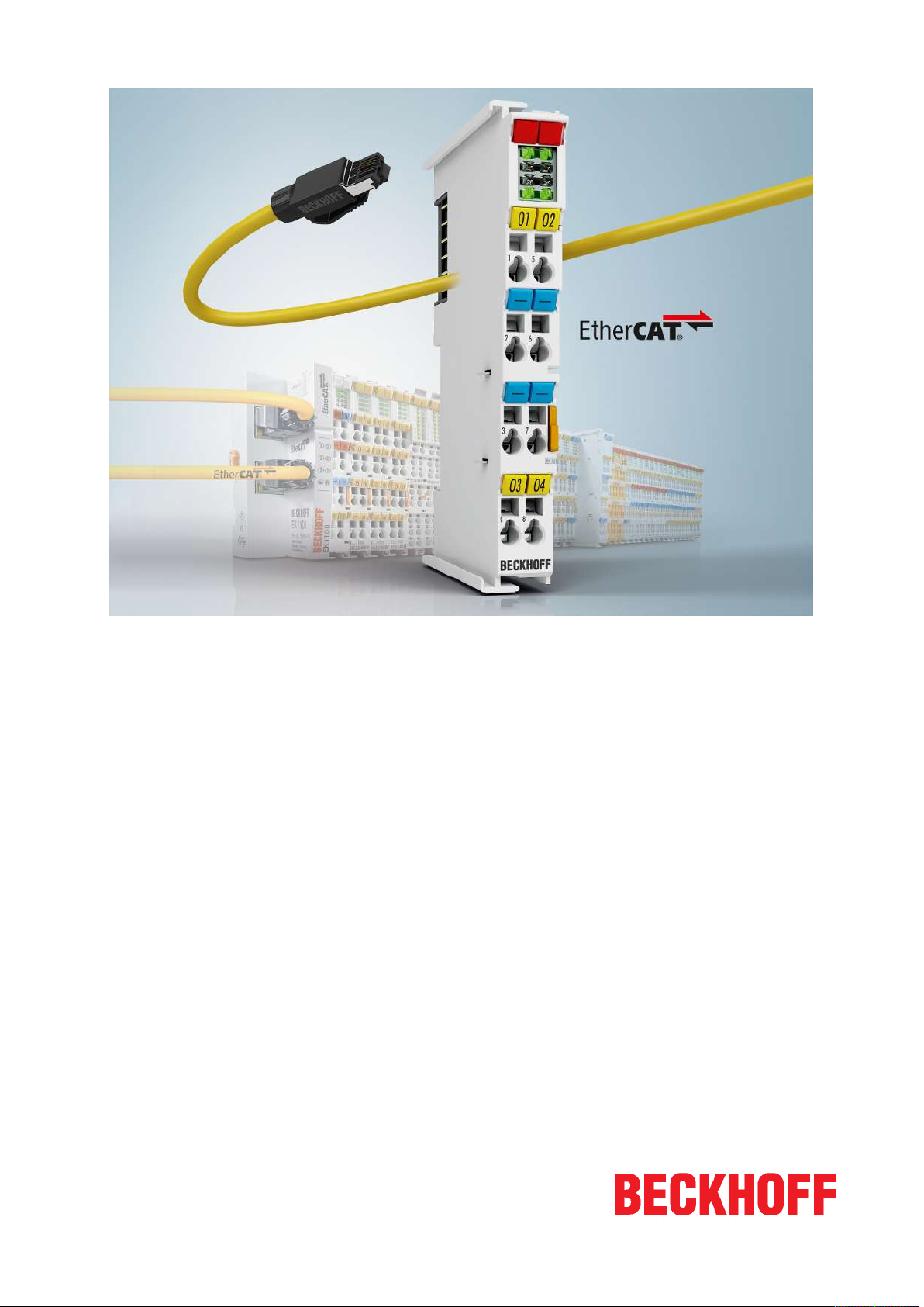
From 2014/01 the revision is shown on the outside of the IP20 terminals, see Fig. “EL5021 EL terminal,
standard IP20 IO device with batch number and revision ID (since 2014/01)”.
• The type, version and revision are read as decimal numbers, even if they are technically saved in
hexadecimal.
Identification number
Beckhoff EtherCAT devices from the different lines have different kinds of identification numbers:
Production lot/batch number/serial number/date code/D number
The serial number for Beckhoff IO devices is usually the 8-digit number printed on the device or on a sticker.
The serial number indicates the configuration in delivery state and therefore refers to a whole production
batch, without distinguishing the individual modules of a batch.
Structure of the serial number: KKYYFFHH
KK - week of production (CW, calendar week)
YY - year of production
FF - firmware version
HH - hardware version
EL6601, EL66148 Version: 4.2
Page 9
Foreword
Example with
Ser. no.: 12063A02: 12 - production week 12 06 - production year 2006 3A - firmware version 3A 02 hardware version 02
Exceptions can occur in the IP67 area, where the following syntax can be used (see respective device
documentation):
Syntax: D ww yy x y z u
D - prefix designation
ww - calendar week
yy - year
x - firmware version of the bus PCB
y - hardware version of the bus PCB
z - firmware version of the I/O PCB
u - hardware version of the I/O PCB
Example: D.22081501 calendar week 22 of the year 2008 firmware version of bus PCB: 1 hardware version
of bus PCB: 5 firmware version of I/O PCB: 0 (no firmware necessary for this PCB) hardware version of I/O
PCB: 1
Unique serial number/ID, ID number
In addition, in some series each individual module has its own unique serial number.
See also the further documentation in the area
• IP67: EtherCAT Box
• Safety: TwinSafe
• Terminals with factory calibration certificate and other measuring terminals
Examples of markings
Fig.1: EL5021 EL terminal, standard IP20 IO device with serial/ batch number and revision ID (since
2014/01)
EL6601, EL6614 9Version: 4.2
Page 10
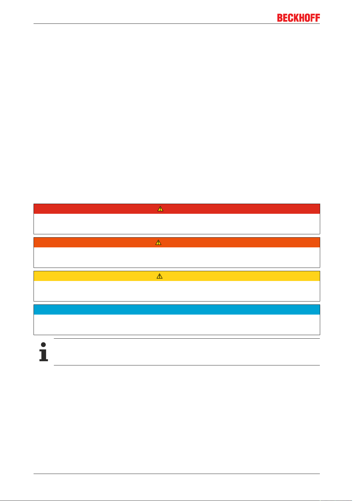
Foreword
Fig.2: EK1100 EtherCAT coupler, standard IP20 IO device with serial/ batch number
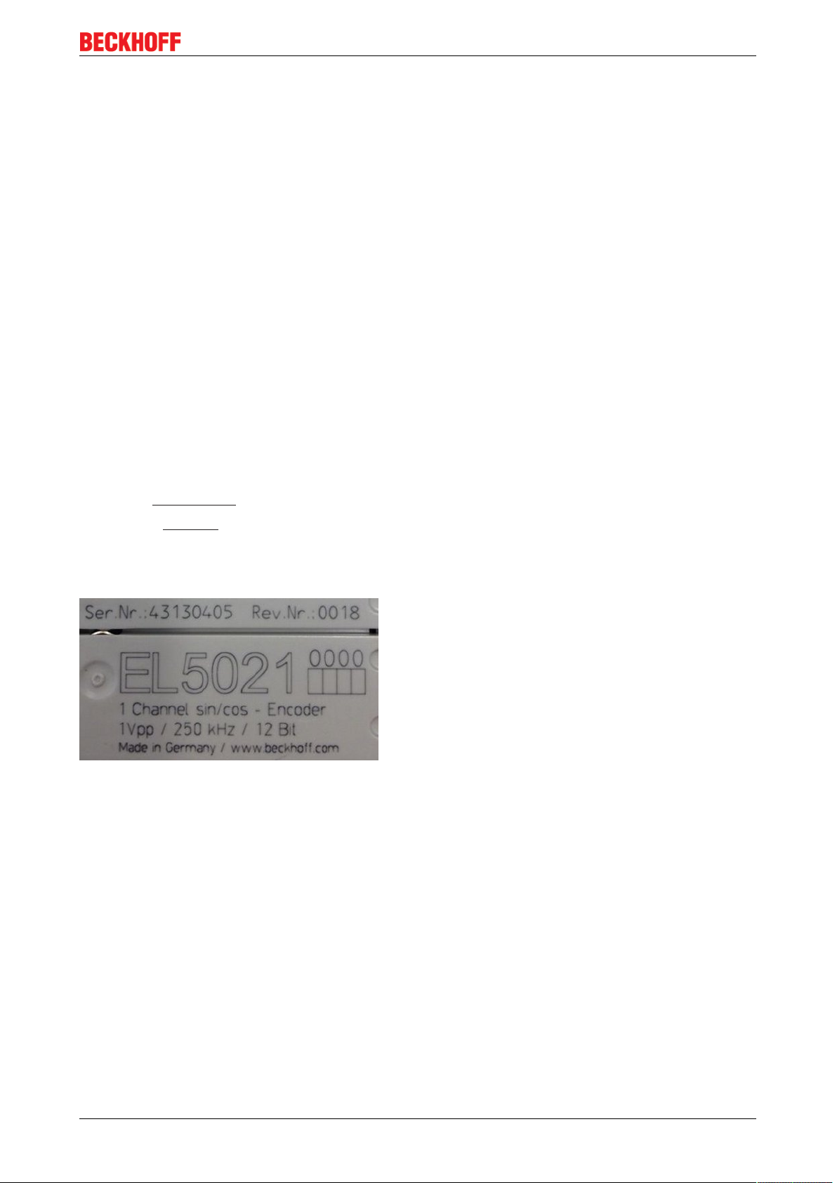
Fig.3: CU2016 switch with serial/ batch number
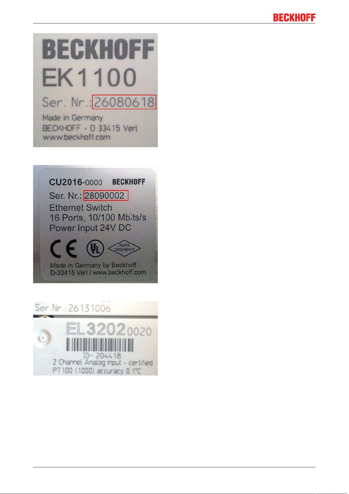
Fig.4: EL3202-0020 with serial/ batch number 26131006 and unique ID-number 204418
EL6601, EL661410 Version: 4.2
Page 11
Foreword
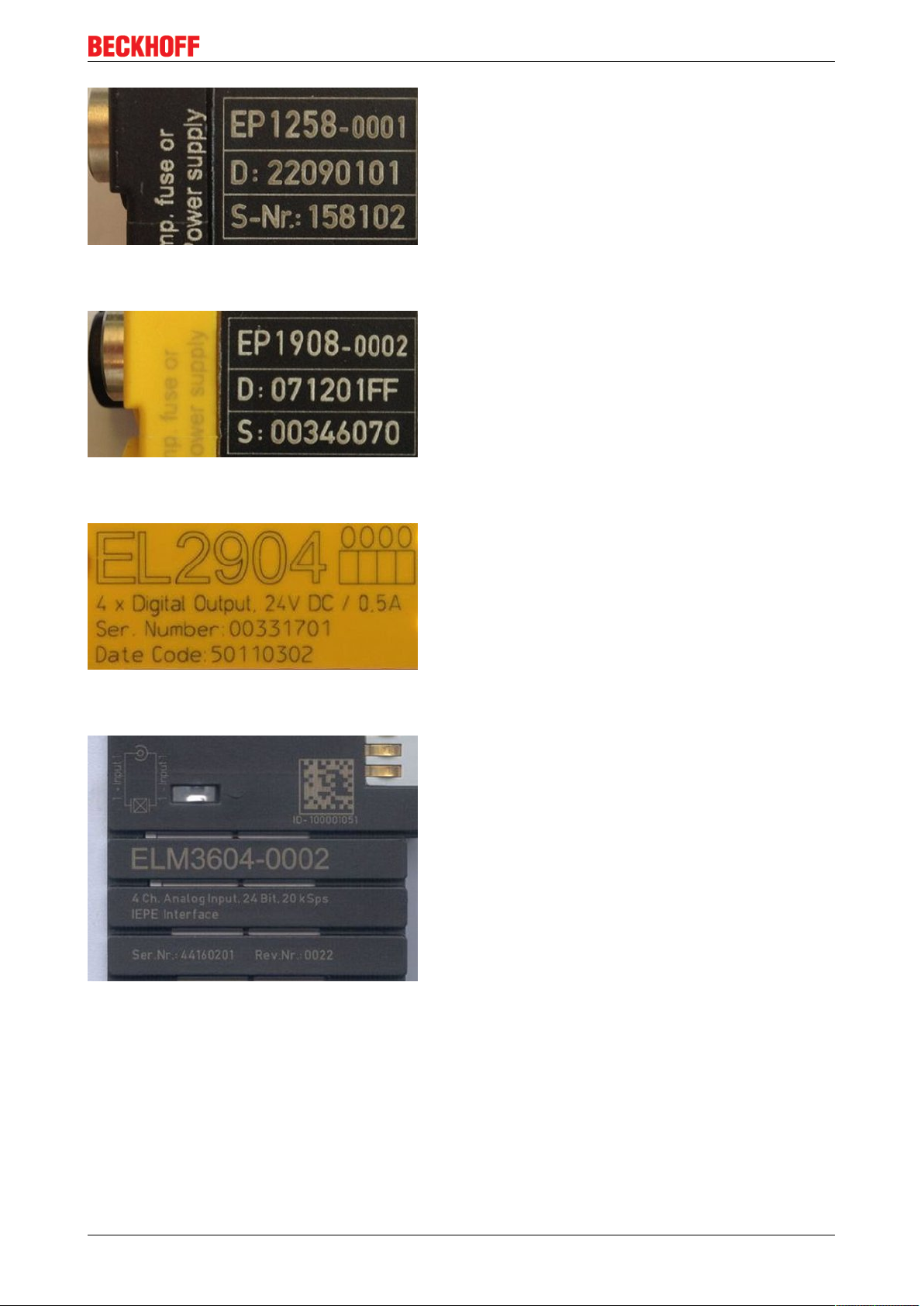
Fig.5: EP1258-00001 IP67 EtherCAT Box with batch number/ date code 22090101 and unique serial
number 158102
Fig.6: EP1908-0002 IP67 EtherCAT Safety Box with batch number/ date code 071201FF and unique serial
number 00346070
Fig.7: EL2904 IP20 safety terminal with batch number/ date code 50110302 and unique serial number
00331701
Fig.8: ELM3604-0002 terminal with unique ID number (QR code) 100001051 and serial/ batch number
44160201
EL6601, EL6614 11Version: 4.2
Page 12
Product overview
2 Product overview
2.1 Introduction
Fig.9: EL6601, EL6614
Switch terminals for Ethernet
The switch terminals for Ethernet are used for decentralized connection of random Ethernet devices to the
EtherCAT terminal network. The EtherCAT system relays the Ethernet communication of the connected
devices fully transparent and collision-free.
The 4 port Ethernet switch terminal EL6614 purposefully forwards the incoming frames from the ports to the
destination ports. In full duplex mode, it thus enables collision-free communication of the connected devices
with each other.
Any number of EL6601/EL6614 can be used simultaneously and at any position in the EtherCAT terminal
network. No configuration is required. In conjunction with the network port at the EtherCAT master the
EL6601/EL6614 devices operate like a virtual switch whose ports are distributed in the field. The EtherCAT
fieldbus is the backbone of this switch.
EL6601, EL661412 Version: 4.2
Page 13
Product overview
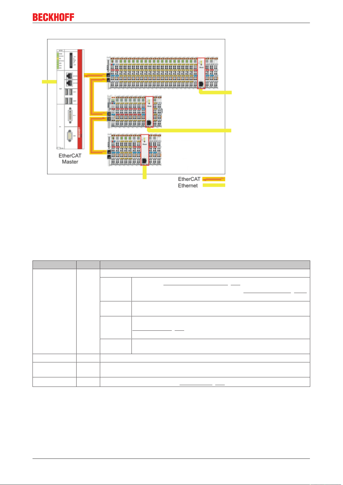
Fig.10: EL6601 as a virtual, field-distributed switch
Further benefits underline the particular suitability for the application in industrial environments:
• Compact design in EtherCAT terminal housing
• 10/100 MBaud, half or full duplex, with automatic baud rate detection
• Autocrossing (automatic detection of crossed lines)
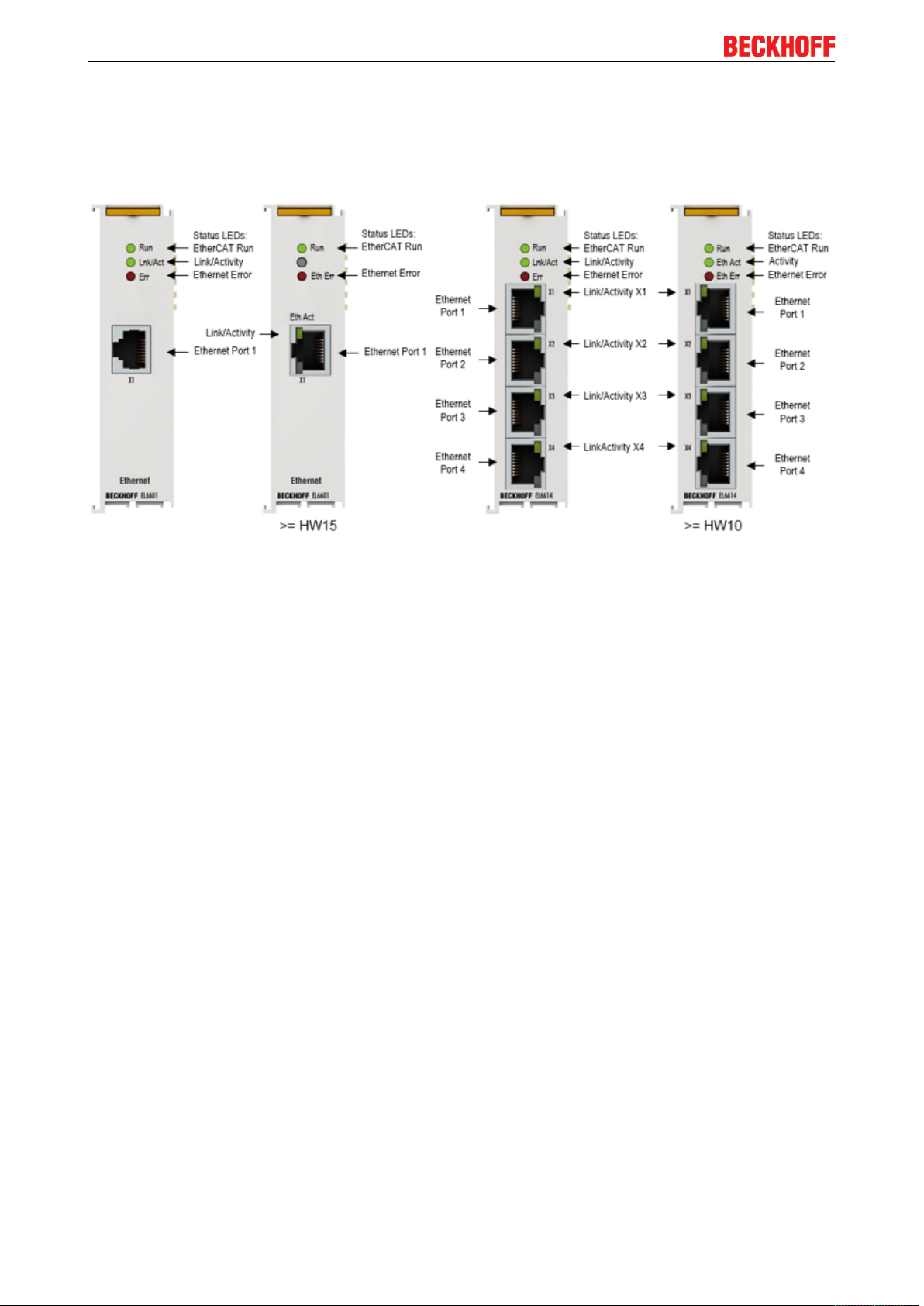
LEDs
LED Color Meaning
RUN green These LEDs indicate the terminal's operating state:
off
flashing State of the EtherCAT State Machine: PREOP = function for mailbox
single flash State of the EtherCAT State Machine: SAFEOP = verification of the
on State of the EtherCAT State Machine: OP = normal operating state;
Link/Act green Connection / data exchange field bus
*Link/Act X1 -X4green Connection / data exchange Ethernet port X1- X4
State of the EtherCAT State Machine [}73]: INIT = initialization of
the terminal or BOOTSTRAP = function for firmware updates [}146]
of the terminal
communication and different standard-settings set
Sync Manager [}74] channels and the distributed clocks.
Outputs remain in safe state
mailbox and process data communication is possible
Eth Err red
* only EL6614
Connections
1 x RJ45 with 10BASE-T/100BASE-TX Ethernet (EL6601)
4 x RJ45 with 10BASE-T/100BASE-TX Ethernet (EL6614)
EL6601, EL6614 13Version: 4.2
Error message EtherCAT (see Diagnostics [}16])
Page 14

Product overview
2.2 Technical data
Technical data EL6601 EL6614
Bus system all Ethernet (IEEE 802.3) based protocols
Number of Ethernet ports 1 4
Ethernet interface 10BASE-T/100BASE-TX
Ethernet with 1 x RJ45
Cable length up to 100 m twisted pair
Data transfer rate 10/100 Mbit/s, IEEE 802.3u Auto negotiation, half or full duplex at 10
and 100 Mbit/s possible, automatic settings
Network variables EL6601 as of Firmware 07, EL6614 as of Firmware 03:
max 32 Publishers with total of max. 1024 bytes total data [}22]
max 32 Subscriber with total of max. 1024 bytes total data [}22]
Distributed Clocks no
Diagnostics Status-LEDs, CoE data about ADS
Power supply via the E-bus
Current consumption via E-bus typ. 310 mA typ. 450 mA
Electrical isolation 500 V (E-Bus/Ethernet)
Bit width in process image -
Configuration TwinCAT System Manager/EtherCAT Master
Weight approx. 75 g approx. 85 g
Permissible ambient temperature
range during operation
-25°C ... +60°C (extended
temperature range)
10BASE-T/100BASE-TX Ethernet
with 4 x RJ45
Horizontal installation position:
-25°C ... +60°C (extended
temperature range)
all other installation positions:
-25°C ... + 45°C, see note [}46]
Permissible ambient temperature
range during storage
Permissible relative humidity 95%, no condensation
Dimensions (W x H x D) approx. 26 mm x 100 mm x 52 mm (width aligned: 23 mm)
Mounting on 35 mm mounting rail conforms to EN 60715
Vibration/shock resistance conforms to EN 60068-2-6 / EN 60068-2-27
EMC immunity/emission conforms to EN 61000-6-2 / EN 61000-6-4
Protection class IP20
Installation position variable
Approval CE
-40°C ... +85°C -40°C ... +85°C
see note [}46]
cULus [}144]
ATEX [}48]
2.3 Basic function principles
The EL66xx Ethernet Switchport terminals have 2 different operating modes, ideal for the tasks required for
Ethernet connectivity. The two operating modes, which can be active simultaneously, provide both the realtime-critical transmission and reception of configured network variables as well as the transport of standard
Ethernet traffic, which, while it is not real-time-critical, does involve large data flows using, for instance, the IP
protocol:
EL6601, EL661414 Version: 4.2
Page 15
Product overview
• Real-time data exchange: Publisher/subscriber, Beckhoff network variables, EtherCAT Automation
Protocol
The TwinCAT configuration file *.tsm configures an EL66xx when EtherCAT starts up with CoE
parameters in such a way that it
◦ transmits, as the publisher, data delivered through the cyclical data transfer in the real-time cycle.
◦ transmits subscribers received in the same way to the EtherCAT Master over the cyclical
EtherCAT data exchange.
Cyclical data exchange with the EL66xx is configured in the PDO settings of the EL66xx when
EtherCAT starts up, and cannot be changed online.
• Non-real-time data exchange
In parallel with this, the EL66xx can transfer Ethernet frames through the acyclic mailbox exchange
(EoE = Ethernet over EtherCAT) between the terminal and the EtherCAT Master/TwinCAT. This data
exchange is optimized for throughput, and may involve automatic fragmentation - by default, all
telegrams that are not transferred in the PDO context are transported through the acyclic channel by
means of EoE.
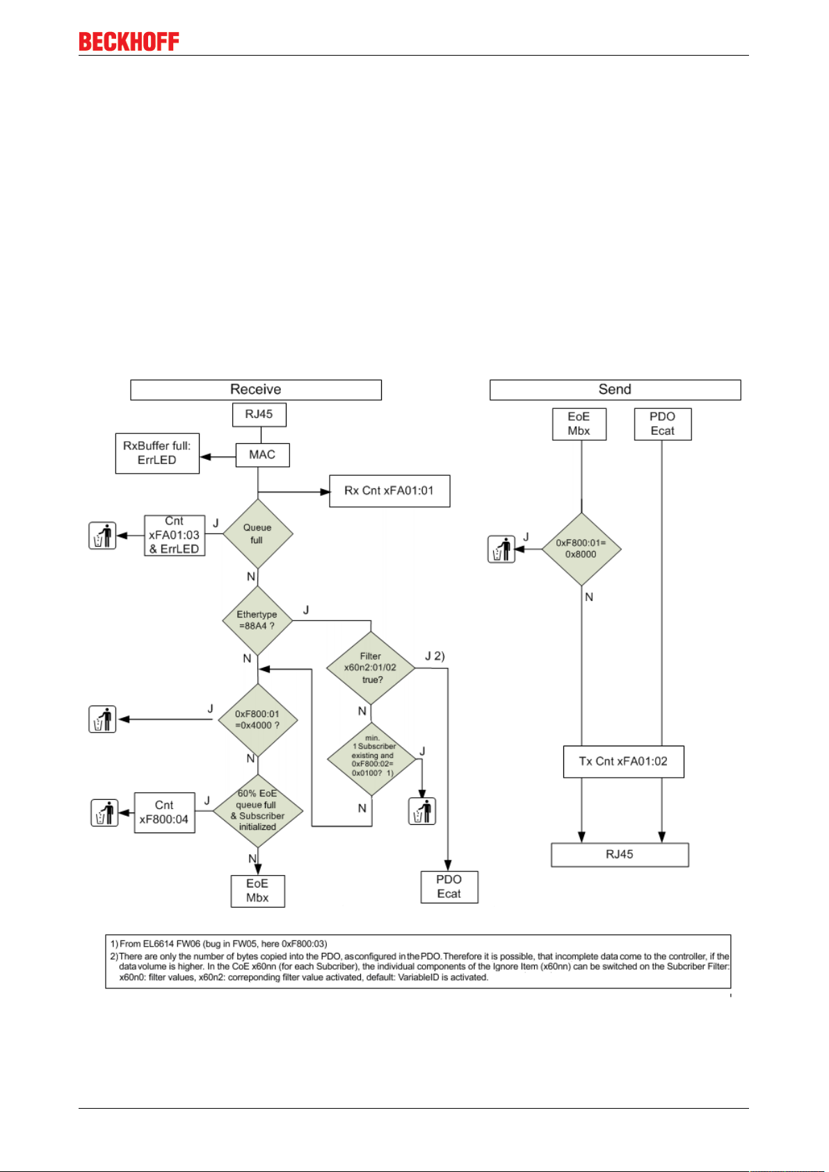
The flow of data in the EL66xx can be represented schematically as follows:
Fig.11: EL66xx data diagram
The EL6601/EL6614 cannot transport an EtherNet Industrial Protocol (EtherNet/IP).
EL6601, EL6614 15Version: 4.2
Page 16

Product overview
Diagnostics
Online diagnostics
The following objects are available for initial diagnostic in the CoE directory:
• 0xFA01, subindex 01: Frame Counter Rx (incoming to RJ45 socket).
• 0xFA01, subindex 02: Frame Counter Tx (outgoing from RJ45 socket).
The values can be read from the controller using PLC function blocks (FB_EcCoeSdoRead in
TcEtherCAT.lib).
This and further diagnostic information from the CoE of the EL66xx are accessible via https://
infosys.beckhoff.com/content/1033/el6601_el6614/Resources/zip/2349552907.zip .
Error LED
The red Error LED lights up 250 ms in the event of
• Ethernet Receive Overrun --> in general, more Ethernet frames are received at the RJ45 connection
than can be transported away via EtherCAT (PDO or mailbox). The telegrams are discarded.
• Ethernet EoE Overrun --> more non-real-time frames are being received at the RJ45 connector than
can be transported away by EtherCAT/EoE The data are discarded.
• Ethernet Frame Error
If the occurrence of an overrun causes data to be lost, higher protocol layers in an Ethernet network are
responsible for repeating the transmission.
Overruns
The following measures can be used to counter overruns:
• activating the Subscriber Filter [}22] in the EL66xx concerned
• Increasing/decelerating the cycle time of the publisher
• Suppressing temporarily publisher transmission or modulo in the System Manager
• Reducing/accelerating the EtherCAT cycle time of the subscriber, so that more data are fetched
by the EL66xx
Cable redundancy
If the EL66xx is operated in a system with cable redundancy, please keep the following in mind:
• real-time operation with network variables is possible
• in the event of non-real-time operation with IP transfer the IP traffic is routed via the primary EtherCAT
port. Therefore the Windows IP settings of this port are also used.
Fig.12: IP settings EtherCAT port
If there is no longer a link to this port, from Windows under TwinCAT 2 or 3 there is also no IP
communication to this port currently.
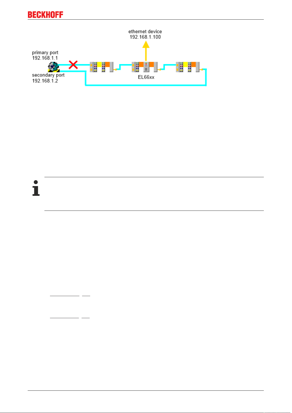
For this reason, do not let the Ethernet connection between the primary EtherCAT port and the first
EtherCAT slave fail, since otherwise IP communication is no longer possible via the EL66xx.
EL6601, EL661416 Version: 4.2
Page 17
Product overview
Fig.13: Connection failure between primary EtherCAT port and 1st slave (X)
2.4 EL66xx - Non Realtime
EL66xx and Ethernet transport via mailbox communication
In addition to regular cyclical process data exchange an EtherCAT master offers a further mechanism for
transporting data to an EtherCAT slave or reading data from it. This mechanism is used for one-time or
dynamically alternating Data Exchange, such as e.g. the parameterization of an EtherCAT slave. Mailbox
communication can also be used for transporting large data blocks acyclically on request from master or
slave. This additional communication takes place between the cyclical process data frames (the conventional
EtherCAT frames) on the EtherCAT bus.
Data throughput in mailbox communication
Since mailbox communication can only take place between the regular process data frames, data
throughput with this communication method depends on the load of the EtherCAT bus. This means
that the Ethernet throughput of the EL6601 also depends on the load of the underlying EtherCAT
fieldbus.
The EoE method (Ethernet over EtherCAT) is used for the EL66xx. Dedicated settings are available for this
in the System Manager.
Data throughput
The data throughput of the EL66xx in Ethernet frames or bytes/second depends on
• The EtherCAT cycle time on the fieldbus: The shorter the EtherCAT cycle used for the process data,
the more acyclical mailbox queries can be completed. If several different EtherCAT cycle times are
used in an EtherCAT strand the fastest cycle time is the relevant time
• The time between the process data frames that is available for mailbox communication: The longer the
Ethernet line is free for acyclical mailbox communication, the higher the Ethernet data throughput of the
EL6601.
• The mailbox size [}19] in bytes: The larger the mailbox, the more Ethernet frames the EL6601 can
send to the EtherCAT master or received from it simultaneously.
• The number of terminals in the EtherCAT system that use mailbox communication at the same time.
• The EoE settings [}21] in the TwinCAT System Manager, see the EoE section.
The following values were determined as samples (TwinCAT 2.10, 2.11)
• > 5 Mbit/s from the EL6601 to the Ethernet device
• > 2 Mbit/s from the Ethernet device to the EL6601
with an EtherCAT cycle time of 100 µs and a mailbox size of 1024 bytes.
EL6601, EL6614 17Version: 4.2
Page 18
Product overview
Tips for shortening the response times
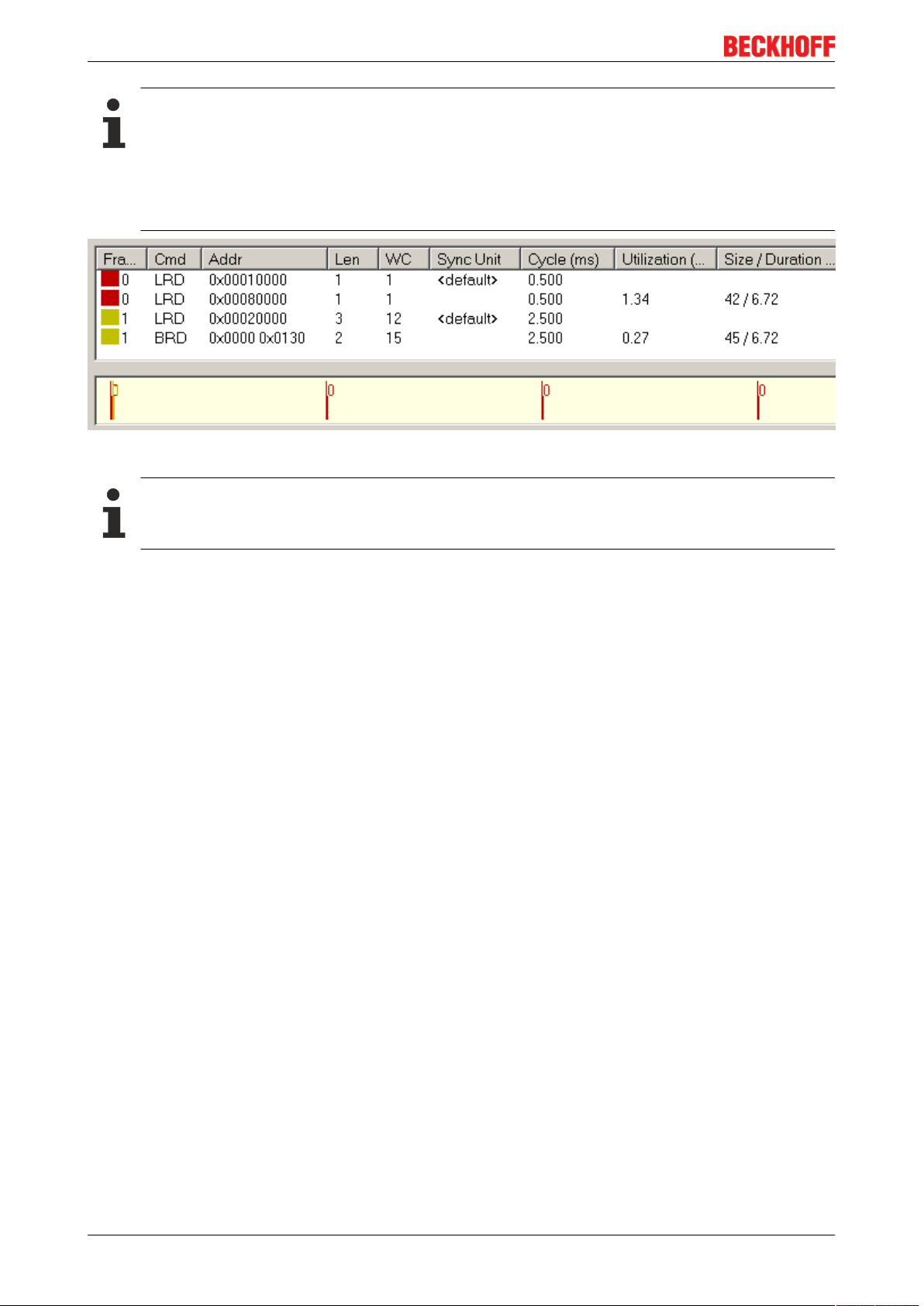
We recommend the following procedure to shorten the response times in your application (e.g. to
ping requests): Significantly lower the EtherCAT cycle time currently being used or insert a new task
with a lower cycle time, e.g.: 500µs if up to this point you have been using 2.5ms EtherCAT cycle.
Important: This task must access genuine IO process data from the EtherCAT slaves and be recognizable under Device EtherCAT -> Tab EtherCAT, see Fig. Real frame structure from the TwinCAT
System Manager
Fig.14: Real frame structure from the TwinCAT System Manager
Note regarding the specified values
These values are typical values without warranty. Throughput rates may differ in different applications depending on boundary conditions.
Address assignment
From FW03 onwards, the EL6601/6614 can also assign IP addresses to connected devices and works as a
DHCP or BOOTP server for one device. The following settings are required in the System Manager (EL66xx
--> Advanced Settings --> Mailbox --> EoE):
• Setting "Switch Port", Fig. Default setting of the EL66xx as switch port without IP address assignment.
The EL66xx works like a normal switch and passes Ethernet frames transparently through to TwinCAT/
Windows
• Setting for “IP Port”, Fig. From FW03: Settings for dynamically assigned IP address
The EL66xx works with address assignment to one connected Ethernet device. A DHCP or a BootP
Client must be activated in the device (refer to the network adaptor settings in the operating system).
The EL66xx responds to the device’s corresponding DHCP/BootP query by assigning the specified IP
address/subnet mask to the device. In the DHCP method this address is regularly queried by the client
and assigned to the server/EL66xx.
EL6601, EL661418 Version: 4.2
Page 19
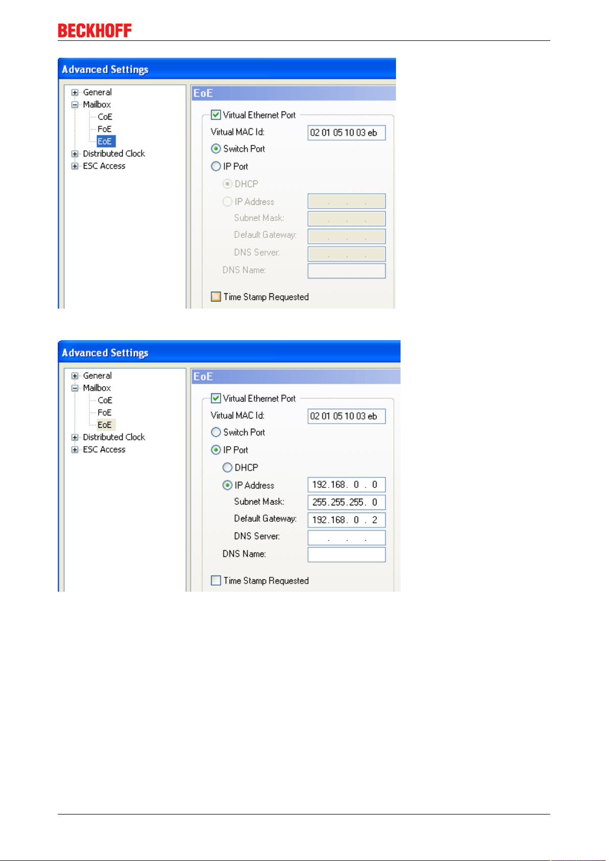
Fig.15: Default setting of the EL66xx as switch port without IP address assignment
Product overview
Fig.16: From FW03: Settings for dynamically assigned IP address
Please note:
• The “DHCP” checkbox must not be used - the “IP address” checkbox activates the DHCP/BootP
function in the EL66xx.
• The Gateway, Mask and Server settings are likewise communicated to the client/the device
• Only one address can be assigned, i.e. no switch with connected subscribers may follow.
• the address range must be identical to that of the EtherCAT adapter.
• DHCP Server Identifier: several DHCP Servers need a ServerID in the response telegram.
Solution for the EL6601 from firmware 15: the value 0x1000 has to be entered in the object 0xF800:01.
If a Default Gateway is registered in the EL6601, it is used as a DHCP Server Identifier.
Mailbox settings
The mailbox size can be modified in the Beckhoff TwinCAT System Manager:
EL6601, EL6614 19Version: 4.2
Page 20
Product overview
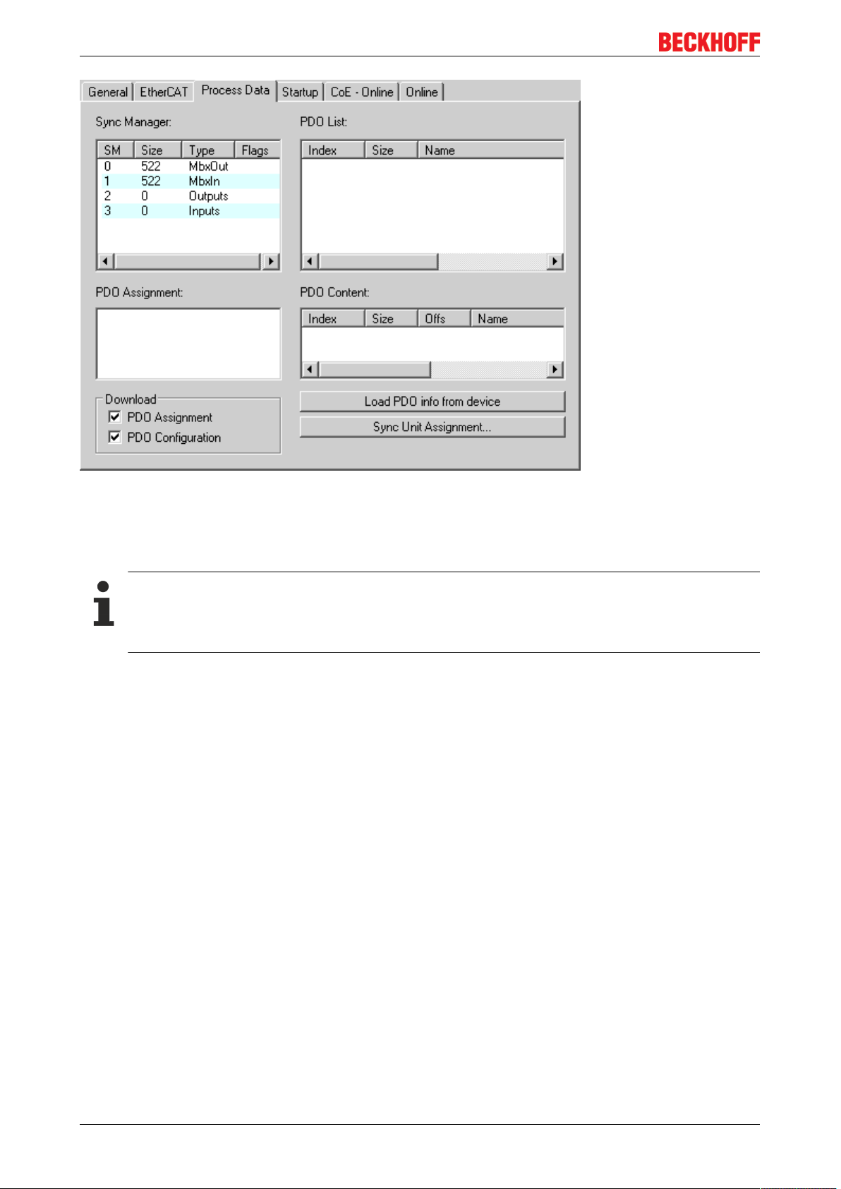
Fig.17: Default mailbox settings
By default the mailbox is set to 522Byte Input and 522Byte Output (20A
), see Fig. Default Settings of the
hex
Mailbox, Entries for SyncManager 0 and 1. To increase the data throughput the size of the mailbox can be
increased to 1024Byte, see Fig. Increasing the Size of the Mailbox.
Default mailbox size
As of Revision EL66xx-0000-0018 the mailbox is already set to 1024 Byte by default in both directions, therefore it cannot be further enlarged.
The previous statements apply for terminals with Revision -0000, -0016 or -0017.
EL6601, EL661420 Version: 4.2
Page 21
Product overview
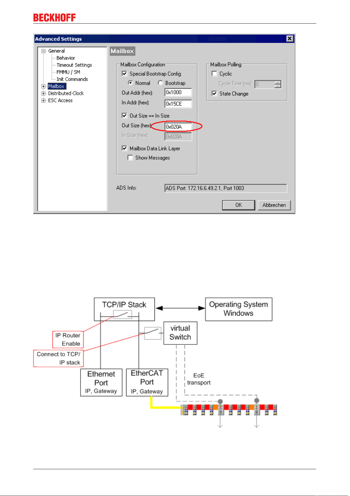
Fig.18: Increasing the mailbox
Under EL6601 -> EtherCAT tab -> "Advanced Settings…" -> "Mailbox" the "Out Size" can be set to
hexadecimal values between 42
dec
/2A
and 1024
hex
dec
/400
bytes. Ethernet frames that are larger than the
hex
EL6601 mailbox are fragmented by the EL6601 or the EtherCAT master and reassembled after passing
through the EtherCAT system.
Virtual switch setting
The EL66xx devices in the TwinCAT system generally appear as virtual switches, with the EtherCAT system
as the "backbone".
Fig.19: TwinCAT 2.11, virtual TwinCAT switch
The required settings will be found under TwinCAT | EtherCAT device | Advanced settings
EL6601, EL6614 21Version: 4.2
Page 22

Product overview
Fig.20: TwinCAT 2.11, virtual TwinCAT switch
Notes
• If a large number of EL66xx devices are used along the EtherCAT strand it may be helpful to increase
the value of MaxFrames
• If the EL66xx is used exclusively to transfer network variables, ConnectToTcpStack should be
deactivated
• IP-routing is active by default. This can also be checked by entering "ipconfig /all" on the command line
(Windows)
2.5 EL66xx and Beckhoff network variables
2.5.1 Explanation network variables
Network variables
The EL66xx support sending/receiving network variables. This applies for the EL6601 as of Firmware 07, for
the EL6614 as of Firmware 03.
A maximum of 32 for each, publishers and subscriber, are permitted per EL66xx.
Hardware replacement
If the system was designed with a previous EL6601 version (EL6601-0000-0000), this can be replaced with versions from EL6601-0000-0017 without problem. If the system was designed for version EL6601-0000-0017 or higher, replacement with a previous version is not possible due to unsupported network variables.
Network variables are specially configured Ethernet frames that enable Beckhoff devices to communicate
with each other in real-time via Ethernet. Such device can send (publisher) or receive (subscriber)
messages.
An Ethernet frame is sent for each publisher (Ethernet-based). A maximum of 1500 bytes of data can thus
be sent per publisher. Within a publisher/subscriber several variables (publisher and subscriber variables)
can be created.
Generally, several publishers/subscribers can be configured for each sending/receiving device (e.g. IPC or
EL6601).
Based on the sample of a data sender the hierarchy therefore consists of
• the sending device with a minimum of one Ethernet interface: IPC, CX, FC9011, EL6601, ...
EL6601, EL661422 Version: 4.2
Page 23

Product overview
◦ FastEthernet/100MBit and 1GBit are supported
◦ This Ethernet interface is configured in the local TwinCAT System Manager as a real-time
Ethernet device
• 1..n configured publishers - each publisher is sent as an independent Ethernet frame and can therefore
contain a maximum of 1500 bytes
• 1..n publisher variables contained therein for linking with the task/PLC
◦ For each publisher variable the user data and diagnostic data [}22] are transferred
On the receiver side the configuration is mirrored.
The EL66xx can also process publishers and subscribers which are frame data
• Max. 32 publishers and/or subscribers
• For each transmit direction (publisher or subscriber) the following maxima apply:
◦ all publishers: 1024 bytes total data [}22]
◦ all subscribers: 1024 bytes total data [}22]
Update of the terminal
The values above apply for a EL6601/6614-0000-0018. Version -0017 only supports a maximum of
300 bytes per publisher/subscriber. If a -0017 terminal is used, the values specified above can be
achieved by an update to revision -0018. Please contact our technical support.
With appropriate EtherCAT cycle time and depending on the scale and number of the publishers/subscribers
configured in the EL66xx, real-time cycle times down to 500 µs or below are possible.
Typical throughput values for EL6601, FW08, Rev. EL6601-0000-0018 are
• 1 publisher with 1000 bytes, 1 subscriber with 1000 bytes, simultaneous bidirectional operation: 2ms
• 1 publisher with 100 bytes, 1 subscriber with 100 bytes, simultaneous bidirectional operation: 300µs
Both characteristic values were determined with this https://infosys.beckhoff.com/content/1033/
el6601_el6614/Resources/zip/2349555083.zip . TwinCAT from version 2.11 is required for the *.tsm
System Manager file.
The EL6601 is used as a sample to explain configuration as publisher or subscriber for network variables.
The dialogs under TwinCAT 2.10 and TwinCAT 2.11 here are slightly different.
The following descriptions of the dialogs of the EL6601 in the TwinCAT System Manager can be applied
equally to the EL6614.
Note regarding the term total data
For each data direction the EL6601/EL6614 from Rev. -0018 can transfer a maximum of 1024 byte total
data. The total data consist of the user data (e.g. a UDINT) and the diagnostic data for the EL66xx.
Formula for number of diagnostic data bytes
• Publisher direction: 2 + ((number of publishers) * 2)
• Subscriber direction: 2 + ((number of subscriber variables) * 4)
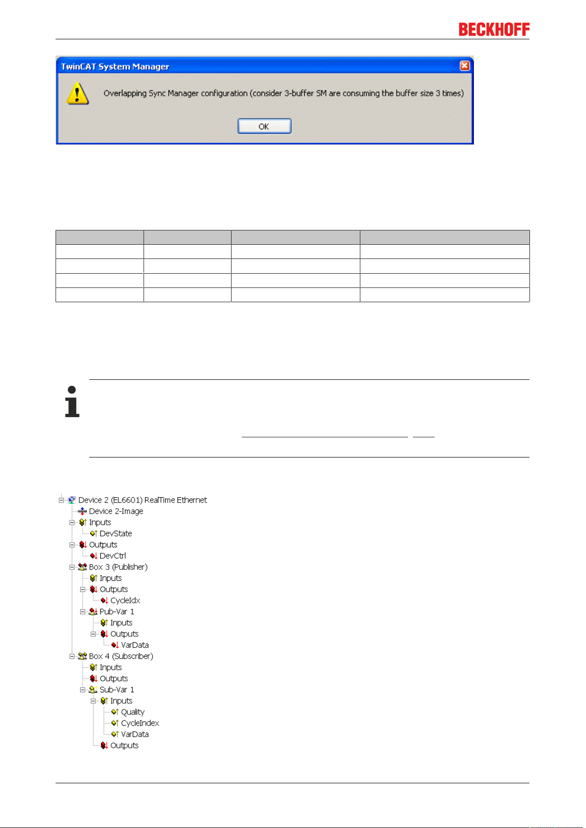
If the configured data quantity exceeds 1024 bytes, a corresponding message window appears when
activation is attempted:
EL6601, EL6614 23Version: 4.2
Page 24
Product overview
Fig.21: Notice on exceeding configured data volume
Note regarding the data quantity
The EL66xx (EL6601 from FW07, EL6614 from FW03) has an 8 kbyte data memory with the following
default allocation
Type Usable extent Operation mode Allocated memory
Mailbox Out 1024 bytes 1024 bytes (fixed)
Mailbox in 1024 bytes 1024 bytes (fixed)
Publisher 1024 bytes 3-buffer mode 3072 bytes
Subscriber 1024 bytes 3-buffer mode 3072 bytes
If more publisher or subscriber data are required for an application, the SyncManagers can be modified
accordingly. The mailbox cannot be modified.
2.5.2 Settings in the System Manager
Appearance of the variables
Depending on the platform used (PC or EL66xx), the publisher/subscriber will appear differently. A
publisher/subscriber can be created:
• on a PC network interface, see Beckhoff network variables - Settings [}105]
• on an EL66xx
The following sample illustrates the setup for a publisher and a subscriber variable (each with a size of a 16bit word) on an EL6601 under TwinCAT 2.10.
Fig.22: Network variable sample configuration on an EL6601
EL6601, EL661424 Version: 4.2
Page 25

Product overview
Process data:
• "CycleIdx": must be served by the application in order to be evaluated on the subscriber side
• "CycleIndex": CycleIdx counterpart on the subscriber side.
• "VarData": the data to be sent.
2.5.3 Notes
• The RT statistics displays are not supported under TwinCAT for an EL66xx-RT device.
Solution: As an alternative, corresponding CoE parameters can be read for diagnostic purposes.
• The publisher features of "OnChangeOnly" and "DataExchange (divider/modulo)" are not supported
together with the EL66xx.
Solution: [from FW08] Transmitting the configured publisher variables can be cyclically suppressed by
DevCtrl.
• If a publisher is set up on an EL66xx, the publisher's CycleIndex [}106] must be taken care of by the
user. On a PC, on the other hand, they are incremented by TwinCAT.
• The following is recommended for diagnosis of a network variable connection:
1. Monitor the link status in the "DevState" of the RT device (Device --> Inputs --> DevState). The
expected state is DevState = 0.
2. Monitor the Quality and CycleIndex in the subscriber.
• The link LED in the EL66xx only indicates the status of the cable connection, not that of any network
variable connection that may exist.
• If the EL66xx is used exclusively to transfer network variables, ConnectToTcpStack [}22] should be
deactivated.
• A maximum of 32 for each, publishers and subscriber, are permitted per EL66xx.
2.5.4 Suppress publisher
Applicable: TwinCAT from version 2.11, EL6601 from FW08, EL6614 from FW04
If the EL66xx is operated with a short cycle time and with publishers configured, this can place a high loading
on the connected network. For this reason, the EL66xx can be configured in such a way that the
transmission of individual publishers can be blocked through the DevCtrl variable. The object 0xF800:02
must be occupied in the CoE (CanOpenOverEtherCAT) for this purpose.
Groups of publisher boxes can be blocked by setting appropriate bits (publisher frames). The topmost 4 bits
(the high nibble of high byte) from 0xF800:02 specify the granularity of the groups 1..15, i.e. how many
publisher frames are handled together as one group:
The upper 8 bits of DevCtrl (format: 16 bits) then block the transmission of the publisher frames located in
the corresponding group in the current cycle.
High byte of DevCtrl :
• 0 = no blocking
• n = each bit in DevCtrl corresponds to a group of n publishers, where n has a value in the range [1..31]
It follows that a maximum of 8 groups of publishers can be blocked.
Sample:
DevCtrl.10 = true and 0xF800:02 = 0x2000 signifies that the third group will be blocked in this PLC cycle.
One group consists of 2 publisher frames, which means that in this case all the publisher variables that are
located in publisher frames 5 and 6 will not be transmitted.
EL6601, EL6614 25Version: 4.2
Page 26

Product overview
NOTE
Suppressing individual publishers
The structure of a "publisher" as a publisher box in the System Manager is
- an Ethernet frame containing
- n publishers
The individual bits in DevCtrl each block a group of publisher frames.
The success achieved in this way can be observed using, for instance, a network monitor such as
Wireshark.
Changes in the CoE
The CoE contents can, if writable, be changed online using the TwinCAT System Manager. However, after the terminal or the EtherCAT system is restarted, this change will no longer be present;
default values will apply. As a result, any permanent change must be stored in the terminal's CoE
startup list.
Note: In this documentation, bit counting starts from 0: value.0, value.1, ...
2.5.5 Filter subscribers
Applicable: TwinCAT from version 2.11, EL6601 from FW08, EL6614 from FW06
Depending on how the Ethernet network is configured, large or small numbers of the publisher telegrams
being used there arrive at the EL66xx devices included in the network. At the start, the EL 66xx is configured
by the EtherCAT Master to the subscriber variables that it is to receive: source AMS Net ID and ID of the
variables are loaded into the CoE for each subscriber. The CoE objects 0x60n0:01 and 0x60n0:02 then
respectively contain the AmsNetId and Variables ID to be checked. The EL66xx devices can therefore filter
according to the incoming publisher IDs, and compare them with their own subscriber IDs. For this purpose
the publisher variables contained in the Ethernet frames received are disassembled and checked
individually.
If an incoming subscriber
• corresponds to a configured AMS Net ID and Variables ID, then the contents are transferred to
EtherCAT via PDO.
• does NOT correspond to the above, then the contents are transferred as standard to the acyclic
mailbox interface for transmission to the Master.
This is the standard setting of the EL66xx.
The second way generates a high acyclic EtherCAT transport load, because subscribers received by the
EL66xx are transported that should not be transported by this EL66xx at all. For this reason the subscriber
filter can be activated by the CoE entry 0xF800:02 = 0x0100 (bit 8 = TRUE). The subscriber data that do
not correspond to the AmsNetID/Variables ID filter are then discarded in the terminal and are not transferred
to the mailbox.
Filter subscribers
Activation of the subscriber filter is recommended.
Since the EL66xx needs to be re-initialized with each INIT-OP transition, it is essential to set the
named CoE entry in the startup list.
Note: In this documentation, bit counting starts from 0: value.0, value.1, ...
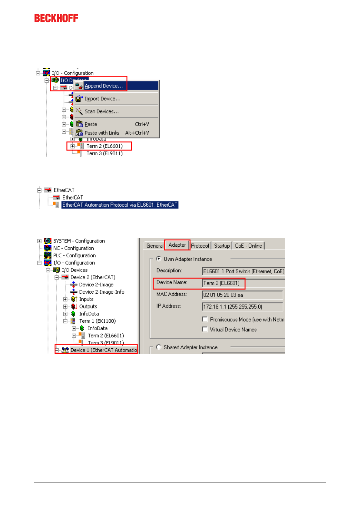
2.5.6 Setting up TwinCAT 2.10
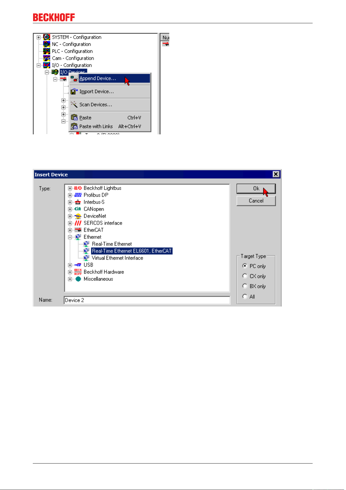
Once the EtherCAT bus and its devices have been configured, the EL6601 is appended as a separate
device in the configuration tree.
EL6601, EL661426 Version: 4.2
Page 27
Product overview
Fig.23: Append device
In the selection dialog an EL6601 is offered as a real-time Ethernet device. The EL6601 must also be
selected here when an EL6614 is being used.
Fig.24: Select EL6601
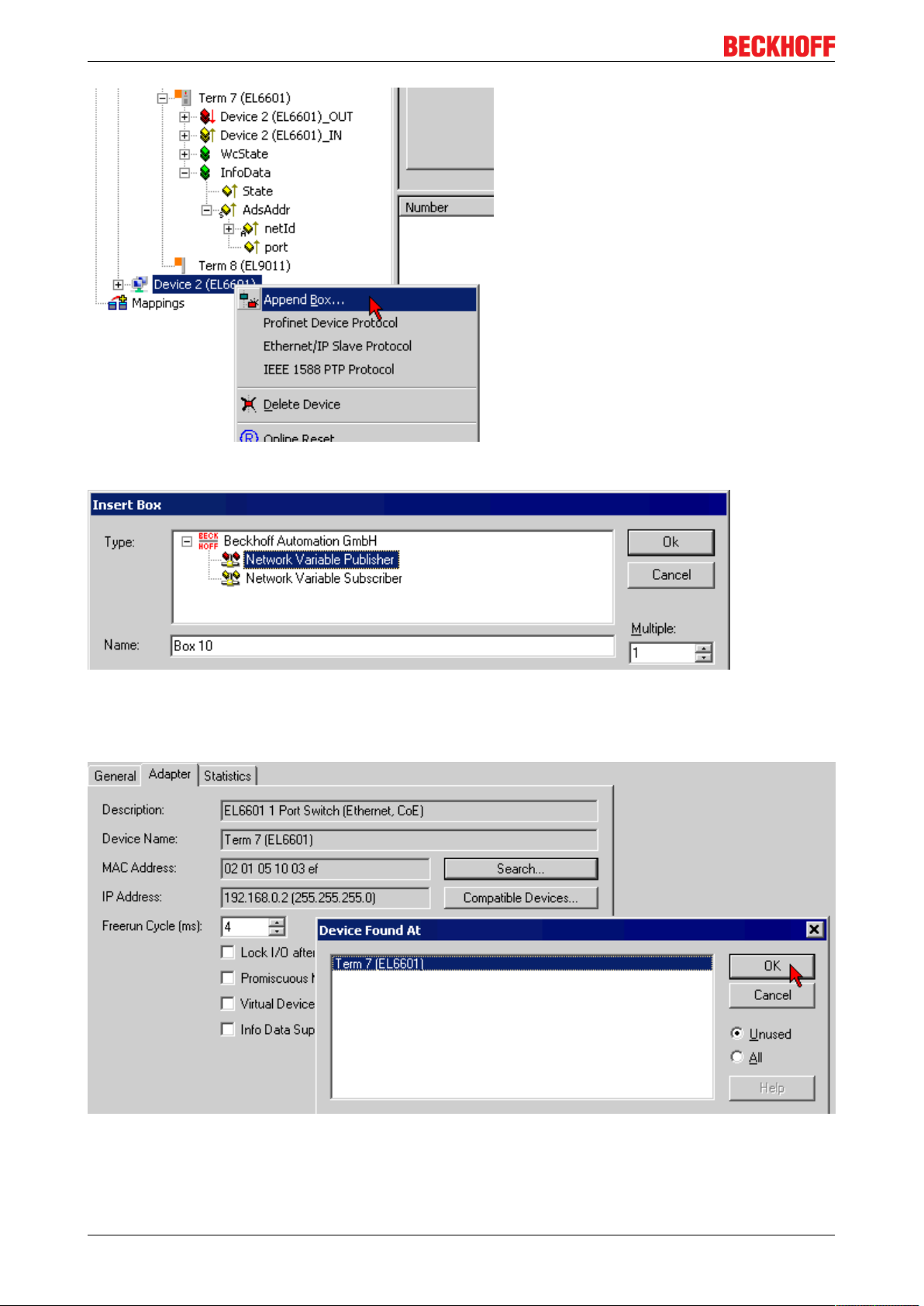
An imaginary box is now appended to the EL6601 as publisher or subscriber.
EL6601, EL6614 27Version: 4.2
Page 28
Product overview
Fig.25: Append box
Fig.26: Append network variable
The "EL6601 device" is now linked to the actual EL6601 or EL6614 in the selection dialog ("Adapter" tab ->
"Search...").
Fig.27: Link device with EL6601
All further steps are done as described in the preceding sections.
EL6601, EL661428 Version: 4.2
Page 29
Product overview
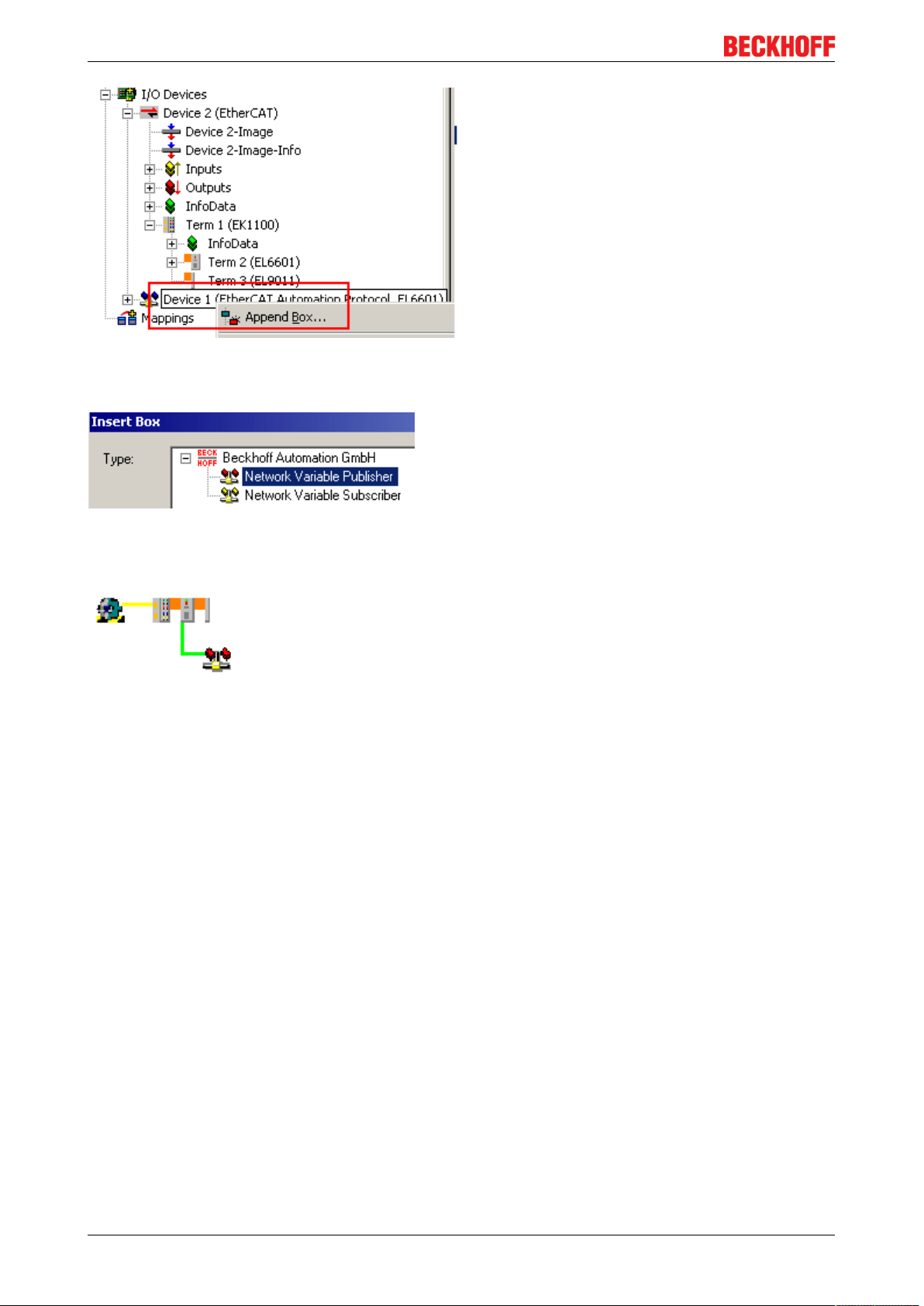
2.5.7 Setting up TwinCAT 2.11
If the EtherCAT configuration has been created manually or scanned from the field itself you can now
configure an EL66xx as a transmitter/receiver of network variables.
Fig.28: Append new device
Select the EtherCAT Automation Protocol in the device dialog:
Fig.29: Select EtherCAT Automation Protocol
The new device is automatically assigned to an available EL66xx, or this can also be done manually:
Fig.30: Device assignment to the EL66xx
Transmitter/receiver variables must now be created:
EL6601, EL6614 29Version: 4.2
Page 30
Product overview
Fig.31: Append box
Multiple publishers and subscribers can be created for each EtherCAT Automation Protocol device.
Fig.32: Publisher/Subscriber
An EtherCAT Automation Protocol device appears as follows in the topology view:
Fig.33: Topology view
All further steps are done as described in the preceding sections.
2.6 Configuration in the CX20x0 & CX50x0 system
The embedded PCs of CX20x0 and CX50x0 series feature a special integrated I/O interface for E-bus and
K-bus with automatic switching. The EL66xx devices in the TwinCAT system generally appear as virtual
switch, with the EtherCAT system as the "backbone". In the CX20x0 and CX50x0 system, the internal
interface connection is not implemented through a network interface, but through an FPGA.
EL6601, EL661430 Version: 4.2
Page 31

Product overview
Fig.34: Virtual TwinCAT switch in the CX20x0 & CX50x0 system
Due to the internal connection via FPGA and the automatic E-bus and K-bus detection, with offline
configuration the Ethernet port only becomes visible when the configuration is activated. To configure the
Ethernet port offline, proceed as follows:
• Due to the automatic E-bus and K-bus switching, any terminal should be connected with the
appropriate bus
• The internal PCI port is detected during offline configuration and must be selected
Fig.35: Dialog for selection of the PCI port
• The customer specified configuration can be created, and the EL66xx can be inserted in the
configuration
EL6601, EL6614 31Version: 4.2
Page 32

Product overview
Fig.36: Insertion of the EL66xx in the Configuration
• The Ethernet port is detected after "Reload I/O devices" (F4) and then appears under network
connections
• as "Local Area Connection 4"
Fig.37: New Network “Local Area Connection” in the Windows network connections
• The port can now be configured as required. The settings are applied and saved. Even if the port
disappears again, the settings are retained for subsequent commissioning.
If the problem persists, i.e. if the Ethernet port of the EL66xx still fails to show up in the network connection,
see troubleshooting tips below. Follow these tips and the countermeasures listed.
Prerequisites
Check the following:
Virtual Ethernet switch is not enabled
TwinCAT2 and TwinCAT3 are installed
simultaneously
Check the virtual switch settings [}21] and the
corresponding notes
Possible driver conflict, please contact Beckhoff support
EL6601, EL661432 Version: 4.2
Page 33

Basics communication
3 Basics communication
3.1 EtherCAT basics
Please refer to the EtherCAT System Documentation for the EtherCAT fieldbus basics.
3.2 EtherCAT cabling – wire-bound
The cable length between two EtherCAT devices must not exceed 100 m. This results from the FastEthernet
technology, which, above all for reasons of signal attenuation over the length of the cable, allows a maximum
link length of 5 + 90 + 5 m if cables with appropriate properties are used. See also the Design
recommendations for the infrastructure for EtherCAT/Ethernet.
Cables and connectors
For connecting EtherCAT devices only Ethernet connections (cables + plugs) that meet the requirements of
at least category 5 (CAt5) according to EN 50173 or ISO/IEC 11801 should be used. EtherCAT uses 4 wires
for signal transfer.
EtherCAT uses RJ45 plug connectors, for example. The pin assignment is compatible with the Ethernet
standard (ISO/IEC 8802-3).
Pin Color of conductor Signal Description
1 yellow TD + Transmission Data +
2 orange TD - Transmission Data -
3 white RD + Receiver Data +
6 blue RD - Receiver Data -
Due to automatic cable detection (auto-crossing) symmetric (1:1) or cross-over cables can be used between
EtherCAT devices from Beckhoff.
Recommended cables
Suitable cables for the connection of EtherCAT devices can be found on the Beckhoff website!
E-Bus supply
A bus coupler can supply the EL terminals added to it with the E-bus system voltage of 5V; a coupler is
thereby loadable up to 2A as a rule (see details in respective device documentation).
Information on how much current each EL terminal requires from the E-bus supply is available online and in
the catalogue. If the added terminals require more current than the coupler can supply, then power feed
terminals (e.g. EL9410) must be inserted at appropriate places in the terminal strand.
The pre-calculated theoretical maximum E-Bus current is displayed in the TwinCAT System Manager. A
shortfall is marked by a negative total amount and an exclamation mark; a power feed terminal is to be
placed before such a position.
EL6601, EL6614 33Version: 4.2
Page 34

Basics communication
Fig.38: System manager current calculation
NOTE
Malfunction possible!
The same ground potential must be used for the E-Bus supply of all EtherCAT terminals in a terminal block!
3.3 General notes for setting the watchdog
ELxxxx terminals are equipped with a safety feature (watchdog) that switches off the outputs after a
specifiable time e.g. in the event of an interruption of the process data traffic, depending on the device and
settings, e.g. in OFF state.
The EtherCAT slave controller (ESC) in the EL2xxx terminals features 2 watchdogs:
• SM watchdog (default: 100 ms)
• PDI watchdog (default: 100 ms)
SM watchdog (SyncManager Watchdog)
The SyncManager watchdog is reset after each successful EtherCAT process data communication with the
terminal. If no EtherCAT process data communication takes place with the terminal for longer than the set
and activated SM watchdog time, e.g. in the event of a line interruption, the watchdog is triggered and the
outputs are set to FALSE. The OP state of the terminal is unaffected. The watchdog is only reset after a
successful EtherCAT process data access. Set the monitoring time as described below.
The SyncManager watchdog monitors correct and timely process data communication with the ESC from the
EtherCAT side.
PDI watchdog (Process Data Watchdog)
If no PDI communication with the EtherCAT slave controller (ESC) takes place for longer than the set and
activated PDI watchdog time, this watchdog is triggered.
PDI (Process Data Interface) is the internal interface between the ESC and local processors in the EtherCAT
slave, for example. The PDI watchdog can be used to monitor this communication for failure.
The PDI watchdog monitors correct and timely process data communication with the ESC from the
application side.
The settings of the SM- and PDI-watchdog must be done for each slave separately in the TwinCAT System
Manager.
EL6601, EL661434 Version: 4.2
Page 35

Basics communication
Fig.39: EtherCAT tab -> Advanced Settings -> Behavior -> Watchdog
Notes:
• the multiplier is valid for both watchdogs.
• each watchdog has its own timer setting, the outcome of this in summary with the multiplier is a
resulting time.
• Important: the multiplier/timer setting is only loaded into the slave at the start up, if the checkbox is
activated.
If the checkbox is not activated, nothing is downloaded and the ESC settings remain unchanged.
Multiplier
Multiplier
Both watchdogs receive their pulses from the local terminal cycle, divided by the watchdog multiplier:
1/25 MHz * (watchdog multiplier + 2) = 100 µs (for default setting of 2498 for the multiplier)
The standard setting of 1000 for the SM watchdog corresponds to a release time of 100 ms.
The value in multiplier + 2 corresponds to the number of basic 40 ns ticks representing a watchdog tick.
The multiplier can be modified in order to adjust the watchdog time over a larger range.
EL6601, EL6614 35Version: 4.2
Page 36

Basics communication
Example "Set SM watchdog"
This checkbox enables manual setting of the watchdog times. If the outputs are set and the EtherCAT
communication is interrupted, the SM watchdog is triggered after the set time and the outputs are erased.
This setting can be used for adapting a terminal to a slower EtherCAT master or long cycle times. The
default SM watchdog setting is 100 ms. The setting range is 0..65535. Together with a multiplier with a range
of 1..65535 this covers a watchdog period between 0..~170 seconds.
Calculation
Multiplier = 2498 → watchdog base time = 1 / 25MHz * (2498 + 2) = 0.0001seconds = 100µs
SM watchdog = 10000 → 10000 * 100µs = 1second watchdog monitoring time
CAUTION
Undefined state possible!
The function for switching off of the SM watchdog via SM watchdog = 0 is only implemented in terminals
from version -0016. In previous versions this operating mode should not be used.
CAUTION
Damage of devices and undefined state possible!
If the SM watchdog is activated and a value of 0 is entered the watchdog switches off completely. This is
the deactivation of the watchdog! Set outputs are NOT set in a safe state, if the communication is interrupted.
3.4 EtherCAT State Machine
The state of the EtherCAT slave is controlled via the EtherCAT State Machine (ESM). Depending upon the
state, different functions are accessible or executable in the EtherCAT slave. Specific commands must be
sent by the EtherCAT master to the device in each state, particularly during the bootup of the slave.
A distinction is made between the following states:
• Init
• Pre-Operational
• Safe-Operational and
• Operational
• Boot
The regular state of each EtherCAT slave after bootup is the OP state.
EL6601, EL661436 Version: 4.2
Page 37

Fig.40: States of the EtherCAT State Machine
Basics communication
Init
After switch-on the EtherCAT slave in the Init state. No mailbox or process data communication is possible.
The EtherCAT master initializes sync manager channels 0 and 1 for mailbox communication.
Pre-Operational (Pre-Op)
During the transition between Init and Pre-Op the EtherCAT slave checks whether the mailbox was initialized
correctly.
In Pre-Op state mailbox communication is possible, but not process data communication. The EtherCAT
master initializes the sync manager channels for process data (from sync manager channel 2), the FMMU
channels and, if the slave supports configurable mapping, PDO mapping or the sync manager PDO
assignment. In this state the settings for the process data transfer and perhaps terminal-specific parameters
that may differ from the default settings are also transferred.
Safe-Operational (Safe-Op)
During transition between Pre-Op and Safe-Op the EtherCAT slave checks whether the sync manager
channels for process data communication and, if required, the distributed clocks settings are correct. Before
it acknowledges the change of state, the EtherCAT slave copies current input data into the associated DPRAM areas of the EtherCAT slave controller (ECSC).
In Safe-Op state mailbox and process data communication is possible, although the slave keeps its outputs
in a safe state, while the input data are updated cyclically.
Outputs in SAFEOP state
The default set watchdog [}34] monitoring sets the outputs of the module in a safe state - depending on the settings in SAFEOP and OP - e.g. in OFF state. If this is prevented by deactivation of the
watchdog monitoring in the module, the outputs can be switched or set also in the SAFEOP state.
Operational (Op)
Before the EtherCAT master switches the EtherCAT slave from Safe-Op to Op it must transfer valid output
data.
In the Op state the slave copies the output data of the masters to its outputs. Process data and mailbox
communication is possible.
EL6601, EL6614 37Version: 4.2
Page 38

Basics communication
Boot
In the Boot state the slave firmware can be updated. The Boot state can only be reached via the Init state.
In the Boot state mailbox communication via the file access over EtherCAT (FoE) protocol is possible, but no
other mailbox communication and no process data communication.
3.5 CoE Interface
General description
The CoE interface (CANopen over EtherCAT) is used for parameter management of EtherCAT devices.
EtherCAT slaves or the EtherCAT master manage fixed (read only) or variable parameters which they
require for operation, diagnostics or commissioning.
CoE parameters are arranged in a table hierarchy. In principle, the user has read access via the fieldbus.
The EtherCAT master (TwinCAT System Manager) can access the local CoE lists of the slaves via
EtherCAT in read or write mode, depending on the attributes.
Different CoE parameter types are possible, including string (text), integer numbers, Boolean values or larger
byte fields. They can be used to describe a wide range of features. Examples of such parameters include
manufacturer ID, serial number, process data settings, device name, calibration values for analog
measurement or passwords.
The order is specified in 2 levels via hexadecimal numbering: (main)index, followed by subindex. The value
ranges are
• Index: 0x0000 …0xFFFF (0...65535
• SubIndex: 0x00…0xFF (0...255
dez
)
dez
)
A parameter localized in this way is normally written as 0x8010:07, with preceding "x" to identify the
hexadecimal numerical range and a colon between index and subindex.
The relevant ranges for EtherCAT fieldbus users are:
• 0x1000: This is where fixed identity information for the device is stored, including name, manufacturer,
serial number etc., plus information about the current and available process data configurations.
• 0x8000: This is where the operational and functional parameters for all channels are stored, such as
filter settings or output frequency.
Other important ranges are:
• 0x4000: In some EtherCAT devices the channel parameters are stored here (as an alternative to the
0x8000 range).
• 0x6000: Input PDOs ("input" from the perspective of the EtherCAT master)
• 0x7000: Output PDOs ("output" from the perspective of the EtherCAT master)
Availability
Not every EtherCAT device must have a CoE list. Simple I/O modules without dedicated processor
usually have no variable parameters and therefore no CoE list.
If a device has a CoE list, it is shown in the TwinCAT System Manager as a separate tab with a listing of the
elements:
EL6601, EL661438 Version: 4.2
Page 39

Basics communication
Fig.41: "CoE Online " tab
The figure above shows the CoE objects available in device "EL2502", ranging from 0x1000 to 0x1600. The
subindices for 0x1018 are expanded.
Data management and function "NoCoeStorage"
Some parameters, particularly the setting parameters of the slave, are configurable and writeable. This can
be done in write or read mode
• via the System Manager (Fig. "CoE Online " tab) by clicking
This is useful for commissioning of the system/slaves. Click on the row of the index to be
parameterised and enter a value in the "SetValue" dialog.
• from the control system/PLC via ADS, e.g. through blocks from the TcEtherCAT.lib library
This is recommended for modifications while the system is running or if no System Manager or
operating staff are available.
Data management
If slave CoE parameters are modified online, Beckhoff devices store any changes in a fail-safe
manner in the EEPROM, i.e. the modified CoE parameters are still available after a restart.
The situation may be different with other manufacturers.
An EEPROM is subject to a limited lifetime with respect to write operations. From typically 100,000
write operations onwards it can no longer be guaranteed that new (changed) data are reliably saved
or are still readable. This is irrelevant for normal commissioning. However, if CoE parameters are
continuously changed via ADS at machine runtime, it is quite possible for the lifetime limit to be
reached. Support for the NoCoeStorage function, which suppresses the saving of changed CoE values, depends on the firmware version.
Please refer to the technical data in this documentation as to whether this applies to the respective
device.
• If the function is supported: the function is activated by entering the code word 0x12345678 once
in CoE 0xF008 and remains active as long as the code word is not changed. After switching the
device on it is then inactive. Changed CoE values are not saved in the EEPROM and can thus
be changed any number of times.
• Function is not supported: continuous changing of CoE values is not permissible in view of the
lifetime limit.
EL6601, EL6614 39Version: 4.2
Page 40

Basics communication
Startup list
Changes in the local CoE list of the terminal are lost if the terminal is replaced. If a terminal is replaced with a new Beckhoff terminal, it will have the default settings. It is therefore advisable to link
all changes in the CoE list of an EtherCAT slave with the Startup list of the slave, which is processed whenever the EtherCAT fieldbus is started. In this way a replacement EtherCAT slave can
automatically be parameterized with the specifications of the user.
If EtherCAT slaves are used which are unable to store local CoE values permanently, the Startup
list must be used.
Recommended approach for manual modification of CoE parameters
• Make the required change in the System Manager
The values are stored locally in the EtherCAT slave
• If the value is to be stored permanently, enter it in the Startup list.
The order of the Startup entries is usually irrelevant.
Fig.42: Startup list in the TwinCAT System Manager
The Startup list may already contain values that were configured by the System Manager based on the ESI
specifications. Additional application-specific entries can be created.
Online/offline list
While working with the TwinCAT System Manager, a distinction has to be made whether the EtherCAT
device is "available", i.e. switched on and linked via EtherCAT and therefore online, or whether a
configuration is created offline without connected slaves.
In both cases a CoE list as shown in Fig. “’CoE online’ tab” is displayed. The connectivity is shown as offline/
online.
• If the slave is offline
◦ The offline list from the ESI file is displayed. In this case modifications are not meaningful or
possible.
◦ The configured status is shown under Identity.
◦ No firmware or hardware version is displayed, since these are features of the physical device.
◦ Offline is shown in red.
EL6601, EL661440 Version: 4.2
Page 41

Basics communication
Fig.43: Offline list
• If the slave is online
◦ The actual current slave list is read. This may take several seconds, depending on the size and
cycle time.
◦ The actual identity is displayed
◦ The firmware and hardware version of the equipment according to the electronic information is
displayed
◦ Online is shown in green.
Fig.44: Online list
EL6601, EL6614 41Version: 4.2
Page 42

Basics communication
Channel-based order
The CoE list is available in EtherCAT devices that usually feature several functionally equivalent channels.
For example, a 4-channel analog 0..10 V input terminal also has 4 logical channels and therefore 4 identical
sets of parameter data for the channels. In order to avoid having to list each channel in the documentation,
the placeholder "n" tends to be used for the individual channel numbers.
In the CoE system 16 indices, each with 255 subindices, are generally sufficient for representing all channel
parameters. The channel-based order is therefore arranged in 16
dec
/10
steps. The parameter range
hex
0x8000 exemplifies this:
• Channel 0: parameter range 0x8000:00 ... 0x800F:255
• Channel 1: parameter range 0x8010:00 ... 0x801F:255
• Channel 2: parameter range 0x8020:00 ... 0x802F:255
• ...
This is generally written as 0x80n0.
Detailed information on the CoE interface can be found in the EtherCAT system documentation on the
Beckhoff website.
EL6601, EL661442 Version: 4.2
Page 43

Basics communication
3.6 Distributed Clock
The distributed clock represents a local clock in the EtherCAT slave controller (ESC) with the following
characteristics:
• Unit 1 ns
• Zero point 1.1.2000 00:00
• Size 64 bit (sufficient for the next 584 years; however, some EtherCAT slaves only offer 32-bit support,
i.e. the variable overflows after approx. 4.2 seconds)
• The EtherCAT master automatically synchronizes the local clock with the master clock in the EtherCAT
bus with a precision of < 100 ns.
For detailed information please refer to the EtherCAT system description.
EL6601, EL6614 43Version: 4.2
Page 44

Mounting and wiring
4 Mounting and wiring
4.1 Recommended mounting rails
Terminal Modules und EtherCAT Modules of KMxxxx and EMxxxx series, same as the terminals of the
EL66xx and EL67xx series can be snapped onto the following recommended mounting rails:
• DIN Rail TH35-7.5 with 1mm material thickness (according to EN60715)
• DIN Rail TH35-15 with 1,5mm material thickness
Pay attention to the material thickness of the DIN Rail
Terminal Modules und EtherCAT Modules of KMxxxx and EMxxxx series, same as the terminals of
the EL66xx and EL67xx seriesdoes not fit to the DIN Rail TH35-15 with 2,2 to 2,5mm material
thickness (according to EN60715)!
4.2 Mounting and demounting - terminals with front unlocking
The terminal modules are fastened to the assembly surface with the aid of a 35 mm mounting rail (e.g.
mounting rail TH 35-15).
Fixing of mounting rails
The locking mechanism of the terminals and couplers extends to the profile of the mounting rail. At
the installation, the locking mechanism of the components must not come into conflict with the fixing
bolts of the mounting rail. To mount the recommended mounting rails under the terminals and couplers, you should use flat mounting connections (e.g. countersunk screws or blind rivets).
WARNING
Risk of electric shock and damage of device!
Bring the bus terminal system into a safe, powered down state before starting installation, disassembly or
wiring of the Bus Terminals!
Mounting
• Fit the mounting rail to the planned assembly location.
and press (1) the terminal module against the mounting rail until it latches in place on the mounting
rail (2).
EL6601, EL661444 Version: 4.2
Page 45

Mounting and wiring
• Attach the cables.
Demounting
• Remove all the cables.
• Lever the unlatching hook back with thumb and forefinger (3). An internal mechanism pulls the two
latching lugs (3a) from the top hat rail back into the terminal module.
• Pull (4) the terminal module away from the mounting surface.
Avoid canting of the module; you should stabilize the module with the other hand, if required.
4.3 Positioning of passive Terminals
Hint for positioning of passive terminals in the bus terminal block
EtherCAT Terminals (ELxxxx / ESxxxx), which do not take an active part in data transfer within the
bus terminal block are so called passive terminals. The passive terminals have no current consumption out of the E-Bus.
To ensure an optimal data transfer, you must not directly string together more than 2 passive terminals!
EL6601, EL6614 45Version: 4.2
Page 46

Mounting and wiring
Examples for positioning of passive terminals (highlighted)
Fig.45: Correct positioning
Fig.46: Incorrect positioning
4.4 Installation positions
NOTE
Constraints regarding installation position and operating temperature range
Please refer to the technical data for a terminal to ascertain whether any restrictions regarding the installation position and/or the operating temperature range have been specified. When installing high power dissipation terminals ensure that an adequate spacing is maintained between other components above and below the terminal in order to guarantee adequate ventilation!
Optimum installation position (standard)
The optimum installation position requires the mounting rail to be installed horizontally and the connection
surfaces of the EL/KL terminals to face forward (see Fig. “Recommended distances for standard installation
position”). The terminals are ventilated from below, which enables optimum cooling of the electronics through
convection. "From below" is relative to the acceleration of gravity.
EL6601, EL661446 Version: 4.2
Page 47

Mounting and wiring
Fig.47: Recommended distances for standard installation position
Compliance with the distances shown in Fig. “Recommended distances for standard installation position” is
recommended.
Other installation positions
All other installation positions are characterized by different spatial arrangement of the mounting rail - see
Fig “Other installation positions”.
The minimum distances to ambient specified above also apply to these installation positions.
EL6601, EL6614 47Version: 4.2
Page 48

Mounting and wiring
Fig.48: Other installation positions
4.5 ATEX - Special conditions (extended temperature range)
WARNING
Observe the special conditions for the intended use of Beckhoff fieldbus components with
extended temperature range (ET) in potentially explosive areas (directive 94/9/EU)!
• The certified components are to be installed in a suitable housing that guarantees a protection class of at
least IP54 in accordance with EN 60529! The environmental conditions during use are thereby to be
taken into account!
• If the temperatures during rated operation are higher than 70°C at the feed-in points of cables, lines or
pipes, or higher than 80°C at the wire branching points, then cables must be selected whose temperature data correspond to the actual measured temperature values!
• Observe the permissible ambient temperature range of -25 to 60°C for the use of Beckhoff fieldbus components with extended temperature range (ET) in potentially explosive areas!
• Measures must be taken to protect against the rated operating voltage being exceeded by more than
40% due to short-term interference voltages!
• The individual terminals may only be unplugged or removed from the Bus Terminal system if the supply
voltage has been switched off or if a non-explosive atmosphere is ensured!
• The connections of the certified components may only be connected or disconnected if the supply voltage has been switched off or if a non-explosive atmosphere is ensured!
• The fuses of the KL92xx/EL92xx power feed terminals may only be exchanged if the supply voltage has
been switched off or if a non-explosive atmosphere is ensured!
• Address selectors and ID switches may only be adjusted if the supply voltage has been switched off or if
a non-explosive atmosphere is ensured!
Standards
The fundamental health and safety requirements are fulfilled by compliance with the following standards:
• EN 60079-0:2012+A11:2013
• EN 60079-15:2010
Marking
The Beckhoff fieldbus components with extended temperature range (ET) certified for potentially explosive
areas bear the following marking:
EL6601, EL661448 Version: 4.2
Page 49

II 3GKEMA 10ATEX0075 X Ex nA IIC T4 GcTa: -25…60°C
or
II 3GKEMA 10ATEX0075 X Ex nC IIC T4 GcTa: -25…60°C
4.6 ATEX Documentation
Notes about operation of the Beckhoff terminal systems in potentially explosive areas (ATEX)
Pay also attention to the continuative documentation
Notes about operation of the Beckhoff terminal systems in potentially explosive areas (ATEX)
that is available in the download area of the Beckhoff homepage http:\\www.beckhoff.com!
Mounting and wiring
EL6601, EL6614 49Version: 4.2
Page 50

Commissioning
5 Commissioning
5.1 TwinCAT Development Environment
The Software for automation TwinCAT (The Windows Control and Automation Technology) will be
distinguished into:
• TwinCAT2: System Manager (Configuration) & PLC Control (Programming)
• TwinCAT3: Enhancement of TwinCAT2 (Programming and Configuration takes place via a common
Development Environment)
Details:
• TwinCAT2:
◦ Connects I/O devices to tasks in a variable-oriented manner
◦ Connects tasks to tasks in a variable-oriented manner
◦ Supports units at the bit level
◦ Supports synchronous or asynchronous relationships
◦ Exchange of consistent data areas and process images
◦ Datalink on NT - Programs by open Microsoft Standards (OLE, OCX, ActiveX, DCOM+, etc.)
◦ Integration of IEC 61131-3-Software-SPS, Software- NC and Software-CNC within Windows
NT/2000/XP/Vista, Windows 7, NT/XP Embedded, CE
◦ Interconnection to all common fieldbusses
◦ More…
Additional features:
• TwinCAT3 (eXtended Automation):
◦ Visual-Studio®-Integration
◦ Choice of the programming language
◦ Supports object orientated extension of IEC 61131-3
◦ Usage of C/C++ as programming language for real time applications
◦ Connection to MATLAB®/Simulink®
◦ Open interface for expandability
◦ Flexible run-time environment
◦ Active support of Multi-Core- und 64-Bit-Operatingsystem
◦ Automatic code generation and project creation with the TwinCAT Automation Interface
◦ More…
Within the following sections commissioning of the TwinCAT Development Environment on a PC System for
the control and also the basically functions of unique control elements will be explained.
Please see further information to TwinCAT2 and TwinCAT3 at http://infosys.beckhoff.com.
5.1.1 Installation of the TwinCAT real-time driver
In order to assign real-time capability to a standard Ethernet port of an IPC controller, the Beckhoff real-time
driver has to be installed on this port under Windows.
This can be done in several ways. One option is described here.
In the System Manager call up the TwinCAT overview of the local network interfaces via Options → Show
Real Time Ethernet Compatible Devices.
EL6601, EL661450 Version: 4.2
Page 51

Fig.49: System Manager “Options” (TwinCAT2)
This have to be called up by the Menü “TwinCAT” within the TwinCAT3 environment:
Commissioning
Fig.50: Call up under VS Shell (TwinCAT3)
The following dialog appears:
Fig.51: Overview of network interfaces
Interfaces listed under “Compatible devices” can be assigned a driver via the “Install” button. A driver should
only be installed on compatible devices.
A Windows warning regarding the unsigned driver can be ignored.
Alternatively an EtherCAT-device can be inserted first of all as described in chapter Offline configuration
creation, section “Creating the EtherCAT device” [}60] in order to view the compatible ethernet ports via its
EtherCAT properties (tab „Adapter“, button „Compatible Devices…“):
EL6601, EL6614 51Version: 4.2
Page 52

Commissioning
Fig.52: EtherCAT device properties(TwinCAT2): click on „Compatible Devices…“ of tab “Adapter”
TwinCAT 3: the properties of the EtherCAT device can be opened by double click on “Device .. (EtherCAT)”
within the Solution Explorer under “I/O”:
After the installation the driver appears activated in the Windows overview for the network interface
(Windows Start → System Properties → Network)
Fig.53: Windows properties of the network interface
A correct setting of the driver could be:
EL6601, EL661452 Version: 4.2
Page 53

Fig.54: Exemplary correct driver setting for the Ethernet port
Other possible settings have to be avoided:
Commissioning
EL6601, EL6614 53Version: 4.2
Page 54

Commissioning
Fig.55: Incorrect driver settings for the Ethernet port
EL6601, EL661454 Version: 4.2
Page 55

IP address of the port used
IP address/DHCP
In most cases an Ethernet port that is configured as an EtherCAT device will not transport general
IP packets. For this reason and in cases where an EL6601 or similar devices are used it is useful to
specify a fixed IP address for this port via the “Internet Protocol TCP/IP” driver setting and to disable
DHCP. In this way the delay associated with the DHCP client for the Ethernet port assigning itself a
default IP address in the absence of a DHCP server is avoided. A suitable address space is
192.168.x.x, for example.
Commissioning
Fig.56: TCP/IP setting for the Ethernet port
EL6601, EL6614 55Version: 4.2
Page 56

Commissioning
5.1.2 Notes regarding ESI device description
Installation of the latest ESI device description
The TwinCAT EtherCAT master/System Manager needs the device description files for the devices to be
used in order to generate the configuration in online or offline mode. The device descriptions are contained
in the so-called ESI files (EtherCAT Slave Information) in XML format. These files can be requested from the
respective manufacturer and are made available for download. An *.xml file may contain several device
descriptions.
The ESI files for Beckhoff EtherCAT devices are available on the Beckhoff website.
The ESI files should be stored in the TwinCAT installation directory.
Default settings:
• TwinCAT2: C:\TwinCAT\IO\EtherCAT
• TwinCAT3: C:\TwinCAT\3.1\Config\Io\EtherCAT
The files are read (once) when a new System Manager window is opened, if they have changed since the
last time the System Manager window was opened.
A TwinCAT installation includes the set of Beckhoff ESI files that was current at the time when the TwinCAT
build was created.
For TwinCAT2.11/TwinCAT3 and higher, the ESI directory can be updated from the System Manager, if the
programming PC is connected to the Internet; by
• TwinCAT2: Option → “Update EtherCAT Device Descriptions”
• TwinCAT3: TwinCAT → EtherCAT Devices → “Update Device Descriptions (via ETG Website)…”
The TwinCAT ESI Updater is available for this purpose.
ESI
The *.xml files are associated with *.xsd files, which describe the structure of the ESI XML files. To
update the ESI device descriptions, both file types should therefore be updated.
Device differentiation
EtherCAT devices/slaves are distinguished by four properties, which determine the full device identifier. For
example, the device identifier EL2521-0025-1018 consists of:
• family key “EL”
• name “2521”
• type “0025”
• and revision “1018”
Fig.57: Identifier structure
The order identifier consisting of name + type (here: EL2521-0010) describes the device function. The
revision indicates the technical progress and is managed by Beckhoff. In principle, a device with a higher
revision can replace a device with a lower revision, unless specified otherwise, e.g. in the documentation.
Each revision has its own ESI description. See further notes [}8].
EL6601, EL661456 Version: 4.2
Page 57

Commissioning
Online description
If the EtherCAT configuration is created online through scanning of real devices (see section Online setup)
and no ESI descriptions are available for a slave (specified by name and revision) that was found, the
System Manager asks whether the description stored in the device should be used. In any case, the System
Manager needs this information for setting up the cyclic and acyclic communication with the slave correctly.
Fig.58: OnlineDescription information window (TwinCAT2)
In TwinCAT3 a similar window appears, which also offers the Web update:
Fig.59: Information window OnlineDescription (TwinCAT3)
If possible, the Yes is to be rejected and the required ESI is to be requested from the device manufacturer.
After installation of the XML/XSD file the configuration process should be repeated.
NOTE
Changing the ‘usual’ configuration through a scan
ü If a scan discovers a device that is not yet known to TwinCAT, distinction has to be made between two
cases. Taking the example here of the EL2521-0000 in the revision 1019
a) no ESI is present for the EL2521-0000 device at all, either for the revision 1019 or for an older revision.
The ESI must then be requested from the manufacturer (in this case Beckhoff).
b) an ESI is present for the EL2521-0000 device, but only in an older revision, e.g. 1018 or 1017.
In this case an in-house check should first be performed to determine whether the spare parts stock allows the integration of the increased revision into the configuration at all. A new/higher revision usually
also brings along new features. If these are not to be used, work can continue without reservations with
the previous revision 1018 in the configuration. This is also stated by the Beckhoff compatibility rule.
Refer in particular to the chapter ‘General notes on the use of Beckhoff EtherCAT IO components’ and for
manual configuration to the chapter ‘Offline configuration creation’ [}60].
If the OnlineDescription is used regardless, the System Manager reads a copy of the device description from
the EEPROM in the EtherCAT slave. In complex slaves the size of the EEPROM may not be sufficient for the
complete ESI, in which case the ESI would be incomplete in the configurator. Therefore it’s recommended
using an offline ESI file with priority in such a case.
The System Manager creates for online recorded device descriptions a new file
“OnlineDescription0000...xml” in its ESI directory, which contains all ESI descriptions that were read online.
EL6601, EL6614 57Version: 4.2
Page 58

Commissioning
Fig.60: File OnlineDescription.xml created by the System Manager
Is a slave desired to be added manually to the configuration at a later stage, online created slaves are
indicated by a prepended symbol “>” in the selection list (see Figure “Indication of an online recorded ESI of
EL2521 as an example”).
Fig.61: Indication of an online recorded ESI of EL2521 as an example
If such ESI files are used and the manufacturer's files become available later, the file OnlineDescription.xml
should be deleted as follows:
• close all System Manager windows
• restart TwinCAT in Config mode
• delete "OnlineDescription0000...xml"
• restart TwinCAT System Manager
This file should not be visible after this procedure, if necessary press <F5> to update
OnlineDescription for TwinCAT3.x
In addition to the file described above "OnlineDescription0000...xml" , a so called EtherCAT cache
with new discovered devices is created by TwinCAT3.x, e.g. under Windows 7:
(Please note the language settings of the OS!)
You have to delete this file, too.
Faulty ESI file
If an ESI file is faulty and the System Manager is unable to read it, the System Manager brings up an
information window.
Fig.62: Information window for faulty ESI file (left: TwinCAT2; right: TwinCAT3)
EL6601, EL661458 Version: 4.2
Page 59

Reasons may include:
• Structure of the *.xml does not correspond to the associated *.xsd file → check your schematics
• Contents cannot be translated into a device description → contact the file manufacturer
Commissioning
EL6601, EL6614 59Version: 4.2
Page 60

Commissioning
5.1.3 OFFLINE configuration creation
Creating the EtherCAT device
Create an EtherCAT device in an empty System Manager window.
Fig.63: Append EtherCAT device (left: TwinCAT2; right: TwinCAT3)
Select type ‘EtherCAT’ for an EtherCAT I/O application with EtherCAT slaves. For the present publisher/
subscriber service in combination with an EL6601/EL6614 terminal select “EtherCAT Automation Protocol
via EL6601”.
Fig.64: Selecting the EtherCAT connection (TwinCAT2.11, TwinCAT3)
Then assign a real Ethernet port to this virtual device in the runtime system.
Fig.65: Selecting the Ethernet port
This query may appear automatically when the EtherCAT device is created, or the assignment can be set/
modified later in the properties dialog; see Fig. “EtherCAT device properties (TwinCAT2)”.
EL6601, EL661460 Version: 4.2
Page 61

Commissioning
Fig.66: EtherCAT device properties (TwinCAT2)
TwinCAT 3: the properties of the EtherCAT device can be opened by double click on “Device .. (EtherCAT)”
within the Solution Explorer under “I/O”:
Selecting the Ethernet port
Ethernet ports can only be selected for EtherCAT devices for which the TwinCAT real-time driver is
installed. This has to be done separately for each port. Please refer to the respective installation
page [}50].
Defining EtherCAT slaves
Further devices can be appended by right-clicking on a device in the configuration tree.
Fig.67: Appending EtherCAT devices (left: TwinCAT2; right: TwinCAT3)
The dialog for selecting a new device opens. Only devices for which ESI files are available are displayed.
Only devices are offered for selection that can be appended to the previously selected device. Therefore the
physical layer available for this port is also displayed (Fig. “Selection dialog for new EtherCAT device”, A). In
the case of cable-based Fast-Ethernet physical layer with PHY transfer, then also only cable-based devices
are available, as shown in Fig. “Selection dialog for new EtherCAT device”. If the preceding device has
several free ports (e.g. EK1122 or EK1100), the required port can be selected on the right-hand side (A).
Overview of physical layer
• “Ethernet”: cable-based 100BASE-TX: EK couplers, EP boxes, devices with RJ45/M8/M12 connector
• “E-Bus”: LVDS “terminal bus”, “EJ-module”: EL/ES terminals, various modular modules
EL6601, EL6614 61Version: 4.2
Page 62

Commissioning
The search field facilitates finding specific devices (since TwinCAT2.11 or TwinCAT3).
Fig.68: Selection dialog for new EtherCAT device
By default only the name/device type is used as selection criterion. For selecting a specific revision of the
device the revision can be displayed as “Extended Information”.
Fig.69: Display of device revision
In many cases several device revisions were created for historic or functional reasons, e.g. through
technological advancement. For simplification purposes (see Fig. “Selection dialog for new EtherCAT
device”) only the last (i.e. highest) revision and therefore the latest state of production is displayed in the
selection dialog for Beckhoff devices. To show all device revisions available in the system as ESI
descriptions tick the “Show Hidden Devices” check box, see Fig. “Display of previous revisions”.
EL6601, EL661462 Version: 4.2
Page 63

Fig.70: Display of previous revisions
Device selection based on revision, compatibility
The ESI description also defines the process image, the communication type between master and
slave/device and the device functions, if applicable. The physical device (firmware, if available) has
to support the communication queries/settings of the master. This is backward compatible, i.e.
newer devices (higher revision) should be supported if the EtherCAT master addresses them as an
older revision. The following compatibility rule of thumb is to be assumed for Beckhoff EtherCAT
Terminals/ Boxes/ EJ-modules:
device revision in the system >= device revision in the configuration
This also enables subsequent replacement of devices without changing the configuration (different
specifications are possible for drives).
Commissioning
Example:
If an EL2521-0025-1018 is specified in the configuration, an EL2521-0025-1018 or higher (-1019, -1020) can
be used in practice.
Fig.71: Name/revision of the terminal
If current ESI descriptions are available in the TwinCAT system, the last revision offered in the selection
dialog matches the Beckhoff state of production. It is recommended to use the last device revision when
creating a new configuration, if current Beckhoff devices are used in the real application. Older revisions
should only be used if older devices from stock are to be used in the application.
In this case the process image of the device is shown in the configuration tree and can be parameterised as
follows: linking with the task, CoE/DC settings, plug-in definition, startup settings, ...
EL6601, EL6614 63Version: 4.2
Page 64

Commissioning
Fig.72: EtherCAT terminal in the TwinCAT tree (left: TwinCAT2; right: TwinCAT3)
EL6601, EL661464 Version: 4.2
Page 65

Commissioning
5.1.4 ONLINE configuration creation
Detecting/scanning of the EtherCAT device
The online device search can be used if the TwinCAT system is in CONFIG mode. This can be indicated by
a symbol right below in the information bar:
• on TwinCAT2 by a blue display “Config Mode” within the System Manager window: .
• on TwinCAT3 within the user interface of the development environment by a symbol .
TwinCAT can be set into this mode:
• TwinCAT2: by selection of in the Menubar or by “Actions” → “Set/Reset TwinCATtoConfig
Mode…”
• TwinCAT3: by selection of in the Menubar or by „TwinCAT“ → “RestartTwinCAT(ConfigMode)“
Online scanning in Config mode
The online search is not available in RUN mode (production operation). Note the differentiation between TwinCAT programming system and TwinCAT target system.
The TwinCAT2 icon ( ) or TwinCAT3 icon ( ) within the Windows-Taskbar always shows the
TwinCAT mode of the local IPC. Compared to that, the System Manager window of TwinCAT2 or the user
interface of TwinCAT3 indicates the state of the target system.
Fig.73: Differentiation local/target system (left: TwinCAT2; right: TwinCAT3)
Right-clicking on “I/O Devices” in the configuration tree opens the search dialog.
Fig.74: Scan Devices (left: TwinCAT2; right: TwinCAT3)
This scan mode attempts to find not only EtherCAT devices (or Ethernet ports that are usable as such), but
also NOVRAM, fieldbus cards, SMB etc. However, not all devices can be found automatically.
Fig.75: Note for automatic device scan (left: TwinCAT2; right: TwinCAT3)
EL6601, EL6614 65Version: 4.2
Page 66

Commissioning
Ethernet ports with installed TwinCAT real-time driver are shown as “RT Ethernet” devices. An EtherCAT
frame is sent to these ports for testing purposes. If the scan agent detects from the response that an
EtherCAT slave is connected, the port is immediately shown as an “EtherCAT Device” .
Fig.76: Detected Ethernet devices
Via respective checkboxes devices can be selected (as illustrated in Fig. “Detected Ethernet devices” e.g.
Device 3 and Device 4 were chosen). After confirmation with “OK” a device scan is suggested for all selected
devices, see Fig.: “Scan query after automatic creation of an EtherCAT device”.
Selecting the Ethernet port
Ethernet ports can only be selected for EtherCAT devices for which the TwinCAT real-time driver is
installed. This has to be done separately for each port. Please refer to the respective installation
page [}50].
Detecting/Scanning the EtherCAT devices
Online scan functionality
During a scan the master queries the identity information of the EtherCAT slaves from the slave
EEPROM. The name and revision are used for determining the type. The respective devices are located in the stored ESI data and integrated in the configuration tree in the default state defined
there.
Fig.77: Example default state
NOTE
Slave scanning in practice in series machine production
The scanning function should be used with care. It is a practical and fast tool for creating an initial configuration as a basis for commissioning. In series machine production or reproduction of the plant, however, the
function should no longer be used for the creation of the configuration, but if necessary for comparison
[}70] with the defined initial configuration.Background: since Beckhoff occasionally increases the revision
version of the delivered products for product maintenance reasons, a configuration can be created by such
a scan which (with an identical machine construction) is identical according to the device list; however, the
respective device revision may differ from the initial configuration.
Example:
Company A builds the prototype of a machine B, which is to be produced in series later on. To do this the
prototype is built, a scan of the IO devices is performed in TwinCAT and the initial configuration ‘B.tsm’ is
created. The EL2521-0025 EtherCAT terminal with the revision 1018 is located somewhere. It is thus built
into the TwinCAT configuration in this way:
EL6601, EL661466 Version: 4.2
Page 67

Commissioning
Fig.78: Installing EthetCAT terminal with revision -1018
Likewise, during the prototype test phase, the functions and properties of this terminal are tested by the
programmers/commissioning engineers and used if necessary, i.e. addressed from the PLC ‘B.pro’ or the
NC. (the same applies correspondingly to the TwinCAT3 solution files).
The prototype development is now completed and series production of machine B starts, for which Beckhoff
continues to supply the EL2521-0025-0018. If the commissioning engineers of the series machine production
department always carry out a scan, a B configuration with the identical contents results again for each
machine. Likewise, A might create spare parts stores worldwide for the coming series-produced machines
with EL2521-0025-1018 terminals.
After some time Beckhoff extends the EL2521-0025 by a new feature C. Therefore the FW is changed,
outwardly recognizable by a higher FW version and a new revision -1019. Nevertheless the new device
naturally supports functions and interfaces of the predecessor version(s); an adaptation of ‘B.tsm’ or even
‘B.pro’ is therefore unnecessary. The series-produced machines can continue to be built with ‘B.tsm’ and
‘B.pro’; it makes sense to perform a comparative scan [}70] against the initial configuration ‘B.tsm’ in order
to check the built machine.
However, if the series machine production department now doesn’t use ‘B.tsm’, but instead carries out a
scan to create the productive configuration, the revision -1019 is automatically detected and built into the
configuration:
Fig.79: Detection of EtherCAT terminal with revision -1019
This is usually not noticed by the commissioning engineers. TwinCAT cannot signal anything either, since
virtually a new configuration is created. According to the compatibility rule, however, this means that no
EL2521-0025-1018 should be built into this machine as a spare part (even if this nevertheless works in the
vast majority of cases).
In addition, it could be the case that, due to the development accompanying production in company A, the
new feature C of the EL2521-0025-1019 (for example, an improved analog filter or an additional process
data for the diagnosis) is discovered and used without in-house consultation. The previous stock of spare
part devices are then no longer to be used for the new configuration ‘B2.tsm’ created in this way.Þ if series
machine production is established, the scan should only be performed for informative purposes for
comparison with a defined initial configuration. Changes are to be made with care!
If an EtherCAT device was created in the configuration (manually or through a scan), the I/O field can be
scanned for devices/slaves.
Fig.80: Scan query after automatic creation of an EtherCAT device (left: TwinCAT2; right: TwinCAT3)
EL6601, EL6614 67Version: 4.2
Page 68

Commissioning
Fig.81: Manual triggering of a device scan on a specified EtherCAT device (left: TwinCAT2; right:
TwinCAT3)
In the System Manager (TwinCAT2) or the User Interface (TwinCAT3) the scan process can be monitored
via the progress bar at the bottom in the status bar.
Fig.82: Scan progressexemplary by TwinCAT2
The configuration is established and can then be switched to online state (OPERATIONAL).
Fig.83: Config/FreeRun query (left: TwinCAT2; right: TwinCAT3)
In Config/FreeRun mode the System Manager display alternates between blue and red, and the EtherCAT
device continues to operate with the idling cycle time of 4 ms (default setting), even without active task (NC,
PLC).
Fig.84: Displaying of “Free Run” and “Config Mode” toggling right below in the status bar
Fig.85: TwinCAT can also be switched to this state by using a button (left: TwinCAT2; right: TwinCAT3)
The EtherCAT system should then be in a functional cyclic state, as shown in Fig. “Online display example”.
EL6601, EL661468 Version: 4.2
Page 69

Commissioning
Fig.86: Online display example
Please note:
• all slaves should be in OP state
• the EtherCAT master should be in “Actual State” OP
• “frames/sec” should match the cycle time taking into account the sent number of frames
• no excessive “LostFrames” or CRC errors should occur
The configuration is now complete. It can be modified as described under manual procedure [}60].
Troubleshooting
Various effects may occur during scanning.
• An unknown device is detected, i.e. an EtherCAT slave for which no ESI XML description is available.
In this case the System Manager offers to read any ESI that may be stored in the device. This case is
described in the chapter "Notes regarding ESI device description".
• Device are not detected properly
Possible reasons include:
- faulty data links, resulting in data loss during the scan
- slave has invalid device description
The connections and devices should be checked in a targeted manner, e.g. via the emergency scan.
Then re-run the scan.
Fig.87: Faulty identification
In the System Manager such devices may be set up as EK0000 or unknown devices. Operation is not
possible or meaningful.
EL6601, EL6614 69Version: 4.2
Page 70

Commissioning
Scan over existing Configuration
NOTE
Change of the configuration after comparison
With this scan (TwinCAT2.11 or 3.1) only the device properties vendor (manufacturer), device name and
revision are compared at present! A ‘ChangeTo’ or ‘Copy’ should only be carried out with care, taking into
consideration the Beckhoff IO compatibility rule (see above). The device configuration is then replaced by
the revision found; this can affect the supported process data and functions.
If a scan is initiated for an existing configuration, the actual I/O environment may match the configuration
exactly or it may differ. This enables the configuration to be compared.
Fig.88: Identical configuration (left: TwinCAT2; right: TwinCAT3)
If differences are detected, they are shown in the correction dialog, so that the user can modify the
configuration as required.
Fig.89: Correction dialog
It is advisable to tick the “Extended Information” check box to reveal differences in the revision.
EL6601, EL661470 Version: 4.2
Page 71

Commissioning
Colour Explanation
green This EtherCAT slave matches the entry on the other side. Both type and revision match.
blue This EtherCAT slave is present on the other side, but in a different revision. This other
revision can have other default values for the process data as well as other/additional
functions.
If the found revision is higher than the configured revision, the slave may be used provided
compatibility issues are taken into account.
If the found revision is lower than the configured revision, it is likely that the slave cannot be
used. The found device may not support all functions that the master expects based on the
higher revision number.
light blue This EtherCAT slave is ignored (“Ignore” button)
red • This EtherCAT slave is not present on the other side.
• It is present, but in a different revision, which also differs in its properties from the one
specified.
The compatibility principle then also applies here: if the found revision is higher than the
configured revision, use is possible provided compatibility issues are taken into account,
since the successor devices should support the functions of the predecessor devices.
If the found revision is lower than the configured revision, it is likely that the slave cannot
be used. The found device may not support all functions that the master expects based on
the higher revision number.
Device selection based on revision, compatibility
The ESI description also defines the process image, the communication type between master and
slave/device and the device functions, if applicable. The physical device (firmware, if available) has
to support the communication queries/settings of the master. This is backward compatible, i.e.
newer devices (higher revision) should be supported if the EtherCAT master addresses them as an
older revision. The following compatibility rule of thumb is to be assumed for Beckhoff EtherCAT
Terminals/ Boxes/ EJ-modules:
device revision in the system >= device revision in the configuration
This also enables subsequent replacement of devices without changing the configuration (different
specifications are possible for drives).
Example:
If an EL2521-0025-1018 is specified in the configuration, an EL2521-0025-1018 or higher (-1019, -1020) can
be used in practice.
Fig.90: Name/revision of the terminal
If current ESI descriptions are available in the TwinCAT system, the last revision offered in the selection
dialog matches the Beckhoff state of production. It is recommended to use the last device revision when
creating a new configuration, if current Beckhoff devices are used in the real application. Older revisions
should only be used if older devices from stock are to be used in the application.
In this case the process image of the device is shown in the configuration tree and can be parameterised as
follows: linking with the task, CoE/DC settings, plug-in definition, startup settings, ...
EL6601, EL6614 71Version: 4.2
Page 72

Commissioning
Fig.91: Correction dialog with modifications
Once all modifications have been saved or accepted, click “OK” to transfer them to the real *.tsm
configuration.
Change to Compatible Type
TwinCAT offers a function “Change to Compatible Type…” for the exchange of a device whilst retaining the
links in the task.
Fig.92: Dialog “Change to Compatible Type…” (left: TwinCAT2; right: TwinCAT3)
This function is preferably to be used on AX5000 devices.
Change to Alternative Type
The TwinCAT System Manager offers a function for the exchange of a device: Change to Alternative Type
Fig.93: TwinCAT2 Dialog Change to Alternative Type
EL6601, EL661472 Version: 4.2
Page 73

Commissioning
If called, the System Manager searches in the procured device ESI (in this example: EL1202-0000) for
details of compatible devices contained there. The configuration is changed and the ESI-EEPROM is
overwritten at the same time – therefore this process is possible only in the online state (ConfigMode).
5.1.5 EtherCAT subscriber configuration
In the left-hand window of the TwinCAT2 System Manager or the Solution Explorer of the TwinCAT3
Development Environment respectively, click on the element of the terminal within the tree you wish to
configure (in the example: EL3751 Terminal 3).
Fig.94: Branch element as terminal EL3751
In the right-hand window of the TwinCAT System manager (TwinCAT2) or the Development Environment
(TwinCAT3), various tabs are now available for configuring the terminal. And yet the dimension of
complexity of a subscriber determines which tabs are provided. Thus as illustrated in the example above the
terminal EL3751 provides many setup options and also a respective number of tabs are available. On the
contrary by the terminal EL1004 for example the tabs "General", "EtherCAT", "Process Data" and “Online“
are available only. Several terminals, as for instance the EL6695 provide special functions by a tab with its
own terminal name, so “EL6695” in this case. A specific tab “Settings” by terminals with a wide range of
setup options will be provided also (e.g. EL3751).
„General“ tab
Fig.95: “General” tab
Name Name of the EtherCAT device
Id Number of the EtherCAT device
Type EtherCAT device type
Comment Here you can add a comment (e.g. regarding the
system).
Disabled Here you can deactivate the EtherCAT device.
Create symbols Access to this EtherCAT slave via ADS is only
available if this control box is activated.
EL6601, EL6614 73Version: 4.2
Page 74

Commissioning
„EtherCAT“ tab
Fig.96: „EtherCAT“ tab
Type EtherCAT device type
Product/Revision Product and revision number of the EtherCAT device
Auto Inc Addr. Auto increment address of the EtherCAT device. The
auto increment address can be used for addressing
each EtherCAT device in the communication ring
through its physical position. Auto increment
addressing is used during the start-up phase when
the EtherCAT master allocates addresses to the
EtherCAT devices. With auto increment addressing
the first EtherCAT slave in the ring has the address
0000
decremented by 1 (FFFF
. For each further slave the address is
hex
, FFFE
hex
hex
etc.).
EtherCAT Addr. Fixed address of an EtherCAT slave. This address is
allocated by the EtherCAT master during the start-up
phase. Tick the control box to the left of the input field
in order to modify the default value.
Previous Port Name and port of the EtherCAT device to which this
device is connected. If it is possible to connect this
device with another one without changing the order of
the EtherCAT devices in the communication ring,
then this combination field is activated and the
EtherCAT device to which this device is to be
connected can be selected.
Advanced Settings This button opens the dialogs for advanced settings.
The link at the bottom of the tab points to the product page for this EtherCAT device on the web.
“Process Data” tab
Indicates the configuration of the process data. The input and output data of the EtherCAT slave are
represented as CANopen process data objects (Process Data Objects, PDOs). The user can select a PDO
via PDO assignment and modify the content of the individual PDO via this dialog, if the EtherCAT slave
supports this function.
EL6601, EL661474 Version: 4.2
Page 75

Fig.97: “Process Data” tab
Commissioning
The process data (PDOs) transferred by an EtherCAT slave during each cycle are user data which the
application expects to be updated cyclically or which are sent to the slave. To this end the EtherCAT master
(Beckhoff TwinCAT) parameterizes each EtherCAT slave during the start-up phase to define which process
data (size in bits/bytes, source location, transmission type) it wants to transfer to or from this slave. Incorrect
configuration can prevent successful start-up of the slave.
For Beckhoff EtherCAT EL, ES, EM, EJ and EP slaves the following applies in general:
• The input/output process data supported by the device are defined by the manufacturer in the ESI/XML
description. The TwinCAT EtherCAT Master uses the ESI description to configure the slave correctly.
• The process data can be modified in the system manager. See the device documentation.
Examples of modifications include: mask out a channel, displaying additional cyclic information, 16-bit
display instead of 8-bit data size, etc.
• In so-called “intelligent” EtherCAT devices the process data information is also stored in the CoE
directory. Any changes in the CoE directory that lead to different PDO settings prevent successful
startup of the slave. It is not advisable to deviate from the designated process data, because the
device firmware (if available) is adapted to these PDO combinations.
If the device documentation allows modification of process data, proceed as follows (see Figure “Configuring
the process data”).
• A: select the device to configure
• B: in the “Process Data” tab select Input or Output under SyncManager (C)
• D: the PDOs can be selected or deselected
• H: the new process data are visible as linkable variables in the system manager
The new process data are active once the configuration has been activated and TwinCAT has been
restarted (or the EtherCAT master has been restarted)
• E: if a slave supports this, Input and Output PDO can be modified simultaneously by selecting a socalled PDO record (“predefined PDO settings”).
EL6601, EL6614 75Version: 4.2
Page 76

Commissioning
Fig.98: Configuring the process data
Manual modification of the process data
According to the ESI description, a PDO can be identified as “fixed” with the flag “F” in the PDO
overview (Fig. “Configuring the process data”, J). The configuration of such PDOs cannot be
changed, even if TwinCAT offers the associated dialog (“Edit”). In particular, CoE content cannot be
displayed as cyclic process data. This generally also applies in cases where a device supports
download of the PDO configuration, “G”. In case of incorrect configuration the EtherCAT slave usually refuses to start and change to OP state. The System Manager displays an “invalid SM cfg” logger message: This error message (“invalid SM IN cfg” or “invalid SM OUT cfg”) also indicates the
reason for the failed start.
A detailed description [}81] can be found at the end of this section.
„Startup“ tab
The Startup tab is displayed if the EtherCAT slave has a mailbox and supports the CANopen over EtherCAT
(CoE) or Servo drive over EtherCAT protocol. This tab indicates which download requests are sent to the
mailbox during startup. It is also possible to add new mailbox requests to the list display. The download
requests are sent to the slave in the same order as they are shown in the list.
EL6601, EL661476 Version: 4.2
Page 77

Fig.99: „Startup“ tab
Column Description
Transition Transition to which the request is sent. This can either be
• the transition from pre-operational to safe-operational (PS), or
• the transition from safe-operational to operational (SO).
If the transition is enclosed in "<>" (e.g. <PS>), the mailbox request is fixed and cannot be
modified or deleted by the user.
Protocol Type of mailbox protocol
Index Index of the object
Data Date on which this object is to be downloaded.
Comment Description of the request to be sent to the mailbox
Commissioning
Move Up This button moves the selected request up by one
position in the list.
Move Down This button moves the selected request down by one
position in the list.
New This button adds a new mailbox download request to
be sent during startup.
Delete This button deletes the selected entry.
Edit This button edits an existing request.
“CoE – Online” tab
The additional CoE - Online tab is displayed if the EtherCAT slave supports the CANopen over EtherCAT
(CoE) protocol. This dialog lists the content of the object list of the slave (SDO upload) and enables the user
to modify the content of an object from this list. Details for the objects of the individual EtherCAT devices can
be found in the device-specific object descriptions.
EL6601, EL6614 77Version: 4.2
Page 78

Commissioning
Fig.100: “CoE – Online” tab
Object list display
Column Description
Index Index and sub-index of the object
Name Name of the object
Flags RW The object can be read, and data can be written to the object (read/write)
RO The object can be read, but no data can be written to the object (read only)
P An additional P identifies the object as a process data object.
Value Value of the object
Update List The Update list button updates all objects in the displayed list
Auto Update If this check box is selected, the content of the objects is updated automatically.
Advanced The Advanced button opens the Advanced Settings dialog. Here you can specify
which objects are displayed in the list.
EL6601, EL661478 Version: 4.2
Page 79

Commissioning
Fig.101: Dialog “Advanced settings”
Online - via SDO Information If this option button is selected, the list of the objects included in the object
list of the slave is uploaded from the slave via SDO information. The list
below can be used to specify which object types are to be uploaded.
Offline - via EDS File If this option button is selected, the list of the objects included in the object
list is read from an EDS file provided by the user.
„Online“ tab
Fig.102: „Online“ tab
EL6601, EL6614 79Version: 4.2
Page 80

Commissioning
State Machine
Init This button attempts to set the EtherCAT device to the Init state.
Pre-Op This button attempts to set the EtherCAT device to the pre-operational state.
Op This button attempts to set the EtherCAT device to the operational state.
Bootstrap This button attempts to set the EtherCAT device to the Bootstrap state.
Safe-Op This button attempts to set the EtherCAT device to the safe-operational state.
Clear Error This button attempts to delete the fault display. If an EtherCAT slave fails during
change of state it sets an error flag.
Example: An EtherCAT slave is in PREOP state (pre-operational). The master now
requests the SAFEOP state (safe-operational). If the slave fails during change of state
it sets the error flag. The current state is now displayed as ERR PREOP. When the
Clear Error button is pressed the error flag is cleared, and the current state is
displayed as PREOP again.
Current State Indicates the current state of the EtherCAT device.
Requested State Indicates the state requested for the EtherCAT device.
DLL Status
Indicates the DLL status (data link layer status) of the individual ports of the EtherCAT slave. The DLL status
can have four different states:
Status Description
No Carrier / Open No carrier signal is available at the port, but the port is open.
No Carrier / Closed No carrier signal is available at the port, and the port is closed.
Carrier / Open A carrier signal is available at the port, and the port is open.
Carrier / Closed A carrier signal is available at the port, but the port is closed.
File Access over EtherCAT
Download With this button a file can be written to the EtherCAT device.
Upload With this button a file can be read from the EtherCAT device.
"DC" tab (Distributed Clocks)
Fig.103: "DC" tab (Distributed Clocks)
Operation Mode Options (optional):
• FreeRun
• SM-Synchron
• DC-Synchron (Input based)
• DC-Synchron
Advanced Settings… Advanced settings for readjustment of the real time determinant TwinCAT-
clock
Detailed information to Distributed Clocks are specified on http://infosys.beckhoff.com:
EL6601, EL661480 Version: 4.2
Page 81

Commissioning
Fieldbus Components → EtherCAT Terminals → EtherCAT System documentation → EtherCAT basics →
Distributed Clocks
5.1.5.1 Detailed description of Process Data tab
Sync Manager
Lists the configuration of the Sync Manager (SM).
If the EtherCAT device has a mailbox, SM0 is used for the mailbox output (MbxOut) and SM1 for the mailbox
input (MbxIn).
SM2 is used for the output process data (outputs) and SM3 (inputs) for the input process data.
If an input is selected, the corresponding PDO assignment is displayed in the PDO Assignment list below.
PDO Assignment
PDO assignment of the selected Sync Manager. All PDOs defined for this Sync Manager type are listed
here:
• If the output Sync Manager (outputs) is selected in the Sync Manager list, all RxPDOs are displayed.
• If the input Sync Manager (inputs) is selected in the Sync Manager list, all TxPDOs are displayed.
The selected entries are the PDOs involved in the process data transfer. In the tree diagram of the System
Manager these PDOs are displayed as variables of the EtherCAT device. The name of the variable is
identical to the Name parameter of the PDO, as displayed in the PDO list. If an entry in the PDO assignment
list is deactivated (not selected and greyed out), this indicates that the input is excluded from the PDO
assignment. In order to be able to select a greyed out PDO, the currently selected PDO has to be deselected
first.
Activation of PDO assignment
ü If you have changed the PDO assignment, in order to activate the new PDO assignment,
a) the EtherCAT slave has to run through the PS status transition cycle (from pre-operational to
safe-operational) once (see Online tab [}79]),
b) and the System Manager has to reload the EtherCAT slaves
( button for TwinCAT2 or button for TwinCAT3)
PDO list
List of all PDOs supported by this EtherCAT device. The content of the selected PDOs is displayed in the
PDO Content list. The PDO configuration can be modified by double-clicking on an entry.
Column Description
Index PDO index.
Size Size of the PDO in bytes.
Name Name of the PDO.
If this PDO is assigned to a Sync Manager, it appears as a variable of the slave with this
parameter as the name.
Flags F Fixed content: The content of this PDO is fixed and cannot be changed by the
System Manager.
M Mandatory PDO. This PDO is mandatory and must therefore be assigned to a
Sync Manager! Consequently, this PDO cannot be deleted from the PDO
Assignment list
SM Sync Manager to which this PDO is assigned. If this entry is empty, this PDO does not take
part in the process data traffic.
SU Sync unit to which this PDO is assigned.
EL6601, EL6614 81Version: 4.2
Page 82

Commissioning
PDO Content
Indicates the content of the PDO. If flag F (fixed content) of the PDO is not set the content can be modified.
Download
If the device is intelligent and has a mailbox, the configuration of the PDO and the PDO assignments can be
downloaded to the device. This is an optional feature that is not supported by all EtherCAT slaves.
PDO Assignment
If this check box is selected, the PDO assignment that is configured in the PDO Assignment list is
downloaded to the device on startup. The required commands to be sent to the device can be viewed in the
Startup [}76] tab.
PDO Configuration
If this check box is selected, the configuration of the respective PDOs (as shown in the PDO list and the
PDO Content display) is downloaded to the EtherCAT slave.
5.2 General Notes - EtherCAT Slave Application
This summary briefly deals with a number of aspects of EtherCAT Slave operation under TwinCAT. More
detailed information on this may be found in the corresponding sections of, for instance, the EtherCAT
System Documentation.
Diagnosis in real time: WorkingCounter, EtherCAT State and Status
Generally speaking an EtherCAT Slave provides a variety of diagnostic information that can be used by the
controlling task.
This diagnostic information relates to differing levels of communication. It therefore has a variety of sources,
and is also updated at various times.
Any application that relies on I/O data from a fieldbus being correct and up to date must make diagnostic
access to the corresponding underlying layers. EtherCAT and the TwinCAT System Manager offer
comprehensive diagnostic elements of this kind. Those diagnostic elements that are helpful to the controlling
task for diagnosis that is accurate for the current cycle when in operation (not during commissioning) are
discussed below.
Fig.104: Selection of the diagnostic information of an EtherCAT Slave
EL6601, EL661482 Version: 4.2
Page 83

Commissioning
In general, an EtherCAT Slave offers
• communication diagnosis typical for a slave (diagnosis of successful participation in the exchange of
process data, and correct operating mode)
This diagnosis is the same for all slaves.
as well as
• function diagnosis typical for a channel (device-dependent)
See the corresponding device documentation
The colors in Fig. “Selection of the diagnostic information of an EtherCAT Slave” also correspond to the
variable colors in the System Manager, see Fig. “Basic EtherCAT Slave Diagnosis in the PLC”.
Colour Meaning
yellow Input variables from the Slave to the EtherCAT Master, updated in every cycle
red Output variables from the Slave to the EtherCAT Master, updated in every cycle
green Information variables for the EtherCAT Master that are updated acyclically. This means that
it is possible that in any particular cycle they do not represent the latest possible status. It is
therefore useful to read such variables through ADS.
Fig. “Basic EtherCAT Slave Diagnosis in the PLC” shows an example of an implementation of basic
EtherCAT Slave Diagnosis. A Beckhoff EL3102 (2-channel analogue input terminal) is used here, as it offers
both the communication diagnosis typical of a slave and the functional diagnosis that is specific to a channel.
Structures are created as input variables in the PLC, each corresponding to the process image.
Fig.105: Basic EtherCAT Slave Diagnosis in the PLC
EL6601, EL6614 83Version: 4.2
Page 84

Commissioning
The following aspects are covered here:
Code Function Implementation Application/evaluation
A The EtherCAT Master's diagnostic infor-
mation
updated acyclically (yellow) or provided
acyclically (green).
B In the example chosen (EL3102) the
EL3102 comprises two analogue input
channels that transmit a single function
status for the most recent cycle.
C For every EtherCAT Slave that has cyclic
process data, the Master displays, using
what is known as a WorkingCounter,
whether the slave is participating successfully and without error in the cyclic exchange of process data. This important, elementary information is therefore provided
for the most recent cycle in the System
Manager
1. at the EtherCAT Slave, and, with
identical contents
2. as a collective variable at the
EtherCAT Master (see Point A)
for linking.
D Diagnostic information of the EtherCAT
Master which, while it is represented at the
slave for linking, is actually determined by
the Master for the Slave concerned and
represented there. This information cannot
be characterized as real-time, because it
• is only rarely/never changed,
except when the system starts up
• is itself determined acyclically (e.g.
EtherCAT Status)
Status
• the bit significations may be
found in the device
documentation
• other devices may supply
more information, or none
that is typical of a slave
WcState (Working Counter)
0: valid real-time communication in
the last cycle
1: invalid real-time communication
This may possibly have effects on
the process data of other Slaves
that are located in the same SyncUnit
State
current Status (INIT..OP) of the
Slave. The Slave must be in OP
(=8) when operating normally.
AdsAddr
The ADS address is useful for
communicating from the PLC/task
via ADS with the EtherCAT Slave,
e.g. for reading/writing to the CoE.
The AMS-NetID of a slave corresponds to the AMS-NetID of the
EtherCAT Master; communication
with the individual Slave is possible
via the port (= EtherCAT address).
At least the DevState is to be evaluated for
the most recent cycle in the PLC.
The EtherCAT Master's diagnostic information offers many more possibilities than are
treated in the EtherCAT System Documentation. A few keywords:
• CoE in the Master for communication
with/through the Slaves
• Functions from TcEtherCAT.lib
• Perform an OnlineScan
In order for the higher-level PLC task (or corresponding control applications) to be able to
rely on correct data, the function status must
be evaluated there. Such information is
therefore provided with the process data for
the most recent cycle.
In order for the higher-level PLC task (or corresponding control applications) to be able to
rely on correct data, the communication status of the EtherCAT Slave must be evaluated
there. Such information is therefore provided
with the process data for the most recent cycle.
Information variables for the EtherCAT Master that are updated acyclically. This means
that it is possible that in any particular cycle
they do not represent the latest possible status. It is therefore possible to read such variables through ADS.
NOTE
Diagnostic information
It is strongly recommended that the diagnostic information made available is evaluated so that the application can react accordingly.
CoE Parameter Directory
The CoE parameter directory (CanOpen-over-EtherCAT) is used to manage the set values for the slave
concerned. Changes may, in some circumstances, have to be made here when commissioning a relatively
complex EtherCAT Slave. It can be accessed through the TwinCAT System Manager, see Fig. “EL3102,
CoE directory”:
EL6601, EL661484 Version: 4.2
Page 85

Commissioning
Fig.106: EL3102, CoE directory
EtherCAT System Documentation
The comprehensive description in the EtherCAT System Documentation (EtherCAT Basics --> CoE
Interface) must be observed!
A few brief extracts:
• Whether changes in the online directory are saved locally in the slave depends on the device. EL
terminals (except the EL66xx) are able to save in this way.
• The user must manage the changes to the StartUp list.
Commissioning aid in the TwinCAT System Manager
Commissioning interfaces are being introduced as part of an ongoing process for EL/EP EtherCAT devices.
These are available in TwinCAT System Managers from TwinCAT 2.11R2 and above. They are integrated
into the System Manager through appropriately extended ESI configuration files.
EL6601, EL6614 85Version: 4.2
Page 86

Commissioning
Fig.107: Example of commissioning aid for a EL3204
This commissioning process simultaneously manages
• CoE Parameter Directory
• DC/FreeRun mode
• the available process data records (PDO)
Although the "Process Data", "DC", "Startup" and "CoE-Online" that used to be necessary for this are still
displayed, it is recommended that, if the commissioning aid is used, the automatically generated settings are
not changed by it.
The commissioning tool does not cover every possible application of an EL/EP device. If the available setting
options are not adequate, the user can make the DC, PDO and CoE settings manually, as in the past.
EtherCAT State: automatic default behaviour of the TwinCAT System Manager and manual operation
After the operating power is switched on, an EtherCAT Slave must go through the following statuses
• INIT
• PREOP
• SAFEOP
• OP
to ensure sound operation. The EtherCAT Master directs these statuses in accordance with the initialization
routines that are defined for commissioning the device by the ES/XML and user settings (Distributed Clocks
(DC), PDO, CoE). See also the section on "Principles of Communication, EtherCAT State Machine [}36]" in
this connection. Depending how much configuration has to be done, and on the overall communication,
booting can take up to a few seconds.
The EtherCAT Master itself must go through these routines when starting, until it has reached at least the
OP target state.
The target state wanted by the user, and which is brought about automatically at start-up by TwinCAT, can
be set in the System Manager. As soon as TwinCAT reaches the status RUN, the TwinCAT EtherCAT
Master will approach the target states.
EL6601, EL661486 Version: 4.2
Page 87

Standard setting
The advanced settings of the EtherCAT Master are set as standard:
• EtherCAT Master: OP
• Slaves: OP
This setting applies equally to all Slaves.
Commissioning
Fig.108: Default behaviour of the System Manager
In addition, the target state of any particular Slave can be set in the "Advanced Settings" dialogue; the
standard setting is again OP.
Fig.109: Default target state in the Slave
EL6601, EL6614 87Version: 4.2
Page 88

Commissioning
Manual Control
There are particular reasons why it may be appropriate to control the states from the application/task/PLC.
For instance:
• for diagnostic reasons
• to induce a controlled restart of axes
• because a change in the times involved in starting is desirable
In that case it is appropriate in the PLC application to use the PLC function blocks from the TcEtherCAT.lib,
which is available as standard, and to work through the states in a controlled manner using, for instance,
FB_EcSetMasterState.
It is then useful to put the settings in the EtherCAT Master to INIT for master and slave.
Fig.110: PLC function blocks
Note regarding E-Bus current
EL/ES terminals are placed on the DIN rail at a coupler on the terminal strand. A Bus Coupler can supply the
EL terminals added to it with the E-bus system voltage of 5 V; a coupler is thereby loadable up to 2 A as a
rule. Information on how much current each EL terminal requires from the E-bus supply is available online
and in the catalogue. If the added terminals require more current than the coupler can supply, then power
feed terminals (e.g. EL9410) must be inserted at appropriate places in the terminal strand.
The pre-calculated theoretical maximum E-Bus current is displayed in the TwinCAT System Manager as a
column value. A shortfall is marked by a negative total amount and an exclamation mark; a power feed
terminal is to be placed before such a position.
EL6601, EL661488 Version: 4.2
Page 89

Commissioning
Fig.111: Illegally exceeding the E-Bus current
From TwinCAT 2.11 and above, a warning message "E-Bus Power of Terminal..." is output in the logger
window when such a configuration is activated:
Fig.112: Warning message for exceeding E-Bus current
NOTE
Caution! Malfunction possible!
The same ground potential must be used for the E-Bus supply of all EtherCAT terminals in a terminal block!
EL6601, EL6614 89Version: 4.2
Page 90

Commissioning
5.3 Object description and parameterization
EtherCAT XML Device Description
The display matches that of the CoE objects from the EtherCAT XML Device Description. We recommend downloading the latest XML file from the download area of the Beckhoff website and in-
stalling it according to installation instructions.
Parameterization via the CoE list (CAN over EtherCAT)
The EtherCAT device is parameterized via the CoE-Online tab [}77] (double-click on the respective
object) or via the Process Data tab [}74](allocation of PDOs). Please note the following general CoE
notes [}38] when using/manipulating the CoE parameters:
• Keep a startup list if components have to be replaced
• Differentiation between online/offline dictionary, existence of current XML description
• use “CoE reload” for resetting changes
Introduction
The CoE overview contains objects for different intended applications:
• Objects required for parameterization [}90] during commissioning
• Objects intended for regular operation [}91], e.g. through ADS access.
• Objects for indicating internal settings [}91] (may be fixed)
The following section first describes the objects required for normal operation, followed by a complete
overview of missing objects.
5.3.1 Objects for commissioning
Index 1018 Identity
Index (hex) Name Meaning Data type Flags Default
1018:0 Identity Information for identifying the slave UINT8 RO 0x04 (4
1018:01 Vendor ID Vendor ID of the EtherCAT slave UINT32 RO 0x00000002
1018:02 Product code Product code of the EtherCAT slave UINT32 RO 0x19C93052
1018:03 Revision Revision numberof the EtherCAT slave; the low word (bit
0-15) indicates the special terminal number, the high
word (bit 16-31) refers to the device description
1018:04 Serial number Serial number of the EtherCAT slave; the low byte (bit
0-7) of the low word contains the year of production, the
high byte (bit 8-15) of the low word contains the week of
production, the high word (bit 16-31) is 0
UINT32 RO 0x00100000
UINT32 RO 0x00000000
(2
(432615506
)
(1048576
(0
)
dec
)
dec
dec
)
dec
dec
)
Index F800 EL6601 Para
Index (hex) Name Meaning Data type Flags Default
F800:0 EL6601 Para Max. subindex UINT8 RW 0x02 (2
F800:01 General 0x0000: Standard operation
0x0001: VLAN TAGS are removed before filtering.
0x4000: EoE frames are blocked.
F800:02 NetVars This switch determines whether received subscriber data
from frames with 0x88A4 in the header, that have not
passed the subscriber filter, will be transported further via
EoE/Mailbox to the EtherCAT Master.
0x0000: default, subscriber data are forwarded via EoE
0x0100: Subscriber data are being discarded
UINT16 RW 0x0000 (0
UINT16 RW 0x0000 (0
EL6601, EL661490 Version: 4.2
)
dec
)
dec
)
dec
Page 91

Commissioning
5.3.2 Objects for regular operation
Index F100 Master Info
Index (hex) Name Meaning Data type Flags Default
F100:0 Master Info Max. subindex UINT8 RO 0x02 (2
F100:01 Status Link Status of the Ethernet port
0: Link
1: No link
F100:02 Control reserved UINT16 RO 0x0000 (0
UINT16 RO 0x0000 (0
Index FA01 MAC Info
Index (hex) Name Meaning Data type Flags Default
FA01:0 MAC Info Max. subindex UINT8 RW 0x03 (3
FA01:01 RxPackets ReceivedEthernet telegrams UINT16 RW 0x0000 (0
FA01:02 TxPackets Sent Ethernet telegrams UINT16 RW 0x0000 (0
FA01:03 Reserved Reserved UINT16 RW 0x0000 (0
5.3.3 Standard objects (0x1000-0x1FFF)
)
dec
)
dec
)
dec
)
dec
)
dec
)
dec
)
dec
The standard objects have the same meaning for all EtherCAT slaves.
Index 1000 Device type
Index (hex) Name Meaning Data type Flags Default
1000:0 Device type Device type of the EtherCAT slave: The Lo-Word con-
tains the CoE profile used (5002).
UINT32 RO 0x0000138A
(5002
Index 1008 Device name
Index (hex) Name Meaning Data type Flags Default
1008:0 Device name Device name of the EtherCAT slave STRING RO e.g.
EL6601-00000017
Index 1009 Hardware version
Index (hex) Name Meaning Data type Flags Default
1009:0 Hardware version Hardware version of the EtherCAT slave STRING RO 00
Index 100A Software version
Index (hex) Name Meaning Data type Flags Default
100A:0 Software version Firmware version of the EtherCAT slave STRING RO 00
Index 1600-16FE RxPDO-Map
)
dec
Index (hex) Name Meaning Data type Flags Default
1600+n:0 RxPDO-Map PDO Mapping RxPDO
(1600+n):01 Output Mapping Area
001
(1600+n):02 Output Mapping Area
002
(each module gets its own entry (Index 0x1600+n),
0 ≤ n < maximum number of modules
1. PDO Mapping Entry (Object 7000+n*8:07) UINT32 RW 0x7000+n*8:0
2. PDO Mapping Entry (Object 7000+n*8:0B) UINT32 RW 0x7000+n*8:0
UINT8 RW 0x02 (2
7, 16
B, 16
)
dec
Index 1680 PDO control
Index (hex) Name Meaning Data type Flags Default
1680:0 PDO control Max. subindex UINT8 RW 0x01 (1
1680:01 PDO control Entry Master Control UINT32 RW 0xF100:02, 16
)
dec
EL6601, EL6614 91Version: 4.2
Page 92

Commissioning
Index 1A00-1AFE TxPDO-Map
Index (hex) Name Meaning Data type Flags Default
1A00+n:0 TxPDO Map Ch.2 PDO Mapping TxPDO
UINT8 RW 0x03 (3
)
dec
(each module gets its own entry (Index 0x1A00+n),
0 ≤ n < maximum number of modules
(1A00+n):01 Input Mapping Area
001
(1A00+n):02 Input Mapping Area
002
(1A00+n):03 Input Mapping Area
003
1. PDO Mapping Entry (Object 0x6000+n*8:03) UINT32 RW 0x6000+n*8:0
3, 16
2. PDO Mapping Entry (Object 0x6000+n*8:04) UINT32 RW 0x6000+n*8:0
4, 16
3. PDO Mapping Entry (Object 0x6000+n*8:05) UINT32 RW 0x6000+n*8:0
5, 16
Index 1A80 PDO status
Index (hex) Name Meaning Data type Flags Default
1680:0 PDO status Max. subindex UINT8 RW 0x01 (1
)
dec
1680:01 PDO status Entry Master Status UINT32 RW 0xF100:01, 16
Index 1C00 Sync manager type
Index (hex) Name Meaning Data type Flags Default
1C00:0 Sync manager type Using the sync managers UINT8 RO 0x02 (2
1C00:01 SubIndex 001 Sync-Manager Type Channel 1: Mailbox Write UINT8 RO 0x01 (1
1C00:02 SubIndex 002 Sync-Manager Type Channel 2: Mailbox Read UINT8 RO 0x02 (2
1C00:03 SubIndex 003 Sync-Manager Type Channel 3: Outputs UINT8 RO 0x02 (2
1C00:04 SubIndex 004 Sync-Manager Type Channel 4: Inputs UINT8 RO 0x02 (2
)
dec
)
dec
)
dec
)
dec
)
dec
Index 1C12 RxPDO assign
Index (hex) Name Meaning Data type Flags Default
1C12:0 RxPDO assign PDO Assign Outputs UINT8 RW -
1C32:01 SubIndex 001 1. allocated RxPDO (contains the index of the associated
RxPDO mapping object)
UINT32 RW 0x1600
(5632
...
1C12:80 SubIndex 128 128. allocated RxPDO (contains the index of the associ-
ated RxPDO mapping object)
UINT32 RW 0x167F
(5759
1C12:81 SubIndex 129 PDO Control UINT32 RW 0x1680
(5760
Index 1C13 TxPDO assign
Index (hex) Name Meaning Data type Flags Default
1C13:0 TxPDO assign PDO Assign Inputs UINT8 RW -
1C13:01 SubIndex 001 1. allocated TxPDO (contains the index of the associated
TxPDO mapping object)
...
1C13:80 SubIndex 128 128. allocated TxPDO (contains the index of the associ-
ated TxPDO mapping object)
1C13:81 SubIndex 129 PDO status UINT32 RW 0x1A80
UINT32 RW 0x1A00
(6656
UINT32 RW 0x1A7F
(6783
(6784
)
dec
)
dec
)
dec
)
dec
)
dec
)
dec
EL6601, EL661492 Version: 4.2
Page 93

Commissioning
Index 1C32 SM output parameter (only with network variables)
Index (hex) Name Meaning Data type Flags Default
1C32:0 SM output parameter Synchronization parameters for the outputs UINT8 RW 0x0E (14
1C32:01 Sync mode Current synchronization mode:
UINT16 RW 0x0001 (1
• 1: Synchronous with SM 2 event
1C32:02 Cycle time Cycle time (in ns):
• Free Run: Cycle time of the local timer
UINT32 RW 0x00000000
(0
)
dec
• Synchronous with SM 2 event: Master cycle time
• DC mode: SYNC0/SYNC1 Cycle Time
1C32:03 Shift time Time between SYNC0 event and output of the outputs (in
ns, DC mode only)
1C32:04 Sync modes sup-
ported
Supported synchronization modes:
• Bit 1 = 1: Synchron with SM 2 event is supported
UINT32 RW 0x00000000
(0
)
dec
UINT16 RW 0x0002 (2
Index 1C33 SM input parameter (only with network variables)
Index (hex) Name Meaning Data type Flags Default
1C33:0 SM input parameter Synchronization parameters for the inputs UINT8 RW 0x0E (14
1C33:01 Sync mode Current synchronization mode:
• 34: Synchron with SM 2 Event (outputs available)
1C33:02 Cycle time
as 0x1C32:02 [}93]
1C33:03 Shift time Time between SYNC0 event and reading of the inputs (in
ns, only DC mode)
1C33:04 Sync modes sup-
ported
Supported synchronization modes:
• Bit 1: Synchronous with SM 2 Event is supported
(outputs available)
UINT16 RW 0x0022 (34
UINT32 RW 0x00000000
(0
)
dec
UINT32 RW 0x00000000
(0
)
dec
UINT16 RW 0x0002 (2
)
dec
)
dec
)
dec
)
dec
)
dec
)
dec
EL6601, EL6614 93Version: 4.2
Page 94

Commissioning
5.3.4 Profile-specific objects (0x6000-0xFFFF)
The profile-specific objects have the same meaning for all EtherCAT slaves that support the profile 5001.
Index 6000-67F8 Receiving Frame Data (Net Var Subscriber)
Index (hex) Name Meaning Data type Flags Default
6000+n*8:0 Receiving Frame
Data
(Net Var Subscriber)
(6000+n*8):01Net Id Source AMS Net Id UINT48 RW P -
Max. subindex
(each module gets its own entry (Index 0x6000+n*8),
0 ≤ n < maximum number of modules
UINT8 RW P 0x05 (5
)
dec
(6000+n*8):02Var Id Identification of network variables UINT16 RW P 0x0001 (1
(6000+n*8):03Quality Period over which the variable was not updated (resolu-
UINT16 ROP 0x0000 (0
tion 100 µs)
(6000+n*8):04Cycle Index Entry is incremented with each Publisher cycle UINT16 ROP 0x0000 (0
(6000+n*8):05Data area 001 Data range OCTED_STRINGROP 00 00
Index 6001-67F9 Sending frame State (Frame status)
Index (hex) Name Meaning Data type Flags Default
6001+n*8:0 Sending frame State
(Frame status)
Max. subindex
(each module gets its own entry (Index 0x6001+n*8),
UINT8 RW P 0x01 (1
0 ≤ n < maximum number of modules
(6001+n*8):01Frame status Status
UINT16 RW P 0x0000 (0
• Bit 0: Frame bypassed
• Bit 1: Frame too large
Index 6002-67FA Receiving Frame Identification (Ignore Item Net Var Subscriber)
Index (hex) Name Meaning Data type Flags Default
6002+n*8:0 Receiving Frame
Identification
(Ignore Item Net Var
Subscriber)
(6002+n*8):01Net Id "Net Id" 0: Entry is checked. If equality is de-
(6002+n*8):02Var Id "Var Id" UINT8 RW P 0x00 (0
(6000+n*8):03Quality "Quality" UINT8 RW P 0x01 (1
(6002+n*8):04Cycle Index "Cycle Index" UINT8 RW P 0x01 (1
Max. subindex
(each module gets its own entry (Index 0x6002+n*8),
0 ≤ n < maximum number of modules
tected, the associated data areas are
transferred in the process data.
1: Entry is skipped. Associated data
areas are not transferred in the
process data.
UINT8 RW P 0x05 (5
UINT8 RW P 0x01 (1
)
dec
)
dec
)
dec
)
dec
)
dec
)
dec
)
dec
)
dec
)
dec
)
dec
(6002+n*8):05Data area 001 "Data area 001" UINT8 RW P 0x01 (1
Index 6003-67FB Receiving Frame Length (Area Length Nat Var Subscriber)
Index (hex) Name Meaning Data type Flags Default
6003+n*8:0 Receiving Frame
Length
(Area Length Nat Var
Max. subindex
(each module gets its own entry (Index 0x6003+n*8),
0 ≤ n < maximum number of modules
UINT8 RW P 0x05 (5
Subscriber)
(6003+n*8):01Net Id Length of the "Net Id" field UINT16 RW P 0x0006 (6
(6003+n*8):02Var Id Length of the "Var Id" field UINT16 RW P 0x0002 (2
(6003+n*8):03Quality Length of the "Quality" field UINT16 RW P 0x0002 (2
(6003+n*8):04Cycle Index Length of the "Cycle Index" field UINT16 RW P 0x0002 (2
(6003+n*8):05Data area 001 Length of the "Data area" field UINT16 RW P 0x0002 (2
EL6601, EL661494 Version: 4.2
)
dec
)
dec
)
dec
)
dec
)
dec
)
dec
)
dec
Page 95

Commissioning
Index 7000-77F8 Sending Frame Data (Net Var Publisher)
Index (hex) Name Meaning Data type Flags Default
7000+n*8:0 Sending Frame Data
(Net Var Publisher)
(7000+n*8):01Destination MAC ad-
dress
(7000+n*8):02Source MAC address MAC-Source address Ethernet telegram UINT48 RW P -
Max. subindex
UINT8 RW P (each module gets its own entry (Index 0x7000+n*8),
0 ≤ n < maximum number of modules
MAC-Destination address Ethernet telegram UINT48 RW P -
(7000+n*8):03Ethernet type Beckhoff Ethertype UINT16 RW P 0x88A4
(42120
(7000+n*8):04Header Bit 0-10:
UINT16 RW P Length of the following entries
Bit 11: 0,
Bit 12-15: 4, Network variable -type
(7000+n*8):05Net Id Source AMS Net Id UINT48 RW P -
(7000+n*8):06# of Vars Number of variables UINT16 RW P -
(7000+n*8):07Cycle Index Entry is incremented with each Publisher cycle UINT16 ROP -
(7000+n*8):08reserved reserved UINT16 RW P -
(7000+n*8):09Net Var 001 Id Identification of network variables UINT16 RW P -
(7000+n*8):0ANet Var 001 Header Byte 0,1: Hash value
UINT48 RW P Byte 2,3: Length of the data
Byte 4,5: Quality
(7000+n*8):0BNet Var 001 Data Data range STRING ROP -
-
(7000+n*8)
Net Var y Id Identification of network variables UINT16 RW P -
:(3*y+6)
(7000+n*8)
:(3*y+7)
Net Var y Header Byte 0,1: Hash value
Byte 2,3: Length of the data
UINT48 RW P -
Byte 4,5: Quality
(7000+n*8)
Net Var y Data Data range OCTED_STRINGROP -
:(3*y+8)
)
dec
Index 7001-77F9 Sending Frame Control (Frame control)
Index (hex) Name Meaning Data type Flags Default
7001+n*8:0 Sending Frame Con-
trol
(Frame control)
(7001+n*8):01Frame Control Frame Control
Max. subindex
(each module gets its own entry (Index 0x7001+n*8),
0 ≤ n < maximum number of modules
• Bit 0 = 0: Send Frame
• Bit 0 = 1: Skip Frame
UINT8 RW P 0x01 (1
UINT8 RW P 0x00 (0
)
dec
)
dec
EL6601, EL6614 95Version: 4.2
Page 96

Commissioning
Index 7003-77FB Sending Frame Length (Area length Net Var Publisher)
Index (hex) Name Meaning Data type Flags Default
7003+n*8:0 Sending Frame
Length
(Area length Net Var
Publisher)
(7003+n*8):01Destination MAC ad-
dress
(7003+n*8):02Source MAC address MAC-Source address Ethernet telegram UINT48 RW P -
Max. subindex
UINT8 RW P (each module gets its own entry (Index 0x7003+n*8),
0 ≤ n < maximum number of modules
MAC-Destination address Ethernet telegram UINT48 RW P -
(7003+n*8):03Ethernet type Beckhoff Ethertype UINT16 RW P 0x88A4
(42120
(7003+n*8):04Header Bit 0-10:
UINT16 RW P Length of the following entries
Bit 11: 0,
Bit 12-15: 4, Network variable -type
(7003+n*8):05Net Id Source AMS Net Id UINT48 RW P -
(7003+n*8):06# of Vars Number of variables UINT16 RW P -
(7003+n*8):07Cycle Index Entry is incremented with each Publisher cycle UINT16 RW P -
(7003+n*8):08reserved reserved UINT16 RW P -
(7000+n*8):09Net Var 001 Id Identification of network variables UINT16 RW P -
(7003+n*8):0ANet Var 001 Header Byte 0,1: Hash value
UINT48 RW P Byte 2,3: Length of the data
Byte 4,5: Quality
(7003+n*8):0BNet Var 001 Data Data range STRING RW P -
-
(7003+n*8)
Net Var y Id Identification of network variables UINT16 RW P -
:(3*y+6)
(7003+n*8)
:(3*y+7)
Net Var y Header Byte 0,1: Hash value
Byte 2,3: Length of the data
UINT48 RW P -
Byte 4,5: Quality
(7003+n*8)
Net Var y Data Data range OCTED_STRINGRW P -
:(3*y+8)
)
dec
Index 8000-87F8 Frame Config
Index (hex) Name Meaning Data type Flags Default
8000+n*8:0 Frame Config Max. SubIndex UINT8 RW 0x04 (4
(8000+n*8):04Device type 3: Subscriber network variable,
UINT16 RW corresponding indexes 600x are being created.
4: Publisher network variable,
corresponding indexes 0x700x are being created.
Index F000 Modular device profile
Index (hex) Name Meaning Data type Flags Default
F000:0 Modular device profile General information for the modular device profile UINT8 RO 0x04 (4
F000:01 Module index dis-
tance
F000:02 Maximum number of
modules
F000:03 Standard Entries in
Object 0x8yy0
F000:04 Standard Entries in
Object 0x9yy0
Index distance of the objects of the individual channels UINT16 RO 0x0008 (8
Number of channels UINT16 RO 0x00FF
(255
dec
Standard Entries in the Objects 0x8yy0 UINT32 RO 0x00000000
(0
)
dec
Standard Entries in the Objects 0x8yy0 UINT32 RO 0x00000000
(0
)
dec
)
dec
)
dec
)
dec
)
EL6601, EL661496 Version: 4.2
Page 97

Commissioning
5.4 Beckhoff network variables
5.4.1 Introduction
Network variables are any variables that are cyclically exchanged between PC/CX1000 via TwinCAT.
Variables with any data types, including complex types, can be exchanged. The Publisher/Subscriber model
is used. For highly deterministic communication, the real-time Ethernet driver for TwinCAT must be installed.
Publisher/Subscriber model
In the Publisher/Subscriber model, the Publisher makes variables available. Subscribers can subscribe to a
variable. The Publisher can make the variable available to a Subscriber, several Subscribers or all
Subscribers. In Broadcast mode the variable is made available to all PCs, in Multicast mode to selected PCs
and in Unicast mode only to one selected PC. A Subscriber can also be Publisher at the same time. In this
way, a bidirectional data link can be provided.
Fig.113: Publisher/Subscriber model
EL6601, EL6614 97Version: 4.2
Page 98

Commissioning
Unicast
The Publisher makes the network variable available to a single selected PC.
Multicast
The Publisher makes the network variable available to selected PCs.
Broadcast
The Publisher makes the network variable available to all PCs.
5.4.2 Configuration of the Publisher
In the TwinCAT System Manager, a new box is added for the Publisher under the RT Ethernet device.
Insert a Publisher Box
A Publisher box must be added under the RT Ethernet device.
Fig.114: Insertion of a Publisher Box in the TwinCAT configuration
Insert a Network Variable
The network variables are inserted underneath the box. Enter a name (nCounterPub in the sample) and a
data type (UINT32 in the sample, corresponding to UDINT).
EL6601, EL661498 Version: 4.2
Page 99

Commissioning
Fig.115: Adding a network variable
Inputs and outputs are created underneath the added variables.
Fig.116: Inputs/Outputs of the inserted variables
The FrameState input under the box indicates the current status of the sent Ethernet frames.
The following values are possible for the FrameState:
Short description Value Description
Not sent (frame skipped) 0x0001
Error (frame oversized) 0x0001 The maximum size of an Ethernet frames was exceeded. The
linked variable should be smaller.
EL6601, EL6614 99Version: 4.2
Page 100

Commissioning
A Control Word can be written in the FrameCtrl output under the box.
The following values are possible for FrameCtrl:
Short description Value Description
Disable sending 0x0001 Sending of a frame is interrupted. Sending of the frame does not
restart until the value is 0 again.
The VarState input under the network variable indicates the current status of the network variable.
The following values are possible for VarState:
Short description Value Description
Not sent (variable
skipped)
A Control Word can be written in the VarCtrl output under the network variable.
The following values are possible for FrameCtrl:
Short description Value Description
Disable publishing 0x0001 Sending of the network variable is interrupted. Sending of the
0x0001
network variable does not restart until the value is 0 again.
Mappings
The network variable of the Publisher can be mapped to any output variable with a suitable data type. In the
sample, the network variable is linked to the output variable of a PLC.
Fig.117: Mapping of the network variable with an output variable of the PLC
EL6601, EL6614100 Version: 4.2
 Loading...