

Page 1
Operating instructions for
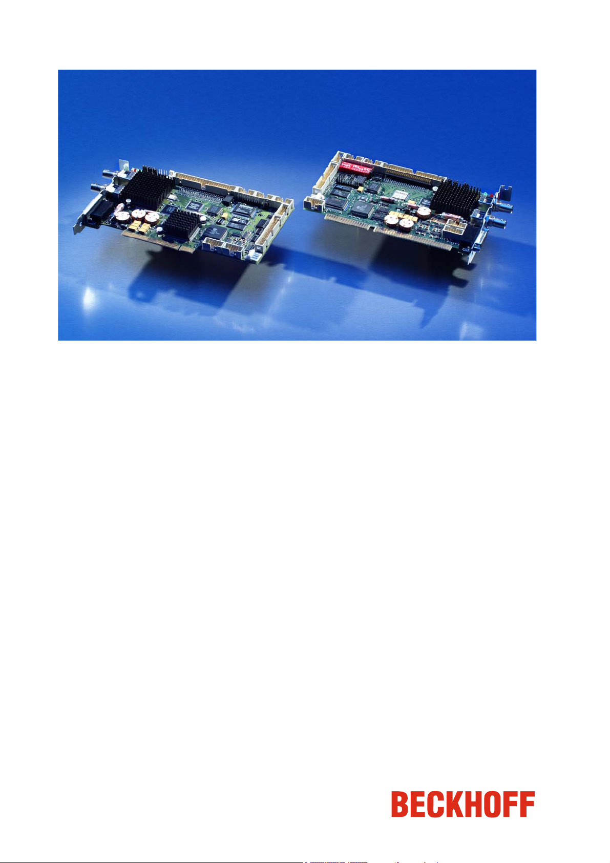
Beckhoff CP9030 / CP9035
CP-Link Cards
Version: 1.5
Date: 2009-10-05
Page 2

General instructions
Table of contents
1.
General instructions 5
Notes on the Documentation 5
Liability Conditions 5
2.
Beckhoff CP-Link System Description 6
CP-Link 6
Example: CP-Link "Single" Connection 7
Multi CP-Link 8
Example: CP-Link "Double" Connection 9
3.
Technical Data CP9030 10
Layout of the BECKHOFF CP-Link Card 10
Cable and jumper configurations 16
Advantech SBC 16
Bayview 50 / 52 Graphic Card 16
Boser HS6237 SBC 16
Inside Technology 686LCD SBC 17
MITAC 251 SBC 17
Vampower 7 Graphic Card 17
Vampower 8 Graphic Card 17
View of the CP9030 Slot Cover 18
CP9030 DPRAM Memory Allocation 19
CP9030 card pin assignments 22
Description of the Status LEDs 26
Jumper Assignments 27
ISA bus current consumption 27
4.
5.
6.
7.
8.
Technical Data CP9035 28
Layout of the BECKHOFF CP-Link Card 28
Cable and jumper configurations 30
CP9035 card pin assignments 30
Description of the Status LEDs 33
Jumper Assignments 34
Current consumption 34
View of the CP9035 Slot Cover 35
Technical Data CP9035 with DVI-Add Card 36
Layout of the CP9035 with DVI-Add Card 36
Multi CP-Link Cable-sets 37
CP-Link connecting cable 38
Appendix 40
Beckhoff Support & Service 40
Beckhoff branches and partner companies 40
Beckhoff Headquarters 40
Beckhoff Support 40
Beckhoff Service 40
CP9030 / CP9035 3
Page 3

General instructions
4 CP9030 / CP9035
Page 4

General instructions
General instructions
Notes on the Documentation
This description is only intended for the use of trained specialists in control
and automation engineering who are familiar with the applicable national
standards. It is essential that the following notes and explanations are
followed when installing and commissioning these components.
Liability Conditions
The responsible staff must ensure that the application or use of the
products described satisfy all the requirements for safety, including all the
relevant laws, regulations, guidelines and standards.
The documentation has been prepared with care. The products described
are, however, constantly under development. For that reason the
documentation is not in every case checked for consistency with
performance data, standards or other characteristics. None of the
statements of this manual represents a guarantee (Garantie) in the
meaning of § 443 BGB of the German Civil Code or a statement about the
contractually expected fitness for a particular purpose in the meaning of
§ 434 par. 1 sentence 1 BGB. In the event that it contains technical or
editorial errors, we retain the right to make alterations at any time and
without warning. No claims for the modification of products that have
already been supplied may be made on the basis of the data, diagrams
and descriptions in this documentation.
© This documentation is copyrighted. Any reproduction or third party use of
this publication, whether in whole or in part, without the written permission
of Beckhoff Automation GmbH, is forbidden.
CP9030 / CP9035 5
Page 5
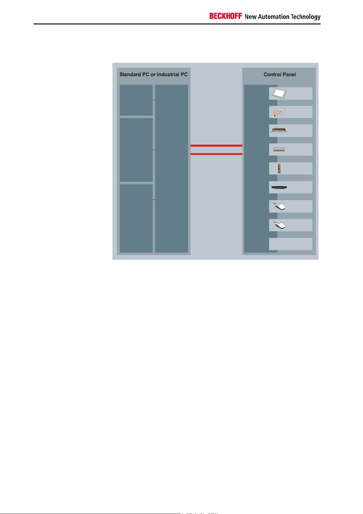
Beckhoff CP-Link System Description
Beckhoff CP-Link System Description
System
LCD graficcontroller
CP-Link
PC
multiplexer
CP-Link
Control Panel
multiplexer
TFT display
T
ouch screen
Motherboard
- Keyboard
- Serial interface
- Diskette drive
12 V DC from PC
power supply
CP-Link
giga bit serial link
2 coaxial cable
(max. 100 m)
Einschub
Einschub
Streifen
Streifen
Einschub
Einschub
Einschub
Streifen
Streifen
Streifen
START
K1
Schub
HELP
I
STOP
O
STOP
O
START
K1
Schub
HELP
I
O
STOP
PC keyboard
PLC keys
with LED
Pushbutton
Extension
Diskette
drive
RS232
interface
PS/2 mouse
interface
5V power supply
CP-Link
Flexibility
Maximum flexibility for location of the Control Panel on the equipment.
The connection from the Control Panel to the PC itself is made via CP Link,
a transmission technology having a data rate in the gigabit range. CP Link
implements transmission segments up to 100 m on a twin-core coaxial
cable. No additional power supply is needed. The CP-Link Interface is
implemented as an ISA and PCI bus plug-in card and is thus usable in any
PC. The PC is also equipped with a graphics card providing an LCD
interface. The PC ports for LC display, keyboard, COM ports, PS/2 mouse
and floppy drive are converted by the CP-Link plug-in card into a highfrequency serial signal and transmitted via coaxial cable to the Control
Panel. The CP-Link Interface in the Control Panel re-converts the serial
signal for the original PC ports, to which the components of the Control
Panel, such as keyboard, LC display, touch screen, touch pad, PS/2 mouse
and floppy drive are connected, but at a 100 meters longer distance than
would ordinarily be possible. There is a CP-Link channel for each direction
of the communication between the Control Panel and the PC. Two coaxial
cables are laid for this reason.
6 CP9030 / CP9035
Page 6
Beckhoff CP-Link System Description
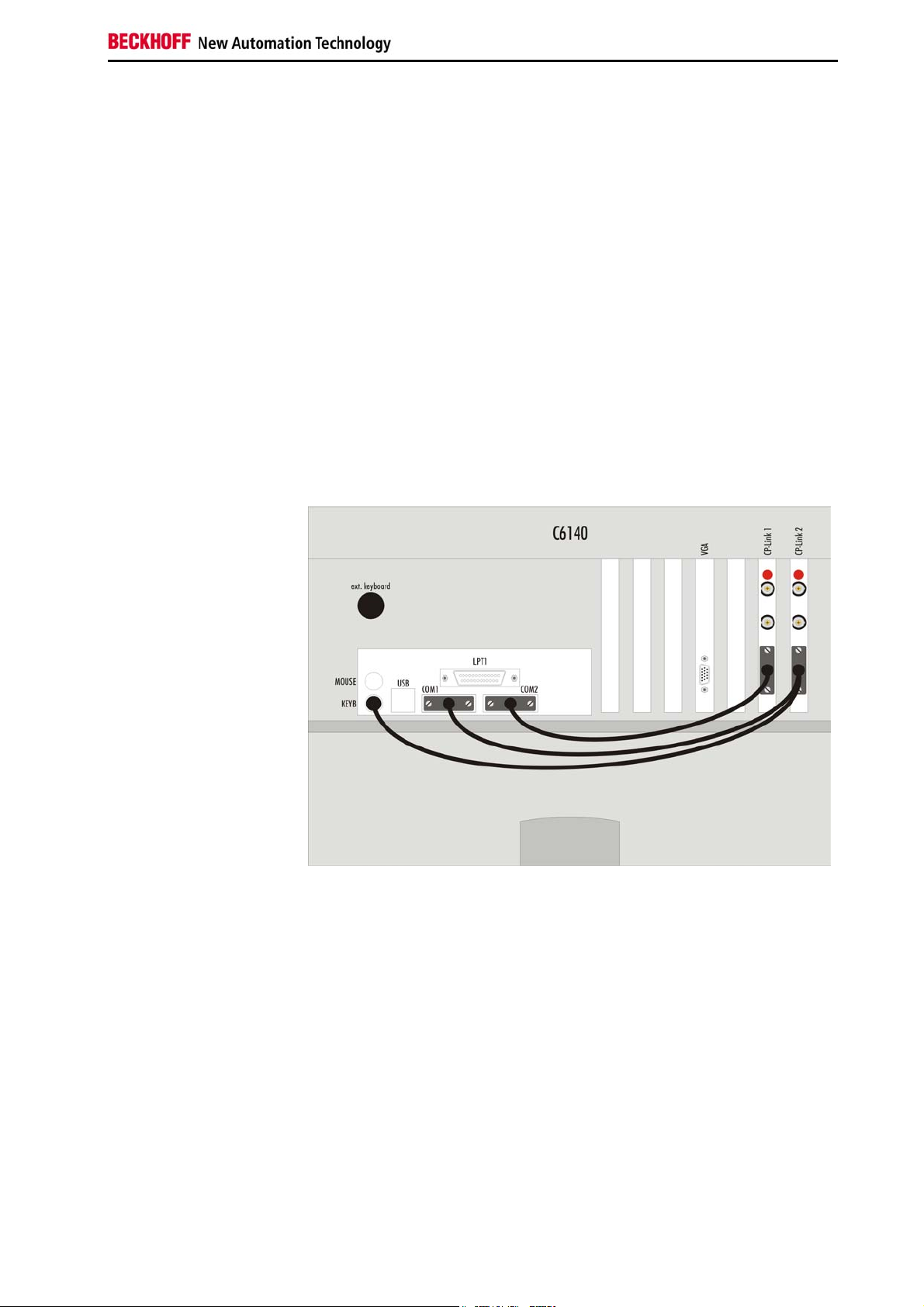
Example: CP-Link "Single" Connection
One Control Panel with Touchpad and Touchscreen
Fig. 3
The signals required for the touchpad (RS232) and touchscreen (RS232)
are distributed through connector ST303 to the computer's individual COM
ports. The sequence of the COM ports only has to be maintained for the
installation of the corresponding drivers. The keyboard signals are also
passed via ST303 to the motherboard's own keyboard connection.
Switching between the various keyboards (Control Panel membrane
keypad, a keyboard socket which may be present on the Control Panel, and
external keyboard connection on the PC) is performed on the CP-Link
board, which means that it is possible to operate all the keyboards in
parallel.
The BNC cables are connected to the CP-Link A and CP-Link B connectors
on the CP-Link card. Orientation is aided by a red mark on the card. The
cable types and the corresponding lengths are described below.
CP9030 / CP9035 7
Page 7
Beckhoff CP-Link System Description
grap
2
3
Multi CP-Link
Up to three Control Panels
Assembly and connections
in the PC
Up to three Control Panels can be connected to one PC. Each Control
Panel can be installed at a distance of up to 100 m from the PC, which
ensures maximum flexibility in locating the Control Panel on the equipment.
For each Control Panel, one CP-Link insert card is installed in the PC.
If a number of pointing devices or interfaces (touchpad, touchscreen,
RS232) are used with the Control Panel it is necessary for the PC to have a
corresponding number of interfaces.
CP- L I N K 0
CP- L I N K 0
CP- L I N K 01
ext. keyboard
hic card
to
All displays show the same image. This requires all the displays to have the
same format.
Data can be entered on the PC keyboard, on the keyboard of one of the
Control Panels or on a standard keypad connected to one of the Control
Panels or directly to the PC.
8 CP9030 / CP9035
Page 8
Beckhoff CP-Link System Description
Example: CP-Link "Double" Connection
One Control Panel with Touchscreen and one Control Panel with
Touchpad
Fig. 4
If we assume that the Control Panel with touchpad is connected to CP-Link
1 and that the Control Panel with touchscreen is connected to CP-Link 2,
then the signals from the one Control Panel for the touchpad (RS232) from
CP-Link 1 are passed to COM2, and the signals from the touchscreen
(RS232) of the other Control Panel are passed to COM 1. The keyboard
cable to the motherboard must be plugged into the card on the outside (CPLink 2). Further, a 1:1 connection from ST305 (CP-Link 1) to ST304 (CPLink 2) is required in order to pass the keyboard signals arising from CPLink 1 on to CP-Link 2.
The drivers must be installed in accordance with the assignments of the
touchpad and touchscreen.
The BNC cables are connected to the "CP-Link A" and "CP-Link B"
connectors on the CP-Link card. Orientation is aided by a red mark on the
card. The cable types and the corresponding lengths are described below.
CP9030 / CP9035 9
Page 9
Technical Data CP9030
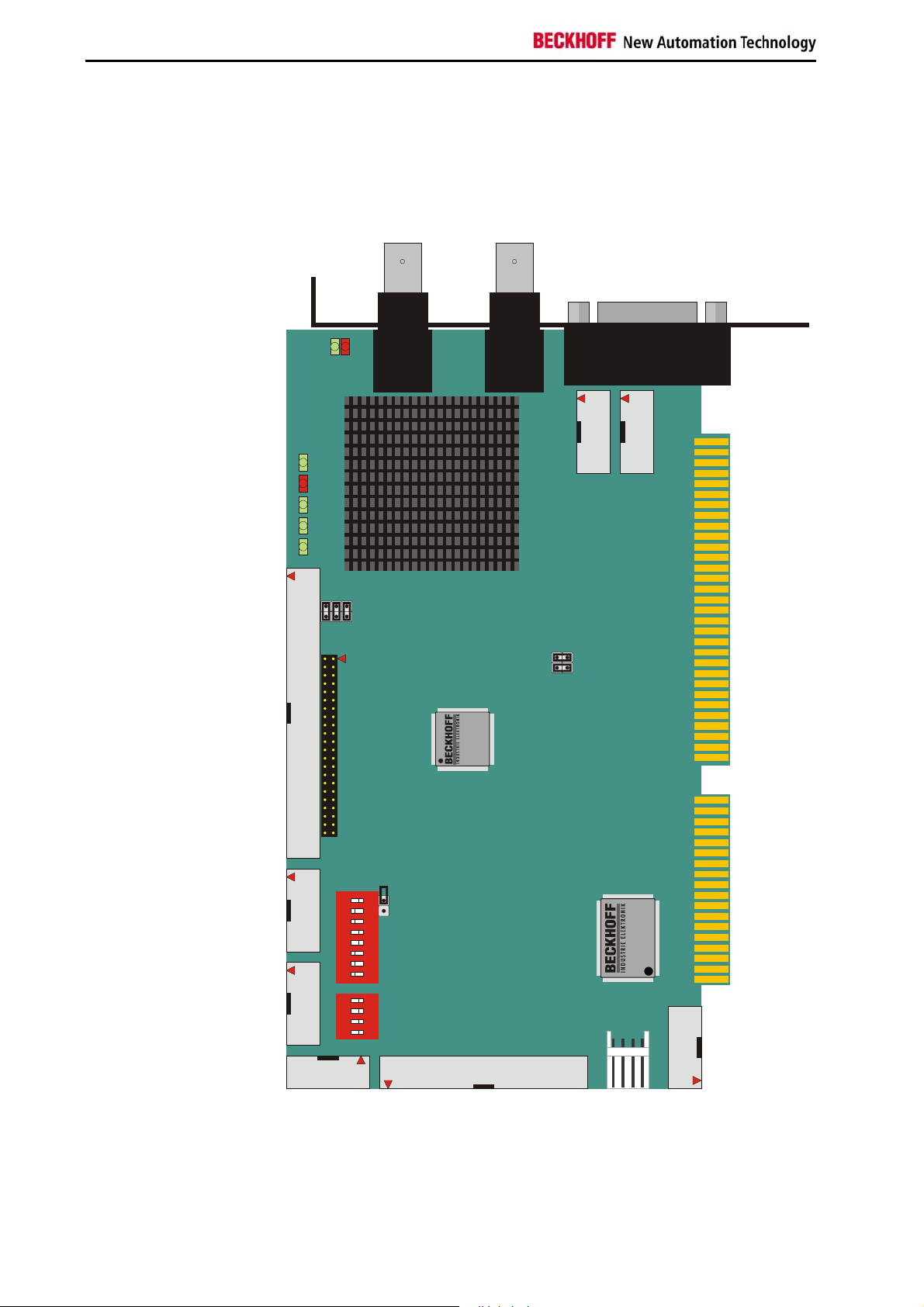
Technical Data CP9030
Layout of the BECKHOFF CP-Link Card
CP9030_3
Fig. 5
3
_
0
3
0
9
P
C
D
E
L
D
E
L
D
E
L
D
E
L
D
E
L
2
0
2
T
S
A
k
n
i
L
7
6
0
0
D
D
E
E
L
L
5
0
4
0
3
0
2
0
1
0
1
2
3
0
0
0
2
2
2
U
U
U
J
J
J
2
0
2
T
S
P
C
1
0
2
C
I
w
e
i
v
y
a
B
B
k
n
i
L
P
C
1
0
3
T
S
0
4
U
1
J
0
4
U
2
J
1
.
1
n
o
i
s
r
e
V
3
0
3
2
0
3
T
S
T
S
6
5
0
3
T
S
4
0
3
T
S
0
3
T
P
I
D
N
O
P
I
D
N
O
S
0
8
0
3
7
J
6
5
0
4
0
3
4
2
W
1
S
0
4
0
3
5
2
W
1
S
S
T
2
0
3
0
0
5
C
I
4
0
4
0
3
7
.
1
n
o
i
s
r
e
V
T
8
9
9
1
.
1
1
.
1
0
S
1
0
5
T
S
10 CP9030 / CP9035
Page 10

Technical Data CP9030
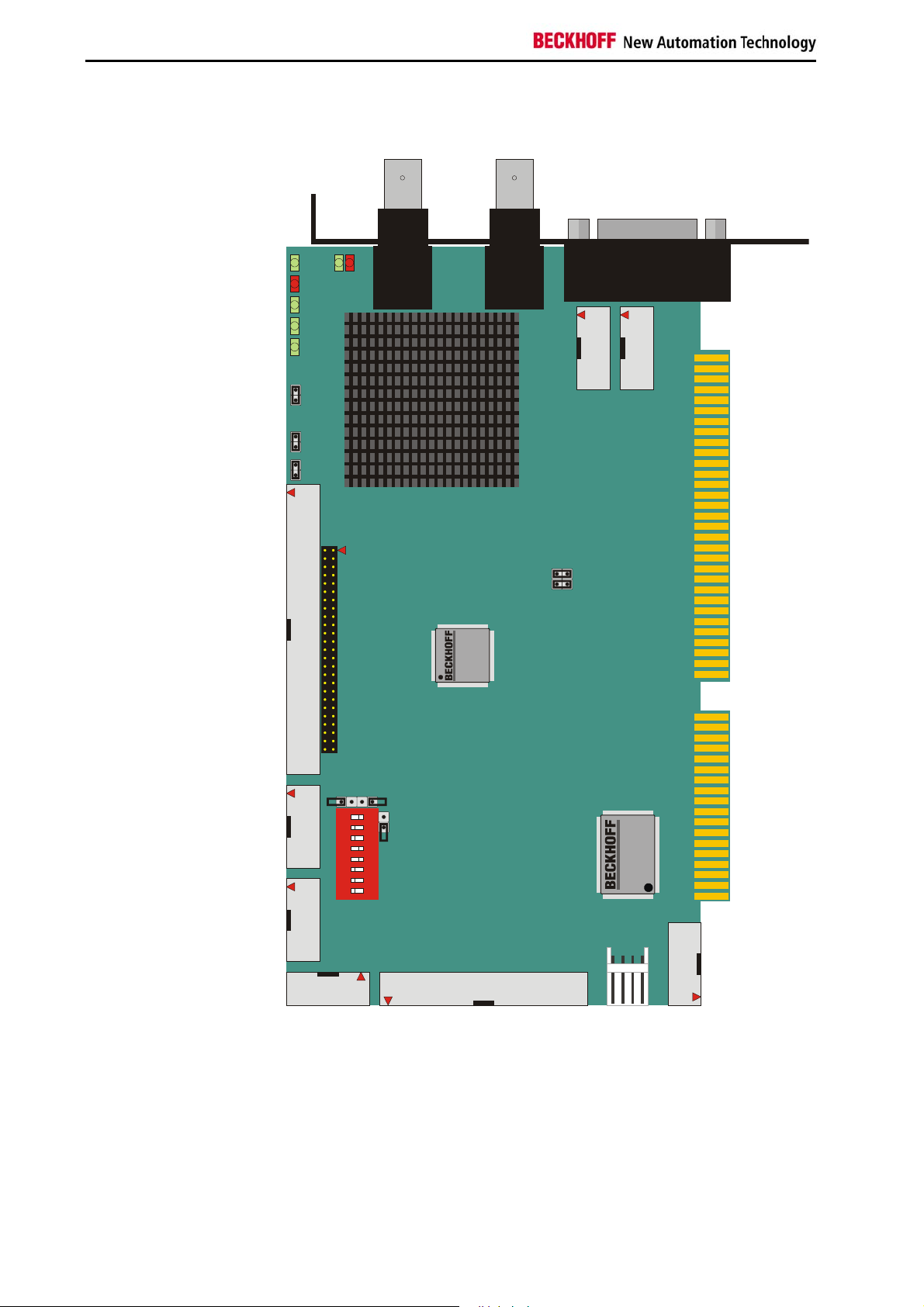
Configuration jumpers on the CP9030_3
Fig. 6
J26 9J268
J26 7J266
J26 5J264
J26 3J262
J26 1
J26 0
J249
J247
J245
J243
J241
J239
J237
J235
J233
J231
J229
J227
J225
J223
J221
J219
J217
J215
J213
J211
J209
J207
J205
J203
J201
J250
J248
J246
J244
J242
J240
J238
J236
J234
J232
J230
J228
J226
J224
J222
J220
J218
J216
J214
J212
J210
J208
J206
J204
J202
J258
J25 7
J256
J25 5
J254
J25 3
J252
J25 1
BECKHOFF CP9030_ 3
CP9030 / CP9035 11
Page 11
Technical Data CP9030
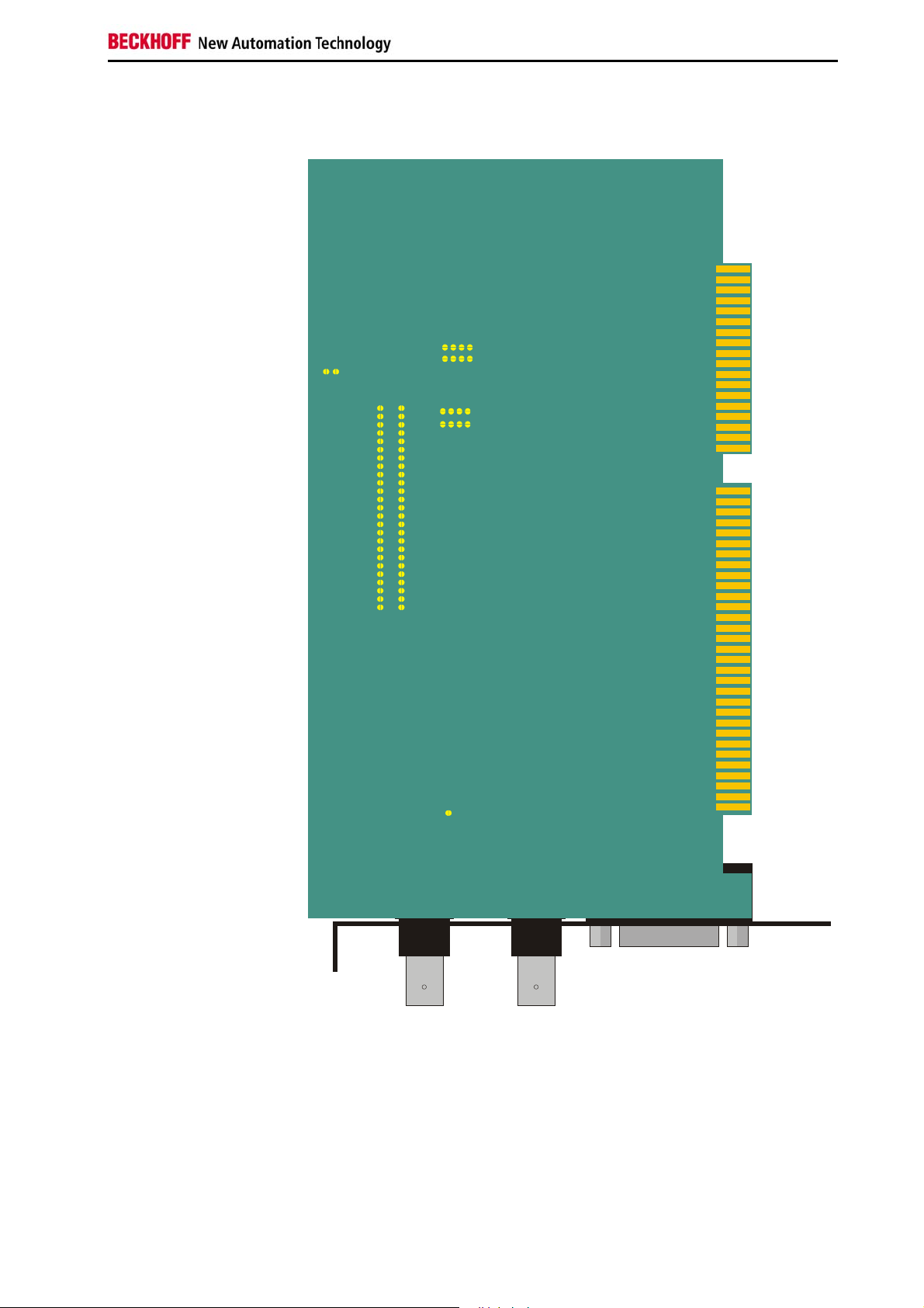
CP9030_4
Fig. 7
A
5
4
0
_
D
E
0
L
3
0
4
6
7
0
0
0
9
D
D
D
P
E
E
E
C
L
L
L
3
0
D
E
L
2
0
D
E
L
1
0
D
E
L
0
0
2
U
J
2
0
2
U
J
1
0
2
U
J
2
0
2
T
S
4
0
2
T
S
k
n
i
L
P
C
1
0
2
C
I
w
e
i
v
y
a
B
B
k
n
i
L
P
C
1
0
3
T
S
4
0
U
1
J
4
0
U
2
J
1
.
1
n
o
i
s
r
e
V
3
0
3
2
0
3
T
S
T
S
5
J
01J
5
0
2
6
5
0
3
T
S
4
0
3
T
S
0
3
T
P
I
D
N
O
S
8
0
0
3
J
7
6
5
0
4
0
3
4
2
W
1
S
S
T
6
0
0
0
0
5
C
I
4
0
4
0
3
7
.
1
n
o
i
s
r
e
V
T
S
1
0
5
T
S
12 CP9030 / CP9035
Page 12
Technical Data CP9030
Configuration jumpers on the CP9030_4
Fig. 8
J26 9J268
J26 7J266
J26 5J264
J26 3J262
J26 1
J26 0
J249
J247
J245
J243
J241
J239
J237
J235
J233
J231
J229
J227
J225
J223
J221
J219
J217
J215
J213
J211
J209
J207
J205
J203
J201
J250
J248
J246
J244
J242
J240
J238
J236
J234
J232
J230
J228
J226
J224
J222
J220
J218
J216
J214
J212
J210
J208
J206
J204
J202
J258
J25 7
J256
J25 5
J254
J25 3
J252
J25 1
LO100
BECKHOFF CP9030_ 4
CP9030 / CP9035 13
Page 13

Technical Data CP9030
ST40
, CP9030_5
Fig. 9
A
5
0
D
E
L
6
7
0
0
4
D
D
0
E
E
L
L
D
E
5
L
_
0
3
3
0
0
D
9
E
L
P
C
2
0
D
E
L
1
0
D
E
L
0
0
2
U
J
2
0
2
U
J
1
J
0
0
1
0
2
U
J
2
0
2
T
S
k
n
i
L
P
C
4
0
2
T
S
w
e
i
v
y
a
B
B
k
n
i
L
P
C
1
0
3
T
S
U
J
4
0
1
U
J
4
0
2
1
.
1
n
o
i
s
r
e
V
3
0
3
2
0
3
T
S
T
S
5
J
0
1J5
0
2
5
0
3
T
S
4
0
3
T
S
ST3 06
P
I
D
N
O
0
8
0
3
J
7
6
5
0
4
0
3
4
2
W
1
S
0
0
5
T
S
ST600
0
3
7
.
1
n
o
i
s
r
e
V
1
0
5
T
S
4
14 CP9030 / CP9035
Page 14

Technical Data CP9030
Configuration jumpers on the CP9030_5
Fig. 10
J269J268
J267J266
J265J264
J263J262
J261
J260
J249
J247
J245
J243
J241
J239
J237
J235
J233
J231
J229
J227
J225
J223
J221
J219
J217
J215
J213
J211
J209
J207
J205
J203
J201
J25 0
J24 8
J24 6
J24 4
J24 2
J24 0
J23 8
J23 6
J23 4
J23 2
J23 0
J22 8
J22 6
J22 4
J22 2
J22 0
J21 8
J21 6
J21 4
J21 2
J21 0
J20 8
J20 6
J20 4
J20 2
J25 2
J25 4
J25 6
J25 8
J251
J253
J255
J257
LO100
ST303
BECKHOFF CP9030_ 5
CP9030 / CP9035 15
Page 15

Technical Data CP9030
Cable and jumper configurations
Advantech SBC
CLOSED
J207, J208, J209, J210, J214, J239, J240, J245
LO100 (CP9030_4) for 15 inch display
OPEN
It is essential that the remaining jumpers are OPEN to avoid damaging the
CP-Link card or the graphic card / SBC!
Ribbon Cable ST205 (50 pin RM2.0)
Pin assignment 1:1
Pin 1-6 of the post connector remain open
Bayview 50 / 52 Graphic Card
CLOSED
J201, J202, J206, J209, J212, J214, J217, J220, J223, J226, J229, J232,
J235, J238, J241, J247
LO100 (CP9030_4) for 15 inch display
OPEN
It is essential that the remaining jumpers are OPEN to avoid damaging the
CP-Link card or the graphic card / SBC!
Ribbon Cable ST202 (50 pin RM2.54)
Pin assignment 1:1
Pins 1-4 of the ribbon cable must be disconnected
Boser HS6237 SBC
CLOSED
J201, J202, J203, J204, J208, J239
LO100 (CP9030_4) for 15 inch display
OPEN
It is essential that the remaining jumpers are OPEN to avoid damaging the
CP-Link card or the graphic card / SBC!
Ribbon Cable ST205 (50 pin RM2.0)
Pin assignment 1:1
Pin 1-6 of the post connector remain open
Pins 1, 2 and 35 of the ribbon cable must be disconnected
16 CP9030 / CP9035
Page 16

Technical Data CP9030
Inside Technology 686LCD SBC
CLOSED
J203, J209, J212, J214, J217, J220, J223, J226, J229, J232, J235, J238,
J240, J245, J250
LO100 (CP9030_4) for 15 inch display
OPEN
It is essential that the remaining jumpers are OPEN to avoid damaging the
CP-Link card or the graphic card / SBC!
Ribbon Cable ST202 (50 pin RM2.54)
Pin assignment 1:1
Pin 40 of the ribbon cable must be disconnected
MITAC 251 SBC
CLOSED
J203, J204, J215, J216, J221, J227, J228, J233, J234, J239, J240, J245,
J246
LO100 (CP9030_4) for 15 inch display
OPEN
It is essential that the remaining jumpers are OPEN to avoid damaging the
CP-Link card or the graphic card / SBC!
Ribbon Cable ST202 (50 pin RM2.54)
Pin assignment 1:1
Pins 3, 4 of the ribbon cable must be disconnected
Vampower 7 Graphic Card
CLOSED
J227, J229, J230, J230, J236, J238, J244, J246, J250
LO100 (CP9030_4) for 15 inch display
OPEN
It is essential that the remaining jumpers are OPEN to avoid damaging the
CP-Link card or the graphic card / SBC!
Ribbon Cable ST202 (50 pin RM2.54)
Pin assignment 1:1
Pins 29, 39, 43, 45 of the ribbon cable must be disconnected
Vampower 8 Graphic Card
CLOSED
J201, J202, J203, J204, J208, J239
LO100 (CP9030_4) for 15 inch display
OPEN
It is essential that the remaining jumpers are OPEN to avoid damaging the
CP-Link card or the graphic card / SBC!
Ribbon Cable ST205 (50 pin RM2.0)
Pin assignment 1:1
Pin 1-6 of the post connector remain open
CP9030 / CP9035 17
Page 17
Technical Data CP9030
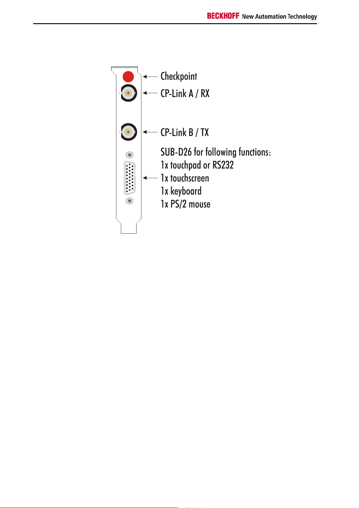
View of the CP9030 Slot Cover
Fig. 2
18 CP9030 / CP9035
Page 18
Technical Data CP9030
CP9030 DPRAM Memory Allocation
Address Denomination BIT 7 BIT 6 BIT 5 BIT 4 BIT 3 BIT 2 BIT 1 BIT 0
0x03FF
0x03FE
0x03FD
....
0x03F0
Request Active
Ready COM_F Toggle
Ident String
„CP9030 v1.730“
Toggle
0x03EF
0x03EE
0x03ED
0x03EC
0x03EB
0x03EA
0x03E9
0x030E
0x030F
0x030E
0x030D
0x030C
0x030B
0x030A
0x0309
0x0308
0x0307
0x0306
0x0305
0x0304
0x0303
0x0302
0x0301
0x0300
0x02FF
0x0280
0x027F
0x0200
0x01FF
0x0104
0x0103
0x0102
0x0101
0x0100
0x00FF
0x0004
0x0003
0x0002
0x0001
0x0000
Reserve
Control Keyb_on BLOFF
USV Status
Waiting Charged No
UPS control
CP-state Reset
CP-Control
Reserve
Pd error
Pd cycles
No. of pd input words
No. of pd output words
Process data input
...BUTTON 256
BUTTON 25..32 T 32
BUTTON 17.0.24
BUTTON 9.0.16
BUTTON 1.0.8
Process data output
...LED 256
LED 25..32 L 32 L 31 L 30 L 29 L 28 L 27 L 26 L 25
LED 17..24 L 24 L 23 L 22 L 21 L 20 L 19 L 18 L 17
LED 9..16 L 16 L 15 L 14 L 13 L 12 L 11 L 10 L 9
LED 1..8 L 8 L 7 L 6 L 5 L 4 L 3 L 2 L 1
Ackn
Reset
Request
T 24 T 23 T 22 T 21 T 20 T 19 T 18 T17
T 16 T 15 T 14 T 13 T 12 T 11 T 10 T9
T 8 T 7 T 6 T 5 T4 T 3 T 2 T 1
Charge controller
battery
T 31 T 30 T 29 T 28 T 27 T 26 T 25
Charging
PDLenErr
CnfErr
Battery
voltage
Ext. vers
. OK
Active
KbusErr
CP9030 / CP9035 19
Page 19

Technical Data CP9030
LED1..256
Output for LEDs; "1" = LED on
Up to 256 LEDs can be controlled
BUTTON1..256
Inputs for buttons; "1" = button pressed
Up to 256 buttons can be read
No. of pd outp. words (number of process data output words)
A reference value with which the output status derived from the Control
Panel (CP2020 pd outp.words) is compared. If they differ, then for reasons
of safety no outputs are set.
No. of pd inp. words (number of process data input words)
A reference value with which the input status derived from the Control Panel
(CP2020 pd inp.words) is compared. If they differ, then for reasons of
safety no outputs are set. Inputs can continue to be read.
Pd cycles (process data cycles)
A continuously incremented 8-bit counter. If it is active, Pd errors remains
unchanged.
Pd errors (process data errors)
An error counter that is incremented whenever errors occur in transmission
protocols.
CP2020 Pd outp. words (process data output words)
Returns the size (in words) of the process data output status determined by
the Control Panel.
CP2020 Pd inp. words (process data input words)
Returns the size (in words) of the process data input status determined by
the Control Panel.
CP-Control
Reset request : "1" reset of the CP-Link electronics
CP-state
Reset ackn. : "1" - reset carried out
PDLenErr : "1" process data length error
CnfErr : "1"
KbusErr : "1" - communication error; e.g. to the button extensions
C9900-E6xx
UPS control
Active : "1" battery operation is supported
UPS Status
Ext. vers. OK : "1" input voltage (24V DC) is present
Battery voltage : "1" - the battery voltage is sufficient
Charging : "1" - The battery pack is being charged
No battery : "1" - The battery pack is not present or is defective
Charged : "1" - The battery pack is fully charged
Waiting : "1" - Pause during the process of charging the battery pack
20 CP9030 / CP9035
Page 20

Technical Data CP9030
Control
BLOFF : "1" switches the background illumination off
Keyb_on : "1" disables the Control Panel's membrane keypad
J300 (CP9030_3) J501 and J502 must be set
Ident String
Returns the current firmware status of the CP-Link card
Ready
COM_F : "1" - A communication error has occurred
Request
If the CP-Link card is being operated in synchronous mode (as, for
example, with TwinCAT), then the data should not be fetched from the PLC
until both the values (Active and Toggle) are "1". Only then is a correct
value for the buttons guaranteed.
CP9030 / CP9035 21
Page 21

Technical Data CP9030
CP9030 card pin assignments
ST202 / ST204 (Display connection)
The assignment varies according to the programming.
12
49 50
PIN Signal PIN Signal PIN Signal
IC201
indicates the programmed graphic card adaptation and its version.
IC500
indicates the revision of the BECKHOFF firmware for the CP-Link card.
12
ST305 (Keyboard switching for the next CP-Link card)
PIN Signal PIN Signal
nc
nc
nc
DISPON
nc
GND
ENAB
G2
G3
GND
G4
G5
GND
GND
B6
B7
GND
R0
R1
910
12
910
ST304 (External keyboard connection)
PIN Signal PIN Signal
12
910
ST306 (PS/2 mouse connection)
PIN Signal PIN Signal
22 CP9030 / CP9035
Page 22

Technical Data CP9030
12
ST203, ST600 (FDD connection for the Control Panel)
PIN Signal PIN Signal PIN Signal
33 34
12
910
12
910
12
ST501 (24V UPS control)
PIN Signal PIN Signal
ST302 (Touchscreen connection)*
PIN Signal PIN Signal
ST301 (Touchpad/RS232 connection)
PIN Signal PIN Signal
910
CP9030 / CP9035 23
ST404 (Additional voltage connection for the CP-Link card)
PIN Signal
Page 23

Technical Data CP9030
ST303 external connection
ST303
PIN
RS232
D-SUB 9
female*
Touchscreen
D-SUB 9
female
Keyboard
DIN 5
Keyboard
PS/2
Mouse
PS/2
* The RS232 and Touchpad connections are identical
24 CP9030 / CP9035
Page 24

Technical Data CP9030
SW500 (Index setting)
ON DIP
1
234
PIN Signal
ON D IP
12345678
"1"=ON - "0"=OFF
SW400 (Address setting)
Segment
C800
C880
C900
C980
CA00
CA80
CB00
CB80
CC00
CC80
CD00
CD80
CE00
CE80
CF00
CF80
D000
D080
D100
D180
D200
D280
D300
D380
D400
D480
D500
D580
D600
D680
D700
D780
D800
D880
D900
D980
DA00
DA80
DB00
DB80
DC00
8 7 6 5 4 3 2 1
0 1 1 0 1 1 1 1
0 1 1 0 1 1 1 0
0 1 1 0 1 1 0 1
0 1 1 0 1 1 0 0
0 1 1 0 1 0 1 1
0 1 1 0 1 0 1 0
0 1 1 0 1 0 0 1
0 1 1 0 1 0 0 0
0 1 1 0 0 1 1 1
0 1 1 0 0 1 1 0
0 1 1 0 0 1 0 1
0 1 1 0 0 1 0 0
0 1 1 0 0 0 1 1
0 1 1 0 0 0 1 0
0 1 1 0 0 0 0 1
0 1 1 0 0 0 0 0
0 1 0 1 1 1 1 1
0 1 0 1 1 1 1 0
0 1 0 1 1 1 0 1
0 1 0 1 1 1 0 0
0 1 0 1 1 0 1 1
0 1 0 1 1 0 1 0
0 1 0 1 1 0 0 1
0 1 0 1 1 0 0 0
0 1 0 1 0 1 1 1
0 1 0 1 0 1 1 0
0 1 0 1 0 1 0 1
0 1 0 1 0 1 0 0
0 1 0 1 0 0 1 1
0 1 0 1 0 0 1 0
0 1 0 1 0 0 0 1
0 1 0 1 0 0 0 0
0 1 0 0 1 1 1 1
0 1 0 0 1 1 1 0
0 1 0 0 1 1 0 1
0 1 0 0 1 1 0 0
0 1 0 0 1 0 1 1
0 1 0 0 1 0 1 0
0 1 0 0 1 0 0 1
0 1 0 0 1 0 0 0
0 1 0 0 0 1 1 1
CP9030 / CP9035 25
Page 25

Technical Data CP9030
Segment
DC80
DD00
DD80
DE00
DE80
DF00
DF80
E000
E080
E100
E180
E200
E280
E300
E380
E400
E480
E500
E580
E600
E680
E700
E780
Description of the Status LEDs
8 7 6 5 4 3 2 1
0 1 0 0 0 1 1 0
0 1 0 0 0 1 0 1
0 1 0 0 0 1 0 0
0 1 0 0 0 0 1 1
0 1 0 0 0 0 1 0
0 1 0 0 0 0 0 1
0 1 0 0 0 0 0 0
0 0 1 1 1 1 1 1
0 0 1 1 1 1 1 0
0 0 1 1 1 1 0 1
0 0 1 1 1 1 0 0
0 0 1 1 1 0 1 1
0 0 1 1 1 0 1 0
0 0 1 1 1 0 0 1
0 0 1 1 1 0 0 0
0 0 1 1 0 1 1 1
0 0 1 1 0 1 1 0
0 0 1 1 0 1 0 1
0 0 1 1 0 1 0 0
0 0 1 1 0 0 1 1
0 0 1 1 0 0 1 0
0 0 1 1 0 0 0 1
0 0 1 1 0 0 0 0
LED 01 - 12V supply voltage present
If the LED is illuminated, the 12V supply voltage for the Control Panel is
present at the lower BNC socket (CP-Link B). If it is not lit there may be a
short circuit, or the PC power supply unit may not be operating correctly.
LED 02 - Transmit PLL locked
If the LED is lit, the clock signal from the video card is present. If it is not lit,
then either the video card is not operating correctly, or the connection of the
video card to the CP9030 is not made properly.
LED 03 - Receive PLL locked
If the LED is lit, data are being sent from the Control Panel to the PC. If it is
not lit, the most probable reason is that the upper coaxial cable (CP-Link A)
is defective or is not properly connected.
LED 04 - Receive data error
If the LED lights up, receive errors are occurring.
This LED is lit continuously if there is no connection to the Control Panel.
26 CP9030 / CP9035
Page 26

Technical Data CP9030
LED 05 - Not used
LED 06 - CP-Link RUN
This LED flashes for a short period when the computer is switched on, and
then becomes continuously lit. When the LED is lit, the communication
software on the CP-Link has started running.
LED 07 - CP-Link COMM-ERR
If the LED flashes, data errors are occurring. A single flash when the screen
mode is changed is normal. Transmission is then resynchronised. If the
LED continues flashing, then either the coaxial cable is damaged, or there is
excessive interference from other devices such as frequency converters,
large transformers, etc.. This may be remedied through the use of highquality double-screened coaxial cable.
Jumper Assignments
JU200
10 inch display in the Control Panel (OPEN)
JU203 (CP9030_3)
JU201
Floppy in the Control Panel (OPEN)
JU202
Floppy in the Control Panel (OPEN)
JU401
12V (always set)
JU402
12V (always set)
J300
If the jumper is set then it is possible for the Control Panel's keyboard to be
disabled under TwinCat.
J501
If this jumper and jumper J300 are set then it is possible for the Control
Panel's keyboard and touchscreen to be disabled under TwinCat.
The standard setting is for JU200 (JU203), JU201, JU202, JU401 and
JU402 to be set. Do not change any of the factory settings without first
contacting our Technical Support.
ISA bus current consumption
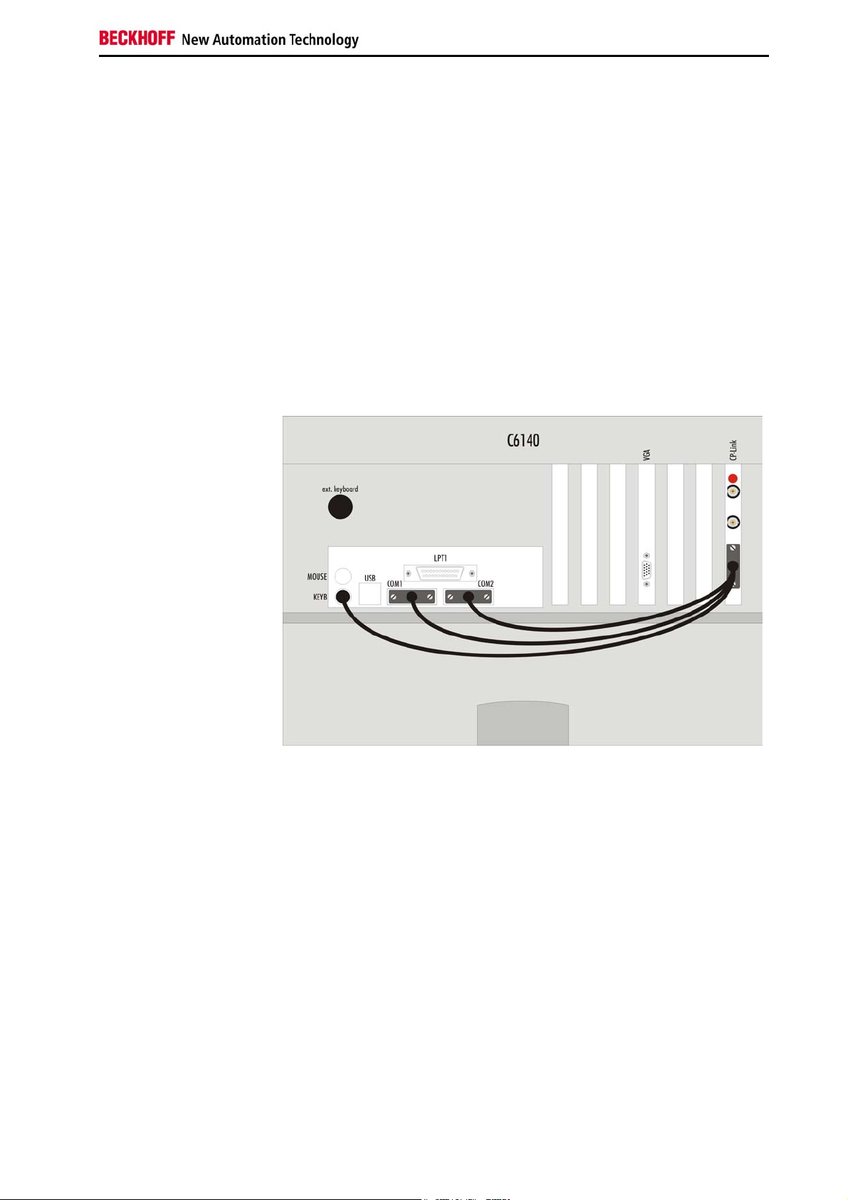
The CP9030 card is powered primarily from the PC's ISA bus. At larger
distances (> 50 m) it is recommended that the additional power supply
connection, ST404, is used.
ISA bus current consumption 5V: approx. 1.0 A
ISA bus current consumption 12V: approx. 1.5 A
CP9030 / CP9035 27
Page 27
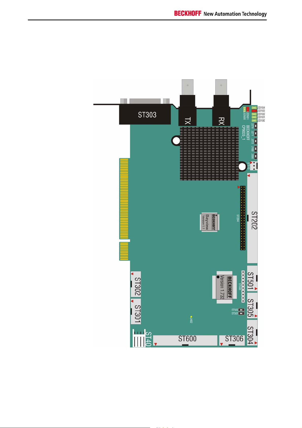
Technical Data CP9035
Technical Data CP9035
Layout of the BECKHOFF CP-Link Card
CP9035_1
Fig. 11
28 CP9030 / CP9035
Page 28

Technical Data CP9035
Configuration jumpers on the CP9035_1
Fig. 12
J269J26 8
J267J26 6
J265J26 4
J263J26 2
J260
J261
J250
J249
J247
J245
J243
J241
J239
J237
J235
J233
J231
J229
J227
J225
J223
J221
J219
J217
J215
J213
J211
J209
J207
J205
J203
J201
J248
J246
J244
J242
J240
J238
J236
J234
J232
J230
J228
J226
J224
J222
J220
J218
J216
J214
J212
J210
J208
J206
J204
J202
J258
J257
J256
J255
J254
J253
J252
J251
LO100
RX
TX
ST3 03
BECKHOFF CP9035_ 1
CP9030 / CP9035 29
Page 29
Technical Data CP9035
Cable and jumper configurations
The jumper and cable configurations are compatible with the CP9030
ISA version.
CP9035 card pin assignments
12
49 50
IC201
12
ST202 [RM2.54] / ST204 [RM2.0] – display connection
The assignment varies according to the programming.
PIN Signal PIN Signal PIN Signal
indicates the programmed graphic card adaptation and its version.
IC500
indicates the revision of the BECKHOFF firmware for the CP-Link card.
ST305 (Keyboard switching for the next CP-Link card)
PIN Signal PIN Signal
910
12
910
30 CP9030 / CP9035
ST304 (External keyboard connection)
PIN Signal PIN Signal
Page 30
Technical Data CP9035
12
ST306 (PS/2 mouse connection)
PIN Signal PIN Signal
910
12
33 34
12
ST600 (FDD connection for the Control Panel)
PIN Signal PIN Signal PIN Signal
ST501 (24V UPS control)
PIN Signal PIN Signal
910
12
910
12
910
ST302 (Touchscreen connection)*
PIN Signal PIN Signal
ST301 (Touchpad/RS232 connection)
PIN Signal PIN Signal
CP9030 / CP9035 31
Page 31
Technical Data CP9035
ST401 (Voltage connection for the CP-Link card)
PIN Signal
ST303 external connection
ST303
PIN
RS232
D-SUB 9
female*
Touchscreen
D-SUB 9
female
Keyboard
DIN 5
Keyboard
PS/2
Mouse
PS/2
* The RS232 and Touchpad connections are identical
32 CP9030 / CP9035
Page 32
Technical Data CP9035
Description of the Status LEDs
LED 100 - 12V supply voltage present
If the LED is lit, the clock signal from the video card is present. If it is not lit,
If the LED is lit, data are being sent from the Control Panel to the PC. If it is
If the LED lights up, receive errors are occurring.
This LED flashes for a short period when the computer is switched on, and
If the LED flashes, data errors are occurring. A single flash when the screen
If the LED is illuminated, the 12V supply voltage for the Control Panel is
present at the lower BNC socket (CP-Link B). If it is not lit there may be a
short circuit, or the PC power supply unit may not be operating correctly.
LED 101 - Transmit PLL locked
then either the video card is not operating correctly, or the connection of the
video card to the CP9030 is not made properly.
LED 102 - Receive PLL locked
not lit, the most probable reason is that the upper coaxial cable (CP-Link A)
is defective or is not properly connected.
LED 103 - Receive data error
This LED is lit continuously if there is no connection to the Control Panel.
LED 104 - Not used
LED 500 - CP-Link RUN
then becomes continuously lit. When the LED is lit, the communication
software on the CP-Link has started running.
LED 501 - CP-Link COMM-ERR
mode is changed is normal. Transmission is then resynchronised. If the
LED continues flashing, then either the coaxial cable is damaged, or there is
excessive interference from other devices such as frequency converters,
large transformers, etc.. This may be remedied through the use of highquality double-screened coaxial cable.
CP9030 / CP9035 33
Page 33

Technical Data CP9035
Jumper Assignments
J300
If this jumper is set then it is possible for the Control Panel's keyboard to be
disabled by software.
J100
Is set if a PS/2 mouse is connected. The Control Panel must be designed
for this
J272
Must be withdrawn for a 10" Control Panel
J271
Must be withdrawn if the Control Panel is fitted with a floppy drive.
J270
Must be withdrawn if the Control Panel is fitted with a floppy drive.
J501
If jumper J501 and jumper J300 are set then it is possible software to
disable the Control Panel's keyboard and its touchscreen.
J270, J271 and J272 are normally set. Do not change any of the factory
settings without first contacting our Technical Support.
Current consumption
The CP9035 card is powered exclusively through the ST401 power supply
connector. It cannot be powered via the PCI bus - this could damage the
motherboard.
Current consumption 5V: approx. 1.0 A
Current consumption 12V: approx. 1.5 A
34 CP9030 / CP9035
Page 34

Technical Data CP9035
View of the CP9035 Slot Cover
Fig. 13
CP9030 / CP9035 35
Page 35

Technical Data CP9035 with DVI-Add Card
Technical Data CP9035 with DVI-Add Card
Layout of the CP9035 with DVI-Add Card
Fig. 14
LED100
ST101
ST401
Note
36 CP9030 / CP9035
The technical data of the CP9035 CP-Link card with DVI-Add card
correspond with the data of the CP9035 without DVI-Add card.
For operating the CP-Link card, the power supply has to be connected to
ST101 and ST401.
Connect power supply
Take care that the connectors ST101 and ST401 are connected to the
power supply.
ST101 and ST401 are connected via a Y-cable, which is included in
delivery. The LED 100 indicates the correct power supply.
Page 36

Multi CP-Link Cable-sets
Multi CP-Link Cable-sets
One multi CP-Link cable set is needed to connect multiple Control Panel to a PC.
Multi CP-
Link
C9900-K240 cable set for multi CP-Link for installation of 2 CP-Link interface
C9900-K244 cable set for multi CP-Link for installation of 2 CP-Link interface
C9900-K245 cable set for multi CP-Link for installation of 2 CP-Link interface
C9900-K250 cable set for multi CP-Link for installation of 3 CP-Link interface
C9900-K254 cable set for multi CP-Link for installation of 3 CP-Link interface
C9900-K255 cable set for multi CP-Link for installation of 3 CP-Link interface
Cable sets for installation of multiple CP-Link-Interface cards
CP9030 into one PC
cards CP903x into C6140, C6150, C6240, C6250 or other PCs
with PCI graphic adapter with LCD interface type Bayview 50
C9900-A600, C9900-A602, C9900-A604, C9900-A610, C9900A612, C9900-A614
cards CP903x into C5101, C6110, C6120, C6130, C6220 or other
PCs with slot motherboard with LCD interface type Boser HS6237
cards CP9035 into C3xxx, C5102, C6140, C6150, C6240, C6250
or other PCs with ATX motherboard for Intel® Celeron® and
Pentium® 4 with on-board graphic and ADD card
CP9030 / CP9035 37
Page 37

CP-Link connecting cable
CP-Link connecting cable
One cable set is needed to connect a Control Panel to a PC. Request for
other dimensions.
Coaxial
cable-sets
C9900-K114
C9900-K115
C9900-K116
C9900-K117
C9900-K118
C9900-K119
C9900-K120
C9900-K121
C9900-K122
C9900-K123
C9900-K124
C9900-K125
C9900-K126
CP-Link connecting cable
CP-Link cable set with BNC connectors
– length 3 m (cable type Belden H155, bending radius 35 mm),
2 cables included
CP-Link cable set with BNC connectors
– length 5 m (cable type Belden H155, bending radius 35 mm),
2 cables included
CP-Link cable set with BNC connectors
– length 10 m (cable type Belden H155, bending radius 35 mm),
2 cables included
CP-Link cable set with BNC connectors
– length 15 m (cable type Belden H155, bending radius 35 mm),
2 cables included
CP-Link cable set with BNC connectors
– length 20 m (cable type H155, bending radius 35 mm), 2 cables
included
CP-Link cable set with BNC connectors
– length 30 m (cable type H2000FLEX, bending radius 50 mm),
2 cables included
CP-Link cable set with BNC connectors
– length 35 m (for ease of installation: 0.5 m Belden H155 + 35 m
H2000FLEX, bending radius 50 mm),
2 cables included
CP-Link cable set with BNC connectors
– length 50 m (for ease of installation: 0.5 m Belden H155 + 50 m
H2000FLEX, bending radius 50 mm),
2 cables included
CP-Link cable set with BNC connectors
– length 65 m (for ease of installation: 0.5 m Belden H155 + 65 m
H2000FLEX, bending radius 50 mm),
2 cables included
CP-Link cable set with BNC connectors
– length 70 m (for easy installation at the PC and the mounting
arm: 1 m Aircell7 + 61 m Cellflex + 8 m Aircell7),
2 cables included
CP-Link cable set with BNC connectors
– length 80 m (for easy installation at the PC and the mounting
arm: 1 m Aircell7 + 71 m Cellflex + 8 m Aircell7),
2 cables included
CP-Link cable set with BNC connectors
– length 90 m (for easy installation at the PC and the mounting
arm: 1 m Aircell7 + 81 m Cellflex + 8 m Aircell7),
2 cables included
CP-Link cable set with BNC connectors
– length 100 m (for easy installation at the PC and the mounting
arm: 1 m Aircell7 + 91 m Cellflex + 8 m Aircell7),
2 cables included
38 CP9030 / CP9035
Page 38

CP-Link connecting cable
Coaxial
cable-sets
C9900-K140
C9900-K141
C9900-K142
C9900-K143
C9900-K144
CP-Link cable sets, suitable as trailing cable
CP-Link cable set with BNC connectors, suitable as trailing cable
– length 3 m (cable type RG214 HIFLEX, bending radius 35 mm),
2 cables included
CP-Link cable set with BNC connectors, suitable as trailing cable
– length 5 m (cable type RG214 HIFLEX, bending radius 35 mm),
2 cables included
CP-Link cable set with BNC connectors, suitable as trailing cable
– length 10 m (cable type RG214 HIFLEX, bending radius
35 mm), 2 cables included
CP-Link cable set with BNC connectors, suitable as trailing cable
– length 15 m (cable type RG214 HIFLEX, bending radius
35 mm), 2 cables included
CP-Link cable set with BNC connectors, suitable as trailing cable
– length 20 m (cable type RG214 HIFLEX, bending radius
35 mm), 2 cables included
CP9030 / CP9035 39
Page 39

Appendix
Appendix
Beckhoff Support & Service
Quote the project number
Beckhoff and their partners around the world offer comprehensive support
and service, guaranteeing fast and competent assistance with all questions
related to Beckhoff products and system solutions.
Beckhoff branches and partner companies
Please contact your Beckhoff branch office or partner company for local
support and service on Beckhoff products!
The contact addresses for your country can be found in the list of Beckhoff
branches and partner companies: www.beckhoff.com
You will also find further documentation for Beckhoff components there.
Beckhoff Headquarters
Beckhoff Automation GmbH
Eiserstraße 5
33415 Verl
Germany
Phone: +49(0)5246/963-0
Fax: +49(0)5246/963-198
e-mail: info@beckhoff.com
Beckhoff Support
Beckhoff offers you comprehensive technical assistance, helping you not
only with the application of individual Beckhoff products, but also with wideranging services:
• worldwide support
• design, programming and commissioning of complex automation
systems
• training program for Beckhoff system components
Hotline:
Fax: +49(0)5246/963-9157
e-mail: support@beckhoff.com
+49(0)5246/963-157
Beckhoff Service
The Beckhoff service center supports you in all matters of after-sales
service:
• on-site service
• repair service
• spare parts service
• hotline service
Hotline:
Fax: +49(0)5246/963-479
e-mail: service@beckhoff.com
If servicing is required, please quote the project number of your product.
+49(0)5246/963-460
40 CP9030 / CP9035
 Loading...