

Page 1
Installation and Operating instructions for
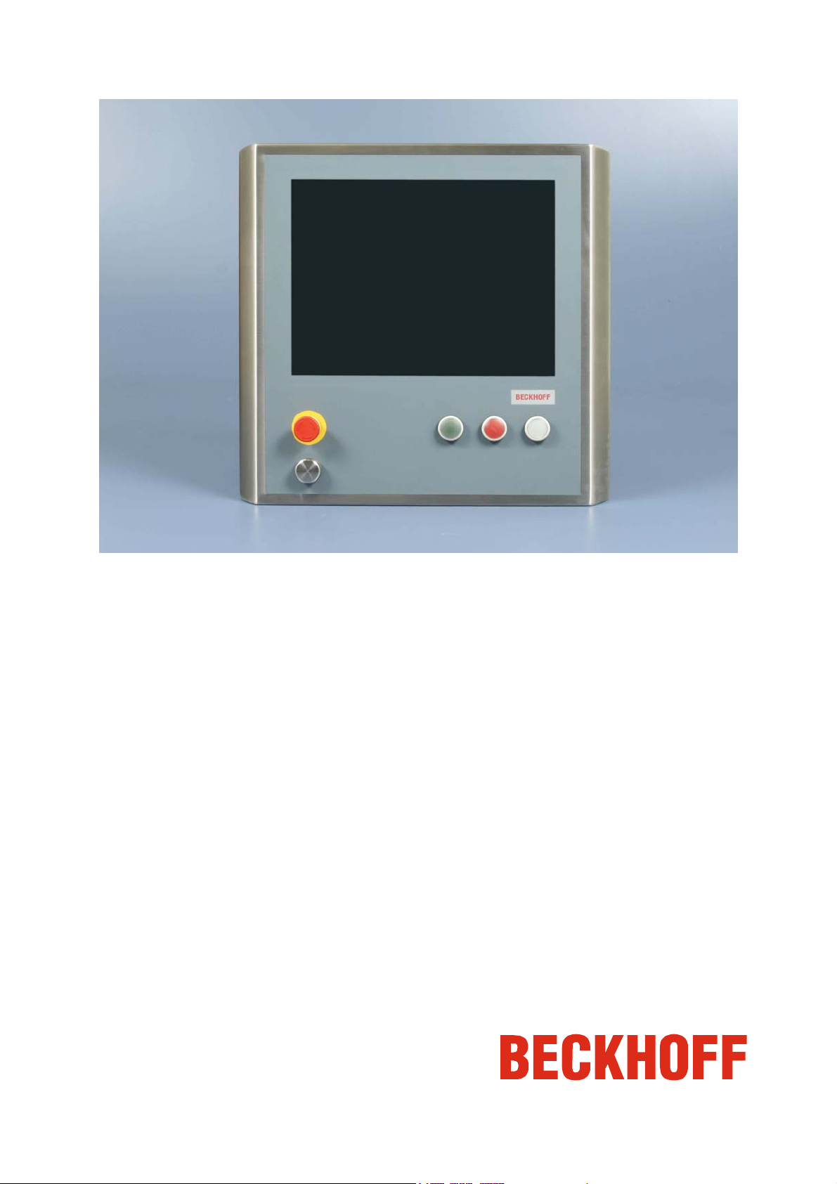
CP790x-140x
IP65 Stainless Control Panel
Version: 1.1
Date: 2013-01-17
Page 2

Page 3

Table of contents
Table of contents
1 Foreword 3
1.1 Notes on the Documentation 3
1.1.1 Liability Conditions 3
1.1.2 Trademarks 3
1.1.3 Patent Pending 3
1.1.4 Copyright 3
1.1.5 State at Delivery 3
1.1.6 Delivery conditions 3
1.2 Description of safety symbols 4
1.3 Basic safety measures 5
1.4 Operator’s obligation to exercise diligence 6
1.4.1 National regulations 6
1.4.2 Procedure in the event of a fault 6
1.4.3 Operator requirements 6
2 Product Description 7
2.1 Product overview 7
2.2 Appropriate Use 9
2.3 Opening the connection area 9
2.4 Connections 10
2.4.1 DVI-E Input (Digital Visual Interface-Extended) (X101) 11
2.4.2 Power Supply (X102) 12
2.4.3 USB-E Input (USB-Extended) (X103) 12
2.4.4 Protective Earthing 12
2.4.5 Connection Emergency stop and push-buttons CP790x-1401 (XS01) 13
2.4.6 USB-Port at the Front (CP790x-1401) 14
2.5 Connection Kits/ Connection Cables 14
2.5.1 Connection Cables Emergency Stop and Push-Buttons, optional 14
2.5.2 Connection Kits for DVI-E/ USB-E connection, optional 15
3 Installation 16
3.1 Transport and Unpacking 16
3.1.1 Transport 16
3.1.2 Unpacking 16
4 Mounting 17
4.1 Mounting arm installation 17
4.1.1 Welding the mounting arm tube 17
4.1.2 Mounting the O-rings 18
CP790x-140x 1
Page 4

Table of contents
4.1.3 Mounting the mounting arm 19
4.2 Connecting the Control Panel 20
4.2.1 Connecting cables 20
4.2.2 Protective Earthing 20
5 Operating Instructions 21
5.1 Switching the Control Panel on and off 21
5.1.1 Switching on 21
5.1.2 Shutting down and switching off 21
5.2 Operation 21
5.2.1 Setting the transmission rate 21
5.2.2 Emergency stop button and electromechanical push-buttons in the front 22
5.3 Servicing and maintenance 22
5.3.1 Cleaning 22
5.3.2 Maintenance 22
5.4 Emergency procedures 22
5.5 Shutting down 22
5.5.1 Disposal 22
6 Troubleshooting 23
7 Assembly dimensions 24
8 Wiring Diagram Emergency stop button and push-buttons 33
9 Technical Data 34
10 Appendix 35
10.1 Beckhoff Support and Service 35
10.1.1 Beckhoff branches and partner companies 35
10.1.2 Beckhoff company headquarters 35
10.2 Approvals for USA and Canada 36
10.3 FCC Approvals for the United States of America 36
10.4 FCC Approval for Canada 36
2 CP790x-140x
Page 5

Foreword
1 Foreword
1.1 Notes on the Documentation
This description is only intended for the use of trained specialists in control and automation engineering
who are familiar with the applicable national standards. It is essential that the following notes and
explanations are followed when installing and commissioning these components.
The responsible staff must ensure that the application or use of the products described satisfy all the
requirements for safety, including all the relevant laws, regulations, guidelines and standards.
1.1.1 Liability Conditions
The documentation has been prepared with care. The products described are, however, constantly under
development. For that reason the documentation is not in every case checked for consistency with
performance data, standards or other characteristics. In the event that it contains technical or editorial
errors, we retain the right to make alterations at any time and without warning. No claims for the
modification of products that have already been supplied may be made on the basis of the data, diagrams
and descriptions in this documentation.
1.1.2 Trademarks
Beckhoff®, TwinCAT®, EtherCAT®, Safety over EtherCAT®, TwinSAFE® and XFC® are registered
trademarks of and licensed by Beckhoff Automation GmbH.
Other designations used in this publication may be trademarks whose use by third parties for their own
purposes could violate the rights of the owners.
1.1.3 Patent Pending
The EtherCAT Technology is covered, including but not limited to the following patent applications and
patents: EP1590927, EP1789857, DE102004044764, DE102007017835 with corresponding applications
or registrations in various other countries.
The TwinCAT Technology is covered, including but not limited to the following patent applications and
patents: EP0851348, US6167425 with corresponding applications or registrations in various other
countries.
1.1.4 Copyright
©
Beckhoff Automation GmbH.
The reproduction, distribution and utilization of this document as well as the communication of its contents
to others without express authorization are prohibited. Offenders will be held liable for the payment of
damages. All rights reserved in the event of the grant of a patent, utility model or design.
1.1.5 State at Delivery
All the components are supplied in particular hardware and software configurations appropriate for the
application. Modifications to hardware or software configurations other than those described in the
documentation are not permitted, and nullify the liability of Beckhoff Automation GmbH.
1.1.6 Delivery conditions
In addition, the general delivery conditions of the company Beckhoff Automation GmbH apply.
CP790x-140x 3
Page 6
Foreword
1.2 Description of safety symbols
The following safety symbols are used in this operating manual. They are intended to alert the reader to
the associated safety instructions.
Acute risk of injury!
If you do not adhere the safety advise adjoining this symbol, there is immediate
DANGER
WARNING
CAUTION
danger to life and health of individuals!
Risk of injury!
If you do not adhere the safety advise adjoining this symbol, there is danger to life and
health of individuals!
Hazard to individuals!
If you do not adhere the safety advise adjoining this symbol, there is obvious hazard to
individuals!
Hazard to devices and environment
Attention
Note
If you do not adhere the notice adjoining this symbol, there is obvious hazard to
materials and environment.
Note or pointer
This symbol indicates information that contributes to better understanding.
4 CP790x-140x
Page 7
Foreword
1.3 Basic safety measures
Before the Industrial PC is switched off, software that is running must be properly closed.
Otherwise it is possible that data on the storage medium is lost. Please read the section Switching the
Control Panel on and off.
Switch off all parts of the equipment, then uncouple the Control Panel
Before opening the housing, and whenever the Control Panel is not being used for
Warning
Disconnect the device by unplugging the connectors on the rear side of the Control Panel.
Items of equipment that have been switched off must be secured against being switched on again.
Warning
control purposes (such as during functional checks after a repair), all parts of the
equipment must first be switched off, after which the Control Panel is to be
disconnected from the equipment.
Do not exchange any parts when under power
When components are being fitted or removed, the supply voltage must be switched
off.
Fitting work on the Control Panel can result in damage:
• if metal objects such as screws or tools fall onto operating circuit boards
• if connecting cables internal to the Panel PC are removed or inserted during
operation.
CP790x-140x 5
Page 8
Foreword
1.4 Operator’s obligation to exercise diligence
The operator must ensure that
• the product is only used as intended (see chapter Product Description)
• the product is in a sound condition and in working order during operation
• the product is operated, maintained and repaired only by suitably qualified and authorized
personnel
• the personnel is instructed regularly about relevant occupational safety and environmental
protection aspects, and is familiar with the operating manual and in particular the safety notes
contained herein
• the operation manual is in good condition and complete, and always available for reference at the
location of the product
Do not open the housing of the Control Panel!
For technical support contact Beckhoff Service.
Note
1.4.1 National regulations
Depending on the type of machine and plant in which the Control Panel is used, national regulations
governing the controllers of such machines will apply, and must be observed by the operator. These
regulations cover, amongst other things, the intervals between inspections of the controller. The operator
must initiate such inspections in good time.
1.4.2 Procedure in the event of a fault
In the event of faults at the Control Panel, the list in the section Troubleshooting can be used to determine
the measures to be taken.
1.4.3 Operator requirements
Anyone who uses the Control Panel must have read these operating instructions and must be familiar
with all the functions of the software installed on the Industrial PC to which he has access.
6 CP790x-140x
Page 9
Product Description
2 Product Description
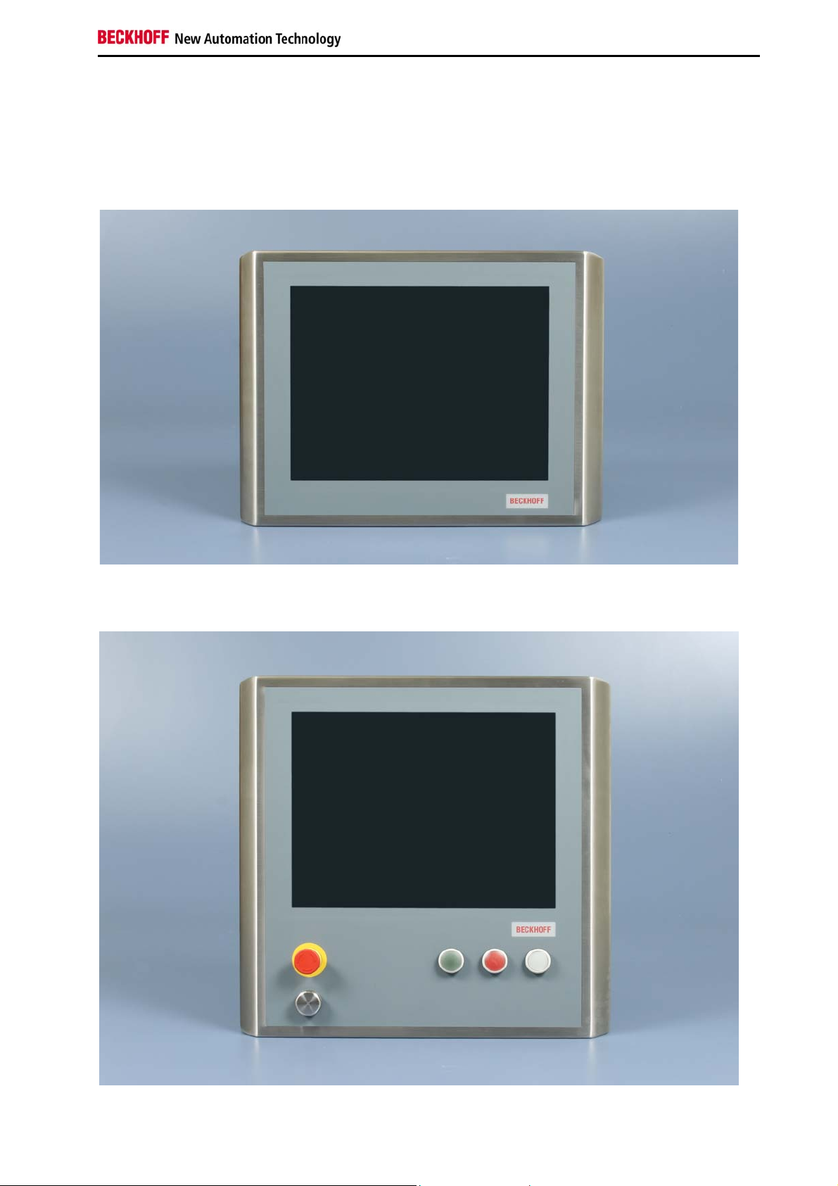
2.1 Product overview
Front view of CP790x-1400
Front view of CP790x-1401 with USB-port, emergency stop button and electromechanical push-buttons
CP790x-140x 7
Page 10

Product Description
The CP790x Control Panels in a stainless steel finish are control and display units that meet the strict
hygiene regulations for the food, packaging and medical industries as well as for clean rooms. The
stainless steel Panels with IP65 protection feature virtually gap less housing design with flush-mounted
touch screens. The housing geometry and an optimized frame profile allow liquids to run off and prevent
the accumulation of contamination. Further features, such as the resistance of the stainless steel surface
and the touch screen to cleaning agents and disinfectants, as well as the equipping of the display with a
splinter guard, cover all requirements for clean room applications.
The CP79xx stainless steel panels with DVI/USB Extended allow a distance of up to 50 m between
operating unit and PC. The stainless steel Control Panels are highly functional units with 12-, 15- or
19-inch touch panels. The range is completed by a stainless steel mounting arm adapter for adaptation to
steel pipes, which can be ordered as an option. Furthermore, the range is rounded off by customerspecific modifications, such as additional display sizes or the integration of emergency off and
electromechanical buttons, short-stroke keys and RFID readers under the front laminate as well as USB
ports.
The Stainless steel Control Panel offer the following benefits:
Flush mounted touch screen •
•
Stainless steel housing 1.4301, matt ground with grain size 240, protection class IP65
•
Front laminate with slide-in logo
•
Flush mounted integrated stainless steel 1.4301-backplane
•
Integrated DVI/USB extension technology:
– DVI-E and USB-E enable remote panel operation at a distance of up to 50 m from the PC
– DVI-E input is compatible to the standard DVI output of a PC
•
Connections in the range of the mounting arm adapter over 3 connectors IP65 for DVI, USB-E
and 24 V
•
USB-port, emergency stop button and electromechanical push-buttons in the front
(only CP790x-1401)
•
Connector 19-pin, IP65, for push buttons
• Optionally available: Beckhoff stainless steel mounting arm adapter C9900-M177 and C9900M178.
8 CP790x-140x
Page 11
Product Description
2.2 Appropriate Use
The CP790x Control Panel is designed for industrial application in machine and plant engineering. In
addition to the DVI/ USB interface, a TFT display and a touch screen are accommodated in a stainless
steel housing.
In the front of the Control Panel CP790x-1401, one USB-port, an emergency stop button (S1) and three
electromechanical push-buttons (S2-S4) are integrated. The Control Panel is installed at a mounting arm,
a rotatable mounting arm adapter is available.
Risk of explosion!
The Control Panel must not be used where there is a risk of explosion.
Danger
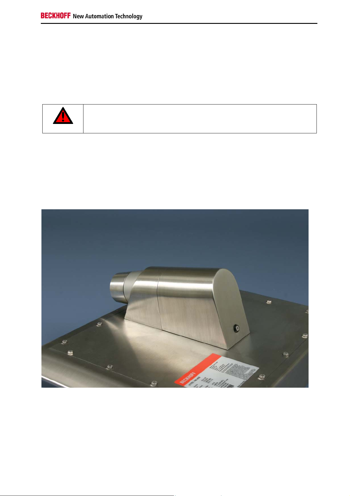
2.3 Opening the connection area
The connectors of the Control Panel are located at the rear side of the device.
If the Control Panel is fitted with a mounting arm adapter (order-option C9900-M177 or C9900-M178), the
connectors are located behind a cover (1). To get access to the connectors, the cover has to be removed:
First loosen the fixing screw (2) with an allen head key.
1
2
The cover now can be drawn off in direction of the arrow (see next picture).
CP790x-140x 9
Page 12
Product Description
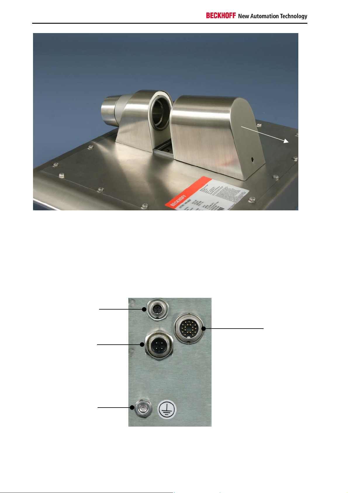
After opening the connection area you have access to the connectors of the Control Panel. The cables
with the connectors have to be pulled through the mounting arm tube before connecting them in the
connection area.
The installation of the cover takes place in reverse order.
2.4 Connections
CP790x-1400
X103
USB-E input
X101
DVI-E input
X102
Power Supply
Protective
Earthing
10 CP790x-140x
Page 13

Product Description
CP790x-1401
with USB-port, emergency stop button and electromechanical push-buttons in the front
X103
USB-E input
X101
DVI-E input
X102
Power Supply
Protective
Earthing
XS01
Emergency stop and
push-buttons
2.4.1 DVI-E Input (Digital Visual Interface-Extended) (X101)
X101
SG 19-pole M16 built-in-PCB-sold. IP67 BINDER (BINDER 09-0463-90-19 prod. 723 M16X0,75)
View solder connection sided
The DVI-E connection (X101) is used for transferring the video signal from the Industrial PC to the Control
Panel. The protection class of the circular plug-in connector accords to the IP67-standard.
The graphics signal is transferred directly via a DVI cable over a distance of 50 m max. Such a cable
length leads to strong distortion of the graphics signal on arrival at the Control Panel. The CP790x Control
Panel features a signal processor that restores the DVI signal. The PC requires a conventional DVI
output.
The transmission rate of the DDC file has to be limited
Note
At large distance between PC and Control Panel, the transmission rate of the DDC file
has to be limited.
See also chapter Setting the transmission rate.
Pin Signal Pin Signal
A Shield L IN_TMDS_C+
B IN_TMDS_2+ M GND
C GND N IN_TMDS_2-
D IN_TMDS_1- O IN_TMDS_1+
E GND P GND
F IN_TMDS_0- R IN_TMDS_0+
G GND S HPD_DVI
H + 5V_DVI T GND
I DDC DAT U IN_TMDS_C-
K I2C-CLK
CP790x-140x 11
Page 14

Product Description
2.4.2 Power Supply (X102)
X102
SG 4-pole M12 built-in-PCB-sold. IP67 BINDER (BINDER 09-3431-90-04 prod. 763 M12X1)
View solder connection sided
The power supply for the Control Panel is established via the 4-pole M12 socket (X102). The protection
class of the circular plug-in connector accords to the IP67-standard.
Pin Signal Pin Signal
1 + 24V 3 GND
2 NC 4 NC
2.4.3 USB-E Input (USB-Extended) (X103)
X103
SG 8-pole M9 built-in-PCB-sold. IP67 BINDER (BINDER 09-0427-30-08 prod. 712 M9X0,5)
View solder connection sided
The Control Panel is connected with the CU8800 USB to USB extended converter box via the USBExtended input (X103).
In order to realize a distance of 50 m without hubs, with USB extended the USB signal is converted so
that it can be transferred via 50 m CAT5 cables commonly used for Ethernet wiring. In the Control Panel
the signal is converted back to USB.
Pin Signal Pin Signal
1 NC 5 USB Tx-
2 USB Rx- 6 USB Tx+
3 USB Rx+ 7 15V USB_E
4 GND 8 GND
2.4.4 Protective Earthing
The low resistance protective earthing connection of the Control Panel is established via the ground bolt,
which is located in the connection area.
12 CP790x-140x
Page 15

Product Description
2.4.5 Connection Emergency stop and push-buttons CP790x-1401 (XS01)
In the front of the Control Panel CP790x-1401, an emergency stop button (S1) and three
electromechanical push-buttons (S2 - S4) are integrated. The buttons can be connected user-specific.
emergency stop
pushbutton S2
pushbutton S3
pushbutton S4
The connection of the emergency stop button and the electromechanical push-buttons are established via
the 19-pole M20 (XS01) connector in the connection area. The protection class of the circular plug-in
connector accords to the IP67-standard. For the accurate connection see chapter Wiring Diagram.
XS01
Circular plug-in connector 19-pole M20 built-in linear, IP67, Intercontec
(Intercontec A EG A 378 MR93 00 0032 000)
Take notice of the ampacity
The maximum ampacity of the pin for connecting the emergency stop button and the
Warning
electromechanical push-buttons is 100 mA at max. 35 V AC/ DC.
Male connector is provided
The male connector Intercontec A ST A 278 FR91 61 0035 000 is provided with the
Note
Control Panel.
Pin Signal Pin Signal
1 S1.12 11 LED red K1
2 S1.11 12 PE
3 S1.22 13 S4.14
4 S1.21 14 S4.22
5 S2.14 15 LED white K1
6 GND 16 NC
7 S2.22 17 NC
8 LED green K1 18 NC
9 S3.14 19 + 24V
10 S3.22
CP790x-140x 13
Page 16

Product Description
2.4.6 USB-Port at the Front (CP790x-1401)
USB-port
Screw cap
The Control Panel CP790x-1401 is provided with an additional USB-2.0-port.
The port is located at the front side of the Control Panel under a screw cap. The protection class accords
to the IP67-standard.
2.5 Connection Kits/ Connection Cables
One 4-pole power supply connector is provided with the Control Panel.
Optionally prefabricated connection cables for connecting the emergency-stop-button and the pushbuttons (XS01), as well as connection kits for the DVI-E/ USB-E connection are available.
2.5.1 Connection Cables Emergency Stop and Push-Buttons, optional
The following connection cables are available:
Connection Cables Cables for connecting Emergency Stop and Push-Buttons
C9900-K604 Plug-in connector 19-pole with connection cable 18 x 0.75 mm2,
second end open, length 10 m
C9900-K593 Plug-in connector 19-pole with connection cable 18 x 0.75 mm2,
second end open, length 20 m
C9900-K558 Plug-in connector 19-pole with connection cable 18 x 0.75 mm2,
second end open, length 30 m
14 CP790x-140x
Page 17

Product Description
2.5.2 Connection Kits for DVI-E/ USB-E connection, optional
The following connection kits are available:
Cable Set DVI-E/ USB-E connection
C9900-K434
C9900-K435
C9900-K436
C9900-K437
C9900-K438
C9900-K439
C9900-K440
Connection kit 3 m for CP79xx including:
3 m DVI cable, 3 m CAT5 cable for USB-E, USB to USB-E converter CU8800 for
mounting rail installation close to the PC and 1 m USB cable to connect the USB to
USB-E converter to the PC
Connection kit 5 m for CP79xx including:
5 m DVI cable, 5 m CAT5 cable for USB-E, USB to USB-E converter CU8800 for
mounting rail installation close to the PC and 1 m USB cable to connect the USB to
USB-E converter to the PC
Connection kit 10 m for CP79xx including:
10 m DVI cable, 10 m CAT5 cable for USB-E, USB to USB-E converter CU8800 for
mounting rail installation close to the PC and 1 m USB cable to connect the USB to
USB-E converter to the PC
Connection kit 20 m for CP79xx including:
20 m DVI cable, 20 m CAT5 cable for USB-E, USB to USB-E converter CU8800 for
mounting rail installation close to the PC and 1 m USB cable to connect the USB to
USB-E converter to the PC
Connection kit 30 m for CP79xx including:
30 m DVI cable, 30 m CAT5 cable for USB-E, USB to USB-E converter CU8800 for
mounting rail installation close to the PC and 1 m USB cable to connect the USB to
USB-E converter to the PC
Connection kit 40 m for CP79xx including:
40 m DVI cable, 40 m CAT5 cable for USB-E, USB to USB-E converter CU8800 for
mounting rail installation close to the PC and 1 m USB cable to connect the USB to
USB-E converter to the PC
Connection kit 50 m for CP79xx including:
50 m DVI cable, 50 m CAT5 cable for USB-E, USB to USB-E converter CU8800 for
mounting rail installation close to the PC and 1 m USB cable to connect the USB to
USB-E converter to the PC
CP790x-140x 15
Page 18

Installation
3 Installation
3.1 Transport and Unpacking
The specified storage conditions must be observed (see chapter Technical Data).
3.1.1 Transport
Despite the robust design of the unit, the components are sensitive to strong vibrations and impacts.
During transport, your Control Panel should therefore be protected from excessive mechanical stress.
Therefore, please use the original packaging.
Danger of damage to the unit
If the device is transported in cold weather or is exposed to extreme variations in
Attention
Prior to operation, the unit must be allowed to slowly adjust to room temperature. Should condensation
occur, a delay time of approximately 12 hours must be allowed before the unit is switched on.
temperature, make sure that moisture (condensation) does not form on or inside the
device.
3.1.2 Unpacking
Proceed as follows to unpack the unit:
1. Remove packaging.
2. Do not discard the original packaging. Keep it for future relocation.
3. Check the delivery for completeness by comparing it with your order.
4. Please keep the associated paperwork. It contains important information for handling the unit.
5. Check the contents for visible shipping damage.
If you notice any shipping damage or inconsistencies between the contents and your order, you should
notify Beckhoff Service.
16 CP790x-140x
Page 19

Mounting
4 Mounting
For mounting the Control Panel there are 6 threaded holes M6 x 6 mm in the range of the mounting arm
adapter at the rear side of the chassis (also see chapter Assembly dimensions).
Optionally the Control Panel can be mounted with a mounting arm adapter (order option).
4.1 Mounting arm installation
Depending on the order option the mounting arm can be installed from the bottom or from the top.
Order-Option Description
C9900-M177
C9900-M178
4.1.1 Welding the mounting arm tube
The junction of the mounting arm adapter has to be frozen with the customized mounting arm tube.
The picture shows the junction of the mounting arm adapter (1) and a customized mounting arm tube (2),
which was accurately frozen with the junction.
Rotatable mounting arm adapter for Control Panel CP790x-140x
Stainless steel 1.4301, matt ground, mounting arm installation from the bottom
Rotatable mounting arm adapter for Control Panel CP790x-140x
Stainless steel 1.4301, matt ground, mounting arm installation from the top
2
1
Optionally a ready-for-use mounting arm frozen with the mounting arm adapter is available:
Order-Option Description
C9900-M167
Mounting arm frozen with mounting arm adapter, 150 cm length,
Stainless steel 1.4301, matt ground.
Anti-twist protection
The mounting arm adapter is fitted with an anti-twist protection to avoid over winding
Note
CP790x-140x 17
the Control Panel and damaging the connecting cables.
Page 20

Mounting
4.1.2 Mounting the O-rings
The junction of the mounting arm adapter has to be fitted with the two red O-rings (see picture).
Mounting with PTFE-grease
Use assembly PTFE-grease for mounting arm installation.
Attention
In order to ensure better mobility of the mounting arm adapter, lubricate the O-rings and all parts which
have contact with the O-rings with the PTFE-grease. Lubricate a thin film of grease with a palette-knife or
a paint brush.
CAUTION
Note safety data sheet!
Please note the information in the safety data sheet for the PAO-PTFE-assembly
grease.
18 CP790x-140x
Page 21

Mounting
4.1.3 Mounting the mounting arm
Before you can mount the mounting arm at the Control Panel, the screw (1) which fixes the adapter (2)
has to be unscrewed and taken out completely.
O-rings
1
2
The picture shows the assembly of the rotatable mounting arm adapter, which first must be frozen with
the customized mounting arm (see chapter Welding the mounting arm tube).
Now the adapter is inserted in direction of the arrow all the way to the stop. Take care not to damage the
two red O-rings!
1
The adapter now has to be fixed with the screw (1).
CP790x-140x 19
Page 22

Mounting
4.2 Connecting the Control Panel
Risk of explosion!
The Control Panel must never be connected or disconnected in an area that is subject to
Danger
Attention
4.2.1 Connecting cables
The connections are located at the rear of the Control Panel and are documented in the chapter
Connections.
explosion hazard!
The mains plug must be disconnected
Please read the documentation for the external devices prior to connecting them!
During thunderstorms, plug connector must neither be inserted nor removed!
When disconnecting a plug connector, always handle it at the plug. Do not pull the cable!
When connecting cables to the Control Panel, please adhere to the following order:
• Disconnect the Control Panel from the power supply.
• Connect all cables at the Control Panel and at the devices to be connected.
• Ensure that all screw connections between connectors and sockets are tight!
• Reconnect all devices to the power supply.
4.2.2 Protective Earthing
The low resistance protective earthing connection of the Control Panel is established via the ground bolt,
which is located in the connection area.
20 CP790x-140x
Page 23

Operating Instructions
5 Operating Instructions
5.1 Switching the Control Panel on and off
5.1.1 Switching on
The Control Panel does not have its own mains power switch. As soon as the power supply is switched
on the Control Panel is activated.
5.1.2 Shutting down and switching off
Control software such as is typically used on Industrial PCs permits various users to be given different
rights. A user who may not close software may also not switch the Industrial PC off, since data can be
lost from the storage medium by switching off while software is running.
First shut down, then switch off!
If the Industrial PC is switched off as the software is writing a file to the storage
Warning
medium, the file will be destroyed. Control software typically writes something to the
storage medium every few seconds, so that the probability of causing damage by
switching off while the software is running is very high.
Switch off power supply
When you have shut down the Industrial PC, you have to switch off power supply for at
Warning
least 10 seconds before rebooting the system.
After resetting power supply the Industrial PC will start booting automatically.
5.2 Operation
The operation of the Control Panel occurs via the Touch Screen.
Risk of damaging the Touch Screen
The touch screen may only be actuated by finger tips or with the touch screen pen. The
Warning
5.2.1 Setting the transmission rate
At large distance between PC and Control Panel, the transmission rate of the DDC file has to be limited.
The DDC file is transmitted from the Control Panel to the PC in order to transfer the display information
like timing and resolution.
The video bios of the graphic card or, using the on-board graphic, the video bios of the motherboard
contains the definition of the transmission rate for the DDC file. This value has to be 50 kHz or less.
Otherwise the screen is not displayed or not until windows is started.
operator may wear gloves but there must be no hard particles such as metal shavings,
glass splinters embedded in the glove.
Windows graphic drivers also include a value for the transmission rate of the DDC file.
If Windows is running and no image is displayed, then use a graphic driver with a value of 50 kHz or less
for DDC file transmission.
CP790x-140x 21
Page 24

Operating Instructions
5.2.2 Emergency stop button and electromechanical push-buttons in the front
In the front, the Control Panel CP790x-1401 is equipped with an emergency stop button (S1) and three
push-buttons (S2 – S4), which can be connected user-specific.
emergency stop
button (S1)
pushbutton S2
pushbutton S3
pushbutton S4
5.3 Servicing and maintenance
5.3.1 Cleaning
Disconnect power supply
Switch off the device and all connected devices, and disconnect the device from the
DANGER
The device can be cleaned with a soft, damp cleaning cloth. Do not use any aggressive cleaning
materials, thinners, scouring material or hard objects that could cause scratches.
5.3.2 Maintenance
The Control Panel is maintenance-free.
power supply.
5.4 Emergency procedures
In case of fire, the Control Panel should be extinguished with powder or nitrogen.
5.5 Shutting down
5.5.1 Disposal
Observe national electronics scrap regulations
Observe the national electronics scrap regulations when disposing of the device.
Note
In order to dispose of the device, it must be removed and fully dismantled:
• Housing components (polycarbonate, polyamide (PA6.6)) are suitable for plastic recycling.
• Metal parts can be sent for metal recycling.
• Electronic parts such as disk drives and circuit boards must be disposed of in accordance with
national electronics scrap regulations.
22 CP790x-140x
Page 25

Troubleshooting
6 Troubleshooting
Pixel errors
Pixel errors in the TFT display are production-caused and represent no complaint-
Note
Fault Cause Measures
reason!
The Control Panel shows no
function
Computer boots, software starts,
but control does not operate
correctly
No screen Transmission rate is too high when
USB error while TwinCAT access
via USB
The Control Panel functions only
partially or only part of the time, e.g.
no or dark picture
No power supply to the Control
Panel/ Industrial PC
Cable not connected
Cause of the fault is either in the
software or in parts of the plant
outside the Industrial PC
using DVI cables longer than 20 m
Cycle time in TwinCAT is set on
10 ms (standard)
Faulty backlight in the display
Defective components in the
Control Panel
Check power supply cable
1. Correctly connect cable
2. Call Beckhoff Service
Call the manufacturer of the
machine or the software
Limit transmission rate for
DDC file to 50 kHz
Increase the cycle time up to
50 ms till 80 ms
Call Beckhoff Service
Call Beckhoff Service
CP790x-140x 23
Page 26

Assembly dimensions
7 Assembly dimensions
Notice mounting orientation
The assembly of the unit must take place with the orientation diagrammed here.
Warning
24 CP790x-140x
Page 27

Assembly dimensions
Notice mounting orientation
The assembly of the unit must take place with the orientation diagrammed here.
Warning
CP790x-140x 25
Page 28

Assembly dimensions
Notice mounting orientation
The assembly of the unit must take place with the orientation diagrammed here.
Warning
26 CP790x-140x
Page 29

Assembly dimensions
Notice mounting orientation
The assembly of the unit must take place with the orientation diagrammed here.
Warning
CP790x-140x 27
Page 30

Assembly dimensions
Notice mounting orientation
The assembly of the unit must take place with the orientation diagrammed here.
Warning
28 CP790x-140x
Page 31

Assembly dimensions
Notice mounting orientation
The assembly of the unit must take place with the orientation diagrammed here.
Warning
CP790x-140x 29
Page 32

Assembly dimensions
Notice mounting orientation
The assembly of the unit must take place with the orientation diagrammed here.
Warning
30 CP790x-140x
Page 33

Assembly dimensions
Notice mounting orientation
The assembly of the unit must take place with the orientation diagrammed here.
Warning
CP790x-140x 31
Page 34

Assembly dimensions
Notice mounting orientation
The assembly of the unit must take place with the orientation diagrammed here.
Warning
32 CP790x-140x
Page 35

Wiring Diagram Emergency stop button and push-buttons
8 Wiring Diagram Emergency stop button and push-buttons
CP790x-140x 33
Page 36

Technical Data
9 Technical Data
Risk of explosion!
Do not use the Control Panel in areas of explosive hazard!
Danger
Pixel errors
Pixel errors in the TFT display are production-caused and represent no complaint-
Note
Product name CP790x-140x
Dimensions (B x H x T) See chapter Assembly dimensions
Weight without/ with
mounting arm adapter
Supply voltage 24 V
Power consumption app. 14 W with 12“ Display
UL-compliance
Interfaces CP790x-1400 1 x DVI-E interface
Interfaces CP790x-1401 1 x DVI-E interface
Protection class IP65
Shock resistance
(Sinusoidal vibration)
Shock resistance
(Shock)
EMC compatibility Resistance to interference conforms to EN 61000-6-2
EMC compatibility Emission of interference conforms to EN 61000-6-4
Permissible ambient temperature 0°C to +55°C (operation)
Permissible relative humidity to 95%, no condensation
Transport and storage The same values for atmospheric humidity and shock resistance are
Certifications CE, UL
reason!
CP7901-1400: 5.3 kg/ 7.2 kg
CP7901-1401: 7.0 kg/ 8.9 kg
CP7902-1400: 7.2 kg/ 9.1 kg
CP7902-1401: 8.9 kg/ 10.8 kg
CP7903-1400: 10.6 kg/ 12.5 kg
CP7903-1401: 12.3 kg/ 14.2 kg
(20.4 – 28.8 VDC)
DC
app. 25 W with 15“ Display
app. 32 W with 19“ Display
• Using a power supply class 2 or
• Fuse protection with 4 A, according to UL 60950.2
chapter 2.5, table 2C
1 x USB-E interface
1 x USB-E interface
Additional: USB-port, emergency stop button and electromechanical
push-buttons in the front
EN 60068-2-6: 10 to 58 Hz: 0.035 mm
58 to 500 Hz: 0.5 G (~ 5 m/ s
2
)
EN 60068-2-27: 5 G (~ 50 m/ s2), duration: 30 ms
-25°C to +65°C (transport/ storage)
to be observed during transport and storage as in operation. Suitable
packaging of the Panel PC can improve the resistance to impact
during transport.
34 CP790x-140x
Page 37

Appendix
10 Appendix
10.1 Beckhoff Support and Service
Beckhoff and their partners around the world offer comprehensive support and service, making available
fast and competent assistance with all questions related to Beckhoff products and system solutions.
10.1.1 Beckhoff branches and partner companies
Please contact your Beckhoff branch office or partner company for local support and service on Beckhoff
products!
The contact addresses for your country can be found in the list of Beckhoff branches and partner
companies: www.beckhoff.com
10.1.2 Beckhoff company headquarters
Beckhoff Automation GmbH
Eiserstraße 5
33415 Verl
Germany
. You will also find further documentation for Beckhoff components there.
Phone: + 49 (0) 5246/963-0
Fax: + 49 (0) 5246/963-198
E-mail: info@beckhoff.de
Web: http://www.beckhoff.de/
Beckhoff Support
Support offers you comprehensive technical assistance, helping you not only with the application of
individual Beckhoff products, but also with other, wide-ranging services:
• world-wide support
• design, programming and commissioning of complex automation systems
• and extensive training program for Beckhoff system components
Hotline: + 49 (0) 5246/963-157
Fax: + 49 (0) 5246/963-9157
E-mail: support@beckhoff.com
Beckhoff Service
The Beckhoff Service Center supports you in all matters of after-sales service:
• on-site service
• repair service
• spare parts service
• hotline service
Hotline: + 49 (0) 5246/963-460
Fax: + 49 (0) 5246/963-479
E-mail: service@beckhoff.com
If servicing is required, please quote the project number of your product.
CP790x-140x 35
Page 38

Appendix
10.2 Approvals for USA and Canada
10.3 FCC Approvals for the United States of America
FCC: Federal Communications Commission Radio Frequency Interference Statement
This equipment has been tested and found to comply with the limits for a Class A digital device, pursuant
to Part 15 of the FCC Rules. These limits are designed to provide reasonable protection against harmful
interference when the equipment is operated in a commercial environment. This equipment generates,
uses, and can radiate radio frequency energy and, if not installed and used in accordance with the
instruction manual, may cause harmful interference to radio communications. Operation of this equipment
in a residential area is likely to cause harmful interference in which case the user will be required to
correct the interference at his own expense.
Technical modifications
Technological changes to the device may cause the loss of the FCC approval.
Note
10.4 FCC Approval for Canada
FCC: Canadian Notice
This equipment does not exceed the Class A limits for radiated emissions as described in the Radio
Interference Regulations of the Canadian Department of Communications.
36 CP790x-140x
 Loading...