

Page 1
AS1000
Stepper motor
Operating instructions | EN
2019/04/09 | Version: 3.7
Page 2

Page 3

1 Documented motors
Documented motors
AS10xx-xxxx Standstill
torque [Nm]
AS1010-0000 0,38 1,0 0,056
AS1020-0xxx 0,5 1,0 0,074 0,39
AS1030-0000 0,6 1,5 0,21 0,68
AS1050-0xxx 1,2 5,0 0,36 1,00
AS1060-xxxx 5,0 5,0 3,0 2,85
Rated current
[A]
Rotor moment
of inertia [kg
cm²]
Resolution
[Steps]
1,8° / 200 Steps
Weight [kg]
0,31
Stepper motor 3Version: 3.7
Page 4

Table of contents
Table of contents
1 Documented motors..................................................................................................................................3
2 Foreword ....................................................................................................................................................7
2.1 Notes on the documentation..............................................................................................................7
2.2 Documentation Issue Status..............................................................................................................8
2.3 Appropriate use .................................................................................................................................9
3 Guidelines and Standards ......................................................................................................................10
3.1 EC Declaration of Conformity ..........................................................................................................10
4 Safety........................................................................................................................................................11
4.1 Personnel qualification ....................................................................................................................11
4.2 Description of safety symbols..........................................................................................................11
4.3 Special safety instructions for AS1000 ............................................................................................12
5 Handling ...................................................................................................................................................13
5.1 Transport .........................................................................................................................................13
5.2 Packaging........................................................................................................................................13
5.3 Storage ............................................................................................................................................13
5.4 Maintenance / Cleaning...................................................................................................................14
5.5 Disposal...........................................................................................................................................14
6 Product identification..............................................................................................................................15
6.1 AS1000 supply schedule .................................................................................................................15
6.2 AS1000 name plate .........................................................................................................................15
6.3 AS1000 type key .............................................................................................................................16
7 Technical description..............................................................................................................................17
7.1 Design of the motors .......................................................................................................................17
7.2 General technical data.....................................................................................................................18
7.3 Standard features ............................................................................................................................18
7.3.1 Style................................................................................................................................. 18
7.3.2 Shaft end, A-side ............................................................................................................. 19
7.3.3 Flange.............................................................................................................................. 19
7.3.4 Connection technology .................................................................................................... 19
7.3.5 Feedback system............................................................................................................. 19
7.4 Options ............................................................................................................................................19
7.5 Transport, assembly and disassembly ............................................................................................19
8 Mechanical installation ...........................................................................................................................20
8.1 Important notes................................................................................................................................20
8.2 Installing the stepper motor .............................................................................................................21
8.3 Installing the incremental encoder (type 2420)................................................................................21
8.3.1 Technical data of the encoder ......................................................................................... 21
8.4 Planetary gear .................................................................................................................................22
8.4.1 Technical data of the planetary gear units....................................................................... 22
8.4.2 Installing the planetary gear............................................................................................. 22
9 Electrical installation...............................................................................................................................23
9.1 Important notes................................................................................................................................23
Stepper motor4 Version: 3.7
Page 5

Table of contents
9.2 Connection of motors with preassembled cables ............................................................................24
9.3 Electrical components .....................................................................................................................25
9.3.1 Motor connector............................................................................................................... 25
9.3.2 Encoder connector........................................................................................................... 25
9.4 Connection diagram KL2531 ...........................................................................................................26
9.5 Connection diagram KL2541 ...........................................................................................................27
9.6 Connection diagram EL7031 ...........................................................................................................28
9.7 Connection diagram EL7041 ...........................................................................................................29
9.8 Connection diagram EL7037 ...........................................................................................................30
9.9 Connection diagram EL7047 ...........................................................................................................31
9.10 Connection diagram EP7041-3002 .................................................................................................32
10 Commissioning........................................................................................................................................33
10.1 Important notes................................................................................................................................33
10.2 Guide for commissioning .................................................................................................................33
10.3 Troubleshooting...............................................................................................................................34
11 Technical data..........................................................................................................................................35
11.1 Step mode and limit speeds ............................................................................................................35
11.2 AS1010-0000...................................................................................................................................36
11.2.1 Characteristic curve diagram for AS1010-0000............................................................... 37
11.2.2 Dimensional drawing AS1010-0000 ................................................................................ 38
11.3 AS1020-0xxx ...................................................................................................................................39
11.3.1 Characteristic curve diagram for AS1020-0xxx ............................................................... 40
11.3.2 Dimensional drawing AS1020-0xxx ................................................................................. 41
11.4 AS1030-0000...................................................................................................................................42
11.4.1 Characteristic curve diagram for AS1030-0000............................................................... 43
11.4.2 Dimensional drawing AS1030-0000 ................................................................................ 44
11.5 AS1050-0xxx ...................................................................................................................................45
11.5.1 Characteristic curve diagram for AS1050-0xxx ............................................................... 46
11.5.2 Dimensional drawing AS1050-0xxx ................................................................................. 47
11.6 AS1060-xxxx ...................................................................................................................................48
11.6.1 Characteristic curve diagram for AS1060-xxxx................................................................ 49
11.6.2 Dimensional drawing AS1060-0xxx ................................................................................ 50
11.6.3 Dimensional drawing AS1060-1xxx ................................................................................. 51
12 Appendix ..................................................................................................................................................52
12.1 Support and Service ........................................................................................................................52
Stepper motor 5Version: 3.7
Page 6

Table of contents
Stepper motor6 Version: 3.7
Page 7

Foreword
2 Foreword
2.1 Notes on the documentation
This description is only intended for the use of trained specialists in control and automation engineering who
are familiar with the applicable national standards.
It is essential that the documentation and the following notes and explanations are followed when installing
and commissioning the components.
It is the duty of the technical personnel to use the documentation published at the respective time of each
installation and commissioning.
The responsible staff must ensure that the application or use of the products described satisfy all the
requirements for safety, including all the relevant laws, regulations, guidelines and standards.
Disclaimer
The documentation has been prepared with care. The products described are, however, constantly under
development.
We reserve the right to revise and change the documentation at any time and without prior announcement.
No claims for the modification of products that have already been supplied may be made on the basis of the
data, diagrams and descriptions in this documentation.
Trademarks
Beckhoff®, TwinCAT®, EtherCAT®, EtherCAT G®, EtherCAT G10®, EtherCAT P®, Safety over EtherCAT®,
TwinSAFE®, XFC®, und XTS® and XPlanar®, are registered trademarks of and licensed by Beckhoff
Automation GmbH.
Other designations used in this publication may be trademarks whose use by third parties for their own
purposes could violate the rights of the owners.
Patent Pending
The EtherCAT Technology is covered, including but not limited to the following patent applications and
patents:
EP1590927, EP1789857, EP1456722, EP2137893, DE102015105702
with corresponding applications or registrations in various other countries.
EtherCAT® is registered trademark and patented technology, licensed by Beckhoff Automation GmbH,
Germany
Copyright
© Beckhoff Automation GmbH & Co. KG, Germany.
The reproduction, distribution and utilization of this document as well as the communication of its contents to
others without express authorization are prohibited.
Offenders will be held liable for the payment of damages. All rights reserved in the event of the grant of a
patent, utility model or design.
Stepper motor 7Version: 3.7
Page 8

Foreword
2.2 Documentation Issue Status
Origin of the document
This documentation was originally written in German. All other languages are derived from the German
original.
Product features
Only the product features specified in the current user documentation are valid. Further information given on
the product pages of the Beckhoff homepage, in emails or in other publications is not authoritative.
Issue Comment
3.7 Chapter update:
Documentation Issue Status; EC Declaration of conformity; Safety; Planetary gear; Motor
connector; Encoder connector; Connection diagrams
3.6 Chapter update:
EC Declaration of conformity; Disposal 4.5
3.5 Chapter update:
Connection diagram AS1xxx 9.4 – 9.10
3.4 Chapter update:
Technical data AS1010 – AS1060 11.2 – 11.6
3.3 Chapter update:
Foreword 1.0 and Safety 3.0; 2.0
3.2 Chapter update:
7.3.1; 10.1
3.1 New chapter:
Documented motors
Chapter update:
7.4; 8.3.1; 8.4; 8.5; 8.6; 8.7; 8.8; 8.9; 10.2; 10.3; 10.4; 10.5; 10.6
3.0 General revision
2.2 Chapter revision:
• Product description – Dimensions
• Installation and operation - Installation
2.1 Chapter revision:
• Product description – Technical data
Stepper motor8 Version: 3.7
Page 9

Foreword
2.3 Appropriate use
Stepper motors of the AS1000 series are mainly intended as actuators for handling equipment, textile
machines, machine tools, packaging machines and similar machines. The motors of the AS1000 series are
exclusively intended for operation based on speed and / or position control via stepper motor output stages
from Beckhoff Automation GmbH & Co. KG.
CAUTION
Danger for persons, the environment or equipment
The motors are operated in the drive system in conjunction with Beckhoff stepper motor output stages.
Please observe the entire documentation which consists of:
• AS1000 documentation (this manual)
• Complete documentation (online and paper) for Beckhoff stepper motor output stages available at
www.beckhoff.com.
• Complete machine documentation (provided by the machine manufacturer)
WARNING
Caution - Risk of injury!
Electronic equipment is not fail-safe. The machine manufacturer is responsible for ensuring
that the connected motors and the machine are brought into a safe state in the event of a
fault in the drive system.
Special safety instructions for AS1000!
For the installation and commissioning of the components the observance of the general and special safety instructions [}12] and explanations is essential. Carefully read the chapters carefully.
The stepper motors from the AS1000 series are designed for installation as components in electrical
systems or machines and may be operated only as integrated system or machine components.
The motors may only be operated under the ambient conditions defined in this documentation.
Stepper motor 9Version: 3.7
Page 10

Guidelines and Standards
3 Guidelines and Standards
CAUTION
Danger for persons, the environment or equipment
Stepper motors of the AS1000 series are not products as defined by the EC Machinery Directive. Operation of the stepper motors in machines or systems is only permitted once the machine or system manufacturer has provided evidence of CE conformity of the complete machine or system.
3.1 EC Declaration of Conformity
Provision of EU Declaration of Conformity:
Beckhoff Automation GmbH & Co. KG will be glad to provide you with EU declarations of conformity
and manufacturer's declarations for all products upon request to info@beckhoff.com.
Stepper motor10 Version: 3.7
Page 11
Safety
4 Safety
4.1 Personnel qualification
This description is only intended for trained specialists in control, automation and drive engineering who are
familiar with the applicable national standards.
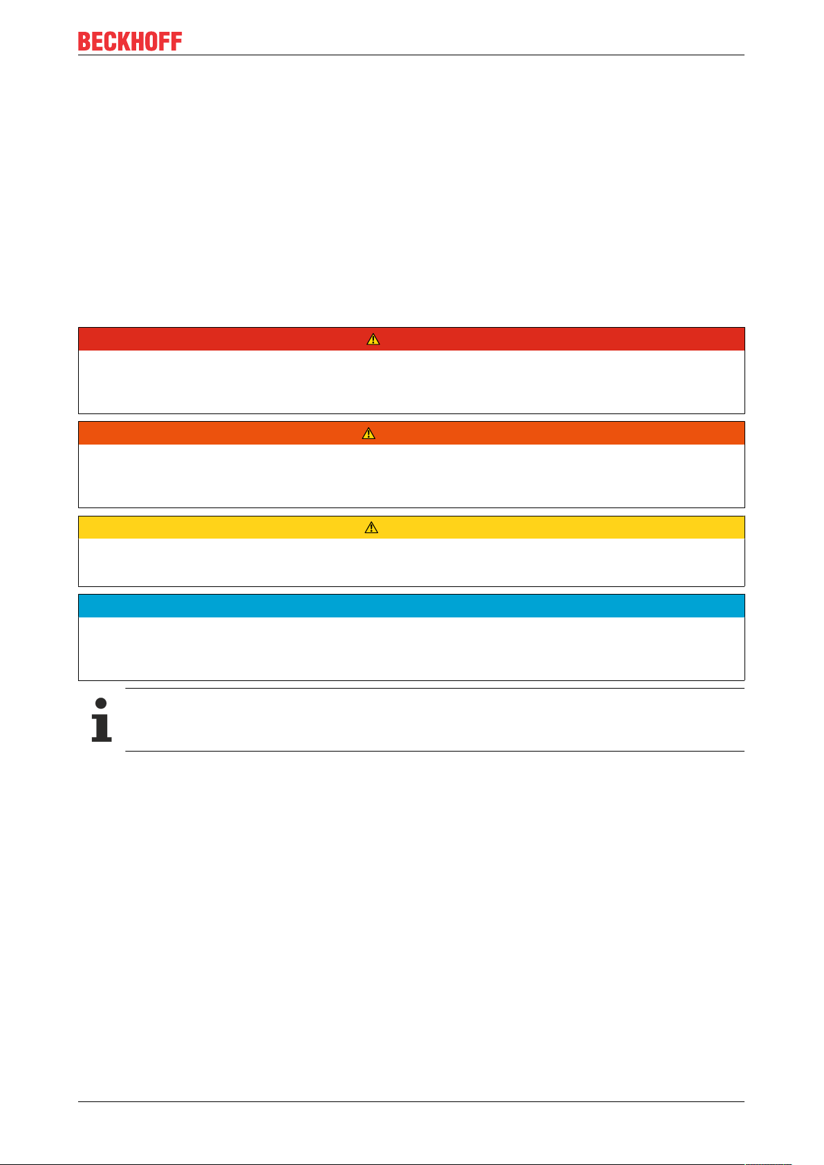
4.2 Description of safety symbols
The following safety symbols and associated safety instructions are used in this document. These safety
instructions must be read and followed.
DANGER
Serious risk of injury!
Failure to follow the safety instructions associated with this symbol directly endangers the life and health of
persons.
WARNING
Caution – Risk of injury!
Failure to follow the safety instructions associated with this symbol endangers the life ans health of persons.
CAUTION
Personal injuries!
Failure to follow the safety instructions associated with this symbol can be lead to injuries to persons.
NOTE
Damage to the enviroment or devices!
Failure to follow the safety instructions associated with this symbol can be lead to damage to the environment or equipment.
Tip or pointer
This symbol indicates information that contributes to better understanding.
Stepper motor 11Version: 3.7
Page 12

Safety
4.3 Special safety instructions for AS1000
The safety instructions are designed to avert danger and must be followed during installation,
commissioning, production, troubleshooting, maintenance and trial or test assemblies. The stepper motors of
the AS1000 series are not designed for stand-alone operation and are always installed in a machine or
system. After installation, the documentation the documentation and the safety instructions provided by the
machine manufacturer must be read and applied.
WARNING
Serious risk of injury through hot surfaces!
• The surface temperature may exceed 100 °C, resulting in a risk of burns.
• Avoid touching the housing during or shortly after operation.
• Leave the stepper motor to cool down for at least 15 minutes after it is switched off.
• Use a thermometer to check whether the surface has cooled down sufficiently.
NOTE
Danger for persons, the environment or equipment
• Please read this manual carefully before using the stepper motor. Follow all safety instructions. If there
are sections you do not understand, please contact your sales office and refrain from working with the
stepper motor.
• Only well trained, qualified electricians with sound knowledge of drive equipment may work on the device.
• During installation, adhere to the ventilation clearances and climatic conditions. Further information can
be found in the "Technical data" and "Mechanical installation" sections.
• If a stepper motor is installed in a machine it must not be commissioned until proof of compliance of the
machine with the latest version of the EC Machinery Directive has been provided. This includes all relevant harmonized standards and regulations required for implementation of this Directive in national legislation.
Stepper motor12 Version: 3.7
Page 13
5 Handling
5.1 Transport
• Climate category: 2K3 according to EN 60721
• Transport temperature: -25 °C - +70 °C, max. fluctuation 20 K/hour
• Transport humidity: relative humidity 5% - 95%, non-condensing
• The stepper motor may only be transported by qualified personnel and in the manufacturer's original
recyclable packaging.
• Avoid hard impacts, particularly at the shaft end.
• If the packaging is damaged, check the motor for visible damage. Inform the transport company and, if
necessary, the manufacturer.
5.2 Packaging
• Cardboard packaging
Handling
Motor without installed gear unit
Motor type Max. stacking height
AS1010 5
AS1020 5
AS1030 5
AS1050 5
AS1060 3
Motor with installed gear unit
Motor and gear type Max. stacking height
AS1030 with AG1000-PM052.00x 3
AS1050 with AG1000-PM052.00x 3
AS1060 with AG1000-PM081.00x 2
5.3 Storage
• Climate category: 2K3 according to EN 60721
• Storage temperature: -25 °C - +55 °C, max. fluctuation 20 K/hour
• Air humidity: relative humidity 5% - 95%, non-condensing
• Max. stacking height: see table Packaging
• Storage time: without limitation
• Store only in the manufacturer’s original recyclable packaging.
Stepper motor 13Version: 3.7
Page 14

Handling
5.4 Maintenance / Cleaning
• Maintenance and cleaning only by qualified personnel.
• The ball bearings have a grease filling. The actual life of the bearings depends on various factors,
including the radial load, shear load, operating temperature and motor speed.
• Check the motor for bearing noise every 2,500 operating hours or once per year. If any noises are
heard, stop the operation of the motor. The bearings must be replaced.
• Opening the motor invalidates the warranty.
• Clean the housing with isopropanol or similar.
NOTE
Destruction of the stepper motor
Never immerse or spray the stepper motor.
5.5 Disposal
In accordance with the WEEE 2012/19/EU Directives we take old devices and accessories back for
professional disposal, provided the transport costs are taken over by the sender.
Send the devices with the note “For disposal” to:
Beckhoff Automation GmbH & Co. KG
Huelshorstweg 20
D-33415 Verl
Stepper motor14 Version: 3.7
Page 15
6 Product identification
6.1 AS1000 supply schedule
Please check that the delivery includes the following items:
• AM1000 series motor
• Connecting cable with 4-pin M12 connector (underside firmly connected)
• Online documentation at www.beckhoff.de
Scope of supply
The M12 mating connectors are not included!
The following accessories are available on request:
• Second shaft end for AS1020, AS1050 and AS1060
• Encoder with connection cable and 5-pin, screened M12 socket
• Preassembled motor and feedback cable
• Planetary gear, AG1000 series
Product identification
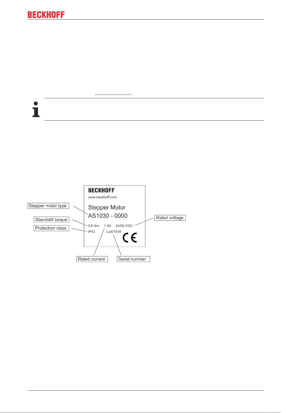
6.2 AS1000 name plate
Stepper motor 15Version: 3.7
Page 16
Product identification
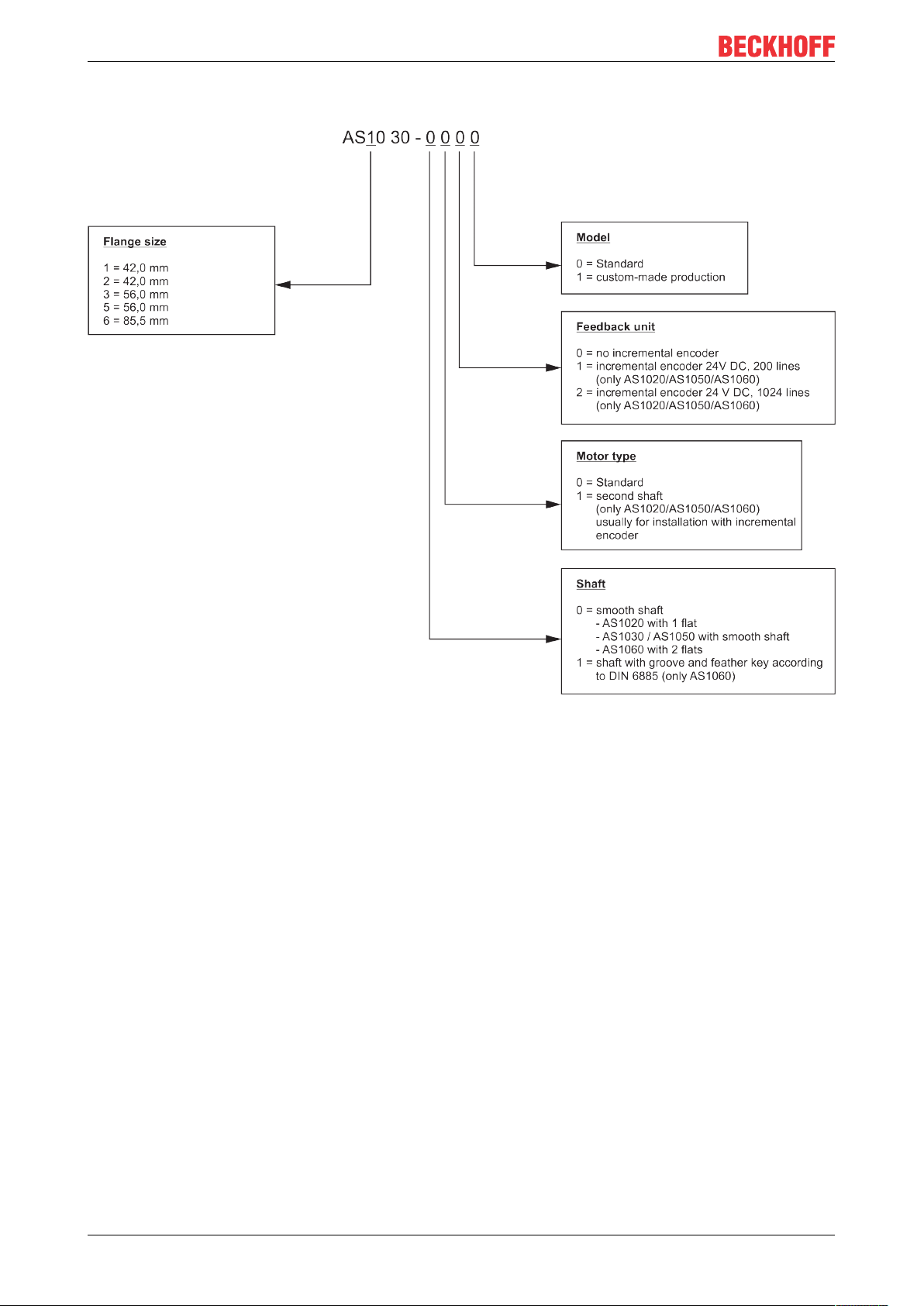
6.3 AS1000 type key
Stepper motor16 Version: 3.7
Page 17

Technical description
7 Technical description
7.1 Design of the motors
Beckhoff stepper motors of the AS1000 series are synchronous motors with a large number of poles. They
are classified as direct drives. The stepper motors of the AS1000 series are characterized by a high holding
torque and very good positioning capability. Thanks to sophisticated control of the stator windings in full-step
or micro-step mode, individual steps or partial steps can be executed directly without a feedback system.
This feature distinguishes stepper motors from servomotors, thus representing a cost-effective alternative
approach. Excessive acceleration and fast load cycles can result in the stepper motor being unable to follow
the rotating field and therefore "losing steps". The encoder option can improve matters in this situation.
The stepper motor has its highest torque in the lower speed range. At standstill, the stepper motor is
characterized by a very high holding torque. In many applications, this eliminates the need for a holding
brake. In the Beckhoff stepper motor terminals a suitable current curve can be stored for any speed or load
profile. This serves to optimally adapt the thermal load of the motor. Beckhoff stepper motors are used as
actuators or auxiliary axes in machine construction and automation applications. In conjunction with the
stepper motor output stages and the Beckhoff TwinCAT automation system, this facilitates integration of
cost-effective axes into the overall application. In order to simplify the electrical connection, the stepper
motors are equipped with pre-assembled plug connectors. Planetary gear units, incremental encoders and
pre-assembled connection cables are available as accessories.
Stepper motor 17Version: 3.7
Page 18

Technical description
7.2 General technical data
Insulation class Class B (130°C) according to IEC60085
Temperature change at rated current Max. 80 K
Insulation resistance ≥ 100 MΩ
Permissible ambient temperature (operation) -10°C to +50°C
Permissible ambient temperature (transport/
storage)
Permissible air humidity 20% to 90%, non-condensing
Permissible level of contamination Contamination level 2 according to EN60204/
Corrosion protection Under extreme operating conditions, special
Permissible operating altitude Up to 1000 m above sea level
Maximum cable length between motor and
terminal
Special operating conditions The applicability of the Beckhoff AS1000 stepper
Correct installation position Horizontal or vertical
Ventilation Ensure adequate ventilation of the motors.
Protection class (doesn´t apply to the shaft
bushing)
-25℃ to +70℃
EN50178
measures must be agreed with the manufacturer, and
implemented by the user.
10 m
motor is to be determined for each individual case.
Application in harsh operating or environmental
conditions requires coordination between
manufacturer and user.
AS1010 – AS1050: IP43
AS1060: IP20
7.3 Standard features
7.3.1 Style
The design of the AS1010 and AS1020 stepper motors is intended for flange mounting based on installation
types IM B14, IM V18 and IM V19.
The design of the AS1030/AS1050 and AS1060 stepper motors is intended for flange mounting based on
installation types IM B5, IM V1 and IM V3.
The permitted mounting positions are specified in the technical data.
NOTE
Destruction of the motors
Installation positions IM V1 and IM V3 may result in liquid entering the motor and associated damage.
Stepper motor18 Version: 3.7
Page 19

Technical description
7.3.2 Shaft end, A-side
The force transfer is friction-locked (backlash-free), via a clutch, via the cylindrical shaft end A, or optionally
as a form-locking connection via a feather key groove according to DIN6885.
Radial force
If the motors drive via pinions or toothed belts, then high radial forces will occur.
Axial force
Axial forces occur when assembling pinions or pulleys on the shaft.
Coupling
Double-coned collets, possibly in association with metal bellows couplings, have proven themselves as
excellent, zero backlash coupling elements.
7.3.3 Flange
Flange dimensions according to IEC standard, fit j6, accuracy according to DIN 60034-7
Tolerance class: N
7.3.4 Connection technology
The motors are equipped with connecting cables (300 mm) and M12 connectors for the power supply and
the feedback signals (encoders only).
The mating connectors are not included in the scope of supply. Ready-made extension cables in different
lengths are available as accessories.
7.3.5 Feedback system
Feedback system Resolution Comment
Incremental encoders 200 increments Only for AS1020/AS1050/
AS1060
Incremental encoders 1024 increments Only for AS1020/AS1050/
AS1060
7.4 Options
Feather key
Only the AS1060 is optionally available with groove and feather key.
7.5 Transport, assembly and disassembly
CAUTION
Personal injuries!
Protective clothing, protective gloves and safety boots must be worn at all times during transport, assembly
and disassembly. Do not step under suspended motors.
The motors of the AS1000 series can be moved without auxiliary equipment.
Stepper motor 19Version: 3.7
Page 20

Mechanical installation
8 Mechanical installation
8.1 Important notes
NOTE
Destruction of the motors
• Protect the motors from unacceptable stresses. Take care, especially during transport and handling, that
components are not bent and that insulation clearances are not altered.
• The site must be free of conductive and aggressive material. For V1/V3-mounting (shaft end upwards),
make sure that no liquids can enter the bearings. If an encapsulated assembly is required, please consult our applications department beforehand.
• Ensure unhindered ventilation of the motors and observe the permissible ambient and flange temperatures. For ambient temperatures above 50 °C please consult our applications department beforehand.
• Stepper motors are precision devices. The flange and shaft are especially vulnerable during storage and
assembly. It is important to use the locking thread which is provided to tighten up couplings, gear wheels
or pulleys and warm up the drive components, where possible. Blows or the use of force will lead to
damage to the ball bearings, the shaft, the holding brake and the feedback system.
• Wherever possible, use only backlash-free, frictionally-locking collets or couplings. Ensure correct alignment of the couplings. A displacement will cause unacceptable vibration and the destruction of the ball
bearings and the coupling.
• For toothed belts, it is vital to observe the permissible radial forces. An excessive radial load on the shaft
will significantly shorten the service life of the motor.
• Avoid axial loads on the motor shaft, as far as possible. Axial loading significantly shortens the service
life of the motor and can result in malfunction of the brake.
• In any case, avoid creating a mechanically constrained motor shaft mounting by using a rigid coupling
with additional external bearings (e.g. in a gearbox).
• Check compliance with the permitted radial and axial loads FR and FA. When using a toothed belt drive,
the minimum permitted diameter of the pinion follows from the equation:
Stepper motor20 Version: 3.7
Page 21

Mechanical installation
8.2 Installing the stepper motor
When assembling, make sure that the fastening of the stepper motor is not mechanically overdetermined.
Avoid warping, particularly when assembling the shaft.
8.3 Installing the incremental encoder (type 2420)
If the stepper motor is ordered with the incremental encoder, the motor and the encoder are fitted in the
factory. Retrospective installation of the encoder is only possible, if the stepper motor was ordered with a
second shaft end and a hole for the locating pin. The locating pin provides torque support and must be
secured with industrial adhesive (e.g. Loctite).
Install the encoder with clutch on the shaft Carefully tighten the clamping hub
8.3.1 Technical data of the encoder
Stepper motors are designed for positioning tasks. Beckhoff stepper motors have a step angle of 1.8° (which
is 200 steps/rotation). Stepper motor terminals enable each individual step to be approached. This enables
positioning without feedback / encoder. The micro-stepping mode of the stepper motor terminal can be used
to improve the physical resolution further. This causes the physical resolution to be multiplied by the microstep factor. The stepping pattern can be adjusted from full steps, through half steps down to 64 micro-steps.
It is possible that, when overloaded, a stepper motor cannot keep up with the desired number of steps. This
is referred to as the stepper motor "losing steps". It is therefore possible, optionally, to add an incremental
encoder. This requires a second shaft end at the stepper motor.
For stepper motors with incremental encoder, the stepper motor output stage KL2541 / EL7041 / EL7037 or
EP7041-3002 must be used.
Mechanical properties for 200 and 1024 steps per revolution
Speed Max. 6,000 rpm
Moment of inertia of the rotor Approx. 0.1 x 10⁻⁶ kgm
Starting torque < 0.01 Nm
Weight Approx. 0.06 kg
Protection class according to EN
60 529
Working temperature range -20 °C…+75 °C
Operating temperature range -20 °C…+80 °C
Shaft Shaft: Brass
Shock resistance In accordance with DIN-IEC 68-2-27: 1000 m/s², (6 ms)
Vibration resistance In accordance with DIN-IEC 06/02/1968: 100 m/s², (10 to 2000 Hz)
IP 50 (for flange)
IP 64 (for housing)
Housing: Aluminium
2
Stepper motor 21Version: 3.7
Page 22

Mechanical installation
Electrical properties for 200 and 1024 steps per revolution
Output circuit push-pull
Supply voltage 11 … .30V
Current consumption (no load) Standard: 45 mA
Maximum 150 mA
Permitted load/channel ± 30 mA
Pulse frequency Max. 200 kHz
Signal level high Min. UB-3 V
Signal level low Max. 2,5 V
Rise time tr Max. 1 µs
Fall time tf Max. 1 µs
Short-circuit protected outputs Yes
CE conform according to EN 61000-6-1, EN 61000-6-2, EN
61000-6-3 and EN 61000-6-4
DC
8.4 Planetary gear
Beckhoff offers planetary gears for stepper motors in order to increase the torque or to improve the mass
inertia ratio. Stepper motors whose flanges have dimensions of 56 mm or above can be fitted with low-play
planetary gears.
8.4.1 Technical data of the planetary gear units
AG1000-+PM052.00x AG1000-+PM081.00x
Rated torque 4 Nm 20 Nm
Acceleration torque 6 Nm 30 Nm
Gear play ≤ 0,7° ≤ 0,5°
Max. radial power 200 N 400 N
Max. axial power 60 N 80 N
Stepper motors AS1030 and AS1050 AS1060
Fastening screws 4 x M4 4 x M6
Tightening torque 2.8 Nm 9 Nm
x = ratio 4 (3.7 exactly or 63/17 as a fraction), ratio 7 (6.75 exactly or 27/4 as a fraction)
Gear rim and planet wheels in steel design, straight-toothed. Lubricant Klübersynth GE14-151
8.4.2 Installing the planetary gear
If the stepper motor is ordered together with the planetary gear, the motor and the gear unit are fitted in the
factory. For retrospective installation please note the following:
• The planetary gear of the AG1000-xxxx series are supplied with a separate adapter shaft and
integrated sun wheel.
• Slide the adapter shaft onto the stepper motor shaft up to the end stop and secure it with a heat
resistant, industrial adhesive (e.g. Loctite).
• Before applying the adhesive to the adapter shaft clean the motor shaft with a suitable solvent.
• Slide the gear unit onto the adapter shaft. Screw the gear flange to the motor flange. Ensure the
screws are tightened evenly to avoid tensions in the component.
Stepper motor22 Version: 3.7
Page 23

Electrical installation
9 Electrical installation
9.1 Important notes
DANGER
Serious risk of injury through electric shock!
• Only staff qualified and trained in electrical engineering are allowed to wire up the motor.
• Check the assignment of the stepper motor output stage and the motor. Compare the rated voltage and
the rated current of the devices.
• Always make sure that the motors are de-energized during assembly and wiring, i.e. no voltage may be
switched on for any piece of equipment which is to be connected. Ensure that the control cabinet remains turned off (barrier, warning signs etc.). The individual voltages will only be turned on again during
commissioning.
• Control and power leads may be live, even if the motor is not running.
NOTE
Smooth operation
• Ensure that the motor is grounded properly. See below for further information regarding EMC shielding
and earthing. Earth the mounting plate and motor housing. Further details of connection types can be
found in Section 8.2
• Use only cables approved by Beckhoff for use with the
AS1000 stepper motors.
• Wiring:
ð Connecting the feedback cable (optional)
ð Connect the motor cables
ð Shielding at both ends (shield terminal or EMC plug)
NOTE
HF interference
• The ground symbol , which you will find in the wiring diagrams, indicates that you must provide an electrical connection, with as large a surface area as possible, between the unit indicated and the mounting
plate in the control cabinet. This connection is to suppress HF interference and must not be confused
with the PE (protective earth) symbol (protective measure according to EN 60204).
Follow the instructions in the circuit diagrams in Sections 8.3 to 8.6
Stepper motor 23Version: 3.7
Page 24

Electrical installation
9.2 Connection of motors with preassembled cables
Beckhoff offers preassembled motor and feedback cables for safe, faster and flawless installation of the
motors. Beckhoff cables have been tested with regard to the materials, shielding and connectors used. They
ensure proper functioning and compliance with statutory regulations such as EMC, UL etc. The use of other
cables may lead to unexpected interference and invalidate the warranty.
• Carry out the wiring in accordance with the valid standards and regulations.
• Only use our preassembled shielded cables for the power and feedback connections.
• The shielding should match the specifications in sections 8.4 to 8.10. Incorrectly installed shielding
inevitably leads to EMC interference.
• The motor connector and the mating connector of the Beckhoff motor cable is a special version with 5
A current-carrying capacity. The use of other M12 connector can lead to overload.
Stepper motor24 Version: 3.7
Page 25

Electrical installation
9.3 Electrical components
9.3.1 Motor connector
The stepper motors are equipped with a 300 mm long connection cable and a preassembled M12 connector
plug.
Motor winding Motor connector ZS2000-2610
Contact Color of conductor Signal Round connector – 4-
pin
1 Red Phase 1
2 Yellow Phase 2
3 Orange Phase 3
4 Blue Phase 4
9.3.2 Encoder connector
The optional encoder is equipped with a 300 mm long, screened connection cable and a screened,
preassembled M12 connector coupling.
Pin Color of conductor Signal Round connector –
5-pin
1 White 0 V
2 Brown +Ub
3 Green Track A
4 Yellow Track B
5 Grey Track 0
Encoder connector
Stepper motor 25Version: 3.7
Page 26

Electrical installation
9.4 Connection diagram KL2531
Stepper motor terminal KL2531
• For AS1010, AS1020 and AS1030 without incremental encoder
• View “X” shows the top view from the connector of the motor cable
Motor cable ZK4000-6700-2xxx
• Preassembled on both sides, 4 x 0.5 mm², shielded
Stepper motor26 Version: 3.7
Page 27

9.5 Connection diagram KL2541
Stepper motor terminal KL2541
• For AS1020, AS1050 and AS1060 with incremental encoder
• View “X” shows the top view from the connector of the motor cable
• View “Y” shows the top view from the connector of the encoder cable
Electrical installation
Motor cable ZK4000-6700-2xxx
• Preassembled on both sides, 4 x 0.5 mm², shielded
Encoder cable ZK4000-5100-2xxx
• Preassembled on both sides, 5 x 0.25 mm², shielded
Stepper motor 27Version: 3.7
Page 28

Electrical installation
9.6 Connection diagram EL7031
Stepper motor terminal EL7031
• For AS1010, AS1020 and AS1030 without incremental encoder
• View “X” shows the top view from the connector of the motor cable
Motor cable ZK4000-6700-2xxx
• Preassembled on both sides, 4 x 0.5 mm², shielded
Stepper motor28 Version: 3.7
Page 29

9.7 Connection diagram EL7041
Stepper motor terminal EL7041
• For AS1020, AS1050 and AS1060 with incremental encoder
• View “X” shows the top view from the connector of the motor cable
• View “Y” shows the top view from the connector of the encoder cable
Electrical installation
Motor cable ZK4000-6700-2xxx
• Preassembled on both sides, 4 x 0.5 mm², shielded
Encoder cable ZK4000-5100-2xxx
• Preassembled on both sides, 5 x 0.25 mm², shielded
Stepper motor 29Version: 3.7
Page 30

Electrical installation
9.8 Connection diagram EL7037
Stepper motor terminal EL7037
• For AS1020-0120 with incremental encoder for field-oriented control
• View “X” shows the top view from the connector of the motor cable
• View “Y” shows the top view from the connector of the encoder cable
Motor cable ZK4000-6700-2xxx
• Preassembled on both sides, 4 x 0.5 mm², shielded
Encoder cable ZK4000-5100-2xxx
• Preassembled on both sides, 5 x 0.25 mm², shielded
Stepper motor30 Version: 3.7
Page 31

Electrical installation
9.9 Connection diagram EL7047
• For AS1020-0120, AS1050-0120 and AS1060-0120 with incremental encoder for field-oriented control
• View “X” shows the top view from the connector of the motor cable
• View “Y” shows the top view from the connector of the encoder cable
Motor cable ZK4000-6700-2xxx
• Preassembled on both sides, 4 x 0.5 mm², shielded
Encoder cable ZK4000-5100-2xxx
• Preassembled on both sides, 5 x 0.25 mm², shielded
Stepper motor 31Version: 3.7
Page 32

Electrical installation
9.10 Connection diagram EP7041-3002
Stepper motor module EP7041-3002
• For AS1xxx with incremental encoder for highspeed applications
• View “X” and “Z” shows the top view from the connector of the motor cable
• View “Y” shows the top view from the connector of the encoder cable
Motor cable ZK4000-6768-xxxx
• Preassembled on both sides, 4 x 0.5 mm²,
shielded
Encoder cable ZK4000-5151-xxxx
• Preassembled on both sides, 5 x 0.35 mm²,
shielded
Stepper motor32 Version: 3.7
Page 33

Commissioning
10 Commissioning
10.1 Important notes
DANGER
Serious risk of injury!
• Only specialist personnel with extensive knowledge in the areas of electrical engineering / drive technology are allowed to install and commission the equipment.
• The surface temperature of the motor can exceed 100 °C in operation. Check (measure) the temperature of the motor. Wait until the motor has cooled down below 40 °C before touching it.
• Make sure that, even if the drive starts to move unintentionally, no danger can result for personnel or
machinery.
NOTE
Overloading of the gear!
With motor / gear combinations can in case of failure (mechanical blockage of the power train) due to high
ratio, the gear will be overloaded.
To prevent this, make sure that the motor rated torque and the motor peak torque is limited in the
servo drive.
Example:
• Motor rated torque / motor peak torque: 1 Nm / 5 Nm
• Gear rated torque / gear peak torque: 15 Nm / 24 Nm
• Gear ratio: i = 10
• The motor rated torque is not limited. The motor peak torque is limited to 2,4 Nm.
10.2 Guide for commissioning
The procedure for commissioning is described as an example.
A different method may be appropriate or necessary, depending on the application of the equipment.
• Check the assembly and orientation of the motor.
• Check the drive components (coupling, gear unit, pulley) for the correct seating and setting (observe
the permissible radial and axial forces).
• Check the wiring and connections to the motor and the servo drive. Check that the earthing is correct.
• Check whether the rotor of the motor revolves freely (release the brake, if necessary). Listen out for
grinding noises.
• Check that all the required measures against accidental contact with live and moving parts have been
carried out.
• Carry out any further tests which are specifically required for your system.
• Now commission the motor according to the commissioning instructions.
Stepper motor 33Version: 3.7
Page 34

Commissioning
10.3 Troubleshooting
The following table is to be seen as a “First Aid” box. There can be a large number of different reasons for a
fault, depending on the particular conditions in your system. The fault causes described below are mostly
those which directly influence the motor.
Our applications department can give you further help with your problems.
Error Possible cause Measures to remove the cause of the
Motor doesn’t rotate Break in setpoint lead
Motor phases in wrong sequence
Drive is mechanically blocked
Motor runs away Motor phases in wrong sequence Correct the phase sequence
Motor oscillates Break in the shielding of the feedback cable
Amplification to high
Error message: output stage fault Motor cable has short circuit or earth leak-
age
Motor has short circuit or earth leakage
Error message: feedback Connector is not properly plugged in
Break in cable, cable crushed or similar
fault
Check setpoint lead
Correct the phase sequence
Check mechanism
Replace the feedback cable
Use motor default values
Replace motor cable
Replace motor
Check the plug connector
Check cables
Stepper motor34 Version: 3.7
Page 35

Technical data
11 Technical data
All data valid for 40 °C ambient temperature and 100 K overtemperature of the winding. The data can have a
tolerance of +/- 10%.
If a gear unit is attached the power may be reduced by up to 20%. This loss in performance has thermal
reasons, since a gear unit that is subject to warming is installed at the motor flange intended for heat
dissipation.
Term definitions
Standstill torque M0 [Nm]
The standstill torque can be maintained indefinitely at a speed n<100 rpm and rated ambient conditions.
Rotor moment of inertia J [kgcm²]
The constant J is a measure of the acceleration capability of the motor. For instance, at I0 the acceleration
time tb from 0 to 3000 rpm is given as:
with M0 in Nm and J in kgcm
Winding inductance L [mH]
The winding inductance indicates the motor inductance. It is the average value for one motor revolution, with
two energized phases, at 1 kHz. Saturation of the motor must be taken into account.
2
11.1 Step mode and limit speeds
The Beckhoff stepper motor terminals are capable of approx. 125,000 steps per second.
Beckhoff stepper motors have a step angle of 1.8°or 200 steps per revolution.
Step mode Limit speed [rpm]
Full step 37.500 (theoretical)
1/2 18.750 (theoretical)
1/4 9.375 (theoretical)
1/8 4,688 (theoretical)
1/16 2.344
1/32 1,171
1/64 585
In practice, the design and construction of the stepper motor limit the maximum speed of rotation. Normally,
stepper motors are in fact only used for applications with rated rotation speeds well below 1000 per minute.
Stepper motor 35Version: 3.7
Page 36

Technical data
11.2 AS1010-0000
Technical data Symbol [Unit] AS1010
Rated supply voltage V
DC
Rated current A 1,0
Rated power W 8,4
Standstill torque Mo [Nm] 0,38
Winding resistance Ph-Ph R20 [Ω] 4,10
Winding inductance Ph-Ph L [mH] 9,50
Rotor moment of inertia J [kg cm²] 0,056
Resolution [steps] 1.8° / 200 full steps
Weight [kg] 0.31
Cogging torque Mr [Nm] 0.014 ~ 0.016
Mechanical data Symbol [Unit] AS1010
Axial load [N] 10
Radial load 0 mm from the shaft end [N] 22
Radial load 5 mm from the shaft end [N] 26
Radial load 10 mm from the shaft end [N] 33
Radial load 15 mm from the shaft end [N] 46
Backlash at standstill [°] ± 0,09
Axial backlash max.
Radial backlash max.
1)
2)
[mm] 0,075
[mm] 0,025
Bearing life [h] 30.000
24 – 50
1) measured at a load of 4.4 N (AS1010 / AS1020)
2) measured at a load of 4.4 N
Stepper motor36 Version: 3.7
Page 37

11.2.1 Characteristic curve diagram for AS1010-0000
Technical data
Stepper motor 37Version: 3.7
Page 38

Technical data
11.2.2 Dimensional drawing AS1010-0000
Stepper motor38 Version: 3.7
Page 39

Technical data
11.3 AS1020-0xxx
Technical data Symbol [Unit] AS1020
Rated supply voltage V
DC
Rated current A 1,0
Rated power W 10,0
Standstill torque Mo [Nm] 0,5
Winding resistance Ph-Ph R20 [Ω] 4,80
Winding inductance Ph-Ph L [mH] 9,50
Rotor moment of inertia J [kg cm²] 0,074
Resolution [steps] 1.8° / 200 full steps
Weight [kg] 0,39
Cogging torque Mr [Nm] 0.019 ~ 0.023
Mechanical data Symbol [Unit] AS1020
Axial load [N] 10
Radial load 0 mm from the shaft end [N] 22
Radial load 5 mm from the shaft end [N] 26
Radial load 10 mm from the shaft end [N] 33
Radial load 15 mm from the shaft end [N] 46
Backlash at standstill [°] ± 0,09
Axial backlash max.
Radial backlash max.
1)
2)
[mm] 0,075
[mm] 0,025
Bearing life [h] 30.000
24 – 50
1) measured at a load of 9 N
2) measured at a load of 4.4 N
Stepper motor 39Version: 3.7
Page 40

Technical data
11.3.1 Characteristic curve diagram for AS1020-0xxx
Stepper motor40 Version: 3.7
Page 41

11.3.2 Dimensional drawing AS1020-0xxx
Technical data
Stepper motor 41Version: 3.7
Page 42

Technical data
11.4 AS1030-0000
Technical data Symbol [Unit] AS1030
Rated supply voltage V
DC
Rated current A 1,5
Rated power W 19,5
Standstill torque Mo [Nm] 0,6
Winding resistance Ph-Ph R20 [Ω] 0,80
Winding inductance Ph-Ph L [mH] 3,80
Rotor moment of inertia J [kg cm²] 0,21
Resolution [steps] 1.8° / 200 full steps
Weight [kg] 0,68
Cogging torque Mr [Nm] 0.029 ~ 0.032
Mechanical data Symbol [Unit] AS1030
Axial load [N] 15
Radial load 0 mm from the shaft end [N] 52
Radial load 5 mm from the shaft end [N] 65
Radial load 10 mm from the shaft end [N] 85
Radial load 15 mm from the shaft end [N] 123
Backlash at standstill [°] ± 0,054
Axial backlash max.
Radial backlash max.
1)
2)
[mm] 0,075
[mm] 0,025
Bearing life [h] 30.000
24 – 50
1) measured at a load of 9 N
2) measured at a load of 4.4 N
Stepper motor42 Version: 3.7
Page 43

11.4.1 Characteristic curve diagram for AS1030-0000
Technical data
Stepper motor 43Version: 3.7
Page 44

Technical data
11.4.2 Dimensional drawing AS1030-0000
Stepper motor44 Version: 3.7
Page 45

11.5 AS1050-0xxx
Technical data Symbol [Unit] AS1050
Rated supply voltage V
DC
Rated current A 5,0
Rated power W 27,5
Standstill torque Mo [Nm] 1,2
Winding resistance Ph-Ph R20 [Ω] 0,28
Winding inductance Ph-Ph L [mH] 0,86
Rotor moment of inertia J [kg cm²] 0,36
Resolution [steps] 1.8° / 200 full steps
Weight [kg] 1,00
Cogging torque Mr [Nm] 0.046 ~ 0.058
Mechanical data Symbol [Unit] AS1050
Axial load [N] 15
Radial load 0 mm from the shaft end [N] 52
Radial load 5 mm from the shaft end [N] 65
Radial load 10 mm from the shaft end [N] 85
Radial load 15 mm from the shaft end [N] 123
Backlash at standstill [°] ± 0,054
Axial backlash max.
Radial backlash max.
1)
2)
[mm] 0,075
[mm] 0,025
Bearing life [h] 30.000
24 - 50
Technical data
1) measured at a load of 9 N
2) measured at a load of 4.4 N
Stepper motor 45Version: 3.7
Page 46

Technical data
11.5.1 Characteristic curve diagram for AS1050-0xxx
Stepper motor46 Version: 3.7
Page 47

11.5.2 Dimensional drawing AS1050-0xxx
Technical data
Stepper motor 47Version: 3.7
Page 48

Technical data
11.6 AS1060-xxxx
Technical data Symbol [Unit] AS1060
Rated supply voltage V
DC
Rated current A 5,0
Rated power W 68,8
Standstill torque Mo [Nm] 5,0
Winding resistance Ph-Ph R20 [Ω] 0,36
Winding inductance Ph-Ph L [mH] 2,80
Rotor moment of inertia J [kg cm²] 3,0
Resolution [steps] 1.8° / 200 full steps
Weight [kg] 2,85
Cogging torque Mr [Nm] 0.147 ~ 0.215
Mechanical data Symbol [Unit] AS1060
Axial load [N] 60
Radial load 0 mm from the shaft end [N] 191
Radial load 5 mm from the shaft end [N] 234
Radial load 10 mm from the shaft end [N] 301
Radial load 15 mm from the shaft end [N] 421
Backlash at standstill [°] ± 0,09
Axial backlash max.
Radial backlash max.
1)
2)
[mm] 0,075
[mm] 0,025
Bearing life [h] 30.000
24 – 50
1) measured at a load of 9 N
2) measured at a load of 4.4 N
Stepper motor48 Version: 3.7
Page 49

11.6.1 Characteristic curve diagram for AS1060-xxxx
Technical data
Stepper motor 49Version: 3.7
Page 50

Technical data
11.6.2 Dimensional drawing AS1060-0xxx
Stepper motor50 Version: 3.7
Page 51

11.6.3 Dimensional drawing AS1060-1xxx
Technical data
Stepper motor 51Version: 3.7
Page 52

Appendix
12 Appendix
12.1 Support and Service
Beckhoff and their partners around the world offer comprehensive support and service, making available fast
and competent assistance with all questions related to Beckhoff products and system solutions.
Beckhoff's branch offices and representatives
Please contact your Beckhoff branch office or representative for local support and service on Beckhoff
products!
The addresses of Beckhoff's branch offices and representatives round the world can be found on her internet
pages:
http://www.beckhoff.com
You will also find further documentation for Beckhoff components there.
Beckhoff Headquarters
Beckhoff Automation GmbH & Co. KG
Huelshorstweg 20
33415 Verl
Germany
Phone: +49(0)5246/963-0
Fax: +49(0)5246/963-198
e-mail: info@beckhoff.com
Beckhoff Support
Support offers you comprehensive technical assistance, helping you not only with the application of
individual Beckhoff products, but also with other, wide-ranging services:
• support
• design, programming and commissioning of complex automation systems
• and extensive training program for Beckhoff system components
Hotline: +49(0)5246/963-157
Fax: +49(0)5246/963-9157
e-mail: support@beckhoff.com
Beckhoff Service
The Beckhoff Service Center supports you in all matters of after-sales service:
• on-site service
• repair service
• spare parts service
• hotline service
Hotline: +49(0)5246/963-460
Fax: +49(0)5246/963-479
e-mail: service@beckhoff.com
Stepper motor52 Version: 3.7
Page 53

Beckhoff Automation GmbH & Co. KG
Hülshorstweg 20
D-33415 Verl
www.beckhoff.com
info@beckhoff.com
More Information:
 Loading...