


INSTALLATION


 Do not install unit heaters in corrosive or flammable atmospheres! Premature failure of, or severe damage to the unit will result!


 Avoid locations where extreme drafts can affect burner operation. Unit heaters must not be installed in locations where air for combustion would contain chlorinated, halogenated or acidic vapors. If located in such an environment, premature failure of the unit will occur!
Since the unit is equipped with an automatic gas ignition system, the unit heater must be installed such that the gas ignition control system is not directly exposed to water spray, rain or dripping water.
NOTICE: Location of unit heaters is related directly to the selection of sizes. Basic rules are as follows:
MOUNTING HEIGHT: Unit Heaters equipped with standard fan guards must be installed at a minimum of 8 feet (2.4m) above the floor, measured to the bottom of the unit. At heights above 8 feet (2.4m), less efficient air distribution will result. If a unit is to be mounted below eight (2.4m) from the floor, an OSHA approved fan guard is required on the unit.
AIRCRAFT HANGARS: Unit Heaters must be installed in aircraft hangars as follows: In aircraft hangars, unit heaters must be at least 10 feet (3.0m) above the upper surface of wings or engine enclosures of the highest aircraft to be stored in the hangar, and 8 feet (2.4m) above the floor in shops, offices and other sections of the hangar where aircraft are not stored or housed. Refer to current ANSI/NFPA No. 409, Aircraft Hangars. In Canada, installation is suitable in aircraft hangars when acceptable to the enforcing authorities.
PUBLIC GARAGES: In repair garages, unit heaters must be located at least 8 feet (2.4m) above the floor. Refer to the latest edition of NFPA 88B, Repair Garages.
In parking structures, unit heaters must be installed so that the burner flames are located a minimum of 18 in. (457mm) above the floor or protected by a partition not less than 18 in. (457mm) high. However, any unit heater mounted in a parking structure less than 8 ft. (2.4m) above the floor must be equipped with an OSHA approved fan guard. Refer to the latest edition of NFPA 88A, Parking structures.
In Canada, installation must be in accordance to the latest edition of CGA B149 “Installation Codes for Gas Burning Appliances and Equipment.”
AIR DISTRIBUTION: Direct air towards areas of maximum heat loss. When multiple heaters are involved, circulation of air around the perimeter is recommended where heated air flows along exposed walls. Satisfactory results can also be obtained where multiple heaters are located toward the center of the area with heated air directed toward the outside walls. Be careful to avoid all obstacles and obstructions which could impede the warm air distribution patterns.
Unit heaters should not be installed to maintain low temperatures and/or freeze protection of buildings. A minimum of 50°F (10°C) thermostat setting must be maintained. If unit heaters are operated to maintain lower than 50°F (10°C), hot flue gases are cooled inside the heat exchanger to a point where water vapor (a flue gas by-product) condenses onto the heat exchanger walls. The result is a mildly corrosive acid that prematurely corrodes the aluminized heat exchanger and can actually drip water down from the unit heater onto floor surface. Additional unit heaters should be installed if a minimum 50°F (10°C) thermostat setting cannot be maintained.
AIR FOR COMBUSTION: The unit heater shall be installed in a location in which the facilities for ventilation permit satisfactory combustion of gas, proper venting, and the maintenance of ambient air at safe limits under normal conditions of use. The unit heater shall be located in such a manner as not to interfere with proper circulation of air within the confined space. When buildings are so tight that normal infiltration does not meet air requirements, outside air shall be introduced per Sections 1.3.4.2 and 1.3.4.3 of ANSI Z223.1 for combustion requirements. A permanent opening or openings having a total free area of not less than one square inch per 5,000 BTU/Hr (1.5 kW) of total input rating of all appliances within the space shall be provided.
NOTICE: Unit Heater sizing should be based on heat loss calculations where the unit heater output equals or exceeds heat loss.
5

INSTALLATION (continued)
CLEARANCES: Each Gas Unit Heater shall be located with respect to building construction and other equipment so as to permit access to the Unit Heater. Clearance between vertical walls and the vertical sides of the Unit Heater shall be no less than 6 inches (152mm). However, to ensure access to the control box, a minimum of 18" (457mm) is required for the control box side. A minimum clearance of 6 inches (152mm) must be maintained between the top of the Unit Heater and the ceiling. The bottom of the Unit Heater must be no less than 12 inches (305mm) from any combustible. The distance between the flue collector and any combustible must be no less than 6 inches (152mm). Also see AIR FOR COMBUSTION and VENTING sections.
NOTICE: Increasing the clearance distances may be necessary if there is a possibility of distortion or discoloration of adjacent materials.


 Make certain that the lifting methods used to lift the heater and the method of suspension used in the field installation of the heater are capable of uniformly supporting the weight of the heater at all times. Failure to heed this warning may result in property damage or personal injury!


 Make sure that the structure to which the unit heater is to be mounted is capable of safely supporting its weight. Under no circumstances must the gas lines, the venting system or the electrical conduit be used to support the heater; or should any other objects (i.e. ladder, person) lean against the heater gas lines, venting system or the electrical conduit for support. Failure to heed these warnings may result in property damage, personal injury, or death.


 Unit Heaters must be hung level from side to side and from front to back, see Figure 3A, 3B and 3C. Failure to do so will result in poor performance and /or premature failure of the unit.


 Ensure that all hardware used in the suspension of each unit heater is more than adequate for the job. Failure to do so may result in extensive property damage, severe personal injury, or death!
Figure 3A
Figure 3B - Heater Mounting*
*All hanging hardware and wood is not included with the unit (To be field supplied).
Figure 3C
Refer to Figures 3A, 3B and 3C for suspension of units.
6
GAS PIPING


 To avoid damage or possible personal injury, do not connect gas piping to this unit until a supply line pressure/leak test has been completed. Connecting the unit before completing the pressure/leak test may damage the unit gas valve and result in a fire hazard.
Do not rely on a shut-off valve to isolate the unit while conducting gas pressure/leak tests. These valves may not be completely shut off, exposing the gas valve to excessive pressure and damage.
PIPE SIZING
To provide adequate gas pressure to the gas unit heater, size the gas piping as follows:
NOTICE: If more than one unit heater is to be served by the same piping arrangement, the total cu. ft./hr. input and length of pipe must be considered.
1. Find the cu. ft./hr. by using the following formula:
Cu. ft./hr. = Input BTU/Hr. 1000
NOTICE: If the gas unit heater is to be fired with LP gas, consult your local LP gas dealer for pipe size information.
2.Refer to Table 3. Match “Length of Pipe in Feet”
with appropriate “Gas Input - Cu. Ft./Hr.” figure. NOTICE: HEATER INSTALLATION FOR USE WITH
This figure can then be matched to the pipe size at the top of the column.
Example:
It is determined that a 67 foot (20.4m) run of gas pipe is required to connect a 200 MBTU gas unit heater to a 1,000 BTU/cu ft. (0.29kW) natural gas supply.
200,000 BTU/Hr
1,000 BTU/cu. ft.
Using Table 3, a 1 inch pipe is needed.
NOTE: See General Safety Information section for English/Metric unit conversion factors.
PROPANE (BOTTLED) GAS MUST BE MADE BY A QUALIFIED L.P. GAS DEALER OR INSTALLER. HE/ SHE WILL INSURE THAT PROPER JOINT COMPOUNDS ARE USED FOR MAKING PIPE CONNECTIONS; THAT AIR IS PURGED FROM LINES; THAT A THOROUGH TEST IS MADE FOR LEAKS BEFORE OPERATING THE HEATER; AND THAT IT IS PROPERLY CONNECTED TO THE PROPANE GAS SUPPLY SYSTEM.
Before any connection is made to the existing line supplying other gas appliances, contact the local gas company to make sure that the existing line is of adequate size to handle the combined load.
Table 3 - Gas Pipe Size
Maximum Capacity of Pipe in Cubic Feet of Gas per Hour (Cubic Meters per Hour) for Gas Pressures of 0.5 psig (3.5 kPa) or Less, and a Pressure Drop of 0.5 Inch Water Column (124.4 Pa)
(Based on a 0.60 Specific Gravity Gas)
|
Nominal |
|
|
|
|
|
|
|
|
|
|
|
|
|
|
|
|
Iron |
Internal |
|
|
|
|
|
Length of Pipe, |
Feet (meters) |
|
|
|
|
|
||
Pipe Size |
Dia. |
10 |
20 |
30 |
40 |
50 |
60 |
70 |
80 |
90 |
100 |
125 |
150 |
175 |
200 |
|
|
in. |
in. |
(3.0) |
(6.1) |
(9.1) |
(12.2) |
(15.2) |
(18.3) |
(21.3) |
(24.4) |
(27.4) |
(30.5) |
(38.1) |
(45.7) |
(53.3) |
(61.0) |
|
|
|
|
|
|
|
|
|
|
|
|
|
|
|
|
|
1/2 |
0.622 |
175 |
120 |
97 |
82 |
73 |
66 |
61 |
57 |
53 |
50 |
44 |
40 |
37 |
35 |
|
|
|
|
(4.96) |
(3.40) |
(2.75) |
(2.32) |
(2.07) |
(1.87) |
(1.73) |
(1.61) |
(1.50) |
(1.42) |
(1.25) |
(1.13) |
(1.05) |
(0.99) |
3/4 |
0.824 |
360 |
250 |
200 |
170 |
151 |
138 |
125 |
118 |
110 |
103 |
93 |
84 |
77 |
72 |
|
|
|
|
(10.2) |
(7.08) |
(5.66) |
(4.81) |
(4.28) |
(3.91) |
(3.54) |
(3.34) |
(3.11) |
(2.92) |
(2.63) |
(2.38) |
(2.18) |
(2.04) |
1 |
1.049 |
680 |
465 |
375 |
320 |
285 |
260 |
240 |
220 |
205 |
195 |
175 |
160 |
145 |
135 |
|
|
|
|
(19.3) |
(13.2) |
(10.6) |
(9.06) |
(8.07) |
(7.36) |
(6.80) |
(6.23) |
(5.80) |
(5.52) |
(4.96) |
(4.53) |
(4.11) |
(3.82) |
1 1/4 |
1.380 |
1400 |
950 |
770 |
660 |
580 |
530 |
490 |
460 |
430 |
400 |
360 |
325 |
300 |
280 |
|
|
|
|
(39.6) |
(26.9) |
(21.8) |
(18.7) |
(16.4) |
(15.0) |
(13.9) |
(13.0) |
(12.2) |
(11.3) |
(10.2) |
(9.20) |
(8.50) |
(7.93) |
1 1/2 |
1.610 |
2100 |
1460 |
1180 |
990 |
900 |
810 |
750 |
690 |
650 |
620 |
550 |
500 |
460 |
430 |
|
|
|
|
(59.5) |
(41.3) |
(33.4) |
(28.0) |
(25.5) |
(22.9) |
(21.2) |
(19.5) |
(18.4) |
(17.6) |
(15.6) |
(14.2) |
(13.0) |
(12.2) |
2 |
2.067 |
3950 |
2750 |
2200 |
1900 |
1680 |
1520 |
1400 |
1300 |
1220 |
1150 |
1020 |
950 |
850 |
800 |
|
|
|
|
(112) |
(77.9) |
(62.3) |
(53.8) |
(47.6) |
(43.0) |
(39.6) |
(36.8) |
(34.5) |
(32.6) |
(28.9) |
(26.9) |
(24.1) |
(22.7) |
2 1/2 |
2.469 |
6300 |
4350 |
3520 |
3000 |
2650 |
2400 |
2250 |
2050 |
1950 |
1850 |
1650 |
1500 |
1370 |
1280 |
|
|
|
|
(178) |
(123) |
(99.7) |
(85.0) |
(75.0) |
(68.0) |
(63.7) |
(58.0) |
(55.2) |
(52.4) |
(46.7) |
(42.5) |
(38.8) |
(36.2) |
3 |
3.068 |
11000 |
7700 |
6250 |
5300 |
4750 |
4300 |
3900 |
3700 |
3450 |
3250 |
2950 |
2650 |
2450 |
2280 |
|
|
|
|
(311) |
(218) |
(177) |
(150) |
(135) |
(122) |
(110) |
(105) |
(97.7) |
(92.0) |
(83.5) |
(75.0) |
(69.4) |
(64.6) |
4 |
4.026 |
23000 |
15800 |
12800 |
10900 |
9700 |
8800 |
8100 |
7500 |
7200 |
6700 |
6000 |
5500 |
5000 |
4600 |
|
|
|
|
(651) |
(447) |
(362) |
(309) |
(275) |
(249) |
(229) |
(212) |
(204) |
(190) |
(170) |
(156) |
(142) |
(130) |
|
|
|
|
|
|
|
|
|
|
|
|
|
|
|
|
|
1. Determine the required Cu. Ft./Hr. by dividing the input by 1000. For SI/Metric measurements: Convert BTU/Hr. to kilowatts. Multiply the units inputs (kW) by 0.0965 to determine Cu. Meters./Hr. 2. FOR NATURAL GAS: Select pipe size directly from the table. 3. FOR PROPANE
GAS: Multiply the Cu. Ft./Hr. value by 0.633; then, use the table. 4. Refer to the metric conversion factors listed in the General Safety section for SI Unit measurement conversions.
7
PIPE INSTALLATION
1.Install the gas piping in accordance with applicable local codes.
2.Check gas supply pressure. Each unit heater must be connected to a manifold pressure and a gas supply capable of supplying its full rated capacity as specified in Table 4. A field LP tank regulator must be used to limit the supply pressure to a maximum of 14 in. W.C. (3.5 kPa). All piping should be sized in accordance with ANSI Standard Z223.1- 2002, (or the latest edition) National Fuel Gas Code; in Canada, according to CGA B149. See Tables 1 & 3 for correct gas piping size. If gas pressure is excessive on natural gas applications, install a pressure regulating valve in the line upstream from the main shutoff valve.
3.Adequately support the piping to prevent strain on the gas manifold and controls.
4.To prevent the mixing of moisture with gas, run the take-off piping from the top, or side, of the main.
5.Standard Unit Heaters, optional two-stage units are supplied with a combination valve which includes: a. Manual "A" valve
b. Manual "B" valve c. Solenoid valve d. Pilot safety
e. Pressure regulator
Pipe directly into the combination valve (see Figure 4).
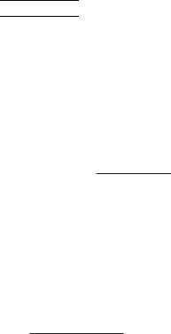
6.A 1/8" N.P.T. plugged tapping, accessible for test gauge connection, must be installed immediately upstream of the gas supply connection to the appliance.
7.Provide a drip leg in the gas piping near the gas unit heater. A ground joint union and a manual gas shutoff valve should be installed ahead of the unit heater controls to permit servicing. The manual shutoff valve must be located external to the jacket. (See Figure 4)
8.Make certain that all connections have been adequately doped and tightened.


 Do not over tighten the inlet gas piping into the valve. This may cause stresses that will crack the valve!
NOTICE: Use pipe joint sealant resistant to the action of liquefied petroleum gases regardless of gas conducted.


 Check all pipe joints for leakage using a soap solution or other approved method. Never use an open flame or severe personal injury or death may occur!
Figure 4 - Pipe Installation, Standard Controls


 Never use an open flame to detect gas leaks. Explosive conditions may exist which may result in personal injury or death!
The appliance and its individual shutoff valve must be disconnected from the gas supply piping system during any pressure testing of that system in excess of 1/2 psig (3.5 kPa).
The appliance must be isolated from the gas supply piping system by closing its individual manual shutoff valve during any pressure testing of the gas supply piping system at test pressures equal to or less than 1/2 psig (3.5 kPa).
Table 4 - Gas Piping Requirements
SINGLE STAGE GAS PIPING REQUIREMENTS*
GasType |
Natural Gas |
Propane (LP) Gas |
|
Manifold |
3.5 in. W.C. |
10.0 in. W.C. |
|
Pressure |
(0.9 kPa) |
(2.5 kPa) |
|
|
|
|
|
|
14.0 in. W.C. Max. |
14.0 in. W.C. Max. |
|
Supply Inlet |
(3.5 kPa) |
(3.5 kPa) |
|
Pressure |
|
|
|
5.0 in. W.C. Min. |
11.0 in W.C. Min. |
||
|
|||
|
(1.2 kPa) |
(2.7 kPa) |
*For single stage application only at normal altitudes.
8
ELECTRICAL CONNECTIONS
HAZARDOUS VOLTAGE!
DISCONNECT ALL ELECTRIC POWER INCLUDING REMOTE DISCONNECTS BEFORE SERVICING. Failure to disconnect power before servicing can cause severe personal injury or death.
Standard units are shipped for use on 115 volt, 60 hertz, single phase electric power. The motor name-plate and electrical rating of the transformer should be checked before energizing the unit heater electrical system. All external wiring must conform to the latest edition of ANSI/NFPA No. 70-2002, United States National Electrical Code, and applicable local codes; in Canada, to the Canadian Electrical Code, Part 1, CSA Standard C22.1.
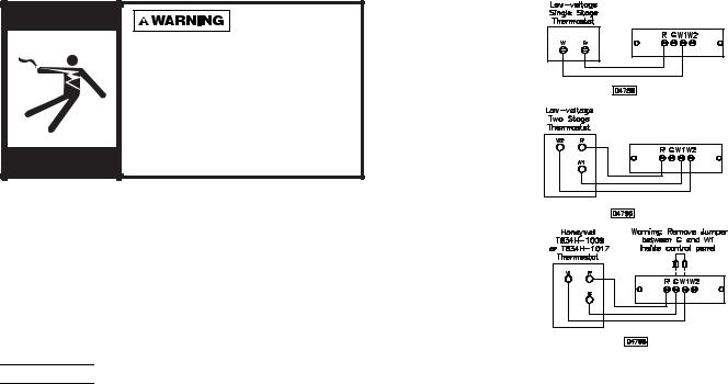
Figure 5a -
Low-voltage T
Thermostat Wiring
Single Stage
Figure 5b -
Low-voltage
Thermostat Wiring
Two Stage
Figure 5c - T834H-1009 or T834H-1017 Thermostat Wiring


 Do not use any tools (i.e. screwdriver, pliers, etc.) across terminals to check for power. Use a voltmeter.
It is recommended that the electrical power supply to each unit heater be provided by a separate, fused, and permanently live electrical circuit. A disconnect switch of suitable electrical rating should be located as close to the gas valve and controls as possible. Each unit heater must be electrically grounded in accordance with the latest edition of the United States National Electrical Code, ANSI/NFPA No. 70-2002, or CSA Standard C22.1. Refer to Figures 5a, 5b, 5c, 5d, 5e, 5f and 5g.
THERMOSTAT WIRING AND LOCATION:
THERMOSTAT HEAT ANTICIPATOR ADJUSTMENTS:
The initial heat anticipator setpoint should equal the thermostat's current amperage draw when the unit is firing. This setpoint should be measured for the best results. Use the recommended ranges for a guide. If further information is needed, consult your thermostat manufacturer's instructions.
Recommended heat anticipator setting ranges:
|
|
25 ft. (7.6m) |
50 ft. (15.2m) |
Gas Ignition Type |
T'stat Wiring |
T'stat Wiring |
|
|
|
|
|
For Tubular Units: |
0.85 to 0.90 |
0.90 to 1.1 A |
|
|
|
A |
Max. Setting |
|
|
|
on T'stat |
|
|
|
|
NOTICE: The thermostat must be mounted on a vertical, vibration-free surface, free from air currents, and in accordance with the furnished instructions.
Mount the thermostat approximately 5 feet (1.5m) above the floor, in an area where it will be exposed to a free circulation of average temperature air. Always refer to the thermostat instructions, as well as our unit wiring diagram, and wire accordingly. Avoid mounting the thermostat in the following locations:
1.Cold AreasOutside walls or areas where drafts may affect the operation of the control.
2.Hot AreasAreas where the sun's rays, radiation, or warm air currents may affect the operation of the control.
3.Dead AreasAreas where the air cannot circulate freely, such as behind doors or in corners.
FAN TIME DELAY CONTROL: Leads from the fan time delay control are factory wired to the junction box. The fan time delay control is a time delay relay (approximately 45 seconds ON, 65 seconds OFF). The fan time delay control is rated at 17 amps.
NOTICE: The start-up fan delay should not exceed 90 seconds from a cold start.
IMPORTANT: For all wiring connections, refer to the wiring diagram shipped with your unit (either affixed to the side jacket or enclosed in the installation instructions envelope). Should any original wire supplied with the heater have to be replaced, it must be replaced with wiring material having a temperature rating of at least 105° C.
Should any high limit wires have to be replaced, they must be replaced with wiring material having a temperature rating of 200° C minimum.
9
 Loading...