Beacon-Morris Twin-Flo III Installation Manual

TFII-11
Beacon/Morris TWIN-FLOIII® HEATER
INSTALLATION INSTRUCTIONS • TYPES K, W, & F
ATTENTION: READ THESE INSTRUCTIONS CAREFULLY BEFORE ATTEMPTING TO INSTALL, OPERATE, OR SERVICE THE BEACON MORRIS TWIN-FLO III HEATERS! RETAIN THESE INSTRUCTIONS FOR FUTURE REFERENCE.
INSPECT THE SHIPMENT IMMEDIATELY WHEN RECEIVED TO DETERMINE IF ANY DAMAGE HAS OCCURRED DURING SHIPMENT.
PRIOR TO INSTALLATION, CHECK FOR ANY VISIBLE DAMAGE. MAKE CERTAIN THAT ANY LOOSE PARTICLES ARE REMOVED (ESPECIALLY IN THE BLOWER ASSEMBLY AREA).
GENERAL DESCRIPTION
TWIN-FLO III heaters are for use with forced hot water residential heating systems and consist of a copper tube, aluminum finned heating element, with an electric motor and blower of unique cross flow design. Their purpose is to deliver a comfortable stream of warmed air, at or near floor level, and their construction is extremely compact so minimum space is required for installation. The type K heater is primarily used in horizonal floor installation, for example: under a kitchen counter cabinet, or bathroom sink enclosure. Type W is for verticle mounting, fully recessed in the wall studs, with the air discharged upward through a flush mounted, louvered front panel. Type F is a surface mounted wall unit, with the air discharged evenly through a louvered front panel in an upward direction. All types have heating elements with 1/2" nominal (5/8 O.D.) copper tube connections, and 115V. electric blower motor, interwired with a 120° F (49° C) reverse acting aquastat that prevents operation until hot water is circulating. These units are NOT intended to be used on one or two pipe steam systems. See bottom of page 7. For gravity fed systems, it is recommended that a separate circulator pump be installed for the kick space heater.
INSTALLING TWIN-FLO III TYPE K
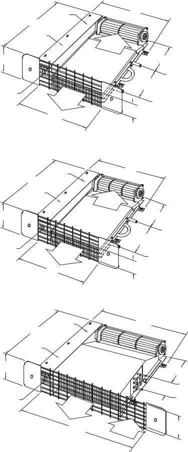
1.Select a location under the bottom shelf of a cabinet that meets the minimum dimensions shown in Fig. A.
2.CUT AN ACCESS PANEL THROUGH THE BOTTOM OF THE CABINET AT THIS LOCATION, LARGE ENOUGH FOR INSTALLATION AND SERVICE. IT IS RECOMMENDED THAT THIS ACCESS PANEL BE CONSTRUCTED SO ANNUAL CLEANING OF THE BLOWER FAN AND COIL FINS CAN BE EASILY ACCESSIBLE.
3.At this location, center and cut an opening in the toe-space riser 4'' high x 11'' long (model K42) (See figure A) or 4'' high x 18'' long (model K84) (See figure B) or 4" high x 23" long (Model K120). (See figure C).
4.Set the TWIN-FLO III in the space at finished floor level and check piping and wiring locations. The air outlet should be facing but not extending beyond the toe-space riser at the opening. The air outlet should also be located at the bottom portion of the 4'' toe-space riser (See figure A) at finished floor level. Make sure the switch is accessible through the grille openings. The front of the unit should fit flush to the inside of the toe space riser.
5.Install the wire grille over the 4'' toe-space opening by clamping in place with two end caps and screws provided. The verticle bars should be on the inside (fig. A).
6.If using the TWIN-FLO "Easy Connect" Flexible Hose Connection Kit, see those installation instructions.
7.Next, prepare the heating element for pipe connections (this procedure will also pertain to Model types W and F). Remove the 3 screws from the electric conn. box. Unsnap (pull) the thermostat clamp from the return copper U-bend. Holding down the top cover, remove the 4 element cover screws. Carefully remove this top cover noting the position of the element and the neoprene side pad. Lift out the element for soldering and fittings. Both ends are sized to accept 1/2'' solder fittings. (Note required fittings for one pipe and two pipe systems on page 6).
8.Replace the heating element in the bottom cover in the proper position. Place the neoprene side pad in position and replace the top cover using the 4 screws. Tighten enough to keep the element in place between the covers. DO NOT OVER-TIGHTEN!
9.Place the TWIN-FLO III under the cabinet and connect the piping and wiring. Make sure unit & outlet are free of any dirt or debris prior to start up. Turn on the system, purge of air, check blower operation and check for any possible leaks in the piping (run for 2 hrs. minimum). It should then be screwed to the floor through the four resilient mounting feet (2-inside electrical box and 2 external). Do not over-tighten screws. Secure top of electrical box.
Beacon/Morris
260 NORTH ELM STREET, WESTFIELD, MASSACHUSETTS 01085
7555 TRANMERE DRIVE, MISSISSAUGA, ONTARIO L5S 1L4 CANADA www.beacon-morris.com

TWIN-FLO III
TYPE K42
|
ELECTRIC |
FIGURE A |
CONNECTION |
BOX |
|
|
12 3/4 |
|
(324) |
|
AQUASTAT |
|
3 7/8 |
|
(98) |
SWITCH
|
HEATED |
|
DISCHARGE |
|
AIR |
|
11" (279) K42 |
TWIN-FLO III |
|
TYPE K84 |
|
FIGURE B |
ELECTRIC |
|
CONNECTION |
12 3/4 |
BOX |
(324) |
|
AQUASTAT |
|
3 7/8 |
|
(98) |
|
MAX |
|
OFF |
|
|
MIN |
SWITCH |
HEATED |
|
|
|
DISCHARGE |
|
AIR |
|
18" |
|
(457) |
TWIN-FLO III |
|
TYPE K120 |
|
FIGURE C |
ELECTRIC |
CONNECTION |
|
12 3/4 |
BOX |
(324) |
|
AQUASTAT
3 7/8
(98)
SWITCH
HEATED
DISCHARGE
AIR
23"
(584)
Dimensions shown
in English and metric ( ).
12 1/4
(311)
RETURN
AIR
6 1/4 MIN.
(159)
SUPPLY
6" PIPE
CENTERS (152)
RETURN
2" AIR
DISCHARGE (51)
CAT-55110C
19 1/4
(489)
RETURN
AIR
6 1/4 MIN.
(159)
SUPPLY
6" PIPE
CENTERS (152)
RETURN
2" AIR
DISCHARGE (51)
CAT-55111C
19 1/4
(489)
|
8 1/4 MIN. |
||
|
(210) |
||
|
2" PIPE |
SUPPLY |
|
|
|
||
|
CENTERS |
||
|
(51) |
RETURN |
|
|
|
||
RETURN |
3 1/2 AIR |
||
DISCHARGE |
|||
AIR |
|||
|
(89) |
||
|
|
||
CAT-55112B
2.

25"
(635)
INSTALLATION OF TWIN-FLO III WALL MODELS - TYPE “W” AND TYPE “F”
Figures D and F show exploded views of the wall models”W” & “F” Twin-Flo III's. Figure E shows the “W” type mounted in a wall with an air outlet at the top of the unit. Figure G shows the “F” type mounted. The louvers of the front panel will direct the air flow as shown. Use the following procedures for installation:
Type W Installation
|
|
|
14" (356) W42 |
|
|
|
|
|
|
|
|
|
21" (533) W84 |
W42 |
14 1/4 (362) |
|
|
|
|
|
|
|
21" (533) W120 |
|
4" (102) |
|
|||
|
|
|
W84 |
21 1/4 (540) |
|
|
|||
|
|
|
|
|
|
||||
|
|
|
|
W120 21 1/4 (540) |
|
MIN. |
|
||
|
3 |
|
|
|
|
|
|
|
|
|
5 |
|
|
|
|
|
|
|
|
1W |
6 |
|
|
|
|
|
|
|
|
|
|
|
|
|
|
SWITCH |
|
||
|
|
|
|
|
|
|
|
||
|
|
|
|
22 3/32 |
|
|
|
|
|
|
|
|
|
(561) |
|
|
|
25" |
|
|
|
|
|
|
|
|
FLOWAIR |
22 1/8 |
|
|
|
|
|
|
|
|
(635) |
||
|
|
|
|
|
|
|
|
(562) |
|
|
|
|
|
|
|
|
|
|
|
|
|
|
7 |
2W |
|
|
|
|
|
|
|
|
|
|
|
|
|
|
|
|
|
|
4" |
|
|
|
|
|
|
|
|
|
(102) |
|
|
|
|
|
|
|
|
|
|
RETURN |
|
|
ELECTRICAL |
|
|
|
|
9 |
|
W42 16" (406) |
KNOCKOUT |
CAT-55542A |
|||
|
4W 8 |
CAT-55524A |
W84 |
23" (584) |
|
|
|||
|
|
|
|
|
|||||
|
|
W120 23" (584) |
|
|
|
||||
16" (406) W42 |
1/2 |
|
|
SUPPLY |
|
|
|
|
|
23" (584) W84 |
|
|
|
|
|
|
|
|
|
(13) |
|
FIGURE D |
|
|
FIGURE E |
|
|
|
|
23" (584) W120 |
|
|
|
|
|
|
|||
|
|
|
|
|
|
|
|||
TYPE W |
1W. |
FRONT PANEL ASS'Y |
6. |
FLANGED NUTS |
|
FIGURE D |
2W. |
BACK RECESSED PANEL ASS'Y |
7. |
KICKSPACE ELECTRICAL CONTROL |
|
PARTS LIST |
3. |
KICKSPACE UNIT |
|
BOX COVER |
|
4W. |
FRONT PANEL MTG. SCREWS |
8. |
WASHERS (PLASTIC) |
||
|
|||||
|
5. |
LOCKWASHERS |
9. |
SNAP-CAP (PLASTIC) |
PART #3 (KICKSPACE UNIT) WILL BE SHIPPED IN IT'S OWN CARTON. ALL REMAINING PARTS ARE INCLUDED IN A SEPERATE CARTON.
TYPE “W” :
1.) Frame an opening between wall studding as shown in Figure E. Model W42 will fit between studs that are on 16'' centers. Model 5/B W84 and K120 will require a small amount of framing to suit the mounting. A 7/8'' diameter hole is provided at the bottom of the cabinet interior to provide entrances for electrical connections, and a 7/8'' diameter knockout is provided at the rear of the motor in the electrical control box. A 2-1/2'' diameter hole is provided at the bottom of the cabinet interior to provide an entrance for piping connections. Cut horizonal framing to clear, as necessary.
2.) After removing the front panel mounting screws (Item 4W), remove the front louvered panel (Item 1W). Notice the direction of the louvers (see the air flow direction label on inside front label).
3.) Nail the recessed cabinet (Item 2W) to the framed opening at both sides.
4.) Mount the Kickspace Unit (Item 3) to the recessed back panel, remove the electrical control box cover from kickspace unit. Secure the kickspace unit in place using Items 5 & 6 as shown in Figure D. Do not over tighten.
5.) Remove the heating element from the kickspace unit (Item 3) following the procedure described in the installation of Type “K”, step 6. Hold this element and fittings temporarily in place in the recessed cabinet before soldering to check for clearance and length of tubing required.
6.) After piping connections have been made, return the element to the cabinet as described in Type K installation, step 8.
7.) Electrical connections for the wall units are to be made as shown on page 5.
8.) Make final piping and electrical connections (see pages 5 & 6) to the system in the cabinet. Secure in place the kickspace electrical control box cover. Turn on the system, purge of air, check blower operation, and check for any possible leaks in the piping.
9.) Replace front panel (Item 1W), place washers (Items 8) in required positions, screw through holes and tighten.
10.) Place snap-cap® (Item 9) over washer at angle. Push snap-cap® (Item 9) DOWN firmly until it engages with a snap.
3.
 Loading...