

Page 1

03.19· 174.02.073/4
Subject to modification in technic and design.
www.baumer.com Errors and omissions excepted.
Manual
Inclination sensor GIM500R with CANopen® interface
Firmware version 1.00 and up
Page 2

Baumer_GIM500R_CANopen_MA_EN.docx 2/29 www.baumer.com
03.19
Contents Page
1 Introduction ................................................................................................................................................. 3
1.1 Scope of delivery ....................................................................................................................................... 3
1.2 Product assignment ................................................................................................................................... 3
2 Safety and operating instructions ............................................................................................................ 4
3 CAN-bus and CANopen communication .................................................................................................. 5
3.1 CAN-bus characteristics ............................................................................................................................ 5
3.2 CANopen ................................................................................................................................................... 6
3.3 CANopen communication .......................................................................................................................... 6
3.3.1 Communication profile ............................................................................................................................ 6
3.3.2 CANopen message structure ................................................................................................................. 7
3.3.3 Service data communication .................................................................................................................. 8
3.3.4 Process data communication ............................................................................................................... 10
3.3.5 Emergency service ............................................................................................................................... 11
3.3.6 Network management services ............................................................................................................ 14
3.4 Object Dictionary ..................................................................................................................................... 21
3.4.1 Communication Parameter (CiA DS-301, CiA DS-302 Part 2) ............................................................. 22
3.4.2 Manufacturer Specific Parameter ......................................................................................................... 23
3.4.3 Device Profile Specific Parameter (CiA DS-410) ................................................................................. 25
3.5 LED status display ................................................................................................................................... 28
3.5.1 CANopen Status LED (Green) ............................................................................................................. 28
3.5.2 CANopen Error LED (Red) ................................................................................................................... 28
4 Terminal assignment ................................................................................................................................ 29
4.1 M12 flange connector, 5-pin .................................................................................................................... 29
4.2 2xM12 flange connector, 5-pin ................................................................................................................ 29
4.3 Cable ....................................................................................................................................................... 29
Page 3
Baumer_GIM500R_CANopen_MA_EN.docx 3/29 www.baumer.com
03.19
Disclaimer of liability
The present manual was compiled with utmost care, errors and omissions reserved. For this reason
Baumer rejects any liability for the information compiled in the present manual.
Baumer nor the author will accept any liability for direct or indirect damages resulting from the use of the
present information.
At any time we should be pleased receiving your comments and proposals for further improvement of the
present manual.
Created by:
Baumer IVO GmbH & Co. KG
Villingen-Schwenningen, Germany
1 Introduction
1.1 Scope of delivery
Please check the delivery upon completeness prior to commissioning.
Depending on sensor configuration and part number delivery is including:
Sensor
Describing file and manual (also available as download in the Internet)
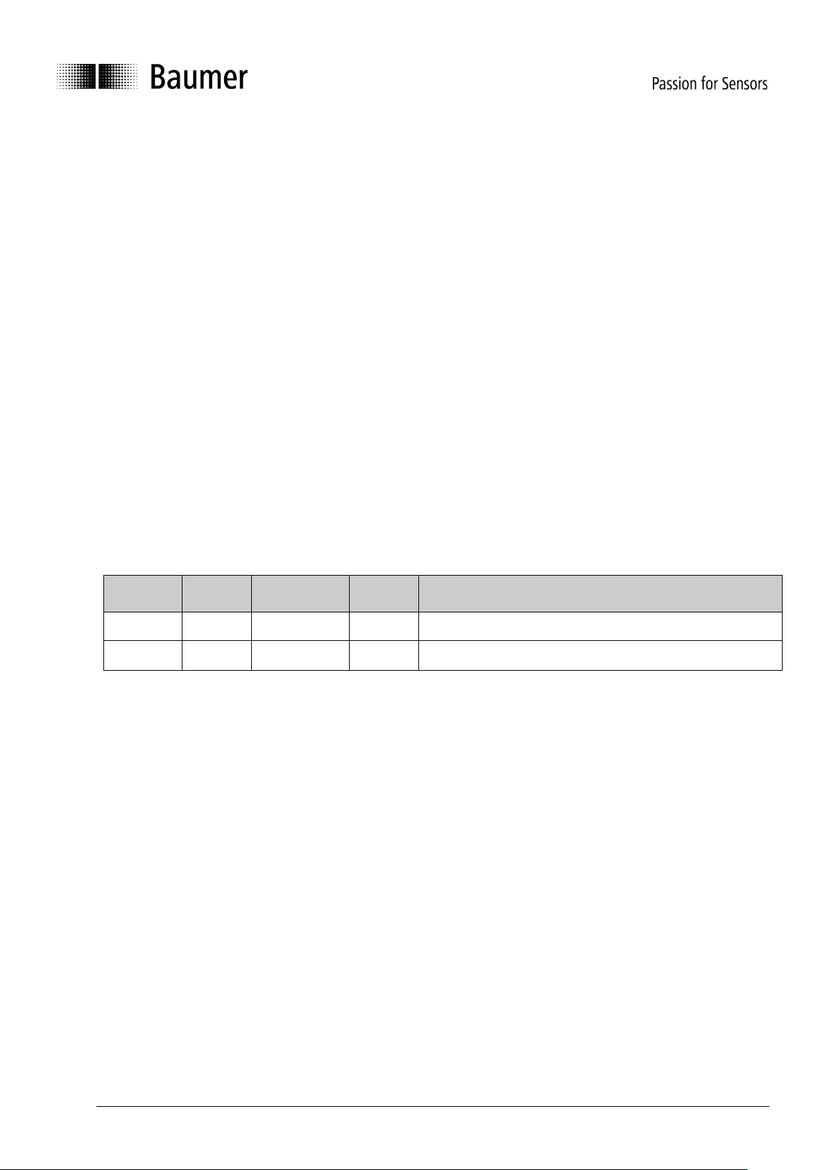
1.2 Product assignment
Product
Product
code
Measuring
direction
Device
name
EDS file
GIM500R
0x40
1-dimensional
GIM500
160502_GIM500R_V1_00_PDO_SPEC_1_1dimensional
GIM500R
0x40
2-dimensional
GIM500
160502_GIM500R_V1_00_PDO_SPEC_1_2dimensional
Page 4

Baumer_GIM500R_CANopen_MA_EN.docx 4/29 www.baumer.com
03.19
2 Safety and operating instructions
Intended use
The inclination sensor is a precision measuring device to determine angular positions and to supply the
downstream device with measured values in the form of electronic output signals. The inclination sensor
must not be used for any other purpose.
Make sure the appropriate safety measures are present to prevent damage to persons, the system or
operating facilities in case of sensor error or failure.
Personnel qualification
The inclination sensor must only be installed by a qualified electronics and precision mechanics.
Observe the user manual of the machine manufacturer.
Maintenance
The inclination sensor is maintenance-free and must not be opened or modified in its electronics or
mechanical design. Opening the sensor can lead to personal injury.
Disposal
The inclination sensor contains electronic components. At its disposal, local environmental guidelines
must be followed.
Installation
Avoid mechanical impacts or shocks on the housing.
Electrical commissioning
Do not perform any electrical modifications at the inclination sensor.
Do not carry out any wiring work when the inclination sensor is live.
Do not dock or undock the electrical connection while the inclination sensor is live.
Ensure that the entire equipment is installed in line with EMC requirements. Ambient conditions and
wiring affect the electromagnetic compatibility of the inclination sensor. Install sensor and supply cables
separately or far away from lines with high interference emissions (frequency converters, contactors,
etc.).
Provide separate power supply for the inclination sensor where working with consumers that have high
interference emissions.
Completely shield the inclination sensor housing and connecting cables.
Connect the sensor to protective earth (PE) using shielded cables. The braided shield must be
connected to the cable gland or connector. Ideally, aim at a bilateral connection to protective earth (PE),
the housing via the mechanical assembly and the cable shield via the downstream devices. In case of
earth loop problems, earth on one side only as a minimum requirement.
Supplementary information
This manual is intended as a supplement to already existing documentation (i.e. catalogue, product
information and mounting instruction).
Page 5

Baumer_GIM500R_CANopen_MA_EN.docx 5/29 www.baumer.com
03.19
3 CAN-bus and CANopen communication
CAN bus (CAN: Controller Area Network) was developed by Bosch and Intel for high-speed, economic data
transmission in automotive applications. Today CAN bus has been commercialized for use in industrial
automation.
CAN bus is a fieldbus system (standards administered by CAN in Automation, CiA) for communication
between appliances, actors and sensors of different brands.
3.1 CAN-bus characteristics
• Data rate of 1 MBaud with network expansion up to 40 m
• Network connected on both sides
• The bus medium is a twisted-pair cable
• Real time capability: Defined maximum waiting time for high-priority messages.
• Theoretically 127 users at one bus, but physically only 32 are possible (due to the driver).
• Ensures data consistency across the network. Damaged messages are notified as faulty for all network
nodes.
• Message-oriented communication
The message is identified by a message identifier. All network nodes use the identifier to test whether the
message is of relevance for them.
• Broadcasting, multicasting
All network nodes receive each message simultaneously. Synchronization is therefore possible.
• Multimaster capability
Each user in the field bus is able to independently transmit and receive data without being dependent upon
the priority of the master. Each user is able to start its message when the bus is not occupied. When
messages are sent simultaneously, the user with the highest priority prevails.
• Prioritization of messages
The identifier defines the priority of the message. This ensures that important messages are transmitted
quickly via the bus.
• Residual error probability
Safety procedures in the network reduce the probability of an undiscovered faulty data transmission to
below 10
-11
. In practical terms, it is possible to ensure a 100% reliable transmission.
• Function monitoring
Localization of faulty or failed stations. The CAN protocol encompasses a network node monitoring
function. The function of network nodes which are faulty is restricted, or they are completely uncoupled
from the network.
• Data transmission with short error recovery time
By using several error detection mechanisms, falsified messages are detected to a high degree of
probability. If an error is detected, the message transmission is automatically repeated.
In the CAN Bus, several network users are connected by means of a bus cable. Each network user is able to
transmit and receive messages. The data between network users is serially transmitted.
Examples of network users for CAN bus devices are:
• Automation devices such as PLCs
• PCs
• Input and output modules
• Drive control systems
• Analysis devices, such as a CAN monitor
• Control and input devices as Human Machine Interfaces (HMI)
• Sensors and actuators
Page 6

Baumer_GIM500R_CANopen_MA_EN.docx 6/29 www.baumer.com
03.19
3.2 CANopen
Under the technical management of the Steinbeis Transfer Centre for Automation, the CANopen profile was
developed on the basis of the Layer 7 specification CAL (CAN Application Layer). In comparison with CAL,
CANopen only contains the functions suitable for this application. CANopen thus represents only a partial
function of CAL optimized for the application in hand, so permitting a simplified system structure and the use
of simplified devices. CANopen is optimized for fast data exchange in real time systems.
The organization CAN in Automation (CiA) is responsible for the applicable standards of the relevant profiles.
CANopen permits:
• Simplified access to all device and communication parameters
• Synchronization of several devices
• Automatic configuration of the network
• Cyclical and event-controlled process data communication
CANopen comprises four communication objects (COB) with different characteristics:
• Process data objects for real time data (PDO)
• Service data objects for parameter and program transmission (SDO)
• Network management (NMT, Heartbeat)
• Pre-defined objects (for synchronization, emergency message)
All device and communication parameters are subdivided into an object directory. An object directory
encompasses the name of the object, data type, number of subindexes, structure of the parameters and the
address. According to CiA, this object directory is subdivided into three different parts. Communication
profile, device profile and a manufacturer-specific profile (see object directory).
3.3 CANopen communication
3.3.1 Communication profile
Communication between the network users and the Master (PC / Control) takes place by means of object
directories and objects. The objects are addressed via a 16 bit index. The CANopen communication profile
DS 301 standardizes the various communication objects. They are accordingly divided into several groups:
• Process data objects PDO for real time transmission of process data
• Service data objects SDO for read/write access to the object directory
• Objects for synchronization and error display of CAN users:
- SYNC object (synchronization object) for synchronization of network users
- EMCY object (emergency object) for error display of a device or its peripherals
• Network management NMT for initialization and network control
• Layer Setting Services LSS for configuration by means of serial numbers, revision numbers etc. in the
middle of an existing network
Page 7
Baumer_GIM500R_CANopen_MA_EN.docx 7/29 www.baumer.com
03.19
3.3.2 CANopen message structure
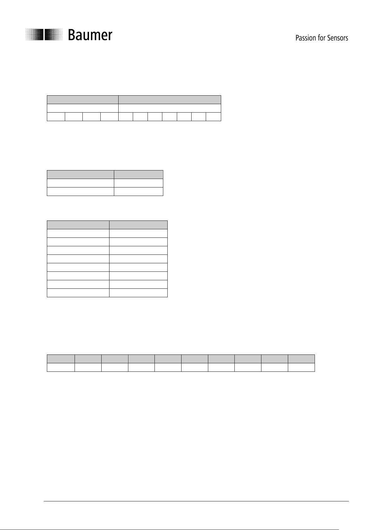
The first part of a message is the COB ID (Identifier).
Structure of the 11-bit COB ID:
Function code
Node ID
4-bit function code
7-bit node ID
The function code provides information on the type of message and priority
The lower the COB ID, the higher the priority of the message
Broadcast messages:
Function code
COB ID
NMT
0
SYNC
80h
Peer to peer messages:
Function code
COB ID
Emergency
80h + Node ID
PDO1 (tx)
1)
180h + Node ID
PDO2 (tx)
1)
280h + Node ID
SDO (tx)
1)
580h + Node ID
SDO (rx)
1)
600h + Node ID
Heartbeat
700h + Node ID
LSS (tx)
1)
7E4h
LSS (rx)
1)
7E5h
1): (tx) and (rx) from the viewpoint of the sensor
The node ID can be freely selected by means of the CANopen bus between 1 and 127.
The sensors are supplied with the Node ID 1 and baud rate 50 kBit/s.
This can be changed with the service data object 2101h or object 2100h or using LSS.
A CAN telegram is made up of the COB ID and up to 8 bytes of data:
COB ID
DLC
Byte 1
Byte 2
Byte 3
Byte 4
Byte 5
Byte 6
Byte 7
Byte 8
Xxx x xx
xx
xx
xx
xx
xx
xx
xx
The precise telegram is outlined in more detail at a later point.
Page 8
Baumer_GIM500R_CANopen_MA_EN.docx 8/29 www.baumer.com
03.19
3.3.3 Service data communication
The service data objects correspond to the standards of the CiA. It is possible to access an object via index
and subindex. The data can be requested or where applicable written into the object.
General information on the SDO
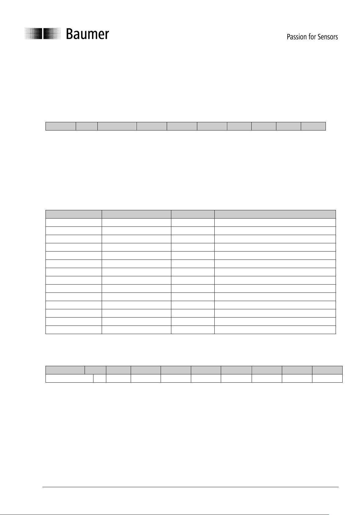
Structure of an SDO telegram:
COB ID
DLC
Command
Object L
Object H
Subindex
Data 0
Data 1
Data 2
Data 3
An SDO-COB ID is composed as follows:
Master -> Sensor : 600h + Node ID
Sensor -> Master : 580h + Node ID
DLC (data length code) describes the length of the telegram. This is composed as follows:
1 byte command + 2 bytes object + 1 byte subindex + no. of data bytes (0 - 4).
The command byte defines whether data is read or set, and how many data bytes are involved.
SDO command
Description
Data length
22h
Download request
Max. 4 Byte
Transmits parameter to sensor
23h
Download request
4 byte
2Bh
Download request
2 byte
2Fh
Download request
1 byte
60h
Download response
-
Confirms receipt to master
40h
Upload request
-
Requests parameter from sensor
42h
Upload response
Max. 4 byte
Parameter to master with max. 4 byte
43h
Upload response
4 byte
4Bh
Upload response
2 byte
4Fh
Upload response
1 byte
80h
Abort message
-
Sensor signals error code to master
An abort message indicates an error in the CAN communication. The SDO command byte is 80h. The
object and subindex are those of the requested object. The error code is contained in bytes 5…8.
ID
DLC
Byte 1
Byte 2
Byte 3
Byte 4
Byte 5
Byte 6
Byte 7
Byte 8
580h + Node ID
8
80h
Object L
Object H
Subindex
ErrByte 0
ErrByte 1
ErrByte 2
ErrByte 3
Page 9
Baumer_GIM500R_CANopen_MA_EN.docx 9/29 www.baumer.com
03.19
Byte 8..5 results in the SDO abort message (byte 8 = MSB).
The following messages are supported:
05040001h : Command byte is not supported
06010000h : Incorrect access to an object
06010001h : Read access to write only
06010002h : Write access to read only
06020000h : Object is not supported
06090011h : Subindex is not supported
06090030h : Value outside the limit
06090031h : Value too great
08000000h : General error
08000020h : Incorrect save signature
08000021h : Data cannot be stored
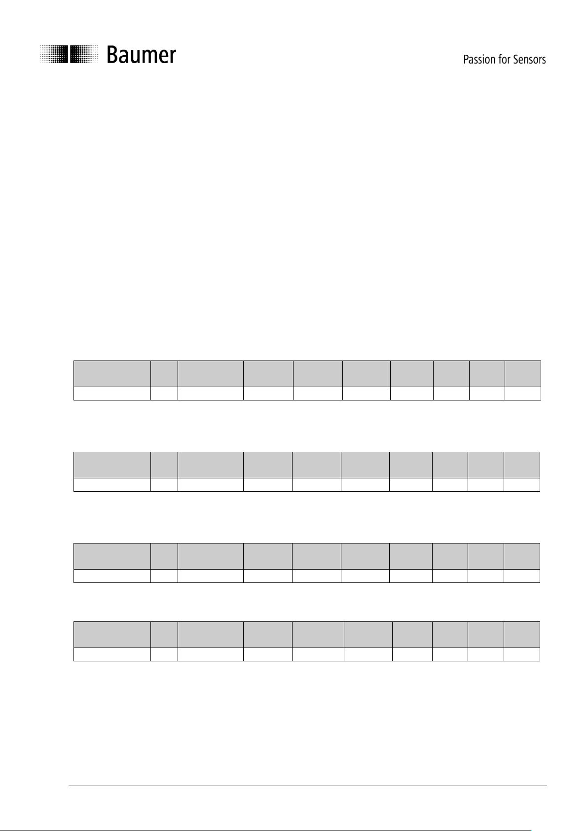
SDO examples
Request of the resolution value by the master from the slave
A frequent request will be a request for the resolution. Object 6000h
COB ID
DLC
Command
Object L
Object H
Subindex
Data 0
Data
1
Data
2
Data
3
600h+node ID
8
40h
00h
60h 0 x x x
x
Response by the slave to the request for a value
The resolution is 2 bytes long, the precise values can be found under object 6000h.
COB ID
DLC
Command
Object L
Object H
Subindex
Data 0
Data
1
Data
2
Data
3
580h+node ID
8
4Bh
00h
60h 0 a b c
d
Writing of a value by the master into the slave
Inclination setting can be performed with preset for longitudinal slope. Object 6012h
COB ID
DLC
Command
Object L
Object H
Subindex
Data 0
Data
1
Data
2
Data
3
600h+node ID
8
2Bh
12h
60h 0 a b c
d
Slave's response to the writing of a value
COB ID
DLC
Command
Object L
Object H
Subindex
Data 0
Data
1
Data
2
Data
3
580h+node ID
8
60h
12h
60h 0 0 0 0
0
Page 10
Baumer_GIM500R_CANopen_MA_EN.docx 10/29 www.baumer.com
03.19
3.3.4 Process data communication
Process data objects are used for real time data exchange for process data, for example inclination or
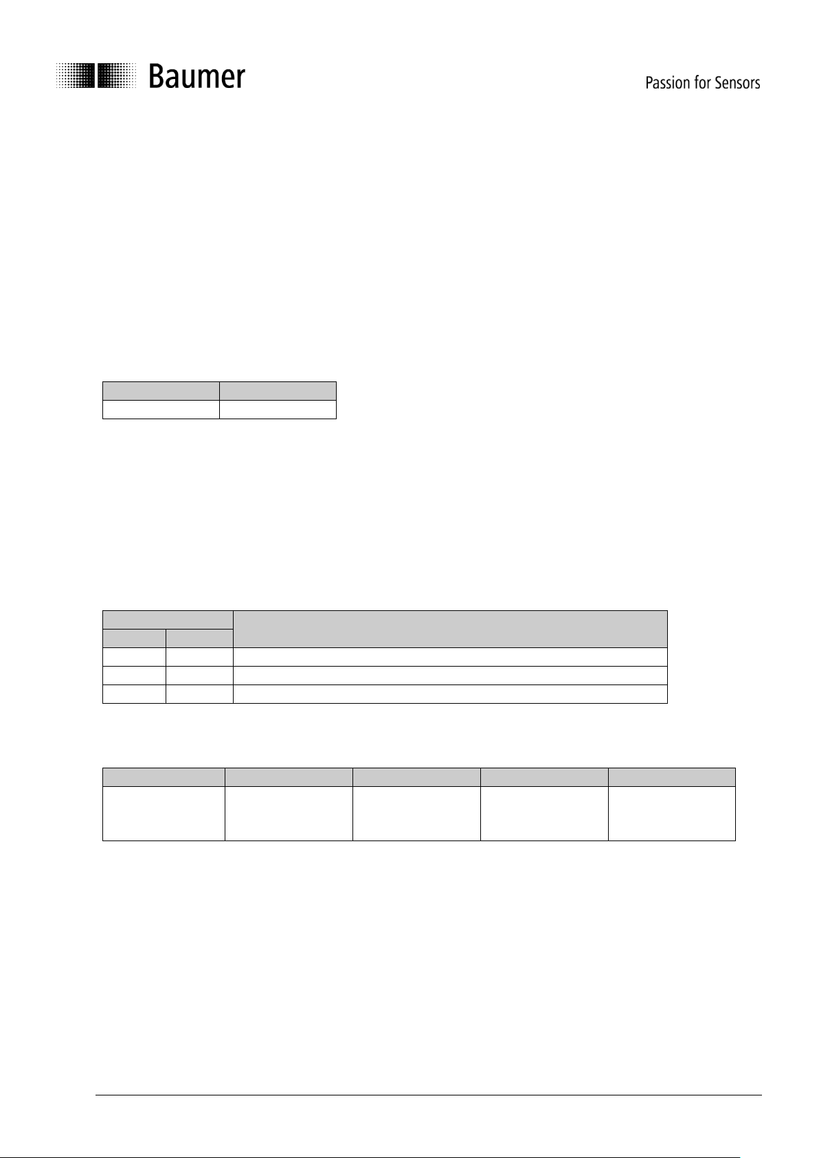
operating status. PDOs can be transmitted synchronously or cyclically (asynchronously).
Synchronous
In order to transmit the process data synchronously, a value between 1 and F0h (=240) must be written into
the object 1800h Subindex 2. If the value is 3, the PDO is transmitted on every third sync telegram (if the
value 1 is entered, transmission takes place on every sync telegram). The counter for the number of PDOs
to be transmitted is reset in the event of a position change or NMT reset, i.e. unless it is changed, the
position is transmitted five times. If the position changes, it is transmitted a further five times.
In synchronous operation, the PDO is requested by the master via the Sync telegram.
Byte 0
Byte 1
COB ID = 80
0
Cyclical (asynchronous)
If you wish the PDOs to be transmitted cyclically, the value FEh must be written into the object 1800h /
1801h Subindex 2. In addition, the cycle time in milliseconds must be entered in the same object subindex 5.
The entered time is rounded off to 1 ms. If the value is stored for 0 ms, the PDOs are not transmitted. The
function is switched off.
Overview
In the following table, the different transmission modes for PDOs are summarized:
1800h
Summarized description
Sub2
Sub5
FEh/FFh
3ms
Cyclical transmission every 3 ms
FEh/FFh
0ms
Transmit PDO switched off
3
xxx
Transmit with every third sync telegram
Object 1A00h subindex 0-3 defines the PDO - mapping. The format is shown in the following table:
ID
DLC
Byte 1+2
Byte 3+4
Byte 5+6
181h
6
6511h
(Temperature)
6010h
(horizontal /
long Value / X)
6020h
(vertical /
lateral Value / Y)
Page 11
Baumer_GIM500R_CANopen_MA_EN.docx 11/29 www.baumer.com
03.19
3.3.5 Emergency service
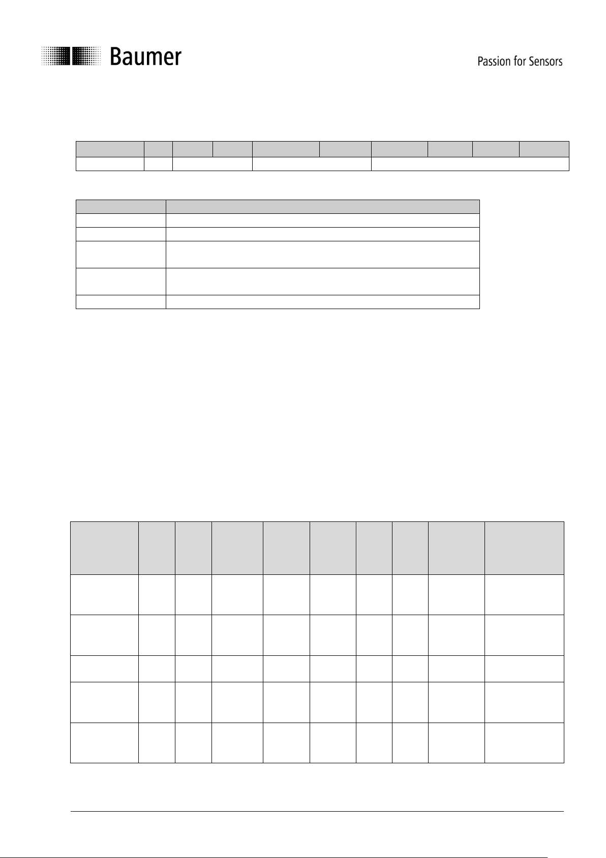
Internal device error or bus problems initiate an emergency message:
COB-ID
DLC
Byte0
Byte 1
Byte 2
Byte 3
Byte 4
Byte 5
Byte 6
Byte 7
80h+Node-ID
8
Error Code
Error ID
Manufacturer Specific
Byte 0+1: Error Codes
Error Code (hex)
Meaning
0000
Error Reset or No Error
1000
Generic Error
4200
Device Temperature
(Internal temperature above working temperature)
5010
Physical Measurement Error
(Sensor is out of measuring range)
FF01
Internal Sensor Error
The GIM500 inclination sensor features varied diagnostic options.
In the event of error affecting device operation, an emergency message is once transmitted by Error ID.
The error should be considered as active, until the sensor is sending 0000h Error code for the corresponding
Error ID.
The LED is red continuous as long as the error is present. For the time of error presence, the inclination
value should be considered invalid. Should the error prevail and remain active, please contact Baumer
support.
Diagnosis active errors
CANopen
The LED status indicator lights up red.
If the error is active, an error message is sent.
CANopen EMCY-Message Frame Structure:
COB-ID
[hex]
Error
Code
LSB
[hex]
Error
Code
MSB
[hex]
Error
Register
[hex]
Error
Module
LSB
[hex]
Error
Module
MSB
[hex]
Error
ID
MSB
[hex]
Error
ID
LSB
[hex]
Reserved
[hex]
Description
0x80+Node-
ID
00
10
00
See
error
list
See
error
list
See
error
list
See
error
list
00
“Generic error”
was set
0x80+Node-
ID
00
00
00
See
error
list
See
error
list
00
00
00
“Generic error”
was reset
0x80+Node-
ID
00
42
00
00
10
10
00
00
“Temperature
error” was set
0x80+Node-
ID
00
00
00
00
10
00
00
00
“Temperature
error” was
reset
0x80+Node-
ID
01
FF
00
00
22
10
01
00
„Longitudinal
sensor defect“
was set
Page 12

Baumer_GIM500R_CANopen_MA_EN.docx 12/29 www.baumer.com
03.19
0x80+Node-
ID
00
00
00
00
22
00
00
00
„Longitudinal
sensor defect“
was reset
0x80+Node-
ID
10
50
00
00
06
10
00
00
“Longitudinal
value out of
range” was set
0x80+Node-
ID
00
00
00
00
06
00
00
00
“Longitudinal
value out of
range” was
reset
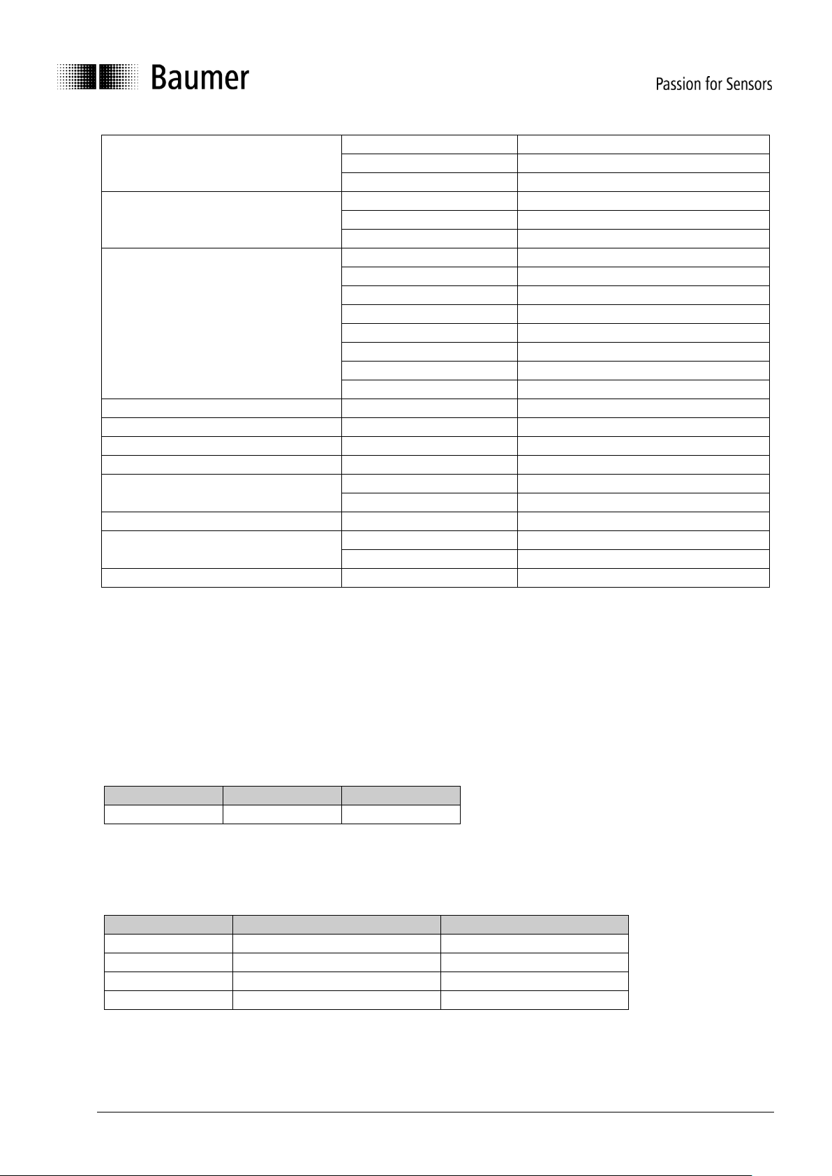
CANopen Error List
Error Module ID
Error ID
Error Description
0x0000
0x0005
index out of bound
0x0001
0x1001
scheduler initialization
0x0001
zero pointer
0x0002
0x0005
index out of bound
0x0003
0x0001
zero pointer
0x0005
index out of bound
0x0006
switch default case reached
0x0004
0x0006
switch default case reached
0x0005
0x0004
checksum
0x0006
0x000B
division by zero
0x1000
device flipped
0x0007
0x1001
overvoltage 5v operating
0x1002
overvoltage 5v max
0x1003
overvoltage 3.3v max
0x1004
overvoltage 3.3v operating
0x0008
0x0001
zero pointer
0x0009
0x1000
stack overflow
0x000A
0x1000
RAM test wrong area
0x1001
RAM error
0x0006
switch default case reached
0x000B
0x0001
zero pointer
0x0006
switch default case reached
0x1000
acc sensor configuration
0x1001
acc control register
0x1002
FIFO overflow
0x1003
wrong full scale range
0x000C
0x0001
zero pointer
0x000D
0x1001
IWDG restart
0x000E
0x0005
index out of bound
0x0009
time out
0x1000
I2C clock speed
0x1003
I2C data length
0x1004
I2C GPIO Stuck
0x000F
0x0005
index out of bound
0x0010
0x0005
index out of bound
Page 13

Baumer_GIM500R_CANopen_MA_EN.docx 13/29 www.baumer.com
03.19
0x1000
operating temperature beyond
specified area
0x0011
0x0005
index out of bound
0x0012
0x0001
zero pointer
0x0004
checksum
0x0005
Array Index error
0x000B
division by zero
0x0013
0x0005
index out of bound
0x0014
0x0005
index out of bound
0x0015
0x0005
index out of bound
0x0016
0x0001
zero pointer
0x1000
Wrong DAC channel
0x0017
0x0001
zero pointer
0x0006
switch default case reached
0x0009
time out
0x0018
0x0001
zero pointer
0x0019
0x0005
index out of bound
0x001A
0x0001
zero pointer
0x1000
FRAM volume
0x1001
FRAM write error
0x1002
FRAM reset status
0x001B
0x0001
zero pointer
0x1001
Wrong error module ID
0x1002
Not existing Error ID
0x001C
0x0001
zero pointer
0x1000
DAC output mode
0x1001
Channel number
0x1002
Channel initialization
0x1003
Gain zero
0x1004
Position beyond specified area
0x001D
0x0001
zero pointer
0x000B
division by zero
0x001E
0x0006
switch default case reached
0x1000
CPU operation error
0x1001
CPU operation error
0x1002
CPU operation error
0x1003
CPU operation error
0x1004
CPU operation error
0x1005
CPU operation error
0x1006
CPU operation error
0x1007
CPU operation error
0x1008
CPU operation error
0x1009
CPU operation error
0x100A
CPU operation error
0x100B
CPU operation error
0x100C
CPU operation error
0x100D
CPU operation error
0x001F
0x000A
Overflow
0x0020
0x0001
zero pointer
0x0006
switch default case reached
Page 14
Baumer_GIM500R_CANopen_MA_EN.docx 14/29 www.baumer.com
03.19
0x0021
0x0001
zero pointer
0x0005
index out of bound
0x0006
switch default case reached
0x0022
0x0005
index out of bound
0x1000
MEMS initialization
0x1001
Static acc data
0x0023
0x1000
Parameterization error
0x1001
Parameterization error
0x1002
Parameterization error
0x1003
Parameterization error
0x1004
Parameterization error
0x1005
Parameterization error
0x1006
Parameterization error
0x1007
Parameterization error
0x0024
0x0005
index out of bound
0x0025
0x0006
switch default case reached
0x0026
0x0006
switch default case reached
0x0027
0x0006
switch default case reached
0x0028
0x0006
switch default case reached
0x000A
Overflow
0x0029
0x0005
index out of bound
0x002A
0x0006
switch default case reached
0x000A
Overflow
0x002B
0x0006
switch default case reached
3.3.6 Network management services
Network management can be divided into two groups.
Using the NMT services for device monitoring, bus users can be initialized, started and stopped.
In addition, NMT services exist for connection monitoring.
Description of the NMT command
The commands are transmitted as unconfirmed objects and are structured as follows:
Byte 0
Byte 1
Byte 2
COB ID = 0
Command byte
Node number
The COB ID for NMT commands is always zero. The node ID is transmitted in byte 2 of the NMT command.
Command byte
Command byte
Description
In state event drawing
01h
Start remote node
1
02h
Stop remote node
2
80h
Enter pre-operational mode
3
81h, 82h
Reset remote node
4, 5
The node number corresponds to the node ID of the required users. With node number = 0, all users are
addressed.
Page 15
Baumer_GIM500R_CANopen_MA_EN.docx 15/29 www.baumer.com
03.19
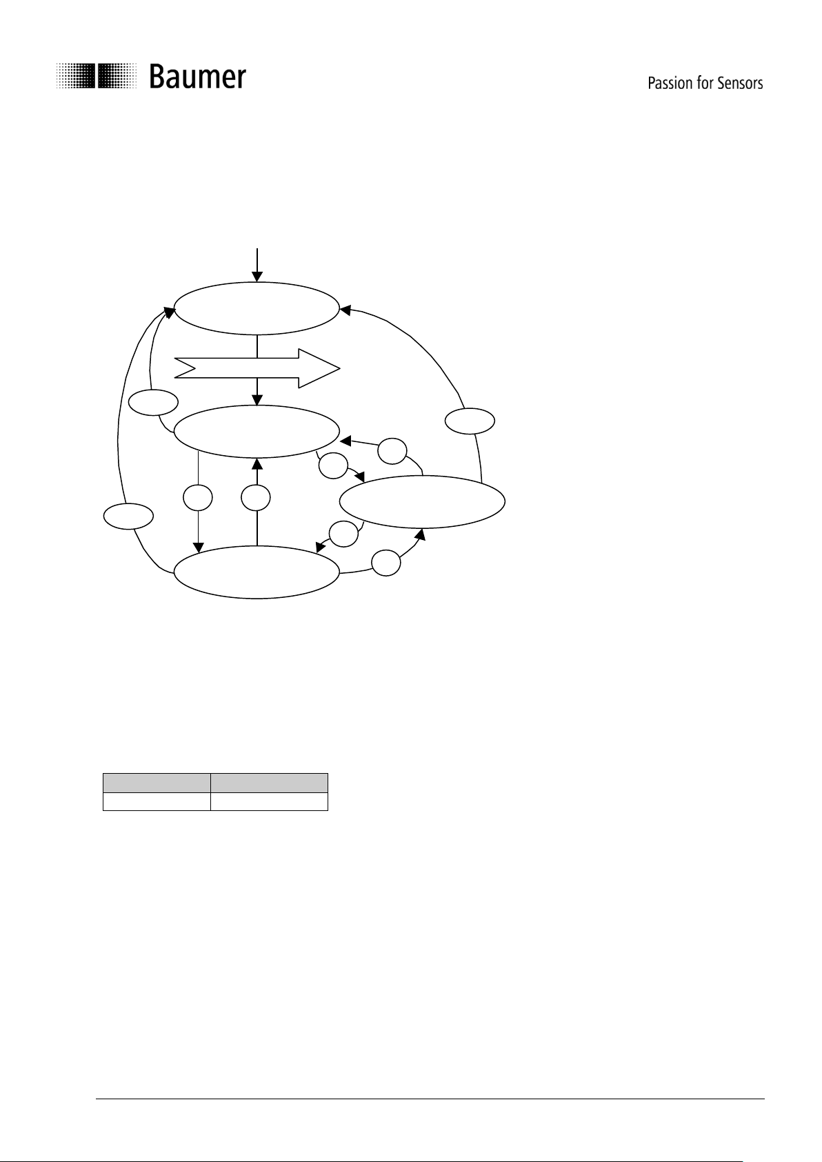
NMT state event
Following initialization, the encoder is in the pre-operational mode. In this status, SDO parameters can be
read and written. In order to request PDO parameters, the encoder must first be moved to the operational
mode status.
Power on or hardware reset
The various NMT statuses
Init
Following initialization, the encoder logs on to the CAN bus with a BootUp message. The encoder then goes
automatically to the pre-operational mode status.
The COB ID of the BootUp message is made up of 700h and the node ID.
COB ID
Byte 0
700h + node ID
00
Pre-operational mode
In the pre-operational mode, SDOs can be read and written.
Operational mode
In the operational mode, the encoder transmits the requested PDOs. In addition, SDOs can be read and
written.
Stopped or prepared mode
In the stopped mode, only NMT communication is possible. No SDO parameters can be read or set. LSS is
only possible in the stopped mode.
Init
Pre-Operational
Operational
Stopped/Prepared
Power on oder Hardware Reset
1
321
3
2
4/5
BootUp Message
4/5
4/5
Page 16
Baumer_GIM500R_CANopen_MA_EN.docx 16/29 www.baumer.com
03.19
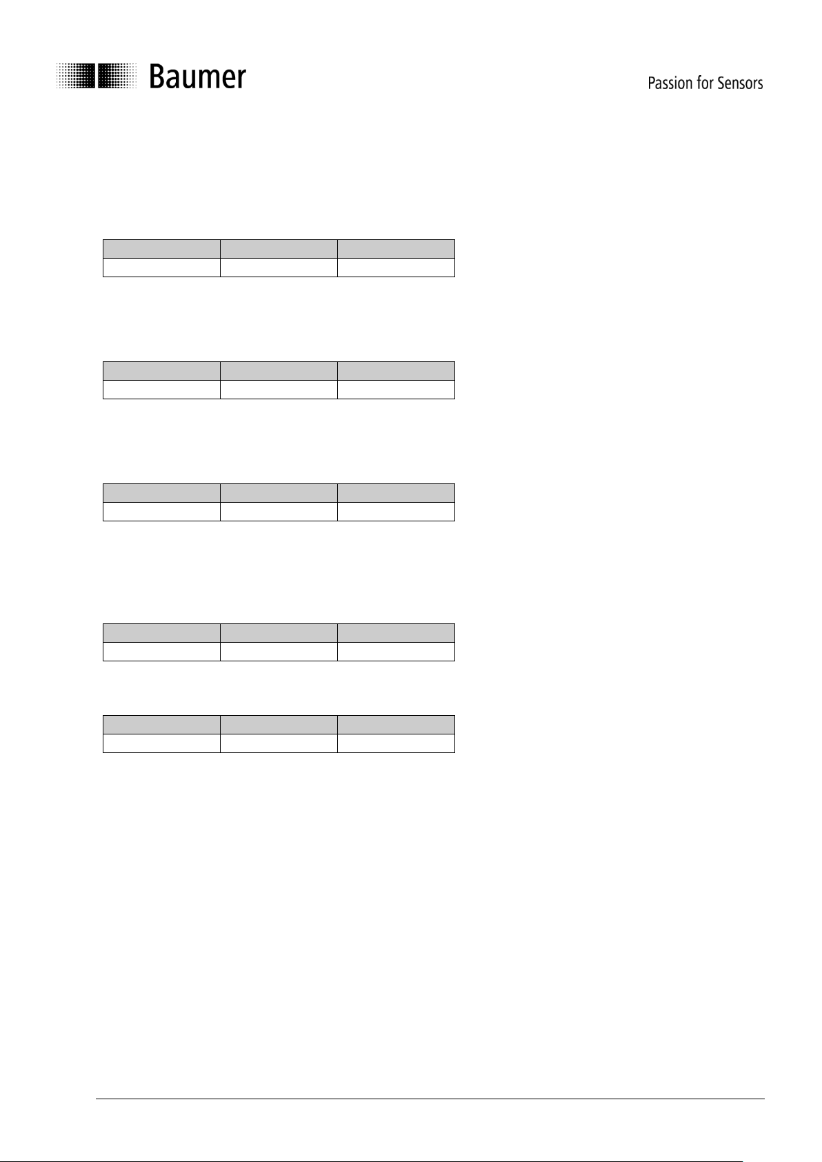
Status change
Start remote node (1)
With the start command, the encoder is switched to the operational mode status.
COB ID
Command byte
Node number
0
1h
0…127
Stop remote node (2)
With the stop command, the encoder is switched to the stopped or prepared mode status.
COB ID
Command byte
Node number
0
2h
0…127
Enter pre-operational mode (3)
Change to the pre-operational mode status.
COB ID
Command byte
Node number
0
80h
0…127
Reset remote node (4) or reset communication (5)
With the reset command, the sensor is re-initialized.
Reset remote node (4):
COB ID
Command byte
Node number
0
81h
0…127
Reset communication (5):
COB ID
Command byte
Node number
0
82h
0…127
Page 17
Baumer_GIM500R_CANopen_MA_EN.docx 17/29 www.baumer.com
03.19
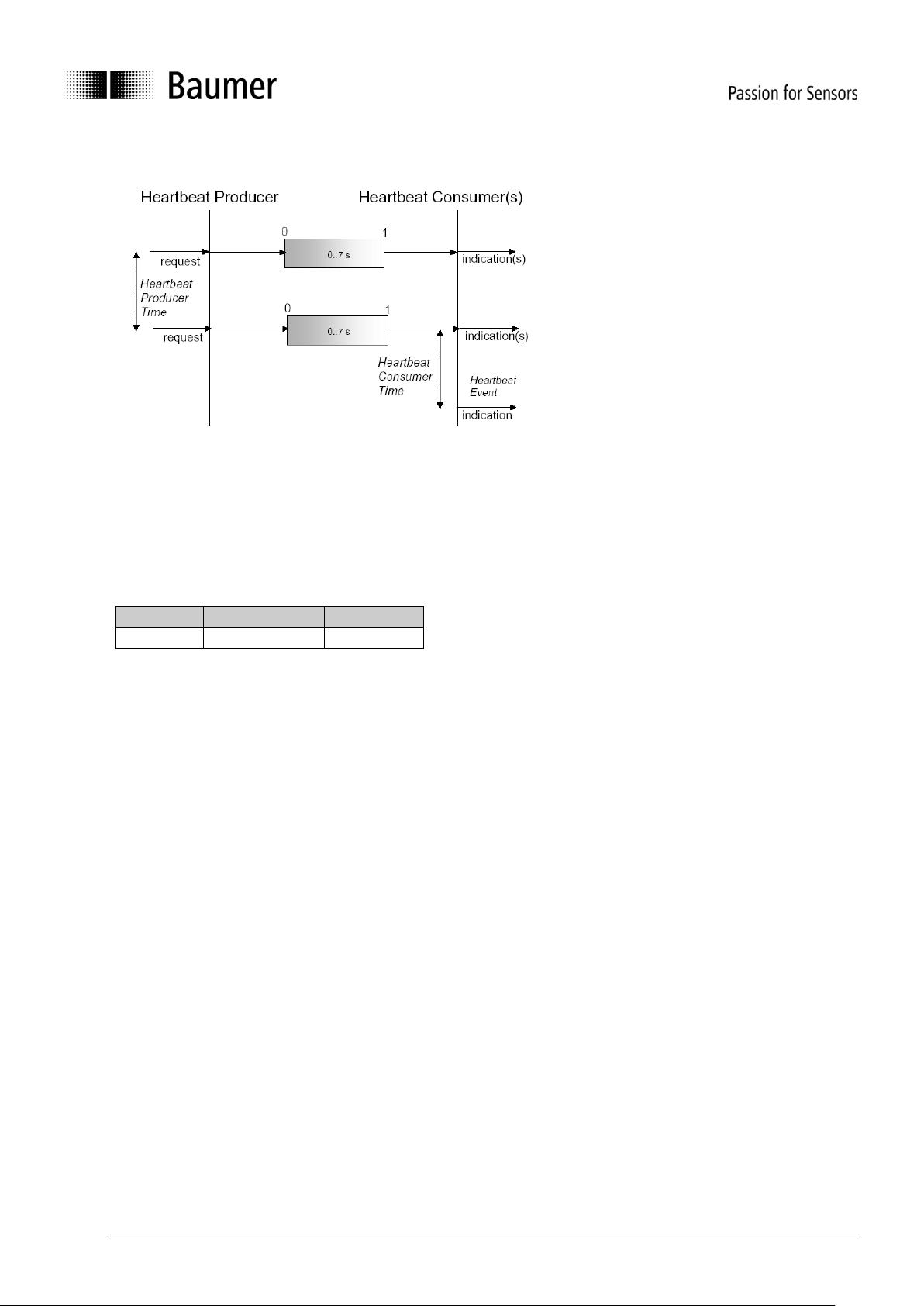
3.3.6.1 Heartbeat protocol
The heartbeat protocol should substitute
the life/node guarding protocol. Heartbeat
is active, if object 2110h Bit5 has the
value '0'. It is highly recommended to
implement the heartbeat protocol for new
device designs. A Heartbeat Producer
transmits the Heartbeat message
cyclically with the frequency defined in
Heartbeat producer time object. One or
more Heartbeat Consumer may receive
the indication. The relationship between
producer and consumer is configurable
via Object Dictionary entries. The
Heartbeat Consumer guards the
reception of the Heartbeat within the
Heartbeat consumer time. If the
Heartbeat is not received within this time
a Heartbeat Event will be generated
"Communication error object 1029h-1h".
Example for a heartbeat protocol
COB-ID
Data/Remote
Byte 0
701h
d
7Fh (127d)
The heartbeat messages consist of the COB ID and one byte. In this byte, the NMT status is supplied.
0: BootUp-Event
4: Stopped
5: Operational
127: Pre-operational
In other words, the sensor is in the pre-operational mode (7Fh = 127).
Page 18
Baumer_GIM500R_CANopen_MA_EN.docx 18/29 www.baumer.com
03.19
3.3.6.2 Layer Setting Services
In the spring of 2000, CiA drafted a new protocol intended to ensure standardized occurrence. The
procedure is described under
Layer Setting Services and Protocol, CiA Draft Standard Proposal 305 (LSS).
The sensor is supplied by us as standard with the node ID 1 and a baud rate of 50 kBaud. Several sensors
can be connected to the bus system with the same node ID. To allow individual sensors to be addressed,
LSS is used.
Each sensor is fitted with its own unique serial number and is addressed using this number. In other words,
an optional number of sensors with the same node ID can be connected to one bus system, and then
initialized via LSS. Both the node ID and also the baud rate can be reset. LSS can only be executed in the
Stopped Mode.
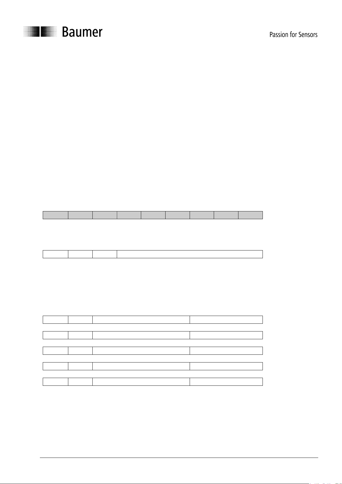
Message structure
COB ID:
Master Slave : 2021 = 7E5h
Master Slave : 2020 = 7E4h
After the COB ID, an LSS command specifier is transmitted.
This is followed by up to seven attached data bytes.
COB ID
cs
Byte 1
Byte 2
Byte 3
Byte 4
Byte 5
Byte 6
Byte 7
Switch Mode Global
7E5h
04h
Mode
reserved
Mode : 0 Operation mode
1 Configuration mode
Selective switch mode
The following procedure can be used to address a certain sensor in the bus system.
7E5h
40h
Vendor ID
reserved
7E5h
41h
Product code
reserved
7E5h
42h
Revision number
reserved
7E5h
43h
Serial number
reserved
7E4h
44h
Mode
reserved
Vendor ID : ECh
Product code : Internal product code for the respective sensor
Revision number : Current revision number of the sensor
Serial number : Unique, consecutive serial number
Mode : The sensor's response is the new mode (0=operating mode; 1=configuration mode)
Page 19
Baumer_GIM500R_CANopen_MA_EN.docx 19/29 www.baumer.com
03.19
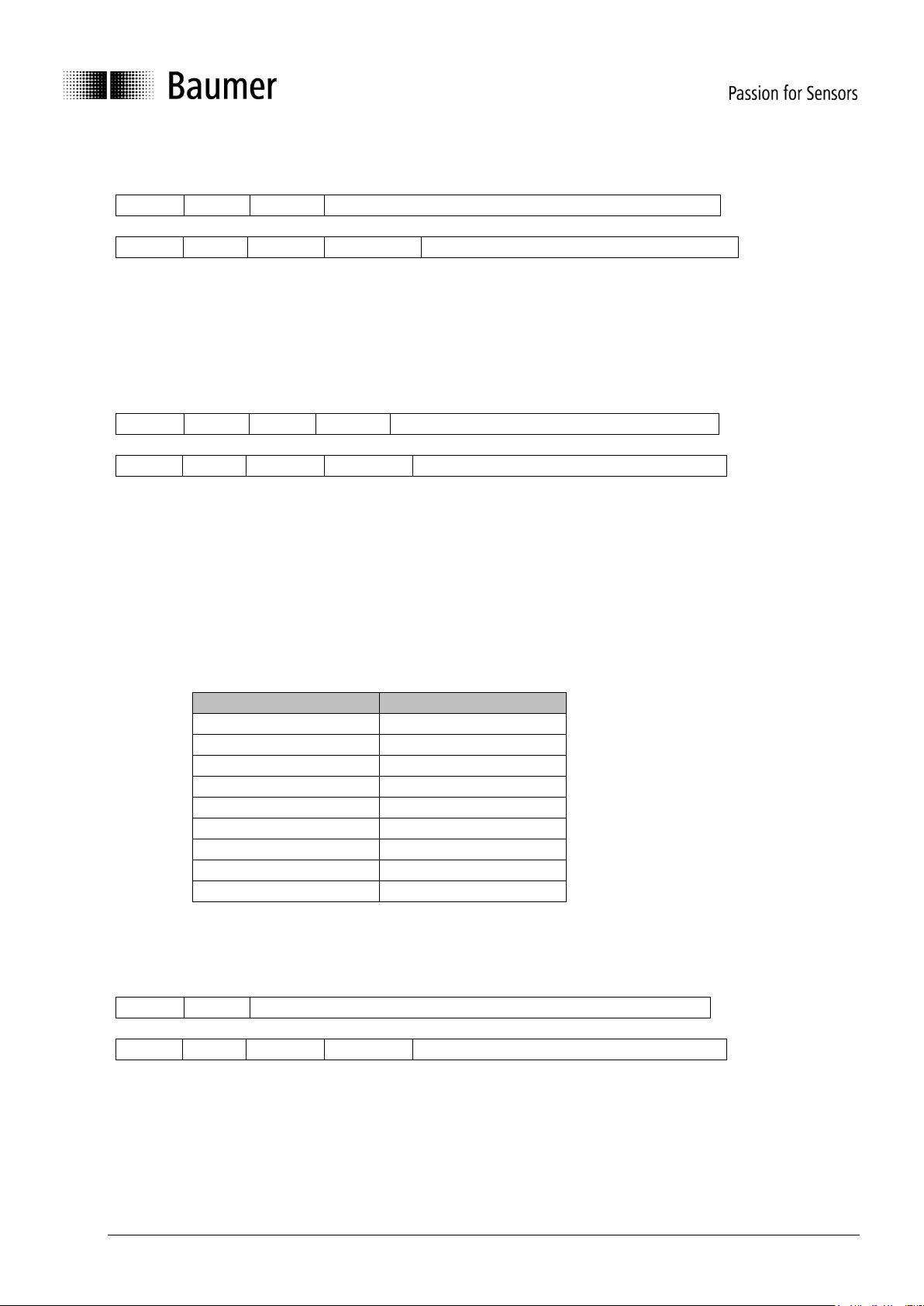
Setting the node ID
7E5h
11h
Node ID
reserved
7E4h
11h
ErrCode
Spec error
reserved
Node ID : The encoder's new node ID
Error code : 0=OK; 1=Node ID outside range; 2..254=reserved; 255Specific error
Specific error : If Error code=255 application-specific error code.
Setting the bit timing
7E5h
13h
tableSel
tableInd
reserved
7E4h
13h
ErrCode
SpecError
reserved
TableSel : Selects the bit timing table 0 : Standard CiA bit timing table
1..127 : Reserved for CiA
128..255 : Manufacturer-specific tables
TableInd : Bit timing entry in selected table (see table below).
Error code : 0=OK; 1=Bit timing outside range; 2..254=reserved; 255Specific error
Specific error : If Error code=255 Application-specific error code.
Standard CiA table
Baud rate
Table Index
1000 kBaud
0
800 kBaud
1
500 kBaud
2
250 kBaud
3
125 kBaud
4
100 kBaud
5
50 kBaud
6
20 kBaud
7
10 kBaud
8
Saving the configuration protocol
This protocol saves the configuration parameters in the EEPROM.
7E5h
17h
reserved
7E4h
17h
ErrCode
SpecError
reserved
Error code : 0=OK;1=Saving not supported;2=Access error;3..254=reserved;255Specific error
Specific error : If error code=255 Application-specific error code.
Page 20
Baumer_GIM500R_CANopen_MA_EN.docx 20/29 www.baumer.com
03.19
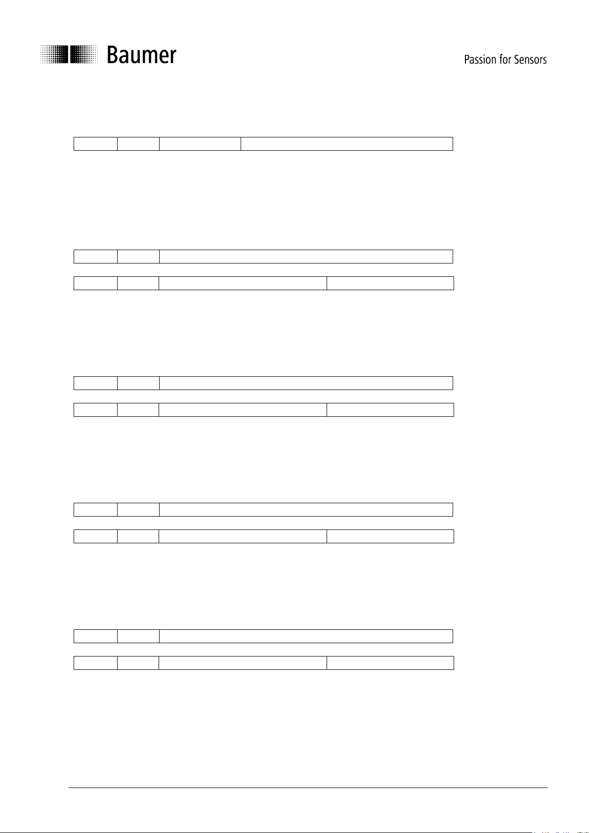
Activate bit timing parameters
The new bit timing parameters are activated with the command specifier 15h.
7E5h
15h
Switch delay
reserved
Switch Delay : Reset delay in the slave in ms.
After the delay, the sensor logs on with the new baud rate.
Request vendor ID
Requesting the vendor ID of a selected sensor
7E5h
5Ah
reserved
7E4h
5Ah
32 bit vendor ID
reserved
Vendor ID : = ECh
Request product code
Request product code of a selected sensor
7E5h
5Bh
reserved
7E4h
5Bh
Product code
reserved
Product code : Manufacturer-dependent product code
Request revision number
Request revision number of a selected sensor
7E5h
5Ch
reserved
7E4h
5Ch
32 bit revision number
reserved
Revision number : Current revision
Request serial number
Request serial number of a selected sensor
7E5h
5Dh
reserved
7E4h
5Dh
32 bit serial number
reserved
Serial number : Unique consecutive serial number of the sensor
Page 21
Baumer_GIM500R_CANopen_MA_EN.docx 21/29 www.baumer.com
03.19
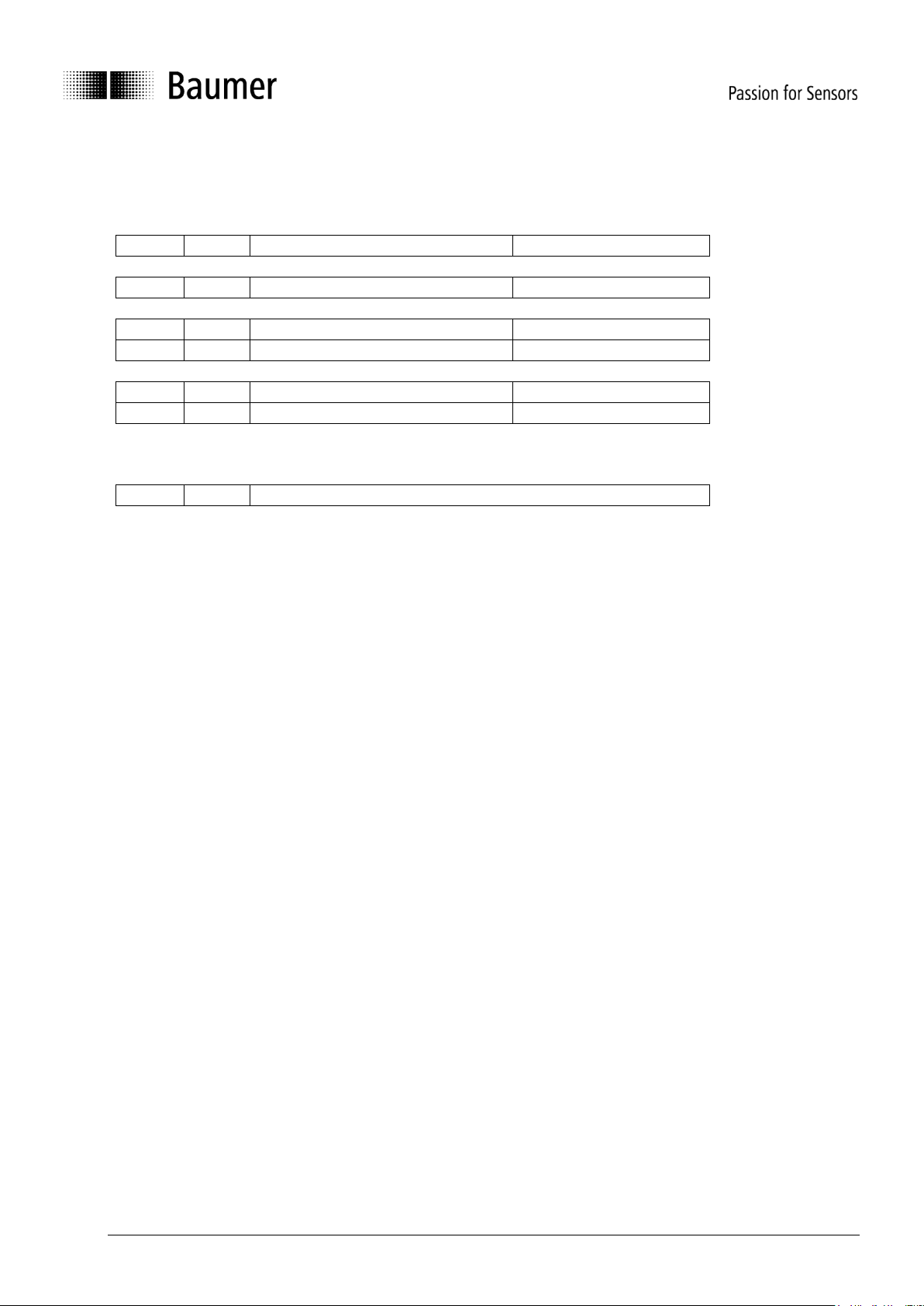
Range request
Sensors can also be searched for within a certain range. For this purpose, the following objects are sent in
sequence:
7E5h
46h
Vendor ID
reserved
7E5h
47h
Product code
reserved
7E5h
48h
Revision number LOW
reserved
7E5h
49h
Revision number HIGH
reserved
7E5h
4Ah
Serial number LOW
reserved
7E5h
4Bh
Serial number HIGH
reserved
Each sensor with the relevant parameters logs on with the following message:
7E4h
4Fh
reserved
3.4 Object Dictionary
According to CiA (CAN in Automation) the objects are subdivided into three groups:
Standard communication objects:
1000h – 1FFFh
Manufacturer-specific objects:
2000h - 5FFFh
Device-specific objects:
6000h - FFFFh
The table below is giving a summary of all SDO objects supported by the inclination sensor.
Object Object number in Hex
Name Name of the parameter
Format Data type
Access ro = ReadOnly, wo = WriteOnly, rw = ReadWrite
Default Default upon first init or restore default
Save yes saved in None Volatile Memory
Page 22
Baumer_GIM500R_CANopen_MA_EN.docx 22/29 www.baumer.com
03.19
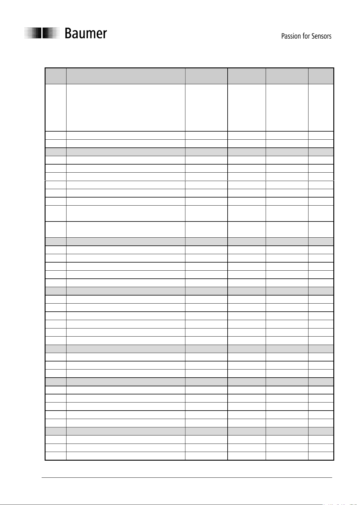
3.4.1 Communication Parameter (CiA DS-301, CiA DS-302 Part 2)
Object
Sub-Index
Name
Format
Access
Default
Save
1000h
Device Type
U32
ro
102019Ah
1001h
Error Register
U8
ro
0h
1002h
Manufacturer Status register
U32
ro
0h
1003h
PreDefined ErrorField
00h
Maximum Subindex
U8
rw
0h
yes
01h
Latest entry
U32
ro
..
..
..
..
..
05h
Oldest entry
U32
ro
1005h
Sync COB-ID
U32
rw
80h
yes
1008h
DeviceName
VSTR
ro
GIM500
1009h
Hardware Version
VSTR
ro
1.00
or higher
100Ah
Software Version
VSTR
ro
1.00
or higher
1010h
Store Parameters
00h
Maximum Subindex
U8
ro
4h 01h
Save all parameters
U32
rw
02h
Communication parameters
U32
rw
03h
Application parameters
U32
rw
04h
Manufacturer- specific parameters
U32
rw
1011h
Restore Default Parameters
00h
Maximum Subindex
U8
ro
4h
01h
Restore all parameters
U32
rw
02h
Restore communication parameters
U32
rw
03h
Restore application parameters
U32
rw
04h
Restore manufacturer specific parameters
U32
rw
1014h
Emergency COB-ID
U32
rw
80h + Node-ID
yes
1016h
Consumer heartbeat time
yes
00h
Maximum Subindex
U8
ro
1h 01h
Consumer heartbeat time
U32
rw
10000h
yes
1017h
Producer Heartbeat Time
U16
rw
0h
yes
1018h
Identity Object
00h
Maximum Subindex
U8
ro
4h
01h
VendorID
U32
ro
ECh
02h
Product Code
U32
ro
40h 03h
Revision Number
U32
ro
Works-defined
yes
04h
Serial Number
U32
ro
Works-defined
yes
1800h
Transmit PDO1 Parameter
00h
Maximum subindex
U8
ro
5h
01h
COB-ID
U32
rw
180h+id
yes
02h
PDO Type
U8
rw
FFh
yes
Page 23
Baumer_GIM500R_CANopen_MA_EN.docx 23/29 www.baumer.com
03.19
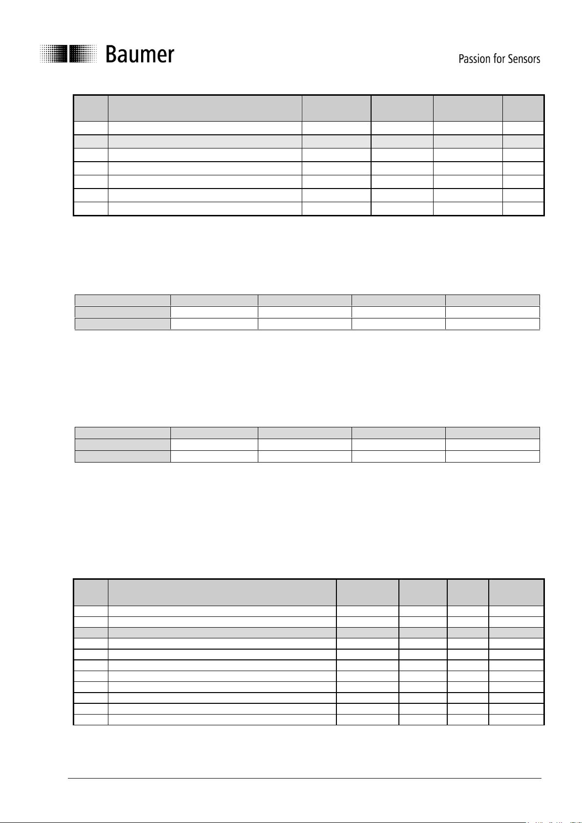
Object
Sub-Index
Name
Format
Access
Default
Save
05h
EventTimer
U16
rw
C8h
yes
1A00h
Transmit PDO1 Mapping
00h
Maximum Subindex
U8
ro
3h
01h
Content of PDO1
U32
ro
65110010h
02h
Content of PDO1
U32
ro
60100010h
03h
Content of PDO1
U32
ro
60200010h
1F80h
NMT startup
U32
rw
0h
yes
3.4.1.1 Store Parameters (1010h)
In order to save parameters object 1010h has to be accessed. In order to avoid storage of parameters by
mistake, storage shall be only executed when a specific signature is written to the appropriate sub-index.
The signature that shall be written is "save":
Signature
MSB
LSB
ISO8859 character
e v a s hex
65h
76h
61h
73h
The data saving process takes a few milliseconds and interrupts the data processing. Be careful to store the
parameters when device data is not used.
3.4.1.2 Restore Parameters (1011h)
In order to avoid the restoring of default parameters by mistake, restoring shall be only executed when a
specific signature is written to the appropriate sub-index. The signature that shall be written is "load":
Signature
MSB
LSB
ISO8859 character
d a o l hex
64h
61h
6Fh
6Ch
The restore is active after a power cycle or a after a CANopen reset.
3.4.1.3 NMT Startup (1F80h)
This object (specified in DS-302 Part 2) determines if the device will go to OPERATIONAL state after reset.
For this option a 08h has to be written to the device. To turn off the auto OPERATIONAL state a 00h has to
be written.
3.4.2 Manufacturer Specific Parameter
Object
Sub-Index
Name
Format
Access
Default
Save
2100h
Baud rate
U8
rw
2h
yes
2101h
Node-ID
U8
rw
1h
yes
2106h
Axis Alignment
00h
Maximum subindex
U8
ro
01h
Axis Mapping
U8
rw
24h
yes
02h
Sign Configuration
U8
rw
0h
yes
2202h
Diagnostic Information
ro
2203h
Layout ID
ro
2204h
Diagnostic Information Switch
ro
2205h
Device Revision
ro
2603h
Digital Filter Configuration
U16
rw
32h
yes
Page 24
Baumer_GIM500R_CANopen_MA_EN.docx 24/29 www.baumer.com
03.19
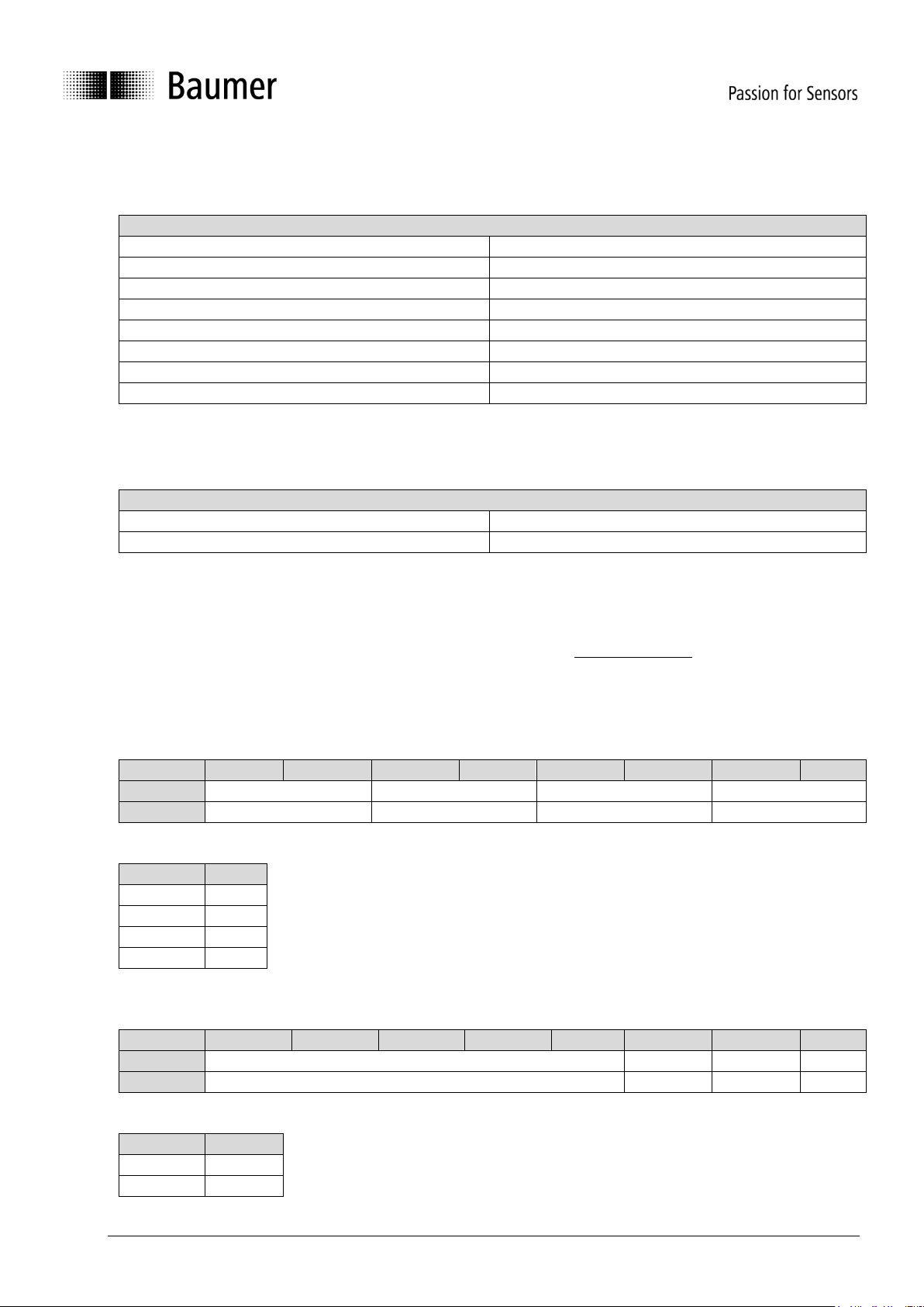
3.4.2.1 Baud rate (2100h)
The baud rate can be changed and read through this object (Additionally to LSS). The following parameters
are possible:
Baud rate (2100h)
Value
Description
2
50kBaud
3
100kBaud
4
125kBaud
5
250kBaud
6
500kBaud
7
800kBaud
8
1000kBaud
The new baud rate will take effect after a restart. 10kBaud is not supported.
3.4.2.2 Node-ID (2101h)
The Node-ID can be changed and read through this object (Additionally to LSS). The parameters are possible:
Node-ID (2101h)
Value
Description
1..127
Node-ID
The new Node-ID will take effect after a restart.
3.4.2.3 Axis Alignment (2106h)
By accessing this object a change of the device orientation can be done (swapping sign and switch axes). A
change of the default orientation can lead to a loss of accuracy and is not suggested.
Axis mapping (subindex 1)
The axes can be switched as shown in the following tables:
Bit Mask:
Bit 7
Bit 6
Bit 5
Bit 4
Bit 3
Bit 2
Bit 1
Bit 0
Reserved
Mapped Z Axis
Mapped Y Axis
Mapped X Axis
Default - 10
01
00
Possible values:
Value (bit)
Axis
00
X-Axis
01
Y-Axis
10
Z-Axis
11
Invalid
Axis sign (subindex 2)
Bit Mask:
Bit 7
Bit 6
Bit 5
Bit 4
Bit 3
Bit 2
Bit 1
Bit 0
Reserved
Z-Axis
Y-Axis
X-Axis
Default
-
0 0 0
Possible values:
Value (bit)
Sign
0
Positive
1
Negative
Page 25
Baumer_GIM500R_CANopen_MA_EN.docx 25/29 www.baumer.com
03.19
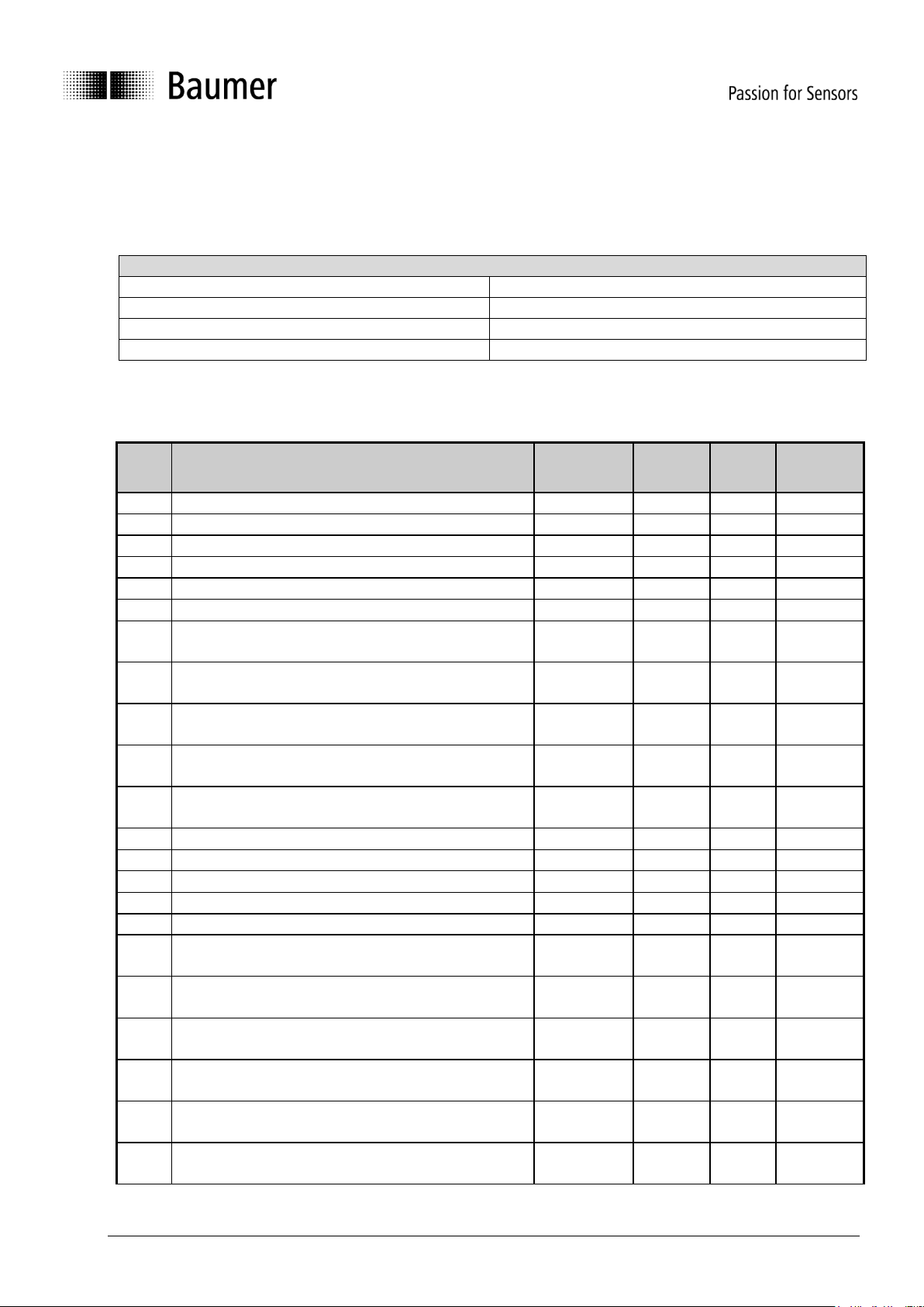
3.4.2.4 Digital Filter Configuration (2603h)
The digital filter’s cut-off frequency can be adjusted through this object. The cut-off frequency has to be
written to the device in 0.1 Hz resolution (i.e. a cut-off frequency of 5 Hz has to be configured by writing a
50d to the device. The following cut-off frequencies are possible:
Digital Filter Configuration (2603h)
Cut-off Frequency
Description
0
Digital Filter deactivated
0.1..1Hz
In 0.1Hz steps
1..30Hz
In 1Hz steps
3.4.3 Device Profile Specific Parameter (CiA DS-410)
Object
SubIndex
Name
Format
Access
Default
Save
6000h
Resolution
U16
rw
64h
yes
6010h
Slope Long 16bit
I16
ro - yes
6011h
Slope long operating parameter X axis
U8
rw
2h
yes
6012h
Slope long 16bit preset value X axis
I16
rw
0h
yes
6013h
Slope long 16bit offset X axis
I16
rw
0h
yes
6014h
Differential slope long 16bit offset X axis
I16
rw
0h
yes
6020h
Slope lateral 16bit X axis
(only for 2-Dimensional)
I16
ro - yes
6021h
Slope lateral operating parameter Y axis
(only for 2-Dimensional)
U8
rw
2h
yes
6022h
Slope lateral 16bit preset value Y axis
(only for 2-Dimensional)
I16
rw
0h
yes
6023h
Slope lateral 16bit offset Y axis
(only for 2-Dimensional)
I16
rw
0h
yes
6024h
Differential slope lateral 16bit offset Y axis
(only for 2-Dimensional)
I16
rw
0h
yes
6110h
Slope Long 32bit X axis
I32
ro - yes
6111h
Slope long 32bit operating parameter X axis
U8
rw
2h
yes
6112h
Slope long 32bit preset value X axis
I32
rw
0h
yes
6113h
Slope long 32bit offset X axis
I32
rw
0h
yes
6114h
Differential slope long 32bit offset X axis
I32
rw
0h
yes
6120h
Slope Lateral 32bit Y axis
(only for 2-Dimensional)
I32
ro - yes
6121h
Slope lateral 32bit operating parameter Y axis
(only for 2-Dimensional)
U8
rw
2h
yes
6122h
Slope lateral 32bit preset value Y axis (only for 2Dimensional)
I32
rw
0h
yes
6123h
Slope lateral 32bit offset Y axis
(only for 2-Dimensional)
I32
rw
0h
yes
6124h
Differential slope lateral 32bit offset
(only for 2-Dimensional)
I32
rw
0h
yes
6511h
Device temperature
I16
ro - yes
Page 26
Baumer_GIM500R_CANopen_MA_EN.docx 26/29 www.baumer.com
03.19
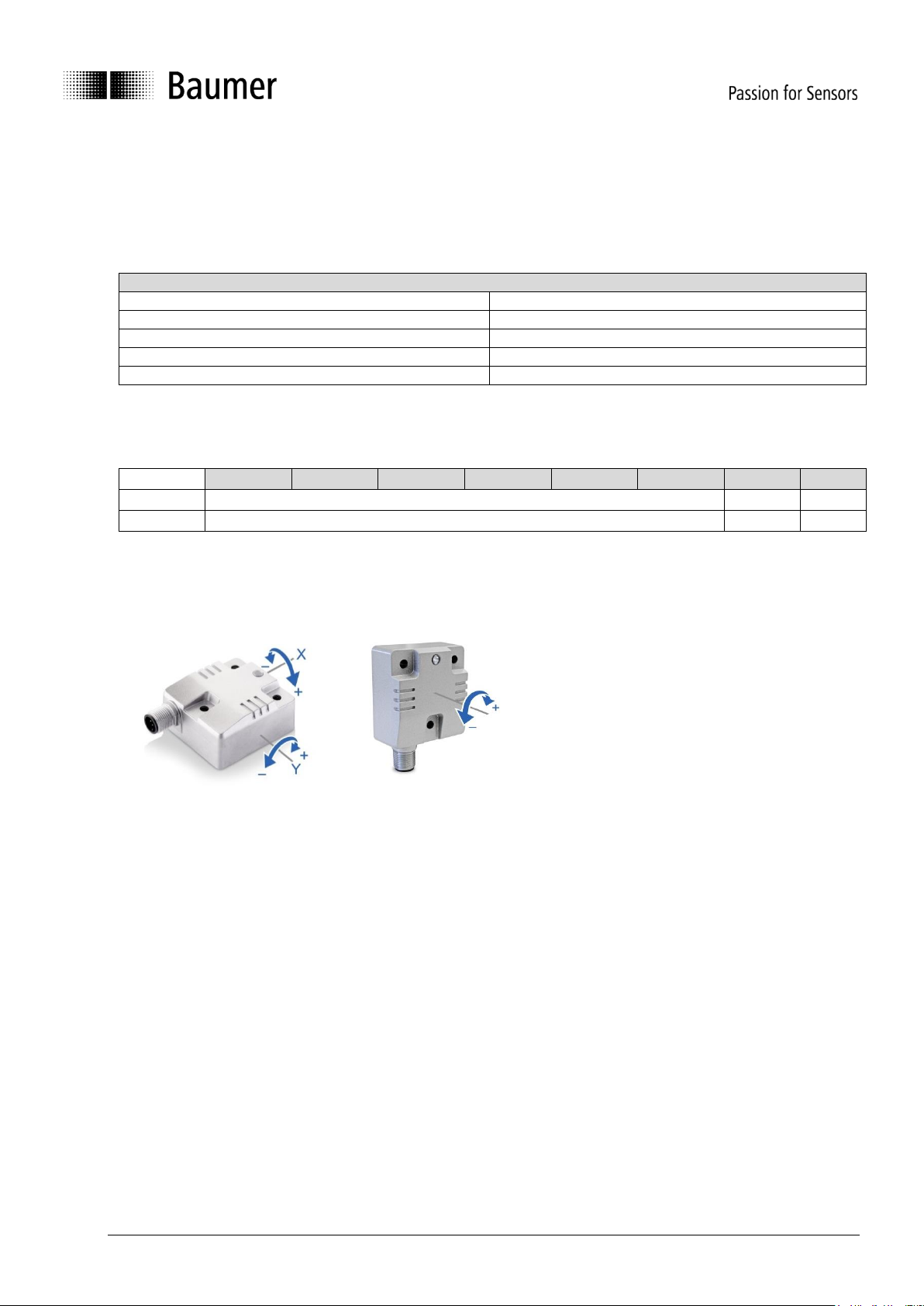
3.4.3.1 Resolution (6000h)
This object shall indicate the resolution of the Slope at X axis (object 6010h) and the Slope a Y axis (object
6020h) objects based on 0,001°.
This resolution is also valid for the 32-bit value objects (6110h and 6120h). Ex works the default value is 0,1°
(64h). The following table describes all possible resolutions:
Resolution (6000h)
Value
Description
01h (1d)
0,001°
Ah (10d)
0,01°
64h (100d)
0,1°
3E8h (1000d)
1°
3.4.3.2 Operating Parameters (6011h/6021h/6111h/6121h)
The above mentioned operating parameter influences the output inclination in the following manner:
Bit Mask:
Bit 7
Bit 6
Bit 5
Bit 4
Bit 3
Bit 2
Bit 1
Bit 0
Reserved
s
i
Default
-
1
0
i = Inversion (0 = Do not enable inversion; 1 = Enable inversion)
s = Scaling (0 = Do not enable scaling; 1 = Enable scaling)
The scaling is active at the factory, the inversion of the sign is deactivated (object value 2H).
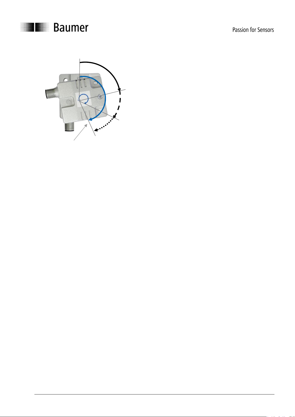
Scaling means that the following equation is applied:
Output slope value = A + B + C
where
A is a physically measured angle (current tilt angle / value);
B is a differential slope offset (The difference slope offset is always added to the current skew);
C is a slope offset (Slope offset is set by the CANopen preset function).
(See chart scaling function)
Page 27
Baumer_GIM500R_CANopen_MA_EN.docx 27/29 www.baumer.com
03.19
Chart Scaling function for 1-dimensional:
The operating parameters are applied for the according slope (i.e. 6011h operating parameter influences
6010h slope).
The 16bit and 32bit values are hardwired internally (i.e. changing the operating parameter at 6011h changes
the operating parameter at 6111h)
3.4.3.3 Offset parameters and calculation
This object shall indicate the application offset of the longitudinal axis. The value shall be given in angular
degrees with the resolution given in object 6000h. The following formula applied:
Slope offset = A – B – C
where
A is a slope preset value;
B is a slope physical measured;
C is a differential slope offset when accessing object a preset object
The 16bit and 32bit values are hardwired internally (i.e. changing the differential offset at 6014h changes the
differential offset at 6114h)
3.4.3.4 Device temperature (6511h)
The device temperature can be read by accessing object 6511h. The value is given in multiples of 1°C. It is
also part of the standard PDO.
A tilt angle
B Differential slope offset
C Slope offset
output tilt angle
Page 28
Baumer_GIM500R_CANopen_MA_EN.docx 28/29 www.baumer.com
03.19
3.5 LED status display
The LED status display is according to DS-303 Part 3 V1.0.0 with some exceptions. The following defined
LED behaviors are overwritten by the application in case of a severe internal error.
3.5.1 CANopen Status LED (Green)
Status LED
State
Description
Single flash
STOPPED
The Device is in STOPPED state
Blinking
PREOPERATIONAL
The Device is in the PREOPERATIONAL state
On
OPERATIONAL
The Device is in the
OPERATIONAL state
Off
Power off
The Device is not powered
3.5.2 CANopen Error LED (Red)
Error LED
State
Description
Single flash
Bus warning
The CAN controller is not
receiving ACK messages (i.e. no
master)
Off
No error
The Device is in working
condition
On
Bus off / Internal Error
The CAN controller is bus off or
an internal error is present.
Page 29
Baumer_GIM500R_CANopen_MA_EN.docx 29/29 www.baumer.com
03.19
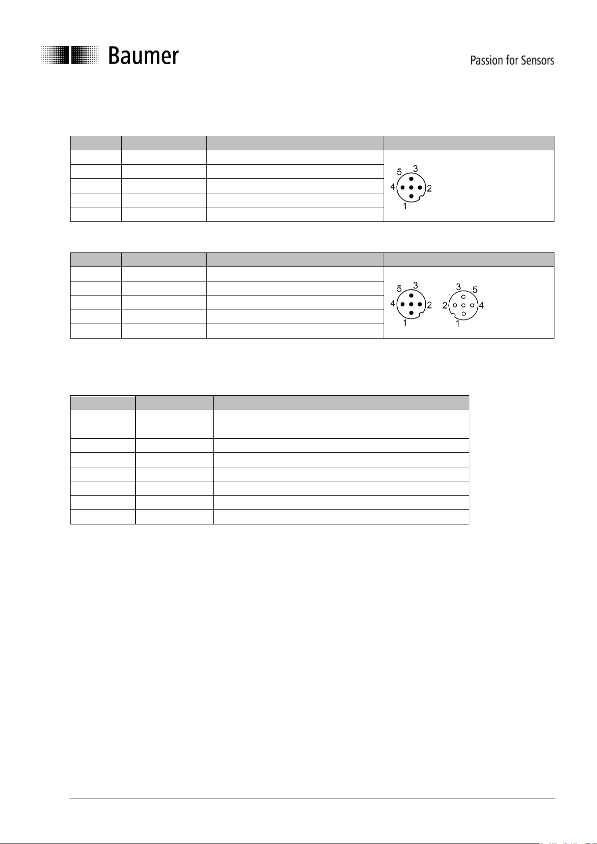
4 Terminal assignment
4.1 M12 flange connector, 5-pin
Pin
Assignment
Description
M12 (male)
1
CAN_GND
Ground connection relating to CAN
2
+Vs
Voltage supply
3
GND
Ground connection relating to +Vs
4
CAN_H
CAN Bus signal (dominant High)
5
CAN_L
CAN Bus signal (dominant Low)
4.2 2xM12 flange connector, 5-pin
Pin
Assignment
Description
M12 (male/female)
1
CAN_GND
Ground connection relating to CAN
2
+Vs
Voltage supply
3
GND
Ground connection relating to +Vs
4
CAN_H
CAN Bus signal (dominant High)
5
CAN_L
CAN Bus signal (dominant Low)
Terminals with the same designation are connected to each other internally and identical in their functions.
Maximum load on the internal clamps Vs-Vs and GND-GND is 1 A each.
4.3 Cable
Core color
Assignment
Description
White
+Vs
Voltage supply
Brown
GND
Ground connection relating to +Vs
Green
n.c.
-
Yellow
n.c.
-
Grey
n.c.
-
Pink
CAN_H
CAN Bus signal (dominant High)
Blue
CAN_L
CAN Bus signal (dominant Low)
Red
CAN_GND
Ground connection relating to CAN
 Loading...