

Page 1
www.basler.com
+1 618.654.2341 (USA)
info@basler.com
Model
AVC Sensing Module
9488800100
Term #
Description
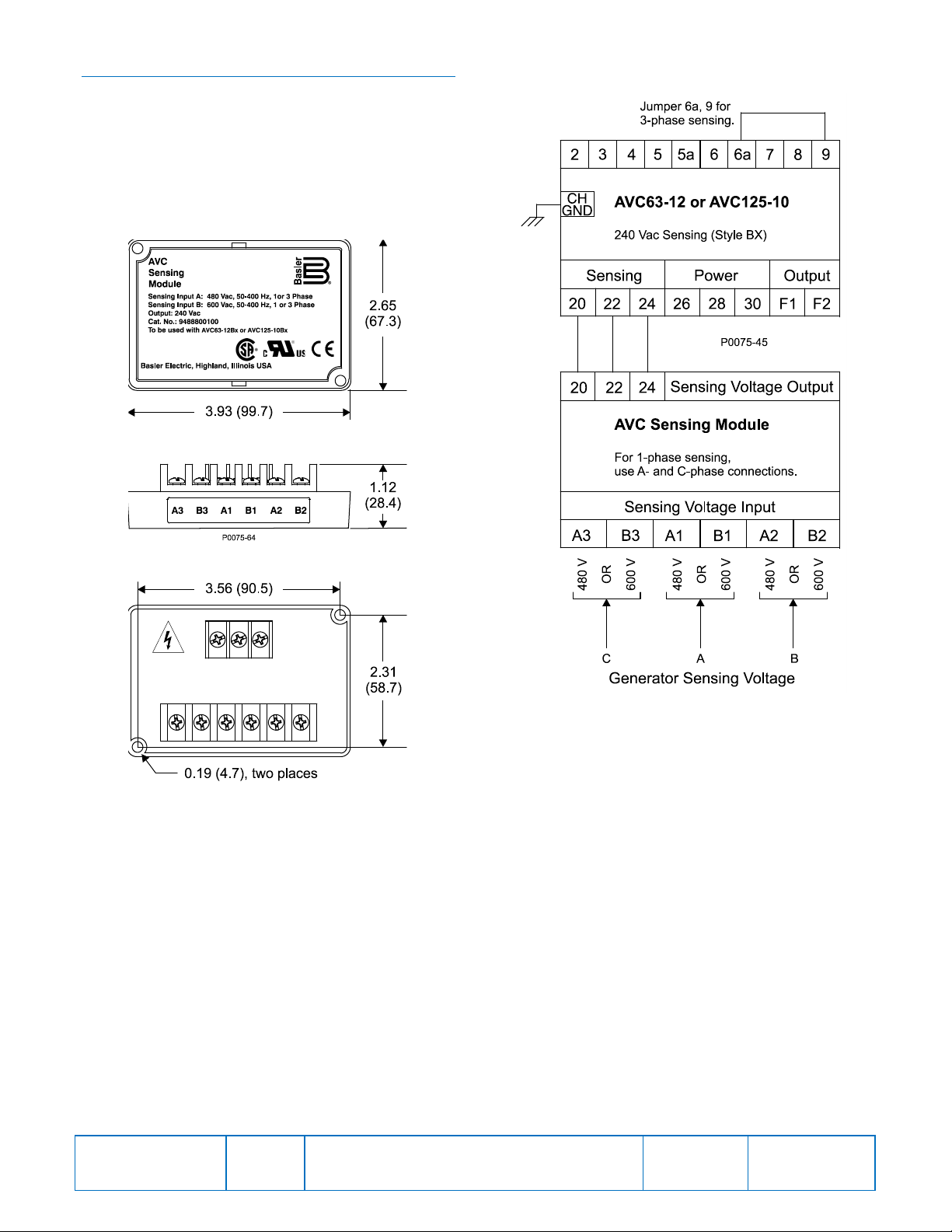
A2
B-phase, 480 Vac nominal sensing voltage
input to AVC Sensing Module
A3
C-phase, 480 Vac nominal sensing voltage
input to AVC Sensing Module
A1
A-phase, 480 Vac nominal sensing voltage
input to AVC Sensing Module
B2
B-phase, 600 Vac nominal sensing voltage
input to AVC Sensing Module
B3
C-phase, 600 Vac nominal sensing voltage
input to AVC Sensing Module
B1
A-phase, 600 Vac nominal sensing voltage
input to AVC Sensing Module
22
A-phase sensing voltage output supplied to
AVC63-12/AVC125-10 terminal 22
24
B-phase sensing voltage output supplied to
AVC63-12/AVC125-10 terminal 24
20
C-phase sensing voltage output supplied to
AVC63-12/AVC125-10 terminal 20
Part Number
INTRODUCTION
The AVC Sensing Module provides a convenient and
cost-effective method for expanding the applica tio ns
where AVC63-12 and AVC125-10 voltage regulators
can be applied. The AVC Sensing Module incr eases
the nominal sensing voltage of style BX AVC63-12
and AVC125-10 voltage regulators from 200/240 Vac
to 480 Vac or 600 Vac. The AVC Sensing Module is
compatible with nominal sensing fr equ encies of
50/60 Hz and 400 Hz.
A compact, rugged (potted) case enables the AVC
Sensing Module to be mounted directly on the
generator. Other than making connections during
installation, the AVC Sensing Module requires no
adjustment or calibration.
SPECIFICATIONS
Sensing Voltage Inputs
Configuration: 1- or 3-phase
Burden: <1 VA
Nominal Frequency: 50, 60, or 400 Hz
Power Dissipation: 2.2 W
480 Vac Nominal Input
Range: 432 to 528 Vac
Terminal Assignments: A1, A2, A3
600 Vac Nominal Input
Range: 540 to 660 Vac
Terminal Assignments: B1, B2, B3
Sensing Voltage Output
Nominal: 200/240 Vac
Range: 180 to 264 Vac
Terminal Assignments: 20, 24, 22
MOUNTING
The AVC Sensing Module is housed in a potted,
plastic case that can be mounted in any convenient
position. Overall module dimensions and panel
drilling dimensions are illust rated in Figure 1.
Mounting Hardware
The AVC Sensing Module can be mounted directly
on a genset using #10-32 or equivalent hardware. A
lock washer should be used between the screw head
and body of the module. Torque applied when
tightening the mounting hardware should not exceed
25 inch-pounds (2.8 N•m).
CONNECTIONS
All AVC Sensing Module connections are located on
the back panel. Sensing voltage is applied to the
lower, six-position terminal block. Sensing voltage is
supplied to the voltage regulator from the upper,
three-position terminal block. Connections consist of
#6 terminal screws. Each terminal accepts a
maximum wire size of 12 AWG (13 mm
2
). When
securing connections, apply no more than 9 in-lb
(1 N•m) of torque to each terminal screw.
Before connecting the module, review the terminal
descriptions listed in Table 1 and the connection
diagram of Figure 2. At any given time, only one of
the two sets of sensing voltage input terminals can be
used. Under no circumstance can both the 480 Vac
and 600 Vac sensing input terminals be connect e d to
a voltage source.
Table 1. Terminal Descriptions
Type Tests
Shock: Withstands 20 G in each of
three mutually perpendicular
planes
Vibration: Withstands 4.5 G at 18 to
2,000 Hz
Physical
Temperature: –40 to 70°C (–40 to 158°F)
operation and storage
Maximum Humidity: 95%, non-condensing
Approximate Weight: 160 g (6 oz.)
Publication
9488800990
For terms of service relating to this product and software, see the Commercial Terms of Products and Services document available at www.basler.com/terms.
Revision
A
Instructions
Date
07/14
Copyright
2014
Page 2
MAINTENANCE
A periodic inspection of the AVC Sensing Module
should be made to ensure that all connections are
clean and tight.
The AVC Sensing Module contains no serviceable
parts. If a failure occurs, replacement of the module
is recommended.
Figure 1. AVC Sensing Module Dimensions
Figure 2. AVC Sensing Module Connections
Publication
9488800990
Revision
A
Instructions
Date
07/14
Page
2 of 2
 Loading...