

Page 1
FOR
VOLTAGE REGULATOR
APR 63-5X
INTRODUCTION
The APR 63-5X Voltage Regulator controls
the dc field power of a conventional, 400 Hz
brushless generator that has a 63 Vdc field
to regulate the generator output voltage. The
APR 63-5X regulates the generator output
by sensing the generator output voltage,
converting it to a dc signal, and comparing
the signal to a reference voltage. An error
signal is developed and used to control the
dc field power in order to maintain a constant generator voltage.
The APR 63-5X is contained in an encapsulated, plastic case.
SPECIFICATIONS
Power Input
Configuration: 1-phase, 400 Hz
Range: 190 to 277 Vac, ±10%
Burden: 650 VA maximum
Dissipation: 25 W maximum
Sensing Voltage
Configuration: 1-phase, 400 Hz
Range
240 Vac: 190 to 240 Vac
480 Vac: 380 to 480 Vac
Burden: 5 VA
Power Output ∗
Continuous:63 Vdc, 5 Adc, 315 W
1-Min. Forcing: 105 Vdc, 8.5 Adc, 893 W
∗ With 240 Vac input power.
DC Exciter Field Resistance
12.6 to 100 Ω
Voltage Adjustment Range
Internal
170 to 264 Vac or 340 to 528 Vac using the
internal voltage adjust.
External
±10% of the nominal value determined by
the internal voltage adjust. A 1 kΩ, 2 W
potentiometer with a locking, screwdriveradjusted shaft is supplied with the APR 635X for remote mounting.
Regulation
Accuracy: ±0.5%
Voltage Drift: <±1% variation for a 50°C
(90°F) change
Response: <1 cycle
Voltage Buildup
Automatic voltage buildup from generator
residual voltage as low as 6 Vac.
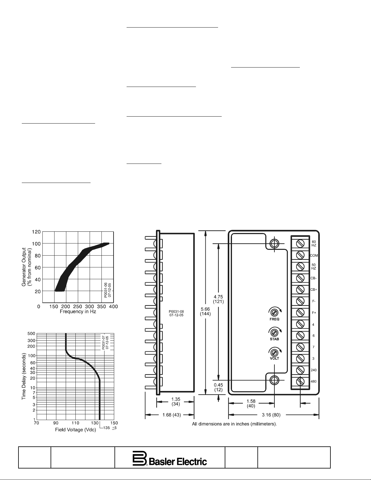
Frequency Compensation
See Figure 1
Overexcitation Shutdown
See Figure 2. If the field voltage exceeds
100 ±5 Vdc, the APR 63-5X automatically
removes the field current after a time delay.
The time delay is inversely proportional to
the magnitude of the detected overvoltage
condition. At approximately 135 ±5 Vdc, the
field voltage is removed instantaneously.
Upon detection of overexcitation and the
resulting field voltage shutdown, the APR
63-5X will not reset or return to an opera-
tional condition until the generator output
drops to less than 6 Vac for 10 seconds.
Shock
Withstands up to 15 G in each of 3 mutually
perpendicular axes.
Vibration
5 to 26 Hz: 1.2 G
27 to 53 Hz: 0.036” double amplitude
54 to 1,000 Hz: 5.0 G
Temperature
Operating: –40 to 60°C (–40 to 140°F)
Storage: –65 to 85°C (–85 to 185°F)
Weight
1,110 g (2.5 lb)
INSTALLATION
Mounting
The APR 63-5X may be mounted in any
position. The APR 63-5X may be mounted
directly on the generator using ¼” hardware.
Select the proper hardware to withstand any
expected transportation and operating conditions. Outline drawings are provided in
Figures 3 and 4.
Connections
APR 63-5X connection diagrams are provided in Figures 5 through 7.
Connecting Procedure
CAUTION
Do not make any connections to the 50 Hz,
60 Hz, or COM terminals.
1. Connect terminals F+ and F– to the field.
Observe proper polarity.
2. Connect terminals 3 and 4 to the generator output. Fuse both leads. If desired, install a shutdown switch.
3. Connect either the 240 or 480 terminal to
the sensing source. Sensing should be
connected line-to-line.
ADJUSTMENTS
Field Flashing
When the regulator is operated with the
generator for the first time, the polarity of the
residual magnetism may be incorrect or of
insufficient magnitude. If the residual voltage
at terminals 3 and 4 is greater than 6 Vac,
replace the regulator. If generator residual
voltage is less than 6 Vac, stop the prime
mover and proceed with the following steps.
CAUTION
The regulator may be damaged if the field is
flashed with the generator in motion.
1. With the prime mover at rest, apply an
ungrounded dc source of not more than
48 Vdc to terminals F+ and F– in series
with a limiting resistor. Use 1 Ω of resistance for each volt from the dc power
source with a power rating of at least 1 W
per ohm. For example, if using a 24 Vdc
source, use a 24 Ω, 24 W resistor.
2. Allow the field to be flashed for approximately 10 seconds before removing the
dc source.
3. If voltage does not build up after performing steps 1 and 2, verify the polarity of the
dc source and perform steps 1 and 2
again.
APR 63-5X Controls
FREQ
This control prevents generator and regulator damage by decreasing the generator
output voltage when the generator frequency decreases. To set the frequency rolloff, perform the following steps:
1. Adjust the generator rpm to the desired
frequency compensation (corner frequency roll-off) point.
2. Adjust the FREQ control until the output
voltage begins to drop-off.
3. Increase the generator rpm to nominal.
The output voltage should return to normal.
STAB
This control allows the generator response
time (and thus voltage stability) to be adjusted. Use an oscilloscope or other voltage
recording device to set the STAB control.
Clockwise rotation of the STAB control
slows response time and counterclockwise
rotation of the STAB control speeds response time. If the STAB control is rotated
too far counterclockwise, the generator voltage may oscillate (hunt).
When adjusting the generator response
time, rotate the STAB control counterclockwise until the system starts oscillating and
then rotate the control clockwise just past
the point where oscillation occurred.
VOLT
Clockwise rotation of the VOLT control increases the generator output voltage.
Replacing the jumper connected across
terminals 6 and 7 with a 1 kΩ, 2 W potentiometer allows a ±10% voltage range adjustment with the nominal level set by the
VOLT control. If a range less or greater than
that provided by the 1 kΩ potentiometer is
desired, a 2 W potentiometer of any value
from 50 to 5,000 Ω may be substituted.
OPERATION
Before proceeding with system startup,
confirm the following:
• Verify that the APR 63-5X specifications
conform with the requirements of the
generator system.
• Ensure that the APR 63-5X has been
installed and connected in accordance
with
Installation, Mounting
tions
.
During periods of prime mover idling, use
the shutdown switch to remove power from
the APR 63-5X.
System Startup
System startup is achieved by performing
the following steps. If the desired results are
not achieved during startup, refer to the
procedures listed under
and
Connec-
Troubleshooting
.
Publication
9168700992
Revision
D
First Printing: 08/93
Revised: 07/05
Copyright
2005
Page 2
1. Start the prime mover and bring it up to
rated speed.
2. Slowly adjust the VOLT control (or external potentiometer) until nominal generator
voltage is achieved.
3. Check stability by applying and removing
load.
4. Check regulation under normal operating
conditions.
5. Reduce the generator frequency to approximately 373 Hz. The generator output
should decrease from this point.
Troubleshooting
If the system does not operate as expected,
use the following information to determine
the cause and remedy.
Generator Voltage Does Not Build
There may be no or incorrect input voltage
applied to APR 63-5X terminals 3 and 4.
Verify the wiring and check the fuses and
shutdown switch.
The field may require flashing—flash the
field.
The overexcitation function may be shutting
the APR 63-5X off. Stop the prime mover
and then restart. Watch for high voltage.
Voltage Builds and then Decays
The voltage adjust circuit may be open. If an
external potentiometer is not used, verify
that a jumper is installed across terminals 6
and 7. If an external potentiometer is used,
the potentiometer may be defective or of the
wrong value. Check the potentiometer and
wiring and correct as necessary.
Voltage Does Not Build to the Rated Value
The jumper across APR 63-5X terminals
CB+ and CB– may be missing—install the
jumper.
Sensing may be connected to the wrong
terminal. Correct the sensing connections as
required.
The setting of the internal or external voltage
adjust may be incorrect. Adjust the VOLT
control or external potentiometer as needed.
Voltage High and Uncontrollable
Generator sensing may not be connected to
the APR 63-5X or may be connected to the
wrong terminal. Correct the sensing connections as needed.
Generator Response is Too Slow or Hunting
The generator load may be excessive or the
generator output may be shorted. Check the
generator load.
The STAB control may be improperly set.
Adjust the STAB control according to the
guidelines provided in
5X Controls, Stab
Adjustments, APR 63-
.
Poor Regulation
The resistance of the field may not be
matched to the capability of the APR 63-5X.
Compare the field resistance with the specified field resistance range of the APR 63-5X.
The APR 63-5X output rating does not meet
the requirement of the generator. Compare
the excitation requirement of the generator
with the specified output range of the APR
63-5X.
The speed of the prime mover may be too
low. Check the speed of the prime mover.
The voltmeter may not be connected at the
same point as the regulator sensing. Verify
the voltmeter connections. Also verify that
an average-sensing voltmeter is used—not
an rms-sensing voltmeter.
Frequency Roll-Off Not Working
The FREQ control may be improperly set.
Adjust the FREQ control according to the
guidelines provided in
5X Controls, Stab
Operational Test
To verify APR 63-5X functionality, perform
the following steps.
1. Connect the regulator as shown in Figure
8 and apply 240 Vac as shown.
2. Adjust the VOLT control fully counterclockwise. Observe that the lamp does
not light.
3. Adjust the VOLT control fully clockwise.
4. Adjust the VOLT control counterclockwise
until the lamp just goes out.
Regulator operation is satisfactory if the
above results are obtained. However, stability must be tested with the regulator and
generator operating.
Adjustments, APR 64-
.
Figure 1. Frequency Compensation Curves
Figure 2. Typical Inverse Time Delay
Characteristic Curves
Page 2 First Printing: 08/93
Revised: 07/05
Figure3. Mounting Dimensions
Revision
D
Publication
9168700992
Page 3

1.094
(27.78)
0.625
(15.88)
0.625
(15.88)
0.25
(6.35)
0.53
(13.49)
D2717-08
06-06-00
0.375
(9.53)
NOTE: All dimensions are in inches (millimeters).
0.125
(3.18)
0.81
(20.64)
Figure 4. External Voltage Adjust Potentiometer (Basler P/N 17727)
A
P0031-09
07-13-05
B
C
GEN
M
Field
1
250 V, 5 A fast acting, high
interrupting capacity fuses.
2
Shutdown switch.
External voltage adjust.
3
Jumper terminals 6 and 7 if
not used.
60
Hz
COM
50
Hz
1 1
2
3
CB- CB+ F- F+ 4 6 7 3 240 480
APR 63-5X
Figure 5. 240 Vac, Single-Phase Interconnection Diagram
Publication
9168700992
GEN
M
Field
1
250 V, 5 A fast acting, high
interrupting capacity fuses.
2
Shutdown switch.
External voltage adjust.
3
Jumper terminals 6 and 7 if
not used.
60
Hz
COM
50
Hz
Revision
D
1 1
2
3
CB- CB+ F- F+ 4 6 7 3 240 480
APR 63-5X
P0031-12
07-15-05
Figure 6. 480 Vac Interconnection Diagram
First Printing: 08/93
Revised: 07/05
A
B
C
N
Page
3
Page 4

GEN
M
Field
1 1
Isolation Tra nsformer
A
B
C
N
1
250 V, 5 A fast acting, high
interrupting capacity fuses.
2
Shutdown switch.
External voltage adjust.
3
Jumper terminals 6 and 7 if
not used.
60
Hz
COM
50
Hz
3
CB- CB+ F- F+ 4 6 7 3 240 480
APR 63-5X
2
P0031-13
07-15-05
Figure 7. Isolation Transformer Interconnection Diagram
60
Hz
J1
COM
Light Bulb
100 watts
10 ohms
10 watts
J3 J2
50
CB- CB+ 4 6 7 3 240 480
Hz
F- F+
APR 63-5X
240 Vac
P0031-14
07-15-05
Figure 8. Test Setup Diagram
Page 4 First Printing: 08/93
Revised: 07/05
Revision
D
Publication
9168700992
 Loading...