


 Loading...
OPERATOR MANUAL
Basil 4600 Cage and Rack Washer Basil 4602 Cage and Rack Washer
(2008-06-12) |
P122997-341 |

A WORD FROM STERIS CORPORATION
This manual contains important information on proper use and maintenance of this equipment. Refer to SECTION 6, ROUTINE MAINTE- NANCE, for instructions in routine care of this washer. All personnel involved in the use and maintenance of this equipment must carefully review and comply with the warnings, cautions and instructions contained in this manual. These instructions are important to protect the health and safety of personnel operating a
Basil® 4600 Cage and Rack Washer or a Basil® 4602 Cage and Rack Washer and should be retained in a conveniently accessible area for quick reference.
This equipment is specifically designed only for the uses outlined in this manual.
Complete instructions for uncrating and connecting utilities, as well as equipment drawings, have been provided. If they are missing, contact STERIS for replacement copies, providing the serial and model numbers of the unit.
Advisory IMPORTANT: A listing of the Safety Precautions to be observed when operating this washer can be found in SECTION 1. Do not operate the equipment until you have become familiar with this information.
Any alteration of this equipment not authorized or performed by STERIS could void the warranty, adversely affect its efficacy and violate national, state and local regulations.
To help assure operators are adequately trained in the safe use of the equipment, STERIS recommends that:
•all personnel who operate or maintain the equipment are trained in its operation and in its safe use;
•personnel working with toxic chemicals and vapors (if applicable) have comprehensive instructions in the unit, washing process, relevant health hazards and methods to detect the escape of toxic materials;
•there is regular training of all personnel concerned with the operation and maintenance of the equipment; attendance records are maintained; and the evidence of understanding is demonstrated.
©2008, STERIS Corporation. All rights reserved. |
Printed in Canada. |
i
Introduction |
Operator Manual |
122997-341 |

Indications For Use
Service Information
The Basil 4600 Cage and Rack Washer and Basil 4602 Cage and Rack Washer are heavy duty, large capacity hydrospray washers designed for thorough, efficient cleaning of cages, racks, debris pans and miscellaneous items used in the care of laboratory animals.
These units are specifically designed to only process goods as outlined in this manual. If there is any doubt about a specific material or product, contact the manufacturer of the product for the recommended washing technique.
A thorough preventive maintenance program is essential to safe and proper unit operation. This manual contains maintenance schedules and procedures which should be followed for satisfactory equipment performance.
Customers are encouraged to contact STERIS concerning extended service maintenance agreements to give their equipment planned maintenance assuring equipment performance according to factory specifications.
A global network of skilled service specialists can provide periodic inspections and adjustments to help ensure low-cost peak performance. STERIS representatives can provide information regarding annual maintenance agreements. STERIS carries a complete line of accessories for use with this washer. Please contact STERIS for details.
Basil 4600 Cage and Rack Washer and Basil 4602 Cage and Rack Washer meet the application requirements of the following standard:
•61010-1 Electrical Equipment for measurement; control and laboratory use; Part 1 General requirements as certified by Underwriters Laboratories (UL).
|
|
|
|
|
Manufacturer: |
ISO 13485 |
|
|
Corporation STERIS |
ISO 9001 |
|
|
Canada |
Certified |
|
|
Beauport, Qc, CANADA |
Facility |
|
|
|
|
|
|
|
|
|
The base language of this document is ENGLISH. Any translations must be made from the base language document.
Sales and Service:
STERIS Corporation
5960 Heisley Road
Mentor, Ohio 44060 440-354-2600 • 800-444-9009
www.steris.com
ii
122997-341 |
Operator Manual |
Introduction |

|
|
|
|
|
TABLE OF CONTENTS |
|
|
|
|
|
|
Section |
|
|
|||
Number |
Description |
Page |
|||
|
|
|
|
||
|
|
A WORD FROM STERIS CORPORATION................................................................. |
I |
||
|
|
Advisory ........................................................................................................................................................... |
|
i |
|
|
|
Indications For Use ......................................................................................................................................... |
|
ii |
|
|
|
Service Information ......................................................................................................................................... |
|
ii |
|
1 |
SAFETY PRECAUTIONS ..................................................................................... |
|
1-1 |
||
2 |
INSTALLATION CHECKLIST ............................................................................... |
|
2-1 |
||
|
|
2.1 |
General .................................................................................................................................................. |
|
2-1 |
|
|
2.1.1 Technical specifications ................................................................................................................. |
|
2-1 |
|
|
|
2.1.2 Amperage and Power Consumption |
.............................................................................................. |
2-1 |
|
|
|
2.1.3 Permissible Environmental Conditions ........................................................................................... |
2-2 |
||
|
|
2.1.4 Noise Level ..................................................................................................................................... |
|
2-2 |
|
|
|
2.1.5 Seismic Anchorage System ........................................................................................................... |
|
2-2 |
|
|
|
2.2 |
Installation Checklist .............................................................................................................................. |
|
2-2 |
|
|
2.3 |
Chemical Additives Specifications ........................................................................................................ |
|
2-4 |
3 |
COMPONENT IDENTIFICATION .......................................................................... |
|
3-1 |
||
|
|
3.1 |
General .................................................................................................................................................. |
|
3-1 |
|
|
3.2 POWER-OFF/STANDBY Switch ............................................................................................................. |
|
3-2 |
|
|
|
3.3 |
Interior Light ........................................................................................................................................... |
|
3-2 |
|
|
3.4 |
Control Panel ......................................................................................................................................... |
|
3-3 |
|
|
3.4.1 Display Screen ............................................................................................................................... |
|
3-3 |
|
|
|
3.4.2 Cycle Status Touch Pads ............................................................................................................... |
|
3-3 |
|
|
|
3.4.3 Manual Control Touch Pads ........................................................................................................... |
|
3-4 |
|
|
|
3.4.4 Program Touch Pads ..................................................................................................................... |
|
3-4 |
|
|
|
3.5 |
Printer .................................................................................................................................................... |
|
3-5 |
|
|
3.5.1 Printer Function Switch ................................................................................................................... |
|
3-5 |
|
|
|
3.5.2 Sample Printout .............................................................................................................................. |
|
3-6 |
|
|
|
3.6 |
Unload-Side Control Panel .................................................................................................................... |
|
3-7 |
|
|
3.7 |
Oscillating Jet System ........................................................................................................................... |
|
3-7 |
|
|
3.8 |
Safety System ........................................................................................................................................ |
|
3-8 |
|
|
3.9 |
Heat Exchanger ..................................................................................................................................... |
|
3-9 |
|
|
3.10 Automatic Detergent Injection System ...................................................................................... |
|
.......... 3-9 |
|
|
|
3.11 Reusable-Throwaway Acid Detergent System .................................................................................. |
3-10 |
||
|
|
3.12 NonRecirculated Final Rinse ........................................................................................................... |
|
3-10 |
|
|
|
3.13 Feeder Bottle Washing System ......................................................................................................... |
|
3-11 |
|
Continued...
iii
122997-341 |
Operator Manual |
Table of Contents |

TABLE OF CONTENTS (Cont’d)
|
|
|
|
Section |
|
|
|
Number |
Description |
Page |
|
|
|
|
|
|
3 COMPONENT IDENTIFICATION (Cont’d) |
|
|
3.14 |
Automatic Water Flush System for Two Racks .................................................................................. |
3-11 |
|
3.15 |
Drain Discharge Cooldown with Side Tank and Temperature Guarantee ........................................ |
3-12 |
|
3.16 |
Drain Discharge Cooldown System with Cold Water Injection Only ................................................. |
3-13 |
|
3.17 |
Exhaust Fan ....................................................................................................................................... |
3-13 |
|
4 WASHER OPERATION ......................................................................................... |
4-1 |
|
4.1 |
Before Operating Washer ...................................................................................................................... |
4-1 |
4.2 |
How to Load Washer ............................................................................................................................. |
4-2 |
4.3 |
Cycle Operation ..................................................................................................................................... |
4-4 |
4.4 |
Review and Print Specific Cycle Program ........................................................................................... |
4-17 |
4.5 |
Stop Cycle Operation .......................................................................................................................... |
4-19 |
4.6 |
Abort Cycle Operation ......................................................................................................................... |
4-19 |
4.7 |
Extend Cycle Phase Time .................................................................................................................... |
4-20 |
4.7.1 During a Cycle ............................................................................................................................. |
4-20 |
|
4.7.2 Prior to Starting a Cycle ............................................................................................................... |
4-20 |
|
4.8 |
Bypass Phase ...................................................................................................................................... |
4-22 |
4.9 |
Shutdown Procedure ........................................................................................................................... |
4-22 |
4.10 Manual Control Mode ........................................................................................................................ |
4-23 |
|
4.10.1 Accessing Manual Control Mode ............................................................................................... |
4-24 |
|
4.10.2 FILL Function .............................................................................................................................. |
4-24 |
|
4.11 DRAIN Function ................................................................................................................................. |
4-25 |
|
4.11.1 Draining Sump ........................................................................................................................... |
4-25 |
|
4.11.2 Draining Alkaline Tank ............................................................................................................... |
4-26 |
|
4.11.3 Draining Acid Tank ..................................................................................................................... |
4-27 |
|
4.11.4 Draining Cooldown Tank ............................................................................................................ |
4-27 |
|
4.12 PUMP/DRV Function .......................................................................................................................... |
4-28 |
|
4.13 DRIVE Function .................................................................................................................................. |
4-29 |
|
5 CYCLE PROGRAMMING ...................................................................................... |
5-1 |
|
5.1 |
Program Touch Pads ............................................................................................................................. |
5-1 |
5.2 |
Change Values Mode ............................................................................................................................ |
5-1 |
5.3 |
Programming Cycle Values ................................................................................................................... |
5-3 |
5.3.1 Pre-Wash ........................................................................................................................................ |
5-4 |
|
5.3.2 Alkaline Wash ................................................................................................................................. |
5-4 |
|
5.3.3 Acid Wash ...................................................................................................................................... |
5-5 |
|
5.3.4 Rinse .............................................................................................................................................. |
5-7 |
|
Continued...
iv
Table of Contents |
Operator Manual |
122997-341 |

TABLE OFTABLECONTENTSOF CONTENTS(Cont’d)
|
|
|
|
|
|
Section |
|
|
|||
Number |
Description |
Page |
|||
|
|
|
|
|
|
5 |
CYCLE PROGRAMMING (Cont’d) |
|
|
||
|
|
5.4 |
Programming Operating Values .......................................................................................................... |
|
5-10 |
|
|
5.5 |
Programming Values with Access Code Enabled ............................................................................... |
5-11 |
|
6 |
ROUTINE MAINTENANCE ................................................................................... |
|
6-1 |
||
|
|
6.1 |
General .................................................................................................................................................. |
|
6-1 |
|
|
6.2 |
Preventive Maintenance Schedule ........................................................................................................ |
|
6-2 |
|
|
6.3 |
Daily Cleaning Procedures .................................................................................................................... |
|
6-4 |
|
|
6.4 |
Weekly Cleaning Procedures ................................................................................................................ |
|
6-5 |
|
|
6.4.1 Clean Washer Exterior..................................................................................................................... |
|
6-5 |
|
|
|
6.4.2 Clean Washer Interior ..................................................................................................................... |
|
6-5 |
|
|
|
6.4.3 Clean Spray Jets and Headers ...................................................................................................... |
|
6-6 |
|
|
|
6.4.4 Inspect Self-Cleaning Screen ........................................................................................................ |
|
6-7 |
|
|
|
6.5 |
Monthly Cleaning Procedures ............................................................................................................... |
|
6-8 |
|
|
6.5.1 Remove Hard Water Deposits From Chamber and Accessories .................................................. |
6-8 |
||
|
|
6.6 |
Routine Maintenance ............................................................................................................................. |
|
6-9 |
|
|
6.6.1 Grease Exhaust Fan Bearings ....................................................................................................... |
|
6-9 |
|
|
|
6.6.2 Clean Drain Discharge Side Tank ................................................................................................ |
|
6-10 |
|
|
|
6.6.3 Clean Drain Discharge Temperature Control Probe .................................................................... |
6-12 |
||
|
|
6.6.4 Replace Detergent Squeeze Tube ............................................................................................... |
|
6-13 |
|
|
|
6.6.5 Replacing Detergent Container ................................................................................................... |
|
6-14 |
|
|
|
6.7 |
Printer Paper ........................................................................................................................................ |
|
6-15 |
|
|
6.7.1 Printer Paper Roll Replacement ................................................................................................... |
|
6-15 |
|
|
|
6.7.2 Storing Thermal Paper ................................................................................................................. |
|
6-17 |
|
7 |
TROUBLESHOOTING.......................................................................................... |
|
7-1 |
||
|
|
5.1 |
Test Procedure – Allen-Bradley Control ................................................................................................ |
|
5-1 |
|
|
5.2 |
Test Procedure – Siemens Control ........................................................................................................ |
|
5-7 |
v
122997-341 |
Operator Manual |
Table of Contents |

LISTTABLEOFOFFIGURESCONTENTS (Cont’d)
|
|
|
|
|
FigureSection |
|
|
||
Number |
Description |
Page |
||
|
|
|
|
|
2 |
INSTALLATION CHECKLIST |
|
||
|
|
2-1 |
Shutoff Valves and Disconnect switch ................................................................................................. |
2-1 |
3 |
COMPONENT IDENTIFICATION |
|
||
|
|
3-1 |
Washer Components - Basil 4600 (Typical) ........................................................................................ |
3-1 |
|
|
3-2 |
Control Column ................................................................................................................................... |
3-2 |
|
|
3-3 |
Control Panel ....................................................................................................................................... |
3-3 |
|
|
3-4 |
Printer .................................................................................................................................................. |
3-5 |
|
|
3-5 |
Sample Printout ................................................................................................................................... |
3-6 |
|
|
3-6 |
Sample Alarm Printout ......................................................................................................................... |
3-6 |
|
|
3-7 |
Unload-Side Control Panel .................................................................................................................. |
3-7 |
|
|
3-8 |
Oscillating Jet System ......................................................................................................................... |
3-7 |
|
|
3-9 |
Safety Cables ...................................................................................................................................... |
3-8 |
|
|
3-10 |
Heat Exchanger .................................................................................................................................. |
3-9 |
|
|
3-11 |
Non-Recirculated Final Rinse Spray Header .................................................................................... |
3-10 |
|
|
3-12 |
Drain Discharge Side Tank (Typical) ................................................................................................ |
3-12 |
|
|
3-13 |
Exhaust Fan ....................................................................................................................................... |
3-13 |
4 |
WASHER OPERATION |
|
||
|
|
4-1 |
Manual Drain Valve ............................................................................................................................. |
4-1 |
|
|
4-2 |
Accessories ......................................................................................................................................... |
4-3 |
|
|
4-3 |
Manual Control Mode Flow Chart ...................................................................................................... |
4-23 |
5 |
CYCLE PROGRAMMING |
|
||
|
|
5-1. Program Touch Pads ............................................................................................................................ |
5-1 |
|
6 |
ROUTINE MAINTENANCE |
|
||
|
|
6-1. Spray Header Flush Plug ..................................................................................................................... |
6-6 |
|
|
|
6-2. Self-Cleaning Screen ............................................................................................................................ |
6-7 |
|
|
|
6-3. Exhaust Fan Grease Fittings ................................................................................................................ |
6-9 |
|
|
|
6-4. Manual Drain Valve ............................................................................................................................ |
6-10 |
|
|
|
6-5. Replace Squeeze Tube ...................................................................................................................... |
6-13 |
|
|
|
6-6. Replacing Detergent Container........................................................................................................... |
6-14 |
|
|
|
6-7. Printer Paper Roll Replacement ......................................................................................................... |
6-16 |
|
vi
Table of Contents |
Operator Manual |
122997-341 |

SAFETY PRECAUTIONS |
1 |
|
|
|
|
|
|
|
The following Safety Precautions must be observed when operating or servicing this equipment. WARNING indicates the potential for personal injury and CAUTION indicates the potential for damage to equipment. For emphasis, certain Safety Precautions are repeated throughout the manual. It is important to review ALL Safety
Precautions before operating or servicing the unit.
WARNING – PERSONAL INJURY AND/OR EQUIPMENT DAMAGE HAZARD:
Always wear appropriate Personal Protective Equipment (PPE) when cleaning or removing debris from bottom of wash chamber and over suction plate.
Only STERIS or STERIS-trained service personnel should make repairs and adjustments to this equipment. Maintenance done by inexperienced, unqualified personnel or installation of unauthorized parts could cause personal injury, invalidate warranty, or result in costly damage. Contact STERIS regarding Service options.
Regularly scheduled preventive maintenance, in addition to faithful performance of minor maintenance described within this manual, is required for safe and reliable operation of this equipment. Contact STERIS to schedule preventive maintenance.
To open doors from inside wash chamber, pull EMERGENCY STOP cables. Washer operation will automatically stop. Then, push firmly on door panel using shoulder and upper arm, applying upper body force.
WARNING – PERSONAL INJURY HAZARD:
Items in washing cart may move during processing and be filled with residual hot water or protrude from cart at the end of the cycle. Always wear appropriate personal protective equipment (PPE) and carefully remove items from cart.
Never perform cleaning of wash chamber until full cycle has been completed. If cycle has not been completed, contaminated debris or water may remain in the bottom of the wash chamber.
Keep fingers away from door hinges to prevent pinching.
To prevent tipping, place biggest and heaviest items on the lower levels of accessory cart.
WARNING – ELECTRIC SHOCK AND/OR BURN HAZARD:
Disconnect all utilities to washer before servicing. Do not service washer unless all utilities have been properly locked out. Always follow local occupational health and safety regulations, as well as electric and plumbing codes.
1-1
Safety Precautions |
Operator Manual |
122997-341 |

WARNING – CHEMICAL BURN AND/OR EYE INJURY HAZARD:
Washer chemicals are caustic and can cause adverse effects to exposed tissues. Do not get in eyes, on skin, or attempt to swallow. Read and follow precautions and instructions on chemical label and in Material Safety Data Sheet (MSDS) prior to handling detergent containers, or servicing detergent injection pumps, tank, and lines. Wear appropriate Personal Protective Equipment (PPE) whenever handling chemicals or servicing chemical injection pumps, tank, and lines.
Wear appropriate Personal Protective Equipment (PPE) when removing clamps and replacing squeeze tubes. Residual chemicals might remain in used squeeze tubes. If chemical contacts skin or eyes, immediately flush with running water for at least 10 minutes. If contact was with eyes, seek medical attention.
Wear gloves and eye protection when using a descaling product. Avoid contact with eyes or skin. If spilled or splashed, flush with plenty of water for 15 minutes. If swallowed, DO NOT induce vomiting. Administer an alkali with plenty of water. Seek medical attention immediately.
WARNING – BURN HAZARD:
Allow unit to cool down before performing any service on mechanical components and on piping. Components and piping become very hot during operation.
Inner surfaces of washer are very hot after cycle completion. Operator should wear appropriate Personal Protective Equipment (PPE) and avoid all contact with inner walls when entering chamber to unload washer.
Pipes may be extremely hot.
When cycle is complete, partially open chamber door and allow chamber and load to cool. Hot steam may escape through door opening if door is fully opened after a cycle.
WARNING – SLIPPING HAZARD:
To avoid slippery floor conditions, keep floor dry. Promptly wipe up any spilled liquids or condensation. If spilled liquids are detergents or other chemicals, follow safety precautions and handling procedures set forth on detergent or chemical label and/or Material Safety Data Sheet (MSDS).
CAUTION – POSSIBLE EQUIPMENT DAMAGE:
Always use non-foaming chemical for effective cleaning and proper pump and water level control operation. Follow manufacturer’s recommendations for amount of chemical to be used.
Always use a silicone lubricant to lubricate squeeze tubes. Petroleum-based lubricants, such as Vaseline®1 or grease, will cause squeeze tubes to melt.
Avoid product damage. Always select a cycle appropriate for items being processed.
1 Vaseline is a trademark of Chesebrough Pond's Incorporated.
1-2
122997-341 |
Operator Manual |
Safety Precautions |

CAUTION – POSSIBLE EQUIPMENT DAMAGE (Cont’d):
Before operating unit, always position manifolded Bottle Washing Cart over central water inlet connector. If manifolded accessory is not positioned correctly, damage may result and unit will be unable to effectively wash load.
Do not process load using Bottle Washing Cart when Automatic Floor Tilting option is activated. If Automatic Floor Tilting is used, manifolded water inlet and washer will be damaged.
Remove all cellulose-type bedding from cages and pans before processing. Cellulose bedding can clog filters and piping.
Use nonabrasive cleaners when cleaning unit. Follow directions on containers and rub in a back-and- forth motion (in same direction as surface grain). Abrasive cleaners will damage stainless steel. Cleaners rubbed in a circular motion applied with a wire brush or steel wool will scratch and dull stainless steel. Do not use these cleaners on painted surfaces.
When choosing a detergent, select one with a low chloride content. Detergents with a high chloride content can corrode stainless steel.
1-3
Safety Precautions |
Operator Manual |
122997-341 |
The tables below contain symbols which may be on your Basil 4600 Cage and Rack Washer or 4602 Cage and Rack Washer components:
Table 1-1. Definition of Symbols on Unit
Symbol |
Definition |
Protective Earth (Ground).
Warning! Risk of Electrical Shock.
Attention! Refer to Manual for Further Instructions.
Fuse Identification.
Pump Rotation
|
Table 1-2. Definition of Symbols on Identification Nameplate |
|
|
|
|
Symbol |
|
Definition |
|
|
|
MODEL |
|
Model Number of the Unit. |
|
|
|
S/N |
|
Serial Number of the Unit. |
|
|
|
V 3~ |
|
Volt, Number of the Phase (Three) Alternating Current. |
|
|
|
WIRE |
|
Number of Wires of the Unit, Ground not Included. |
|
|
|
YEAR |
|
Year of Manufacture of the Unit. |
|
|
|
kW |
|
Power Rating of the Unit |
|
|
|
A |
|
Amperage. |
|
|
|
Hz |
|
Hertz – Frequency of the Unit. |
|
|
|
1-4
122997-341 |
Operator Manual |
Safety Precautions |

INSTALLATION CHECKLIST |
2 |
|
|
|
|
|
|
|
IMPORTANT: A listing of the Safety Precautions to be observed when operating and servicing this Cage and Rack Washer can be found in SECTION 1. Do not install equipment until you have become familiar with this information.
2.1 General An equipment drawing, showing all utility and space requirements, was supplied with the washer. Clearance space specified on equipment drawing is necessary for ease of installation and to assure proper operation and maintenance of equipment. If documents are missing or misplaced, contact STERIS giving unit serial, equipment, and model numbers. Replacement copies will be sent to you promptly.
2.1.1 Technical
specifications
2.1.2 Amperage and Power
Consumption
These specifications are intended to describe technical information given on nameplate of your washer and to state other relevant information. Check equipment drawing or identification nameplate, located inside control door, above main electrical box, for proper voltage and amperage.
Basil® 4600 Cage and Rack Washer and Basil® 4602 Cage and Rack Washer operate on:
•208 V~, three-phase, 60 Hz
•480 V~, three-phase, 60 Hz.
A protective ground conductor is required (Class 1 Equipment). Installation Category is Overvoltage II.
Refer to equipment drawing (920-505-383 for Basil 4600; 920-505- 871 for Basil 4602 or custom equipment drawing) for proper connection.
IMPORTANT: Customer is responsible for compliance with applicable codes and regulations.
Maximum currents and power consumptions, are indicated on nameplate.
2-1
Installation Checklist |
Operator Manual |
122997-341 |
2.1.3 Permissible |
This unit is designed to give optimal results under the following con- |
Environmental Conditions |
ditions: |
-Indoor use only;
-Altitude of operation up to 6562 ft (2000 m);
-Temperature 41°F to 104°F (5°C to 40°C);
-Maximum relative humidity is 80% for temperatures up to 88°F (31°C) decreasing linearly to 50% relative humidity at 104°F (40°C);
-Installation Category II;
-Pollution Degree 2.
2.1.4Noise Level Equivalent Sound Pressure Level: 84 dB (A). Results determined
according to ISO-3746: 1995 Standard: Acoustics Determination of Sound Power Levels of Noise Sources Survey Method.
2.1.5 Seismic Anchorage
System
2.2 Installation
Checklist
Shutoff Valves
Disconnect Switch
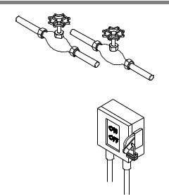
Figure 2-1. Shutoff Valves and
Disconnect Switch
2-2
Washer can be built to seismic zone 3 and 4 requirements.
After installing washer according to Uncrating/Installation Instructions (P910000-015), complete the following checklist to assure complete and correct installation. Contact STERIS to schedule a technician to test your installation and demonstrate proper equipment operation.
Shutoff valves (not provided by STERIS) should be installed on steam and water supply lines to unit (see Figure 2-1). Shutoff valves must be capable of being locked in OFF position only and in compliance with occupational health and safety regulations, as well as electric and plumbing codes for any special requirements that may pertain to installation of this unit.
Disconnect switches (not provided by STERIS) should be installed in electric supply lines near unit (see Figure 2-1). Disconnect switches must be capable of being locked in OFF position only. Disconnect switches must be installed in electric supply line near unit (within 10' [3 m] of equipment) and in compliance with occupational health and safety regulations, as well as electric and plumbing codes for any special requirements that may pertain to installation of this unit.
NOTE: If washer is installed next to other equipment, shutoff valves and disconnect switch should be placed so that service can be shut off to any one unit.
122997-341 |
Operator Manual |
Installation Checklist |
Washer is positioned, as shown on equipment drawing, with required service clearance space and in relation to building supply lines.
Basil 4600 Cage and Rack Washer and Basil 4602 Cage and Rack Washer must be installed between two walls, with a keylocked service door, so washer service side is not accessible to operator.
Building steam line provides maximum dynamic steam pressure and flow rate to washer as specified on equipment drawing.
Drip leg with steam trap installed in steam supply line.
Building hot water line supplies water to washer at pressure and temperature specified on equipment drawing.
Building cold water line supplies water to washer at pressure specified on equipment drawing.
Electrical supply for washer is as specified on equipment drawing.
Condensate returns are sized as specified on equipment drawing.
Vent connections are sized as specified on equipment drawing.
Recirculation pump pressure is within 25 to 60 psig.
Recirculation pump motor rotating in direction shown by arrow.
Self-cleaning screen assembly functioning properly.
Carriage drive motor rotating in direction shown by arrow.
Carriage drive system functioning properly.
Carriage drive motor amperage within rating indicated on the motor.
Optional exhaust fan rotating in direction shown by arrow.
All piping is leak-free.
Chamber sump steam coil functioning properly.
Door safety switch(es) functioning properly.
Cabinet joints are completely sealed, no leaks (for verification, run machine for 1/2 hour).
Door(s) easily opens from inside of chamber.
Safety cables immediately stop washer operation when pulled.
Each gear box plastic cap removed and replaced with air vent provided.
Floor surrounding unit has non-slip surface.
IMPORTANT: After a few weeks of operation, inspect unit for leaks. Retighten all clamps and connections.
2-3
Installation Checklist |
Operator Manual |
122997-341 |

2.3 Chemical Additives
Specifications
The selection of chemical additives is open for customer preference; however, in order to achieve optimal performance, the selected chemical additives must meet as a minimum, the following specifications:
|
Use Dilution |
pH |
|
|
|
|
|
Product |
Range oz/ |
Other Applicable |
|||||
Range |
|||||||
Description |
gal (mL/L) |
Requirements |
|
||||
at Use |
|
||||||
|
Dilution |
|
|
|
|
||
|
|
|
|
|
|
||
|
|
|
|
||||
Alkaline |
1/4 - 4 |
|
Liquid, non-foaming, and vis- |
||||
9.0 - 12.0 |
cosity |
below |
200 |
SSU |
|||
Chemicals |
(2-32) |
||||||
|
(0.0004623 ft2/sec). |
|
|||||
|
|
|
|
||||
|
|
|
|
|
|
||
Acidic |
1/4 - 4 |
|
Liquid, |
non-foaming, |
free |
||
3.0 - 6.0 |
rinsing, |
and viscosity |
below |
||||
Chemicals |
(2-32) |
||||||
|
200 SSU (0.0004623 ft2/sec). |
||||||
|
|
|
|||||
|
|
|
|
||||
|
|
|
Liquid, non-foaming, phos- |
||||
Descalers |
1/2 -2 |
<2.5 |
phoric acid-based, and vis- |
||||
cosity |
below |
200 |
SSU |
||||
|
|
|
|||||
|
|
|
(0.0004623 ft2/sec). |
|
|||
|
|
|
|
|
|
|
|
NOTE: When choosing and using chemicals, take note of the following:
1)Follow chemical label recommendations for concentration of chemical to use.
2)Follow chemical manufacturer's recommendations to determine the temperature of the WASH treatment.
3)Follow chemical manufacturer's recommendations for the amount of chemical used according to water hardness.
To achieve maximum cleaning efficiency, select chemical appropriate to soil type being processed. STERIS recommends the following chemicals:
•Cage-Klenz® 100 Alkaline Cage Wash Detergent - (Alkaline) formulated to remove urine, scale, animal fats, oils and other organic soils from cage materials.
•Cage-Klenz® 200 Acid-Based Cage Wash Detergent - (Acidic) formulated to remove urine, scale, animal fats, oils and other organic soils from cage materials.
•Liquid Descaler Acid-Based Scale Remover - for removing scale and other hard water deposits. For use in animal care centers.
NOTE: Certain products may not be available in your area. Contact your STERIS representative for availability of these products and for ordering information.
IMPORTANT: STERIS does not promote, recommend, nor endorse the use of any other type of chemical additives in the processing of articles in the Basil 4600/4602 Cage and Rack Washers, such as drying agents, strong alkaline detergents (pH>12), alcohol rinses and liquid germicides including hypochloric acid (bleach).
2-4
122997-341 |
Operator Manual |
Installation Checklist |
COMPONENT IDENTIFICATION |
3 |
|
|
|
|
|
|
|
IMPORTANT: A listing of the Safety Precautions to be observed when operating and servicing this Cage and Rack Washer can be found in SECTION 1. Do not install equipment until you have become familiar with this information.
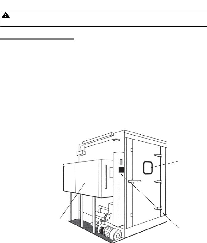
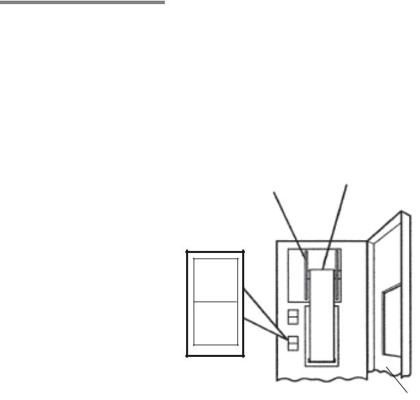
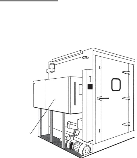
3.1 General Become familiar with location and function of all major components and controls, as well as their function before operating this unit (see Figure 3-1).
Two models are available: Basil® 4600 Cage and Rack Washer and
Basil® 4602 Cage and Rack Washer.
•Basil4600:
Wash Chamber: 46" W x 85" H x 92" L (1168 x 2159 x 2336 mm) Overall Unit: 82" W x 102" H x 99" L (2082 x 2590 x 2514 mm) Equipped with Reusable - Throwaway Detergent Tank
•Basil 4602:
Wash Chamber: 46" W x 85" H x 188" L (1168 x 2159 x 4775 mm) Overall Unit: 82" W x 102" H x 195" L (2082 x 2590 x 4953 mm) Equipped with Reusable - Throwaway Detergent Tank
Each model is equipped with a user-programmable microcomputer control system capable of storing up to twelve treatment cycles to process a wide variety of loads. Computer control system monitors and automatically controls all cycle operations.
Chamber Door
and Viewing
Window
Reusable-Throwaway
Detergent Tank
Control Console
Figure 3-1. Washer Components - Basil 4600 (Typical)
3-1
Component Identification |
Operator Manual |
122997-341 |
3.2 POWER-OFF/
STANDBY Switch
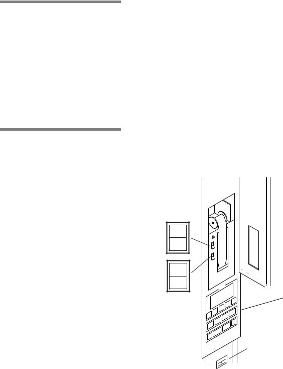
3.3 Interior Light
POWER-OFF/STANDBY switch, located behind the printer door, includes two settings which direct operation of control (see Figure 3- 2):
•POWER – Press top portion of POWER-OFF/STANDBY switch to initialize control and place control in Ready Mode.
•OFF/STANDBY – Press bottom portion of POWER-OFF/ STANDBY switch to initiate Shutdown Cycle and place control in Standby Mode.
NOTE: Control should be placed in Standby Mode for last cycle of the day and when washer is not in use for an extended period of time.
IMPORTANT: POWER-OFF/STANDBY switch does not turn off electrical power to unit.
Interior light, can be manually controlled by operator through a toggle switch located behind printer door, below control panel, on load side (see Figure 3-2). Interior light illuminates wash chamber when loading or unloading washer, or it can left ON during a whole washing cycle to view washing process.
POWER
OFF
STANDBY
VALUES
Control Panel
INTERIOR LIGHT |
|||
|
|
|
|
|
ON |
OFF |
|
|
|
|
|
|
|
|
|
Figure 3-2. Control Column
3-2
122997-341 |
Operator Manual |
Component Identification |
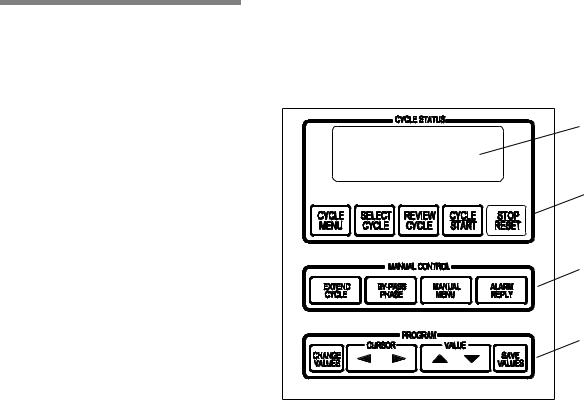
3.4 Control Panel Control Panel is used to direct all washer functions (see Figure 3-3). Operator may program specific cycles, review and select cycles, start, stop or reset cycle operation, extend or bypass cycle phases, and monitor cycle performance.
Display Screen
Cycle Status
Touch Pads
Manual Control
Touch Pads
Program Touch
Pads
Figure 3-3. Control Panel
3.4.1 Display Screen Two line alpha-numeric screen displays cycle program data on demand, in-cycle performance data and operator instructions. Display screen also indicates certain abnormal conditions that may occur during a cycle.
3.4.2 Cycle Status Touch |
• CYCLE MENU touch pad – press to view first cycle menu. Press |
Pads |
again to advance screen to next cycle menu. Three menus are |
|
available, each with four cycles. |
|
• SELECT CYCLE touch pad – press until desired cycle name |
|
flashes. |
|
NOTE: When a displayed cycle name or phase value is selected, |
|
corresponding word or digit flashes. |
|
• REVIEW CYCLE touch pad – press to review cycle phases and |
|
values programmed for selected cycle. |
|
• CYCLE/START touch pad – press once to display name of |
|
selected cycle. Press a second time to start cycle. |
|
NOTE: Selected cycle name remains on screen for 5 seconds |
|
3-3 |
Component Identification |
Operator Manual |
122997-341 |
after pressing CYCLE/START touch pad once. To start a cycle, CYCLE/START touch pad must be pressed a second time while selected cycle name is displayed. If touch pad is not pressed within 5 seconds, screen automatically returns to Cycle Menu.
•STOP/RESET touch pad – press once to stop cycle operation. Press a second time to abort cycle and return screen to cycle menu.
NOTE: When cycle is stopped, press Cycle/Start touch pad once to
resume cycle operation. Cycle operation resumes at beginning of
interrupted phase function (i.e., filling, recirculating, draining). When
cycle is aborted, cycle operation is discontinued and cycle must be
re-started from the beginning.
3.4.3 Manual Control Touch |
• EXTEND PHASE touch pad – press to temporarily increase |
Pads |
selected phase time. On completion of cycle, phase time returns |
|
to programmed setpoint. |
•BYPASS PHASE touch pad – press to bypass specific phase in progress and advance cycle to next phase.
NOTE: Bypass Phase touch pad can only be used when a cycle is in progress. During cycle, filling and draining functions can not be bypassed. In addition, a phase can not be bypassed if Temperature Guarantee feature is selected for that phase.
•MANUAL MENU touch pad – press to view washer functions which can be controlled manually.
•ALARM REPLY touch pad – press to turn off alarm buzzer and acknowledge displayed alarm message. Refer to SECTION 7, TROUBLESHOOTING, for specific alarm conditions and corrective actions.
3.4.4Program Touch Pads Program touch pads allow programming of twelve distinct cycles
and changing of previously programmed cycle values to process different types of loads. Cycle programming may be limited by access code to ensure process integrity. Refer to SECTION 5, CYCLE PROGRAMMING, for details on cycle programming and access code feature.
•CHANGE VALUES touch pad – press to access Change Values mode. Change Values mode allows authorized operators to change user-programmable items. Refer to SECTION 5, CYCLE PROGRAMMING, for details about Change Values Mode.
NOTE: Examples of user-programmable items include cycle name, phase temperature, phase time, and questions regarding phase options (e.g., retention of final rinse water).
3-4
122997-341 |
Operator Manual |
Component Identification |
•CURSOR (left or right) touch pad – press until item to be changed (word, letter, or number) flashes.
•VALUE (up or down) touch pad – depending on item flashing (selected), press to either toggle between answer selections or scroll through alphabet and numbers 0 through 9.
NOTE: Alphabet includes characters for an underline (_) and a space ( ).
•SAVE VALUES touch pad – press to save changes made, exit Change Values mode and return screen to cycle menu.
3.5Printer Printer records pertinent cycle data on 2-1/4" wide thermal paper
(see Figure 3-4). Refer to SECTION 6.7, PRINTER PAPER, for information on changing paper roll and storing thermal paper.
3.5.1Printer Function Switch Printer Function Switch controls the following two printer functions:
•PRINT – press top of Printer Function Switch to generate a print of alkaline and acid detergent setpoints (if conductivity option) and all RTD temperatures (actual water temperature).
•PRINT VALUES – press bottom of Printer Function Switch to generate a complete printout of all cycle parameters.
Thermal Paper
Take-Up Spindle
VALUES
Printer Door
Figure 3-4. Printer
3-5
Component Identification |
Operator Manual |
122997-341 |
3.5.2Sample Printout The following is an example of a typical cycle printout (see Figure 3-5):
•POWER UP
When POWER-OFF/STANDBY switch is set to POWER, generated printout lists time and date control was turned on and unit’s serial number.
•CYCLE START
When CYCLE/START touch pad is pressed twice to begin selected cycle, generated printout lists name of cycle started, time and date cycle was started, cycle number, and unit number.
•IN-CYCLE PERFORMANCE
During a cycle, generated printout lists start and end time of each phase, along with actual temperature of solution/water in chamber sump.
* CONTROL ON |
|
8:32:31A |
|
|
- - - - - - - - - - - - - - - - - - - - - - - - |
|
|
||
CYCLE – CYCLE 1 |
|
|||
|
||||
- - - - - - - - - - - - - - - - - - - - - - - - |
|
Cycle |
||
CYCLE START |
|
8:37:33A |
||
|
|
|||
CYCLE DATE |
|
4/24/05 |
|
Start |
CYCLE NUMBER |
00000001 |
|
||
UNIT NUMBER |
|
3600000000 |
|
|
|
|
|||
PHASE |
TIME |
F |
|
|
- - - - - - - - - - - - - - - - - - - - - - - - - - - - - - - - - |
|
|||
PRE-WASH |
8:38:03A |
141.5 |
|
|
|
8:39:03A |
135.0 |
|
|
DET-WASH |
8:41:33A |
146.3 |
|
Cycle-In |
|
8:46:33A |
144.2 |
|
|
|
|
|
||
RINSE 1 |
8:49:10A |
183.5 |
|
Performance |
|
8:50:40A |
182.7 |
|
|
|
|
|
||
RINSE 2 |
8:53:00A |
184.0 |
|
|
|
8:54:30A |
182.5 |
|
|
F. RINSE |
8:57:20A |
184.3 |
|
|
|
8:58:50A |
183.8 |
|
|
EXHAUST |
8:59:50A |
183.8 |
|
|
- - - - - - - - - - - - - - - - - - - - - - - - - - - - - - - - - |
of-End |
|||
CYCLE COMPLETE |
9:01:20A |
|||
MAX WASH TEMP= |
146.3F |
|
PerformanceCycle Summary |
|
MAX RINSE TEMP= |
184.3F |
|
||
DOOR OPENED |
|
9:03:42A |
|
|
CYCKE TIME= |
|
0:23:27 |
|
|
- - - - - - - - - - - - - - - - - - - - - - - - - - - - - - - - |
- |
|
||
READY TO UNLOAD |
|
|
||
- - - - - - - - - - - - - - - - - - - - - - - - - - - - - - - - - |
|
|||
Figure 3-5.Sample Printout
•END-OF-CYCLE PERFORMANCE SUMMARY
At end of a cycle, generated printout lists time cycle was completed, maximum wash and rinse temperatures reached during cycle, and total cycle processing time.
•ALARM CONDITION
When an alarm condition occurs, generated printout lists type of alarm and time it occurred (see Figure 3-6). Once operator presses Alarm Reply touch pad, generated printout lists time alarm was acknowledged.
PHASE |
TIME |
F |
- - - - - - - - - - - - - - - - - - - - - - - - - - - - - - - - - - - - |
||
PREWASH |
10:15:20A |
163.5 |
|
10:17:02A |
166.8 |
* ALARM |
|
10:18:02A |
SUMP |
|
|
TOO LONG IN FILL |
|
|
- - - - - - - - - - - - - - - - - - - - - - - - - - - - - - - - - - - - |
||
ALARM ACKNOWLEDGED |
|
|
|
AT 10:18:15A |
|
|
|
|
Figure 3-6. Sample Alarm Printout
3-6
122997-341 |
Operator Manual |
Component Identification |

3.6 Unload-Side
Control Panel
An additional control column is installed on unload side of unit (see Figure 3-7). The unload side control panel features same touch pads and display screen as load end control panel.
All washer functions except POWER-OFF/STANDBY and PRINT/ PRINT VALUES can be directed from this control panel, and display screen concurrently shows same cycle performance data as loadside control panel.
3.7 Oscillating Jet
System
Additional Chamber |
Second Control |
|
Column |
||
Door on Unload Side |
||
|
Figure 3-7. Unload-Side Control Panel
Oscillating jet system consists of two spray headers, one on each side of wash chamber, suspended from an oscillating carriage (see Figure 3-8). Each spray header is equipped with machined jets angled to reach all surfaces of load.
Oscillating jet system travels back and forth along length of chamber during recirculating/spraying phase function. Jet system is equipped with a safety clutch that stops movement of oscillating carriage if an obstruction is detected.
|
Oscillating |
Spray |
Carriage |
|
|
Headers |
Spray Jets |
|
Figure 3-8. Oscillating Jet System
3-7
Component Identification |
Operator Manual |
122997-341 |
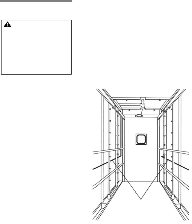
3.8 Safety System
WARNING – PERSONAL INJURY AND/OR EQUIPMENT DAMAGE HAZARD: To open doors from inside wash chamber, pull EMERGENCY STOP cables. Washer operation will automatically stop. Then, push firmly on door panel using shoulder and upper arm, applying upper body force.
Chamber doors are equipped with a safety switch to stop washer operation if door is opened during a cycle and to prevent start of washer operation if door is not securely closed.
Chamber doors are also equipped with a spring-loaded, explosion relief type safety latch. Door can be easily opened when pushed from inside of wash chamber.
Two stainless-steel, red-coated safety cables are installed inside wash chamber, one along each side (see Figure 3-9). If cable is pulled, washer operation is immediately stopped.
Oscillating jet system is equipped with a mechanical clutch to disengage carriage drive if an obstruction is encountered, preventing damage to spray headers and load items.
Load-side and unload-side control panels are equipped with STOP/ RESET touch pads. Press touch pad once to stop cycle operation, and twice to abort cycle.
Safety
Cables
Figure 3-9. Safety Cables
3-8
122997-341 |
Operator Manual |
Component Identification |
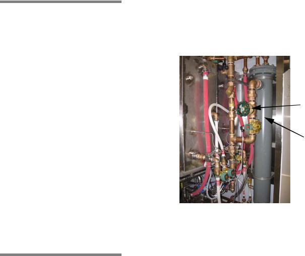
3.9 Heat Exchanger
3.10 Automatic
Detergent Injection
System
Washer is equipped with a steam heat exchanger and valving system to preheat incoming fill water, reducing normal water/solution heat-up time (see Figure 3-10).
System is fully automatic and works during filling function of Prewash, optional Acid Wash (if acid tank is not available), and Rinse phases. Heat exchanger steam valve is energized only if temperature is below 165°F (73.8°C).
Heat
Exchanger
Heat
Exchanger
Steam
Throtling
Valve
Figure 3-10. Heat Exchanger
Automatic Detergent Injection System includes a peristaltic pump mounted to washer exterior. System also includes a conductivity probe located in chamber sump.
If using alkaline detergent with injection system, alkaline detergent is automatically injected into chamber sump during Wash phase of a cycle.
•Hot detergent solution from alkaline detergent tank fills sump until required solution level is attained. Once sump is full, control checks detergent concentration of solution in sump. Alkaline detergent is then injected into sump until solution reaches set concentration level. Alkaline detergent solution is monitored and maintained at set concentration level while recirculating and spraying over load.
If using acid detergent with injection system, acid detergent is automatically injected into chamber sump during Acid Wash phase of a cycle.
•Hot detergent solution from acid detergent tank fills sump until required solution level is attained. Once sump is full, control checks detergent concentration of solution in sump. Acid detergent is then injected into sump until solution reaches set concentration level. Acid detergent solution is monitored and maintained at set concentration level while recirculating and spraying over load.
3-9
Component Identification |
Operator Manual |
122997-341 |
3.11 Reusable-
Throwaway Acid
Detergent System
Washers equipped with Reusable-Throwaway Acid Detergent System can be programmed to process an Acid Wash phase after Detergent Wash phase, and to either save or drain acid detergent solution on completion of phase.
System includes a separate acid detergent tank and piping constructed of stainless steel. Acid detergent tank is equipped with a steam coil to maintain acid detergent solution at programmed temperature.
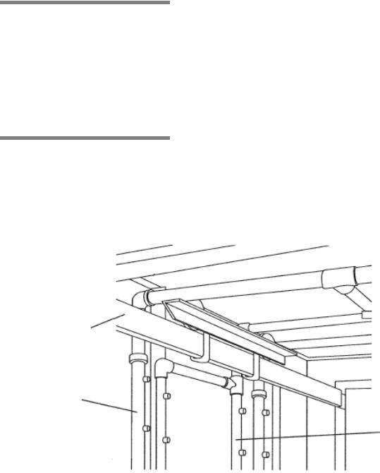
3.12 NonRecirculated
Final Rinse
Washers equipped with Non-Recirculated Final Rinse System can be programmed to spray load with fresh, non-recirculated water during standard Final Rinse phase. System includes a separate spray header mounted directly to each side of oscillating carriage, inside of main spray headers (see Figure 3-11).
Carriage Rail
Main Spray Header
Separate Spray Header
for Fresh Water
Figure 3-11. Non-Recirculated Final Rinse Spray Header
3-10
122997-341 |
Operator Manual |
Component Identification |

3.13 Feeder Bottle
Washing System
3.14 Automatic Water
Flush System for Two
Racks
Feeder Bottle Washing System provides capability of processing a loaded bottle cart during normal cycle operation. System includes a quick disconnect coupler.
NOTE: Bottle washing cart is available as a separate accessory.
Cycle must be programmed to process bottle cart before starting cycle operation.
Automatic Water Flush System for two racks permits cleaning of facility’s automatic watering system during normal cycle operation. System includes a set of two hoses, each equipped with a quick disconnect fitting, mounted on service side carriage rail.
Hoses are manually connected to customer cage watering racks moved into wash chamber. During Final Rinse filling, fresh hot water is sent through heat exchanger and sprayed over cage watering racks for programmed filling time interval.
3-11
Component Identification |
Operator Manual |
122997-341 |
3.15 Drain Discharge
Cooldown with Side
Tank and Temperature
Guarantee
A separate tank is typically mounted along service side of washer to temporarily retain and cool all drain discharges (see Figure 3-12).
NOTE: Location of drain discharge side tank may change depending on other options ordered with washer.
During draining function of each phase, solution/water in sump is automatically pumped to side tank where cold tap water is added. Cold water remains on until water temperature in side tank reaches programmed set point. Once cooled to set temperature, side tank gravity drains to building drain system.
Drain Discharge Side
Tank
Figure 3-12. Drain Discharge Side Tank (Typical)
3-12
122997-341 |
Operator Manual |
Component Identification |
3.16 Drain Discharge Cooldown System with Cold Water Injection Only
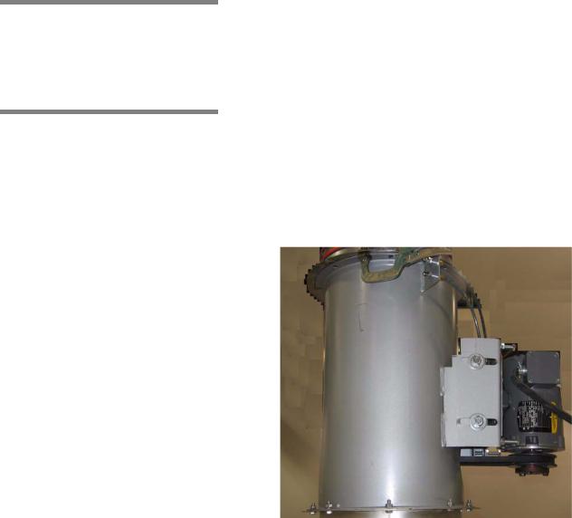
3.17 Exhaust Fan
Washer drain system is piped to automatically cool all drain discharges using building cold water supply.
During draining function of each phase, cold tap water is injected into washer drain line as washer drain discharges are sent directly to building drain system. Cold water remains on until sump drain valve closes.
Exhaust Fan is mounted directly in washer exhaust line, on top of unit
(see Figure 3-13).
During unit operation, exhaust fan removes residual vapors from wash chamber and directs vapors to building exhaust duct.
Figure 3-13. Exhaust Fan
3-13
Component Identification |
Operator Manual |
122997-341 |
WASHER OPERATION |
4 |
|
|
|
|
|
|
|
IMPORTANT: A listing of the Safety Precautions to be observed when operating and servicing this Cage and Rack Washer can be found in SECTION 1. Do not install equipment until you have become familiar with this information.
4.1 Before Operating
Washer
WARNING – CHEMICAL BURN AND/OR EYE INJURY HAZARD: Washer chemicals are caustic and can cause adverse effects to exposed tissues. Do not get in eyes, on skin or attempt to swallow. Read and follow precautions and instructions on chemical label and in Material Safety Data Sheet (MSDS) prior to handling detergent containers, or servicing detergent injection pumps, tank, and lines. Wear appropriate Personal Protective Equipment (PPE) whenever handling chemicals or servicing chemical injection pumps, tank, and lines.
CAUTION – POSSIBLE EQUIPMENT DAMAGE:
•Always use non-foaming chemical for effective cleaning and proper pump and water level control operation. Follow manufacturer’s recommendations for amount of chemical to be used.
•When choosing a detergent, select one with a low chloride content. Detergents with a high chloride content can corrode stainless steel.
Become familiar with location and function of all major components
and controls, as well as their function before operating equipment.
1.Verify building electrical supply disconnect switch (circuit breaker) is positioned to ON. Verify steam and water supply valves are open.
2.Open chamber door. Verify chamber is empty and all material has been removed.
3.Verify debris screens in bottom of sump are clean and properly installed.
4.Open printer door and check sufficient amount of printer paper is available.
NOTE: A colored warning stripe is visible when printer paper roll is near the end. Refer to SECTION 6.7, PRINTER PAPER, if paper is needed.
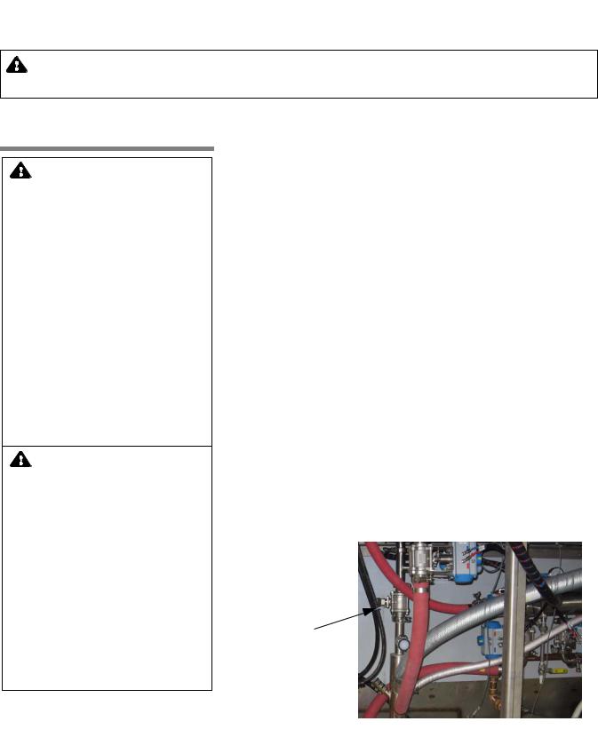
5.Ensure manual drain valves on bottom of detergent tanks and, if applicable, optional acid detergent tank are closed (see Figure 4-1).
6.Verify detergent supply (provided by customer). Check sufficient
amount of detergent is available (Refer toSECTION 6.6.5, REPLAC- ING DETERGENT CONTAINER). Ensure supply hose(s) is correctly placed in detergent container(s) and detergent pump(s) is turned on.
NOTE: Always use a non-foaming detergent for effective cleaning and proper pump and water level control operation. To achieve maximum cleaning efficiency, select detergent appropriate to soil type being processed.
Manual Drain
Valve
Figure 4-1. Manual Drain Valve
4-1
Washer Operation |
Operator Manual |
122997-341 |

4.2 How to Load Washer
WARNING – PERSONAL INJURY HAZARD:
•Keep fingers away from door hinges to prevent pinching.
•To prevent tipping, place biggest and heaviest items on the lower levels of accessory cart.
WARNING – BURN HAZARD: When cycle is complete, partially open chamber door and allow chamber and load to cool. Hot steam may escape through door opening if door is fully opened after a cycle.
WARNING – SLIPPING HAZARD: To avoid slippery floor conditions, keep floor dry. Promptly wipe up any spilled liquids or condensation. If spilled liquids are detergents or other chemicals, follow safety precautions and handling procedures set forth on detergent or chemical label and/or Material Safety Data Sheet (MSDS).
CAUTION – POSSIBLE EQUIPMENT DAMAGE:
•Avoid product damage. Always select a cycle appropriate for items being processed.
•Before operating unit, always position manifolded Bottle Washing Cart over central water inlet connector. If manifolded accessory is not positioned correctly, damage may result and unit will be unable to effectively wash load.
•Do not process load using Bottle Washing Cart when Automatic Floor Tilting option is activated. If Automatic Floor Tilting is used, manifolded water inlet and washer will be damaged.
4-2
To properly clean items and avoid personal injuries, always follow these general guidelines:
1.Remove gross soil before processing in washer.
2.Use appropriate accessory racks within cart to load items such as bottles.
3.Assure no items stick out or hang out of the accessory cart.
4.Place biggest and heaviest items on the lower levels of accessory cart.
5.As an example, proper placement of items in Washing Cart would be as follows, from the top down
Accessories (see Figure 4-2):
•Bottle Washing Cart – Used for processing up to six bottle baskets. Requires Manifold Coupling System.
•Pan Cart – Used to wash pans, floor gratings, cage doors, etc.
•Universal Cage and Wash Cart – Used to wash 54 standard mouse boxes or 36 standard rat boxes.
•Rodent Cage Rack – Used to hold up to 92 mouse cages or 32 rat cages, or shoe boxes, covers, and feeder tops.
IMPORTANT: Use baskets for handling and cleaning various size bottles. Lightweight basket design provides easy handling and simplifies transport and washing of bottles.
•5 x 5 Bottle Basket – Used to wash 25,16 oz (454 mL) bottles.
•4 x 6 Bottle Basket – Used to wash 24, 16 oz (454 mL) bottles.
•5 x 5 Bottle Basket – Used to wash 25 short 4" (10 cm) bottles.
•4 x 6 Bottle Basket – Used to wash 24 tall 5-1/2" (14 cm) bottles.
6.Open chamber door and push loaded wash cart(s) into wash chamber.
a.Ensure all cages, racks, etc. are correctly positioned on wash cart(s).
b.Position cart(s) in center of wash chamber. Verify clearance space on both sides of cart permits unobstructed movement of oscillating jet system.
7.Close and latch chamber doors securely.
NOTE: Door safety switch prevents cycle operation unless door(s) is closed.
8.Start desired cycle.
CAUTION – POSSIBLE EQUIPMENT DAMAGE: Remove all cellulose-type bedding from cages and pans before processing. Cellulose bedding can clog filters and piping.
122997-341 |
Operator Manual |
Washer Operation |
Loading...