


 Loading...
UNCRATING/INSTALLATION INSTRUCTIONS
Basil® 4600 Cage and Rack Washer
Basil® 4602 Cage and Rack Washer
(2004-02-13) |
P910000-015 |

A WORD FROM STERIS CORPORATION
Follow each step of these Uncrating/Installation Instructions in the order presented. To avoid damage to the equipment inside, open the carton carefully. If you find any indication of damage to the equipment (no matter how slight), show it to your supervisor.
To properly install this unit, you will need the Equipment Drawings provided, showing all utility service and space requirements. If drawings cannot be located, replacement copies may be obtained by writing, faxing, or telephoning STERIS, giving the serial number and model of your unit.
Once installed, unit operation should be tested by a STERIS-trained service technician prior to your equipment usage.
If STERIS supervision is desired for installing and starting up this equipment, contact STERIS for pricing and availability of this service in you region.
IMPORTANT: This unit is specifically designed to only process goods as Advisory outlined in Operator Manual (P122997-341).
A listing of the Safety Precautions to be observed when uncrating, installing, and testing this equipment can be found in Section 1 of this manual. Do not begin uncrating/installing the equipment until you have become familiar with this information.
Any alteration of this equipment not authorized or performed by STERIS which could affect equipment operation will void the warranty, could adversely affect cleaning efficacy, could violate national, state, and local regulations, and could jeopardize your insurance coverage.
To assure operators are adequately trained in the safe use of the equipment,
STERIS recommends that:
•all personnel who operate or maintain the equipment are trained in its operation and in its safe use;
•personnel working with toxic chemicals and vapors (if applicable) have comprehensive instructions in the unit, process, relevant health hazards, and methods to detect the escape of toxic materials;
•there is regular training of all personnel concerned with the operation and maintenance of the equipment; attendance records are maintained; and the evidence of understanding is demonstrated.
©2004, STERIS Corporation. All rights reserved. |
Printed in Canada |
i
Table of Contents |
Uncrating/Installation Instructions |
910000-015 |

Indications for Use
Service Information
The Basil® 4600 Cage and Rack Washer and Basil® 4602 Cage and Rack Washer are heavy duty, large capacity hydrospray washers designed for thorough, efficient cleaning of cages, racks, debris pans and miscellaneous items used in the care of laboratory animals.
These units are specifically designed to only process goods as outlined in the Operator Manual. If there is any doubt about a specific material or product, contact the manufacturer of the product for the recommended washing technique.
A thorough preventive maintenance program is essential to safe and proper unit operation. You are encouraged to contact STERIS concerning our comprehensive Annual Maintenance Agreements. Under the terms of these agreements, preventive maintenance, adjustments, and replacement of worn parts are done on a scheduled basis to help assure equipment performance at peak capability and to help avoid untimely or costly interruptions. STERIS maintains a global staff of well equipped, factory-trained technicians to provide this service, as well as expert repair services. Please contact STERIS for details.
For contact information, see inside back cover.
The Basil 4600 Cage and Rack Washer and Basil 4602 Cage and Rack
Certification Washer meet the applicable requirements of the following standards:
•Underwriters Laboratories (UL) Standard 1262, as certified by ITS Testing Laboratories, Inc.
ii
910000-015 |
Uncrating/Installation Instructions |
Table of Contents |

TABLE OF CONTENTS
Section Title Page
A WORD FROM STERIS CORPORATION ............................................ |
i |
Advisory ................................................................................................................................. |
i |
Indications for Use ................................................................................................................. |
ii |
Service Information ................................................................................................................ |
ii |
Certification ............................................................................................................................ |
ii |
1 |
LISTING OF SAFETY PRECAUTIONS............................................. |
1-1 |
|
|
Definition of Symbols ......................................................................................................... |
1-2 |
|
2 |
INSTALLATION REQUIREMENTS ................................................... |
2-1 |
|
3 |
ASSEMBLY INSTRUCTIONS ........................................................... |
3-1 |
|
|
3.1 |
General Guidelines ...................................................................................................... |
3-1 |
|
3.2 |
Base ........................................................................................................................... |
3-1 |
|
3.3 |
Cabinet ...................................................................................................................... |
3-4 |
|
3.4 |
Chamber (Inner Cabinet) ............................................................................................ |
3-11 |
|
3.5 |
Service Side of Cabinet.............................................................................................. |
3-15 |
|
3.6 |
Top of Cabinet ............................................................................................................ |
3-19 |
|
3.7 |
Final Assembly/Clean-up ........................................................................................... |
3-20 |
4 |
INSTALLATION CHECKLIST .......................................................... |
4-1 |
|
5 |
OPERATIONAL CHECKLIST ........................................................... |
5-1 |
|
iii
Table of Contents |
Uncrating/Installation Instructions |
910000-015 |

LISTING OF SAFETY PRECAUTIONS |
|
1 |
|
|
|
The following listing of Safety Precautions must be observed when installing this equipment. WARNINGS indicate the potential for danger to personnel, and CAUTIONS indicate the potential for damage to equipment. These Safety Precautions are repeated, where applicable, throughout the manual.
WARNING – PERSONAL INJURY HAZARD:
When handling cabinet panels, use extreme care and wear protective gloves. Panels are heavy and may have sharp edges.
When positioning cabinet panels two people are required to lift and support each panel because of weight and size. One person must support panel while the other person installs the nuts and bolts.
Before placing any weight on the roof panel, secure panel on top of cabinet by installing bolts and nuts, finger tight, in all four corners of roof panel.
When installing doors, more than one person is required to lift doors because of weight and size.
Wheninstallingcontrolcolumn(s),morethanonepersonisrequiredtoliftcontrolcolumninplacebecauseof weight and size.
When installing detergent tank, more than one person is required to lift tank because of weight and size.
When moving sump coil, more than one person is required to lift coil because of weight and size.
CAUTION – POSSIBLE EQUIPMENT DAMAGE:
When checking rotation of drive motor, use extreme caution. If rotation is incorrect, carriage will run directly into the door header.
1-1
Listing of Safety Precautions |
Uncrating/Installation Instructions |
P910000-015 |

Definition of |
Symbol |
Definition |
Symbols |
|
|
|
|
Protective Earth (Ground) |
Warning! Risk of Electrical Shock
1-2
P910000-015 |
Uncrating/Installation Instructions |
Listing of Safety Precautions |
INSTALLATION REQUIREMENTS |
|
2 |
|
|
|
NOTE: Please review these instructions carefully prior to installing equipment.
Follow instructions in the sequence given.
1.Review installation site and room layout drawings provided with Installation Kit. It may be necessary to vary the actual installation from the drawings due to space limitations or existing obstructions.
2.If necessary, unload, uncrate and move equipment to installation site. Refer to Uncrating / Utility Connection Instructions (P910000-016) shipped with unit.
3.If handling disposal of debris, ensure customer signs off on the disposition of trash left on the job site.
4.Check the Occupational Health and Safety Act as well as local electrical and plumbing codes for any special requirements that may pertain to the installation of this equipment.
5.Recommend to customer that shutoff valves be installed at readily accessible locations in steam and water supply lines near the equipment.
6.Recommend to customer that disconnect switch (with OFF position lockout only) be installed in electric supply line within 10 feet of the equipment.
NOTE: If washer is installed next to other equipment, shutoff valves and disconnect switch must be placed so that service can be shut off to any one piece of equipment at a time.
2-1
Installation Requirements |
Uncrating/Installation Instructions |
P910000-015 |

INSTALLATION INSTRUCTIONS |
|
3 |
|
|
|
1.All mounting hardware necessary for complete installation is shipped with
3.1General the unit. Not every piece of mounting hardware will be utilized; ample
Guidelines
amounts are provided.
2.If necessary, use 6'' X 6'' X 1/8'' thick stainless-steel shims to level equipment. Do not exceed 3/4-inch shim height. If equipment requires more than 3/4" shimming material, use square tubing to level equipment.
3.Use silicone (RTV) provided in Installation Kit to seal all panel joints to assure water tightness. When caulking, silicone bead should be a minimum of 1/4 inch wide and completely circle all bolt holes. When in doubt, use silicone liberally. It is easier to prevent a leak during assembly than to fix a leak once equipment is in use.
4.All bolts going to atmosphere (from inside of chamber to outside of cabinet) require sealing washers.
5.All bolts require lockwashers, except the welded nuts along the non-service side of the washer.
|
1. |
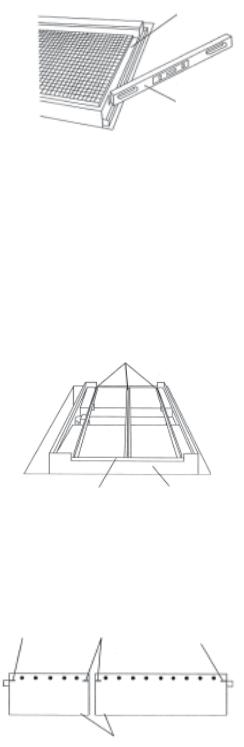
Lift door grating and remove sump coil from base. Replace floor grating in |
3.2 Base |
base. |
|
2.Position base according to room layout drawings, either in a pit or on the floor. It pit mounted, make sure face of surface is parallel to pit wall (within two to thee inches from the non-service side wall) or positioned as specified in the room layout drawings.
3.Check base height (see Figure 3-1). Ensure the door threshold is at least 1/4" higher than the highest spot on the floor, along the netire door swing (four feet from base). If necessary, position shims under corners of base.
Four Feet
Door Swing
1/4"
Add shims here, if necessary, to achieve proper height and level
Base |
Door Threshold |
|
1/4"
Pit Pad
Figure 3-1. Check Base Height
3-1
Installation Instructions |
Uncrating/Installation Instructions |
920000-015 |
If pit mounted, use a four-foot level to check the door swing (see Figure 3-2). Hold one end of level on door threshold and place two 1/8-inch shims under the opposite end. Check door swing at 90°, 45°, and 15°.
NOTE: When shimming, ensure shim is placed under corner of base with part of the shim exposed.
Door Threshold
Foor-Foot Level
Figure 3-2. Check Door Swing
4.Check level of base along face and length. If necessary, position shims under corners of base. If shims are used to level base, base height must be re-checked once the base is level.
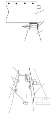
5.In some instances, the base may be shipped in two or three pieces. If base is split, assemble base pieces as follow:
a.Position base pieces, next to one another, close to the final location indicated on the room layout drawings.
b.Connect the base pieces by installing the floor grating supports down the center of the base and on either side of the door threshold (see Figure 3-3).
Floor Grating Supports
Door Threshold |
Base |
Figure 3-3. Install Floor
c.Align the base pieces by stretching a string across the four alignment marks located on the side of each piece (see Figure 3-4). If necessary, position shims under corners of base piece(s).
Alignment |
Alignment |
Alignment |
|
Mark |
Mark |
||
Mark |
|||
|
|
Base Pieces
Figure 3-4. Align Base Pieces
3-2
910000-015 |
Uncrating/Installation Instructions |
Installation Instructions |
d.Check base height and level of base as explained in Steps 3 and 4.
e.Once base is level, spot weld a series of one-inch welds along the base seams to maintain the established position.
NOTE: The heat generated by most welding operations will damage epoxy/vinyl flooring. Take appropriate precautions to protect floor from heat and welding arc.
f.Completely weld all base pieces together from the inside.
g.Check for pin holes and incomplete welds. All welds must be water tight.
h.Clean up welds using a wire brush.
6.If shims were used, weld shims in place to form a solid foundation (see Figure 3-5).
Base
Weld
Shims
Pit Pad
Figure 3-5. Weld Shims
7.Attach pump plate to service side of washer (see Figure 3-6). Ensure brackets are facing up and plate does not cover drain hole.
Pump
Plate
Brackets
(Facing Up)
Service Side
of Washer
Drain Hole
Figure 3-6. Install Pump Plate
8.Check level of pump plate along the plate width and length. If necessary, position shims under the brackets attached to pump plate. Silicone shims in place, using a heavy bead of silicone between the shims, between the pump plate and shims and between the shims and floor.
If pit mounted, ensure shims are flush with the pit wall.
9.Re-tap threads on all welded nuts (along the non-service side of the washer) with 5/16''-18 threads/inch tap.
3-3
Installation Instructions |
Uncrating/Installation Instructions |
920000-015 |

3.3 Cabinet
WARNING–PERSONAL INJURY HAZARD:
•Whenhandlingcabinetpanels, use extreme care and wearprotectivegloves.Panels are heavy and may have sharp edges.
•When positioning cabinet panels, two people are required to lift and support each panel because of weight and size. One person must support the panel while the other installs the nut and bolts.
NOTE: Cabinet must be completely assembled and tightened within the same day, before silicone hardens.
1.Remove paper from all cabinet panels.
2.Select any corner panel to begin cabinet assembly.
3.Count the number of bolts holes along side of corner panel (e.g. six bolt holes).Donotcountboltholesalongface(load/unloadside)ofcornerpanel.
NOTE: When caulking, fully open caulk nozzle to allow for a heavy silicone bead.
4.On inside of base, silicone around and between the number of bolt holes counted plus one (e.g. seven bolt holes; see Figure 3-7). Do not silicone along face of unit. Make sure to silicone in a consistent line.
NOTE: Only silicone around and between the base bolt holes needed to install one panel at a time.
DO NOT Silicone Silicone Bolt Holes
Face of Cabinet
Figure 3-7. Silicone Around and Between Bolt Holes
5.Position bottom of corner panel on base lip. Using your foot, hold bottom of panel on the lip and raise panel up into place. Insert alignment pins, one on either end, to align panel and base bolt holes (see Figure 3-8).
NOTE: All bolts going to atmosphere (from inside of chamber to outside of cabinet) require sealing washers. All bolts require lockwashers, except the welded nut along the non-service side of the washer.
Alignment
Pin Corner
Panel
Alignment
Pin
Base Lip
Figure 3-8. Insert Alignment Pins
3-4
910000-015 |
Uncrating/Installation Instructions |
Installation Instructions |
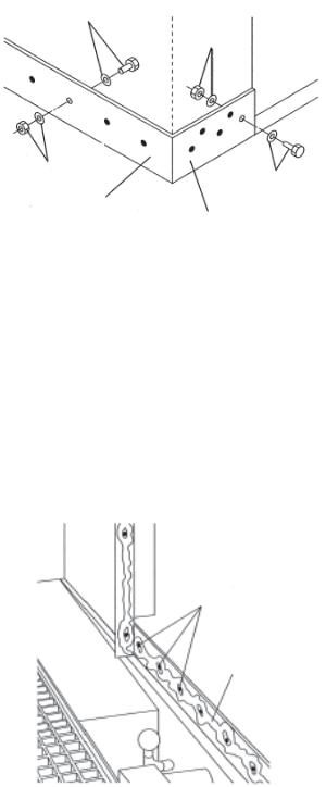
6.Attach panel to base. Ensure bolts along face of base are installed with the bolt heads located on outside of base, and bolts along side of base are installed with the bolt heads located on inside of base (see Figure 3-9).
NOTE: During panel assembly, all bolts are installed snug (tight enough to flatten the silicone). Once cabinet is completely assembled, bolts will be securely tightened.
Bolt and Sealing
Washer
Nut and
Lockwasher
Nut and
Lockwasher Bolt and Sealing
Washer
Side of Base
Face of Base
Figure 3-9. Bolt Positions for Corner Panel
7.Locate next panel to be installed. Each panel is numbered and installed in sequential order, starting with the number assigned to the first corner panel installed.
8.Count the number of bolt holes along bottom of panel.
9.Starting from top of installed panel, silicone around and between bolt holes along the vertical panel joint and along inside of base (see Figure 3-10). When caulking base, ensure to silicone around the number of bolt holes counted plus one.
NOTE: Critical Leak areas are at the top and bottom of vertical panel joints, and along base seams if base was split. Use silicone liberally in these areas.
Bolt Holes
Silicone
Figure 3-10. Silicone Vertical Panel Joint and Base
3-5
Installation Instructions |
Uncrating/Installation Instructions |
920000-015 |
Loading...