


 Loading...
UNCRATING/INSTALLATION INSTRUCTIONS
BASIL® 9500 Cage and Rack Washer
(05/23/02) |
P-122998-049 |
Rev. 4 |
|
LIMITATIONS OF LIABILITY AND INDEMNITY
IN NO CASE, WHETHER AS A RESULT OF A BREACH OF CONTRACT, BREACH OF WARRANTY, OR TORT (INCLUDING STERIS’S OR CUSTOMER’S WILLFUL ACTS, NEGLIGENCE, OR STRICT LIABILITY) SHALL STERIS OR CUSTOMER BE LIABLE TO THE OTHER FOR ANY CONSEQUENTIAL OR INCIDENTAL DAMAGES INCURRED BY THE OTHER, INCLUDING, BUT NOT LIMITED TO, LOSS OF REVENUE, PROFITS, OR GOODWILL. HOWEVER, NOTHING CONTAINED IN THIS MANUAL IS INTENDED TO RELIEVE EITHER STERIS OR CUSTOMER FROM CLAIMS, LIABILITY, DAMAGES, OR EXPENSES RESULTING FROM BODILY INJURY, INCLUDING DEATH, OR FROM PROPERTY DAMAGE INCURRED DUE TO THE WILLFUL ACTS, NEGLIGENCE, OR STRICT LIABILITY OF THAT PARTY.
STERIS AGREES TO DEFEND, INDEMNIFY, AND HOLD CUSTOMER HARMLESS FROM ANY AND ALL CLAIMS, LIABILITY, DAMAGES, OR EXPENSES DUE TO PERSONAL INJURIES, INCLUDING DEATH, TO EMPLOYEES OF STERIS AND CUSTOMER AND TO THIRD PARTIES AND FOR PROPERTY DAMAGE TO THE EXTENT CAUSED BY THE WILLFUL ACTS, NEGLIGENCE, OR STRICT LIABILITY OF STERIS . CUSTOMER AGREES TO DEFEND, INDEMNIFY, AND HOLD STERIS HARMLESS FROM ANY AND ALL CLAIMS, LIABILITY, DAMAGES, OR EXPENSES DUE TO PERSONAL INJURIES, INCLUDING DEATH, TO EMPLOYEES OF CUSTOMER AND STERIS AND TO THIRD PARTIES AND FOR PROPERTY DAMAGE TO THE EXTENT CAUSED BY THE WILLFUL ACTS, NEGLIGENCE, OR STRICT LIABILITY OF CUSTOMER.
WARNING - COPYING PROHIBITED
This manual is protected by Federal Copyright Law, which provides for damages of up to USD $20000, as well as criminal fines and imprisonment, for unauthorized copying.

A WORD FROM STERIS CORPORATION
Indications for Use
Advisory
Followeachstepoftheuncrating/installationinstructionsin the order presented. Toavoid equipment damage, carefully open the carton. If you find any indication equipment damage (no matter how slight), showit to your supervisor.
To properly install this unit, you will need the Equipment Drawings (previously furnished), showing all utility service and space requirements. If drawings cannot be located, replacement copies may be obtained by writing, faxing or telephoning STERIS giving the serial and model numbers of your equipment.
Once installed, equipment operation should be tested by a qualified service technician (as outlined in Section 5) prior to equipment usage.
If STERIS supervision is desired, for installing and starting up this equipment, contact your local STERIS representative.
The Basil® 9500 Cage and Rack Washer is intended for use in the sanitation of soiled, reusable animal care devices (such as cages, racks, debris pans, feeder bottles) and other miscellaneous items by providing thorough cleaning and optimal drying. Safety hazards may occur if unit is used for other purposes than stated above.
A listing of safety precautions to be observed when uncrating, installing, and testing this equipment can be found in Section 1 of these instructions. Do not begin uncrating/installing this equipment until you have become familiar with this information.
AnyalterationofthewashernotauthorizedorperformedbySTERISEngineering Service which could affect its operation will void the warranty, could adversely affect washing efficacy, could violate national, state and local regulations, and could jeopardize your insurance coverage.
IMPORTANT: Check local occupational health and safety regulations, as well as electric and plumbing codes, for any special requirements that may pertain to installation of this unit.
©2002 , STERIS Corporation. All rights reserved. |
Printed in Canada. |
i
Table of Contents |
Uncrating/Installation Instructions |
122998-049 |

A thorough preventive maintenance program is essential to safe and proper Service Information equipment operation. You are encouraged to contact your STERIS representativeconcerningextendedservicemaintenanceagreementstogiveyourwasher planned maintenance, assuring equipment performance according to factory specifications. A global network of skilled service specialists can provide periodic inspections and adjustments to assure low-cost peak performance.
STERIS representatives can provide information regarding Annual Maintenance Agreements.
STERIS carries a complete line of accessories for use in this equipment. A
STERIS representative will gladly review these with you.
See inside back cover for contact information.
This Basil 9500 Cage and Rack Washer complies with the following standards:
Certification • American and Canadian Standards:
Conform to ANSI/UL Std. 3101-1 conform to CAN/CSA Std. C22.2 1010.1
• Governing Directive for the Affixing of the CE Mark:
Machinery Directive (98/37/CE).
• Conformity to Other Applicable Directives:
Electromagnetic Compatibility Directive (89/336/EEC) and amendments (92/31/EEC, 93/68/EEC); Low VoltageDirective(73/23/EED) and amendment (93/68/EC).
•Standards applied to demonstrate conformity to the directives:
IEC 1010-1 (1990); A1 (1992) A2 (1995); EN 50081-2; EN 55011; CISPR 11; EN 50082-2; EN 61000-4-2; EN 61000-4-3/ENV 50140; ENV 50204; EN 61000-4-4; EN 61000-4-6/ENV 50141.
ii
122998-049 |
Uncrating/Installation Instructions |
Table of Contents |

TABLE OF CONTENTS
Section Title Page
1 LISTING OF WARNINGS, CAUTIONS, AND SYMBOLS .................. |
1-1 |
|
|
1.1 Symbols ....................................................................................................................... |
1-4 |
2 |
SITE PREPARATION ......................................................................... |
2-1 |
|
2.1 Before Installing Equipment ......................................................................................... |
2-1 |
3 |
UNCRATING/INSTALLATION INSTRUCTIONS ................................. |
3-1 |
|
3.1 Open Crates ................................................................................................................ |
3-1 |
|
3.1.1 Assembled Unit ................................................................................................... |
3-1 |
|
3.1.2 Disassembled Unit .............................................................................................. |
3-5 |
|
3.2 Disassembled Unit Assembly ...................................................................................... |
3-7 |
|
3.2.1 Crate A ................................................................................................................ |
3-7 |
|
3.2.2 Sump ................................................................................................................... |
3-7 |
|
3.2.3 Non-Service Side Walls ....................................................................................... |
3-9 |
|
3.2.4 Service Side Panels ........................................................................................... |
3-11 |
|
3.2.5 Control Configuration ......................................................................................... |
3-11 |
|
3.2.6 Temporary Roof Support ................................................................................... |
3-13 |
|
3.2.7 Roof ................................................................................................................... |
3-15 |
|
3.2.8 Crate B .............................................................................................................. |
3-17 |
|
3.2.9 Roof End ............................................................................................................ |
3-19 |
|
3.2.10 Door Rail Holders ............................................................................................ |
3-21 |
|
3.2.12 Roof Components ............................................................................................ |
3-23 |
|
3.2.13 Single-Door Washer Back Panel Installation (option) ...................................... |
3-25 |
|
3.2.14 Emergency Guard Rails .................................................................................. |
3-27 |
|
3.2.15 Spray Headers ................................................................................................ |
3-29 |
|
3.2.16 Cabinet Corners .............................................................................................. |
3-31 |
|
3.2.17 Control Panel Adjustment ................................................................................ |
3-31 |
|
3.2.18 Door Frames .................................................................................................... |
3-33 |
|
3.2.19 Roller Stoppers ................................................................................................ |
3-35 |
|
3.2.20 Door Panels ..................................................................................................... |
3-37 |
|
3.2.21 Ventilation Duct ................................................................................................ |
3-39 |
|
3.2.22 Pulley Guards ................................................................................................... |
3-41 |
|
3.2.23 Traveler Driver Cable ........................................................................................ |
3-43 |
|
3.2.24 Traveler Safety Cable ....................................................................................... |
3-45 |
|
3.2.25 Crate C ............................................................................................................. |
3-47 |
|
3.3 Move and Remove Skid ............................................................................................. |
3-47 |
|
3.3.1 Mobile Mechanical Core....................................................................................... |
3-47 |
|
3.3.2 Mechanical Core ................................................................................................. |
3-51 |
|
3.3.3 Flexible Utility Hoses and Quick-Disconnect System (Option) ............................ |
3-53 |
|
3.3.4 Leveling Legs (Accessory) .................................................................................. |
3-53 |
|
3.3.5 Crate D ............................................................................................................... |
3-55 |
|
3.3.6 Drying Option Disassembled Units ..................................................................... |
3-55 |
|
3.3.7 Pneumatic Connections ....................................................................................... |
3-57 |
iii
Table of Contents |
Uncrating/Installation Instructions |
122998-049 |

TABLE OF CONTENTS (CONT'D)
Section |
Title |
Page |
|
|
3.3.8 Door Links ............................................................................................................ |
3-61 |
|
|
3.3.9 Electrical Connections ......................................................................................... |
3-63 |
|
|
3.4 Connect Utilities .......................................................................................................... |
3-67 |
|
|
3.5 Service Panels............................................................................................................. |
3-69 |
|
|
3.6 Ramp (Accessory) (All Units) ...................................................................................... |
3-71 |
|
|
3.7 Service Access Panels ............................................................................................... |
3-73 |
|
|
3.8 Move and Remove Skid .............................................................................................. |
3-75 |
|
4 |
INSTALLATION CHECKLIST ............................................................ |
4-1 |
|
5 |
START-UP TEST ............................................................................... |
5-1 |
|
|
5.1 Installation of pH Probe ............................................................................................... |
5-2 |
|
|
5.2 How to Enter Factory Set-Up Mode ............................................................................. |
5-3 |
|
|
5.2.1 |
How to Verify Indicator Lights .............................................................................. |
5-5 |
|
5.2.2 How to Verify Door Configuration ........................................................................ |
5-6 |
|
|
5.3 How to Enter Service Mode ....................................................................................... |
5-10 |
|
|
5.3.1 |
How to Activate Digital Outputs ........................................................................ |
5-11 |
|
5.3.2 How to Verify Suction Pump Rotation (Option) .................................................. |
5-12 |
|
|
5.3.3 |
How to Verify Drying Fan Rotation (Option) ...................................................... |
5-13 |
|
5.3.4 |
Air/Oil Tanks....................................................................................................... |
5-15 |
|
5.4 Calibration ................................................................................................................. |
5-17 |
|
|
5.4.1 How to Calibrate Chemical Injection Rate ......................................................... |
5-17 |
|
|
5.4.2 How to Set Descaler Rate ................................................................................. |
5-20 |
|
|
5.5 How to Set pH Ratios ................................................................................................. |
5-21 |
|
|
5.5.1 STERIS Chemicals .............................................................................................. |
5-21 |
|
|
5.5.2 Non-STERIS Chemicals ........................................................................................ |
5-24 |
|
|
5.5.3 How to Calibrate Chemical Neutralizing (pH) System (Option) ........................... |
5-25 |
|
|
5.6 Miscellaneous Verifications in Automatic Mode .......................................................... |
5-29 |
|
|
5.6.1 Safety Features ................................................................................................... |
5-29 |
|
|
5.6.2 Automatic Floor Tilt (Option) ............................................................................... |
5-31 |
|
|
5.6.3 Piping and Ventilation ......................................................................................... |
5-31 |
|
|
5.6.4 Manifold Coupling System (Option) .................................................................... |
5-32 |
|
|
5.6.5 Clean Steam Supply Valve .................................................................................. |
5-32 |
|
iv
122998-049 |
Uncrating/Installation Instructions |
Table of Contents |

TABLE OF ILLUSTRATIONS
FIGURE |
TITLE |
PAGE |
|
|
|
|
|
2-1. |
Utility Service Connections ............................................................................................................... |
|
2-1 |
3-1. |
Crates ............................................................................................................................................... |
|
2-2 |
3-2. |
Basil® 9500 Cage and Rack Washer, Reference View Point for All Installation Locations |
................. 3-4 |
|
3-3. |
Pit Mounted Unit ............................................................................................................................... |
|
3-6 |
3-4. |
Non-Service Side Walls .................................................................................................................... |
|
3-8 |
3-5. |
Service Side Panels ........................................................................................................................ |
|
3-10 |
3-6. |
Temporary Roof Support .................................................................................................................. |
|
3-12 |
3-7. |
Roof ................................................................................................................................................. |
|
3-14 |
3-8. |
Roof End .......................................................................................................................................... |
|
3-18 |
3-9. |
Door Rail Holders ............................................................................................................................. |
|
3-20 |
3-10. |
Roof Components ............................................................................................................................ |
|
3-22 |
3-11. |
Single-Door Washer Back Panel (Option) ......................................................................................... |
|
3-24 |
3-12. |
Crate D: Inside Chamber Components ............................................................................................. |
|
3-26 |
3-13.Spray Headers ................................................................................................................................... |
|
3-28 |
|
3-14. |
Cabinet Corners ............................................................................................................................... |
|
3-30 |
3-15. |
Door Frames .................................................................................................................................... |
|
3-32 |
3-16. |
Roller Stoppers ................................................................................................................................ |
|
3-34 |
3-17. |
Door Panels ..................................................................................................................................... |
|
3-36 |
3-18. |
Ventilation Duct ............................................................................................................................... |
|
3-38 |
3-19. |
Pulley Guards .................................................................................................................................. |
|
3-40 |
3-20. |
Traveler Cable.................................................................................................................................. |
|
3-42 |
3-21. |
Traveler Drive Cable ........................................................................................................................ |
|
3-44 |
3-22 |
Slide Mechanical Core ..................................................................................................................... |
|
3-46 |
3-23. |
Mobile Mechanical Core - Center of Gravity ..................................................................................... |
|
3-48 |
3-24. |
Mechanical Core Piping ................................................................................................................... |
|
3-49 |
3-25 |
pH Probe Location ........................................................................................................................... |
|
3-50 |
3-26 |
Flexible Utility Hoses ....................................................................................................................... |
|
3-52 |
3-27. |
Drying Option ................................................................................................................................... |
|
3-54 |
3-28. |
Bottom Pneumatic Connections ....................................................................................................... |
|
3-56 |
3-29. |
Top of Washer, Pneumatic Connections .......................................................................................... |
|
3-58 |
3-30. |
Door Links ....................................................................................................................................... |
|
3-60 |
3-31. |
Electrical Connections ..................................................................................................................... |
|
3-62 |
3-32. |
Supply Line Connections ................................................................................................................. |
|
3-66 |
v
Table of Contents |
Uncrating/Installation Instructions |
122998-049 |

TABLE OF ILLUSTRATIONS (CONT'D)
FIGURE |
TITLE |
PAGE |
|
|
|
|
|
3-33. |
Service Panels ................................................................................................................................ |
|
3-68 |
3-34. |
Ramp (Accessory) (All Units) ........................................................................................................... |
|
3-70 |
3-35. |
Service Access Panels .................................................................................................................... |
|
3-72 |
3-36. |
Service Access Panels (cont'd) ............................................................................................... |
.. |
.... 3-74 |
5-1. |
pH Probe ........................................................................................................................................... |
|
5-2 |
5-2. |
Control Panel and Printer .................................................................................................................. |
|
5-3 |
5-3. |
Typical Configuration Printout .......................................................................................................... |
|
5-14 |
5-4. |
Air/Oil Tanks .................................................................................................................................... |
|
5-13 |
5-5. |
Chemical Injection Port .................................................................................................................... |
|
5-16 |
5-6. |
Emergency Exit Safety Doors .......................................................................................................... |
|
5-28 |
5-7. |
Damper Adjustment ......................................................................................................................... |
|
5-33 |
LIST OF TABLES
TABLE |
TITLE |
PAGE |
|
5-1. |
I/O Board Outputs Test .................................................................................................................... |
|
5-7 |
5-2. |
I/O Board Inputs Test ....................................................................................................................... |
|
5-8 |
5-3. |
Control Board Analog Inputs Test ..................................................................................................... |
|
5-8 |
5-4 |
Interlock Features ............................................................................................................................. |
|
5-9 |
vi
122998-049 |
Uncrating/Installation Instructions |
Table of Contents |
LISTING OF WARNINGS, CAUTIONS, AND |
|
SYMBOLS |
1 |
The following is a listing of the safety precautions which must be observed when uncrating, installing and servicing this equipment. WARNINGS indicate the potential for danger to personnel, and CAUTIONS indicate the potential for damage to equipment. These precautions are repeated (in whole or in part), where applicable, throughout the manual.
WARNING – PERSONAL INJURY AND/OR EQUIPMENT DAMAGE HAZARD:
When moving the unit, use a forklift.
Only fully qualified service personnel should assemble and/or make adjustments to this equipment.
Assembly or adjustments done by inexperienced, unqualified personnel could cause personal injury or result in costly damage. Contact your STERIS sales or service representative regarding service options.
Do not remove protective paper covering from front of doors until door installation is complete. Paper secures exterior glass in place during transport and installation.
To test or demonstrate Emergency Exit Safety Doors, first press Emergency Stop Pushbutton (located under control) or Emergency Safety Guard Rails (inside wash chamber) to turn power OFF. If power is still on while adjusting or servicing doors, the Photoelectric Sensor will detect the movement of the door panels and doors will open automatically.
Do not assemble Drying System components (frame, fan and heat exchanger) prior to installation on the mechanical core. Lifting assembled Drying System may result in back injury or equipment damage.
WARNING – LACERATION/EYE INJURY HAZARD:
When removing bands, wear gloves and eye protection, and always use a tool specifically designed to cut the bands. The bands used to secure these crates can cause personal injury when cut and tension is released.
WARNING – LACERATION HAZARD:
When removing bolts, wear gloves to protect your hands.
WARNING – PERSONAL INJURY HAZARD:
Doors are heavy. Installation of doors requires two people.
When doors are closing a pinch point is created at the hinges. Keep fingers away from door hinges to prevent pinching.
Keep hands/fingers away from closing doors to prevent crushing between the two doors.
To open doors from inside wash chamber, press Emergency Safety Guard Rails. Washer operation will automatically stop. Then push firmly between door panels using shoulder and upper arm, applying upper body force. Do not push between the doors, but between door panels.
Two people are required to install the roof end sections. Using a step ladder, first set roof end on temporary roof end support brackets, then lift up and sit into position.
(See next page for additional warnings and cautions)
1-1
Listing of Warnings, Cautions, and Symbols |
Uncrating/Installation Instructions |
122998-049 |
WARNING – BURN HAZARD:
Except for emergency, do not open doors when cycle is in progress. In an emergency, first stop cycle by pressing the Emergency Stop pushbutton and wait for water flow to stop. Wear appropriate personal protective equipment (PPE) whenever reaching into or entering wash chamber.
Allow unit to cool down before performing any service on pump. Surface of motor and piping become very hot during unit operation.
Allow unit to cool down before performing any service on mechanical components and on piping. Components and piping become very hot during unit operation.
Allow piping to cool down before inspecting and/or cleaning supply line strainers.
When inspecting and/or cleaning supply line strainers, hot water/steam may be sprayed through door opening. Wear appropriate Personal Protective Equipment (PPE).
Inner surfaces of washer are very hot after cycle completion. Operator should wear appropriate Personal Protective Equipment (PPE) and avoid all contact with inner surfaces when entering wash chamber to unload washer.
WARNING – FALL HAZARD:
To prevent falls, keep floors dry. Promptly clean up any spills or drippage.
WARNING – ELECTRICAL SHOCK AND/OR BURN HAZARD:
Fasteners and star washers are used to ensure protective bonding continuity. Always reinstall any star washer which may have been removed during installation or servicing.
WARNING – CHEMICAL BURN/EYE INJURY HAZARD:
Washer chemicals are caustic and can cause adverse effects to exposed tissues. Do not get in eyes, on skin, or attempt to ingest by mouth.
•Read and follow the precautions and instructions on the chemical label and in the Material Safety Data Sheet (MSDS) prior to handling the chemical, refilling the chemical containers, or servicing the chemical injection pumps and lines.
•Refer to MSDS for appropriate Personal Protective Equipment (PPE) whenever handling chemicals or servicing chemical injection pump and lines.
CAUTION – POSSIBLE EQUIPMENT DAMAGE:
After utilities are connected to washer, slowly remove the protective adhesive paper from the exterior cabinet panels to reduce the risk of static discharge.
When removing adhesives from stainless steel, use a small amount of non-flammable cleaning solvent. Rub in a back-and-forth motion (in same direction as surface grain). Solvent rubbed in a circular motion or applied with a wire brush or steel wool on door and chamber assemblies can be harmful to stainless steel. Do not use solvents on painted surfaces.
Once three-phase power is connected, check pump for correct rotation (indicated by arrow on pump motor). Incorrect pump rotation may result in pump damage and improper cleaning action.
1-2
122998-049 |
Uncrating/Installation Instructions |
Listing of Warnings, Cautions, and Symbols |
CAUTION – POSSIBLE EQUIPMENT DAMAGE (cont'd):
Always position Bottle Washing Cart (option) over the manifolded coupling system before operating unit. If manifold is not positioned correctly, damage may result and unit will be unable to effectively wash load.
Always position Central Header Manifold (option) over the manifolded coupling system before operating unit. If manifold is not positioned correctly, damage may result and unit will be unable to effectively wash load.
Always leave plenty of space between load and doors. Leaning load against doors will damage doors and also prevent doors from opening.
Handle pH Probe with care: pH Probe is fragile. Hitting or rubbing pH probe may damage probe sensor.
Use clamps to tighten quick disconnect clamps. Pump damage may result if air passes through union.
Do not remove adhesive tape from corner spring traps before installation of doors is completed.
Before operating equipment, make sure that pump motor is rotating in proper direction.
Before removing plugs on Air/Oil tanks, make sure doors are in closed position and all door outputs are deactivated.
IMPORTANT: Check the local occupational health and safety regulations, as well as electric and plumbing codes, for any special requirements that may pertain to installation of this unit.
1-3
Listing of Warnings, Cautions, and Symbols |
Uncrating/Installation Instructions |
122998-049 |

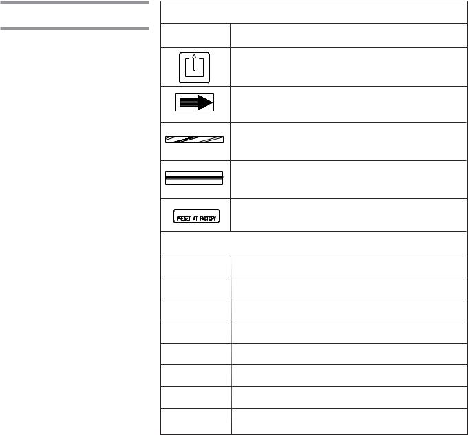
Symbols
Symbols on the Crate:
Symbol |
Definition |
TIP 'N TELL Indicator. "If TIP 'N TELL arrow point is blue, this package has been on its side or tipped over in transit. Make note on the bill of lading and check for damage. Any claims for dripping on this notation.
Maximum Relative Humidity.
This Side Up.
Keep Dry.
Fragile.
Do Not Stack.
Maximum Temperature.
Open This Side.
Symbols on the Unit:
Symbol |
Definition |
Transfer of Heat, Hot Surface.
Protective Earth (Ground).
Warning! Risk of Electrical Shock.
Attention, Consult Manual for Further Instructions.
Warning! Do Not Step Here.
Fork Lift: Place Forks of the Fork Lift Here.
1-4
122998-049 |
Uncrating/Installation Instructions |
Listing of Warnings, Cautions, and Symbols |
Symbols (cont'd)
|
Symbols on the Unit (cont'd): |
Symbol |
Definition |
|
Safety Exit: Push Here in Case of Emergency. |
|
Rotation: Direction of the Rotation Device. |
|
Emergency Stop Guard Rails: Push to Stop Washer |
|
and De-energize Control. |
|
Load Delimitation: Do not Place Load Over Marks. |
|
Factory Adjustment: Do Not Adjust. |
|
Information on the Nameplate: |
Symbol |
Definition |
MOD. |
Model Number of the Unit |
SER. |
Serial Number of the Unit |
kW |
Power Rating of the Unit. |
VOLTS |
Voltage Rating of the Unit. |
AMPS |
Amperage Rating of the Unit. |
PH/Hz |
Phase/Hertz — Frequency of the Unit. |
YEAR |
Year of Manufacturing of the Unit. |
1-5
Listing of Warnings, Cautions, and Symbols |
Uncrating/Installation Instructions |
122998-049 |
This Page Intentionally Left Blank
1-6
122998-049 |
Uncrating/Installation Instructions |
Listing of Warnings, Cautions, and Symbols |
SITE PREPARATION |
|
2 |
|
|
|
2.1 Before Installing
Equipment
Figure 2-1. Utility Service
Connections
1.Review permissible environmental conditions: This washer is designed to give optimal results in an environment where maximum relative humidity is less than 85% and maximum operating temperature is 104°F (40°C).
2.An optional seismic anchorage system is available for high risk seismic zones.
3.Review installation requirements:
a.Clearance - Clearance space shown on Equipment Drawing is necessary for easy installation and proper operation and maintenance of washer (see Equipment Drawing 122998-061).
b.Barrier wall flange(s) installation - Refer to Equipment Drawing 122998061 for installation.
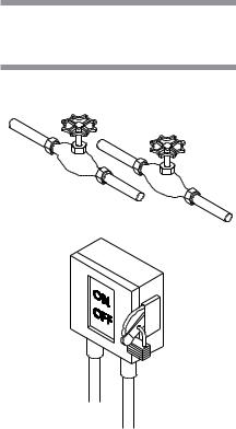
c.Utility service lines:
•To allow service on unit without shutting off building supply lines, shutoff valves (not by STERIS) should be installed on steam, air and water lines to unit (see Figure 2-1). Shutoff valves must be capable of being locked in OFF position only.
•Disconnect switch (not by STERIS) must be installed on electric supply line (see Figure 2-1).
•Disconnect switches must be marked as the disconnecting device for the equipment and must be capable of being locked in OFF position only.
•If machine is installed next to other equipment, shutoff valves and disconnect switches should be located so that service can be shut off to one piece of equipment at a time.
•The disconnect device of the equipment must be within easy reach of the operator (preferably no more than 3 feet [1 m] away from equipment).
•Utility service requirements are shown on Equipment Drawing.
d.Electricity:
•Unit requires either 208 V, 60 Hz, 3-phase, 3-wire; 380/400/415 V, 50 Hz, 3-phase, 3-wire; or 480 V, 60 Hz, 3-phase, 3-wire power.
For 208 V, 60 Hz, a 50 A disconnect switch and AWG #6 (16 mm) wire is recommended.
For 480 V, 60 Hz, a 30 A disconnect switch and AWG #10 (6 mm) wire is recommended.
For 380/400/415 V, 50 Hz, a 20 A disconnect switch and AWG #12 (4 mm2) wire is recommended.
If electrical supply is 380 V or 400 V, locate the 1000 VA transformer, inside the main electrical box, and connect red wire of primary side to 380 V (H2) tap connection.
2-1
Site Preparation |
Uncrating/Installation Instructions |
122998-049 |
•Check Equipment Drawing or Identification nameplate (located on frame of mobile mechanical core, above main electrical box, (see Figure 3-2) for proper voltage and amperage.
•This unit is overvoltage (Installation Category II).
•This equipment is not intended to be connected close to the main supply of the building.
•This equipment needs to be installed according to local electrical codes.
4.This is a Class 1 equipment
A protective conductor connection is essential for the safe operation of the equipment. Check for presence of protective conductor at equipment terminal and verify if connection is well secured inside terminal with proper torque requirement.
•Torque requirement for supply conductor terminals: (L1-L2-L3): 0.89 -1.03 lb/ft (1,2 - 1,4 N•m)
•Protective conductor terminal: 16.96 - 29.50 lb/ft (23 - 40 N•m)
5.Make sure washer is placed, as shown on Equipment Drawing, in correct relation to building supply lines. If unit is not at installation site, refer to Section 3 for proper moving instructions.
6.If washer is pit-mounted:
•Pit must be clean.
•Pit drain piping should be level with pit floor to allow water to drain.
2-2
122998-049 |
Uncrating/Installation Instructions |
Site Preparation |

UNCRATING/INSTALLATION INSTRUCTIONS |
|
3 |
|
|
|
NOTE: Use a forklift to move crates.
3.1 Open Crates NOTE: Uncrate on level floor as close to installation site as possible.
IMPORTANT: Bring in and uncrate only one crate at a time (see Figure 3-1).
3.1.1Assembled Unit A fully equipped, assembled unit should consist of two or more crates:
•Crate A: Sump, floor, roof, non-service side panels, hardware box, control panel(s), doors;
Dimensions: 89" W x 117" H x 109" L (2260 x 2972 x 2769 mm); Max. Weight: 4000 lb (1818 kg).
•Crate C: Mechanical core;
WARNING – PERSONAL INJURY AND/OR EQUIPMENT DAMAGE HAZARD: When moving the unit, use a forklift.
WARNING – LACERATION / EYE INJURY HAZARD: When removing bands, wear gloves and eye protection, and always use a tool specifically designed to cut the bands. The bands used to secure these crates can cause personal injury when cut and tension is released.
Dimensions: 49" W x 85" H x 108" L (1245 x 2159 x 2743 mm); Max. Weight: 2000 lb (909 kg).
•Crate D: Drying package (option) and/or enclosure wall option and/or ramp (option):
Dimensions: 48" W x 44" H x 60" L (1229 x 1118 x 1524 mm). Max. weight: 550 lb (250 kg).
NOTE: There is no Crate B for assembled units.
1.Bring washer as close as possible to installation site.
2.Position unit to open wooden crate from top and side. Provide a clear work area on all sides.
3.Remove transparent plastic wrap from around crate.
4.Check Tip Indicator, located on upper left side of crates (see Figure 1). Tip Indicator contains a blue compound at the bottom of the indicator. If unit has been tipped, residue from the blue compound will be found higher up in the indicator. If unit has been tipped, notify your STERIS regional office. A service technician will review the equipment and determine if unit was damaged.
5.Remove wood panels from top and sides of washer.
6.With skid under washer, lift and bring washer close to installation site.
7.Lift washer and remove skid from under washer.
8.Place washer into pit at final installation site. See Equipment Drawing (122- 998-061) and seismic anchorage report if option applies (122-997-987) for proper installation.
IMPORTANT: Be sure that suction piping is located on service side.
9. Floor mounted units:
•Use a 24" spirit level, level sump, end-to-end and side-to-side, to adjust the four leveling legs (one at each corner of sump).
•Distance from door sill and floor can be adjusted between 7" and 9" (18 cm to 23 cm).
•Make sure washer is flush with floor.
3-1
Uncrating/Installation Instructions |
Uncrating/Installation Instructionsl |
122998-049 |
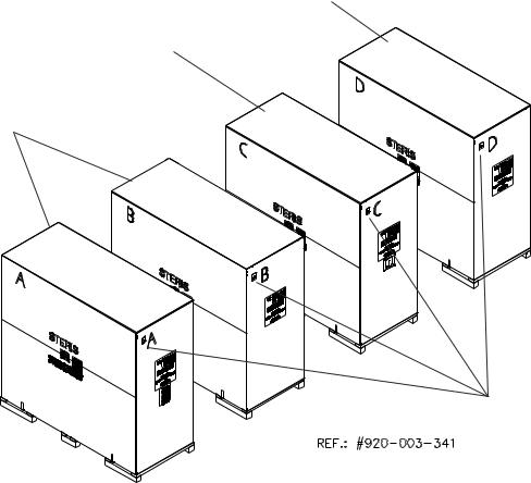
Drying Option
Mechanical Core
Basil 9500 Cage and Rack Washer
Tip Indicators
Figure 3-1. Crates
3-2
122998-049 |
Uncrating/Installation Instructions |
Uncrating/Installation Instructions |
10.Pit-mounted units:
•Use a 24”spirit level, level sump, end-to-end and side-to-side, to adjust four leveling legs (one at each corner of sump).
•To access leveling legs, external cabinet corners and front service panels may have to be removed:
a)Remove screws holding front service panel in place, and remove panel.
b)Remove screws holding non-control side external cabinetc o r n e r
panel |
in place and remove panel. |
NOTE: leveling legs on control side panels can be reached from behind control side panel without having to be removed.
11.Inside wash chamber: Cut bands and remove control(s) from bottom of wash chamber.
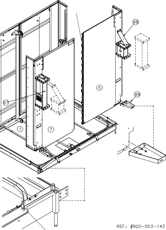
12.Install controls on service side cabinet corner (5, 7) using hardware provided on controls (97, 98), tighten all hardware (see Figure 3-4).
NOTE: Always verify with customer if the location of main control with printer corresponds to configuration required.
NOTE: Control Configuration. If controls have been changed from one end to the other, align control with control door window as follows:
1.Close locks on control door.
2.Place control next to transparent membrane as if to operate control touch pad.
3.Align control with control door window.
4.Tighten nuts.
5.Use Blank Sticker to cover printer window on secondary control side (see Figure 3-14, detail "A").
•Remove bolts holding pieces of wood securing spray headers in place.
•Remove bolts and remove wooden floor frame inside wash chamber.
•Remove pieces of wood securing doors in place.
Once unit is in place, see Section 3.2.25 (Crate C) and Section 3.3.5 (Crate D) to complete washer installation.
3-3
Uncrating/Installation Instructions |
Uncrating/Installation Instructionsl |
122998-049 |

Right Side
Non-Service Side
Mechanical Core
Left Side
Tip Indicators
Emergency Stop Pushbutton
Service Side
Ref.: 920-003-135
Nameplate
Figure 3-2. Basil® 9500 Cage and Rack Washer, Reference View Point for All Installation Locations
3-4
122998-049 |
Uncrating/Installation Instructions |
Uncrating/Installation Instructions |
3.1.2Disassembled Unit A fully equipped, disassembled unit should consist of four crates:
•Crate A: Sump, floor, roof, non-service side panels, hardware box; Dimensions: 49" W x 85" H x 108" L x (1245 x 2159 x 22743 mm); Max. weight: 2000 lb (909 kg).
•Crate B: End roof, piping, guards, doors;
WARNING – PERSONAL INJURY AND/OR EQUIPMENT DAMAGE HAZARD: When moving the unit, use a forklift.
WARNING – LACERATION / EYE INJURY HAZARD: When removing bands, wear gloves and eye protection, and always use a tool specifically designed to cut the bands. The bands used to secure these crates can cause personal injury when cut and tension is released.
Dimensions: 49" W x 85" H x 108" L x (1245 x 2159 x 22743 mm); Max. weight: 2000 lb (909 kg);
If option side panel add 200 lb (91 kg).
• Crate C: Mechanical core;
Dimensions: 49" W x 85" H x 108" L x (1245 x 2159 x 22743 mm); Max. weight: 2000 lb (909 kg).
• Crate D: Drying package (option);
Dimensions: 48" W x 44" H x 60" L x (1229 x 1118 x 1524 mm); Weight: 550 lb (250 kg);
and/or enclosure wall option, Weight: 700 lb (317 kg); and/or ramp (option);
Weight: 550 lb (250 kg).
1.Remove transparent plastic wrap from around crate.
2.Check Tip Indicator, located on upper left side of crates (see Figure 3-1). Tip indicator contains a blue compound at the bottom of the indicator. If unit has been tipped, residue from the blue compound will be found higher up in the indicator. If unit has been tipped, notify your STERIS regional office. A service technician will review the equipment and determine if unit was damaged.
3.Position wooden crate to enable opening from top and side. Provide a clear work area on all sides.
4.Remove and discard side wooden panels.
IMPORTANT: Do not remove wooden top and side crate frames. All parts must be removed from crate ends. Do not remove parts from top of crates.
NOTE: Do not remove white protective adhesive paper until after utilities are connected.
5. Mobile mechanical core:
•Check Tip Indicator, located on frame below main electrical box (see Figure 3-2). If unit has been tipped, notify your STERIS regional office. A service technician will review the equipment and determine if unit was damaged.
6.Repeat steps 1 through 3 for each crate.
IMPORTANT: Become familiar with components and installation instructions before installing washer. (see Fig. 3-2).
3-5
Uncrating/Installation Instructions |
Uncrating/Installation Instructionsl |
122998-049 |
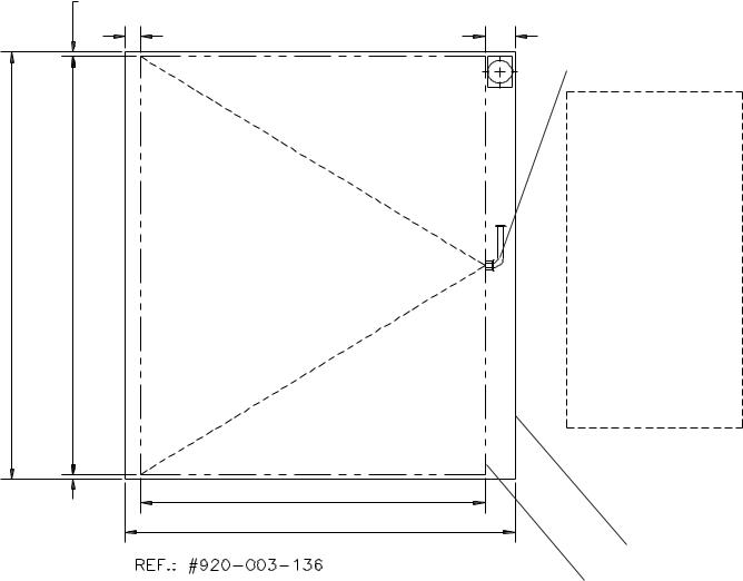
|
1" [25 mm] Min. Clearance |
|
3" [77 mm] Min. Clearance |
Pitm] [2,3994" |
Washerm] [2,3492" |
|
68-3/4" [1,75 m] Washer |
|
1" [25 mm] Min. |
|
78" [1,98 m] Pit |
6" [152 mm] Min. Suction Piping
Mechanical Core
Mechanical Core
Washer Outline
Figure 3-3. Pit Mounted Unit
3-6
122998-049 |
Uncrating/Installation Instructions |
Uncrating/Installation Instructions |

IMPORTANT: Uncrate and assemble only one crate at a time.
3.2 Disassembled
Unit Assembly
3.2.1 Crate A
NOTE: Major components in crate are numbred to assist in inventory and assembly of unit. Review crate contents by matching numbers on components to numbers listed in parenthesis ( ) and on figures.
NOTE: Bolts, washers, nuts, and other items needed for the assembly of the unit are in a box labeled HARDWARE, inside Crate A.
Contents:
•Sump, without floor and floor grating assembly (1).
•Cabinet corner panels, non-service side, left (2) and right (4).
•Cabinet corner panels, service side, left (7) and right (5).
•Roof mounting brackets (9).
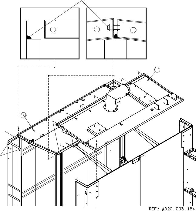
•Non service side roof (10) and service side roof (11).
•Floor frame (31).
•Floor grating sections: 1 central section (32) 2 side sections (33).
•Main Control (97).
•Remote Control (98).
•Cabinet supports (99).
•Hardware Installation Kit: bolts, silicon, etc.
3.2.2Sump Figure 3-3
1.See Equipment Drawing (122998-061) and seismic anchorage report if option applies, (122997-987) for complete installation details.
WARNING – PERSONAL INJURY AND/OR EQUIPMENT DAMAGE HAZARD: When moving the unit, use a forklift.
WARNING – LACERATION HAZARD: When removing bolts, wear gloves to potect your hands.
NOTE: For seismic installation, refer to Seismic Anchorage Instructions (included with documentation).
2. Install sump (1) on floor or in pit (if pit-mounted unit).
IMPORTANT: Be sure that suction piping is located on service side.
3.Floor mounted units:
•Use a 24” spirit level, level sump, end-to-end and side-to-side, to adjust four leveling legs (one at each corner of sump).
•Distance from door sill and floor can be adjusted between 7 and 9 inches (18 cm to 23 cm).
4.Pit-mounted units:
•Make sure that no floor covering materials, such as tile or wood, will be installed after unit is into pit. If a floor covering is required, make sure unit is flush with floor covering.
•Use a 24” spirit level, level sump, end-to-end and side-to-side, to adjust four leveling legs (one at each corner of sump).
•Make sure washer is flush with floor.
5.Floor Gratings:
a)Install floor frame (31) inserting pins in holes (non-service side).
b)Install floor gratings (center (32), sides (33) ) on floor frame.
3-7
Uncrating/Installation Instructions |
Uncrating/Installation Instructionsl |
122998-049 |
Apply Silicone
Apply Silicone
Detail C
Wall
Detail A
Angle Bracket
Detail B
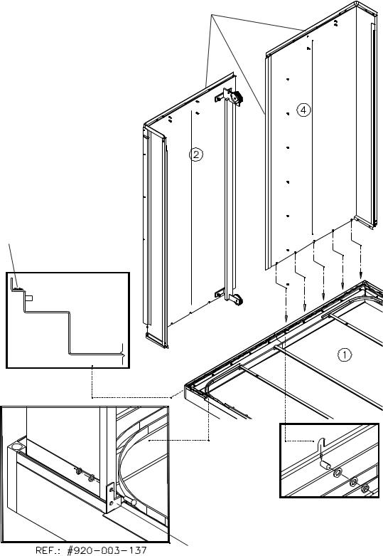
Figure 3-4. Non-Service Side Walls
3-8
122998-049 |
Uncrating/Installation Instructions |
Uncrating/Installation Instructions |
3.2.3 Non-Service Side
Walls
Figure 3-4
IMPORTANT: Two people minimum are required to assemble side walls.
1.Spread a 3/8 inch (11 mm) bead of silicone on non-service side sump base
(1).
2.Spread a 3/8 inch (11 mm) bead of silicone on top and side of left corner panel (2).
NOTE: For washer installation with no clearance on non-service side of wash cabinet, bolt non-service side panels together (step 6), before bringing panels close to the washer.
3.Bring left corner panel (2) using installation cutout handles. Seat over sump, behind angle brackets (see Detail B).
NOTE: Finger-tighten the 1/4 - 20 bolts first to support the panel.
4.Finger-tighten hardware holding corner panels to sump, use 5/16 washers, 5/16 spring washers, and nuts at bottom of sump (see Detail A). Use 1/4 - 20 x 3/4 bolts, 1/4 lockwashers, and 1/4-20 nuts for angle brackets (see Detail B).
5.Repeat steps 2 through 4 to install right non-service corner panels (4).
6.From outside, on non-service side, fix non-service side panels together, using four 5/16-18 x3/4 bolts, eight 5/16 washers, and four 5/16 lockwashers provided.
7.Tighten wall to sump and secure wall to angle brackets (see Detail B).
8.Spread a 3/8 inch (11 mm) bead of silicone on central joint of panel (see Detail C).
3-9
Uncrating/Installation Instructions |
Uncrating/Installation Instructionsl |
122998-049 |
Apply Silicone
Angle Bracket
Detail A
Figure 3-5. Service Side Panels
3-10
122998-049 |
Uncrating/Installation Instructions |
Uncrating/Installation Instructions |
3.2.4 Service Side Panels Figures 3-4 and 3-5
IMPORTANT: Two people minimum are required to assemble side walls.
1.Apply a 3/8 inch (11 mm) bead of silicone on service side sump base (1).
2.Apply a 3/8 inch (11 mm) bead of silicone on side of right corner panels (5).
3.Bring right corner service side panel (5) and seat over sump, behind angle brackets (see Figure 3-4, Detail A).
NOTE: Finger-tighten the 1/4-20 bolts first to support the panel.
4.Finger-tighten hardware holding corner panels to sump. Use 5/16 washers, 5/16 springwashers and nuts at bottom of sump (see Figure 3-4, Detail A). Use 1/4 - 20 x 3/4 bolts, 1/4 lockwashers, and 1/4-20 nuts for angle brackets (see Figure 3-4 Detail B).
5.Repeat steps 2 through 4 to install left corner service side (6).
6.From outside, on service side, fix service side panels together, using four 5/16-18 x 3/4 bolts, eight 5/16 washers, four 5/16 lockwashers, and nuts provided.
7.Tighten wall to sump and secure wall to angle brackets.
3.2.5Control Single door units:
Configuration
Install Main Control (97) on unit, using 1/4 washers and 1/4-20 nuts provided. Make final adjustment when installing cabinet and tighten hardware (39, or 40) (See Figure 3-4 and 3-11).
Double door units:
NOTE: Controls can be installed to suit customer requirements.
Factory installation: Main Control, (97) is installed to the right and remote control (98) is installed to the left (operator facing service side of unit).
1.To change printer location, dismantle both support with controls, (controls should stay on supports) (see Figure 3-5) and re-install on opposite ends of washer, using 1/4 washers and 1/4-20 nuts provided.
2.Install control cabinet supports (99), one bottom right and one bottom left corner, using 1/4 washers and 1/4-20 nuts provided. Make final adjustments when installing cabinet (39, 40) and tghten hardware (see Figure 3-14).
3-11
Uncrating/Installation Instructions |
Uncrating/Installation Instructionsl |
122998-049 |
Studs
Figure 3-6. Temporary Roof Support
3-12
122998-049 |
Uncrating/Installation Instructions |
Uncrating/Installation Instructions |
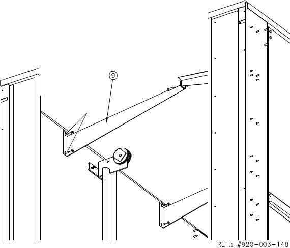
3.2.6 Temporary Roof
Support
Figure 3-6
1.On each side of washer, install temporary roof mounting supports (9). Position supports so they are in the highest position. Bolt temporary roof mounting supports to wall, using 5/16-18 nuts and 5/16 washers provided.
2.Bolt supports together in the middle with 5/16 -18 x 3/4 bolts, 5/16 washers and 5/16 nuts.
3-13
Uncrating/Installation Instructions |
Uncrating/Installation Instructionsl |
122998-049 |
Detail A
Roof, apply Silicone
Side Wall Stud
Apply
Silicone
Figure 3-7. Roof
3-14
122998-049 |
Uncrating/Installation Instructions |
Uncrating/Installation Instructions |
Loading...