

Bard WL4822, WL4823, WL6023, WL602N Installation Instructions Manual

INSTALLATION INSTRUCTIONS
WALL MOUNTED
PACKAGE AIR CONDITIONERS
MODELS
WL4822
WL4823
WL6022
WL6023
WL602N
Bard Manufacturing Company
Bryan, Ohio 43506
Since 1914...Moving ahead just as planned.
Manual : 2100-351D
Supersedes: 2100-351C
File: Volume III Tab 16
Date: 09-20-01
© Copyright 2001

Contents
Getting Other Information and Publications 1
Wall Mount General Information
Air Conditioning Wall Mount Model Nomenclature.2
Shipping Damage ................................................... 6
General ...............................................................6
Duct Work...............................................................6
Condensate Drain...................................................6
Filters ...............................................................6
Installation Instructions
Wall Mounting Information......................................7
Mounting the Unit ...................................................7
Wiring – Main Power ............................................13
Wiring – Low Voltage Wiring ................................ 13
Figures
Figure 1 Unit Dimensions .....................................3
WA602N, WA6023, WA4823
Figure 2 Unit Dimensions .....................................4
WA6022, WA4822
Figure 3 Mounting Instructions.............................8
WA602N, WA6023, WA4823
Figure 4 Mounting Instructions.............................9
WA6022, WA4822
Figure 5 Electric Heat Clearance .......................10
Figure 6 Wall Mounting Instructions...................11
Figure 7 Wall Mounting Instructions...................11
Figure 8 Common Wall Mounting Installations. ..12
Figure 9 Unit 24V Terminal Board ......................14
Figure 10 Fan Blade Setting.................................17
Start Up
Important Installer Note ........................................15
Crankcase Heaters...............................................15
High Pressure Switch ...........................................15
Three Phase Scroll Compressor Start Up ............15
Service Hints ........................................................15
Sequence of Operation.........................................15
Compressor Control Module.................................15
Adjustments..........................................................16
Phase Monitor ......................................................16
Pressure Service Ports.........................................16
Troubleshooting
Fan Blade Setting Dimensions .............................17
Removal of Fan Shroud........................................17
Refrigerant Charge ............................................... 17
Pressure Table......................................................18
Optional Accessories............................................ 19
T
ables
Table 1 Electric Heat Table .................................2
Table 2 Electrical Specifications .........................5
Table 3 Thermostat Wire Size ..........................13
Table 4 Wall Thermostat and Subbase
Combinations .......................................13
T able 5 Fan Blade Dimensions.........................17
T able 6 Indoor Blower Performance .................17
Table 7 Refrigerant Charge...............................17
Table 8 Rated CFM and Rated ESP ................. 17
Table 9 Maximum ESP of Operation
Electric Heat Only ................................18
Table 10 Pressure Table .....................................18
Table 11 Optional Accessories ...........................19

Getting Other Information and Publications
These publications can help you install the air conditioner
or heat pump. You can usually find these at your local
library or purchase them directly from the publisher. Be
sure to consult current edition of each standard.
National Electrical Code........................ ANSI/NFPA 70
Standard for the Installation................... ANSI/NFPA
90A
of Air Conditioning and
Ventilating Systems
Standard for Warm Air .......................... ANSI/NFPA
90B
Heating and Air
Conditioning Systems
Load Calculation for .............................. ACCA Manual J
Residential Winter and
Summer Air Conditioning
For more information, contact these
publishers:
ACCA Air Conditioning Contractors of America
1712 New Hampshire Ave. N.W.
Washington, DC 20009
Telephone: (202) 483-9370
Fax: (202) 234-4721
ANSI American National Standards Institute
11 West Street, 13th Floor
New York, NY 10036
Telephone: (212) 642-4900
Fax: (212) 302-1286
ASHRAE American Society of Heating Refrigerating,
and Air Conditioning Engineers, Inc.
1791 Tullie Circle, N.E.
Atlanta, GA 30329-2305
Telephone: (404) 636-8400
Fax: (404) 321-5478
Duct Design for Residential................... ACCA Manual
D Winter and Summer Air Conditioning
and Equipment Selection
Manufactured under the following U.S. patent numbers:
5,485,878; 5,301,777; 5,002,116; 4,924,934;
4,875,520; 4,825,936; 4,432,409
NFPA National Fire Protection Association
Batterymarch Park
P.O. Box 9101
Quincy, MA 02269-9901
Telephone: (800) 344-3555
Fax: (617) 984-7057
Manual 2100-351
Page 1
WALL MOUNT GENERAL INFORMATION
AIR CONDITIONING WALL MOUNT MODEL NOMENCLATURE
MODEL NUMBER
CAPACITY
60 - 5 Ton
FEATURE CODE
3 - 3 ton air openings
on 5 ton cabinet
2 - 2 ton air openings
on 5 ton cabinet
NOTE: All vent options are without exhaust capability. May require separate field supplied barometric relief in building.
REVISIONS
WL 60 2 3 A 10 X N X X X A
COLOR OPTIONS
X - Beige (Standard)
1 - White
2 - Mesa Tan
4 - Buckeye Gray
VOLTS & PHASE
A - 230/208/60/1
B - 230/208/60/3
KW
VENTILATION OPTIONS
B - Blank-off Plate
FILTER OPTIONS
N - No Filter WL4823, WL6023, WL602N models ONLY
X - One Inch Throwaway Filter WL4822, WL6022 models ONLY
W- One Inch Washable Filter WL4822, WL6022 models ONLY
P - Two Inch Pleated Filter WL4822, WL6022 models ONLY
Model WL602N is identical to Model WL6023. All references in this
manual to WL6023 apply to WL602N also.
CONTROL MODULES
COIL OPTIONS
X - Standard
1 - Phenolic Coated Evaporator
2 - Phenolic Coated Condenser
3 - Phenolic Coated Evaporator
and Condenser
OUTLET OPTIONS
X - Front (Standard)
TABLE 1
ELECTRIC HEAT TABLE
sledoM
1-V0421-V8021-V0421-V802
WK
SPMAHUTBSPMAHUTBSPMAHUTBSPMAHUTB
0.58.02050,711.81008,21------------
0.9------------7.12006,037.81030,32
0.016.14031,432.63006,52------------
YLNOA3206LWYLNOB3206LW
WL4822A, WL4822B, WL4823A, WL4823B, WL6022A, WL6022B are not
approved for use with electric heat.
Manual 2100-351
Page 2
Manual 2100-351
Page 3
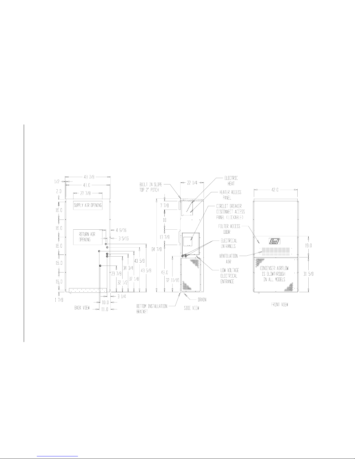
FIGURE 1
UNIT DIMENSIONS
WL602N, WL6023, WL4823 ONLY
MIS-1451
Manual 2100-351
Page 4
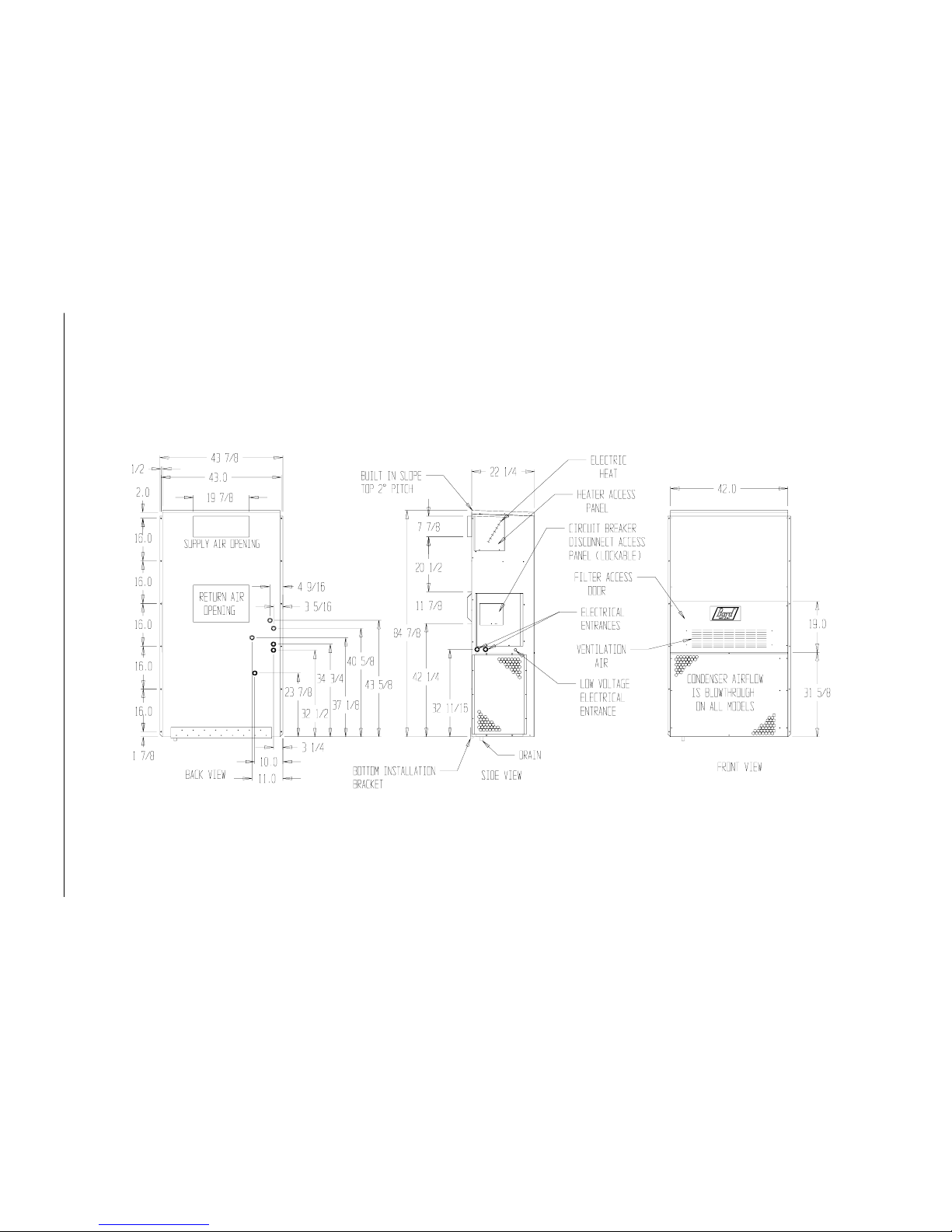
FIGURE 2
UNIT DIMENSIONS
WL6022, WL4822 ONLY
MIS-1452
Manual 2100-351
Page 5
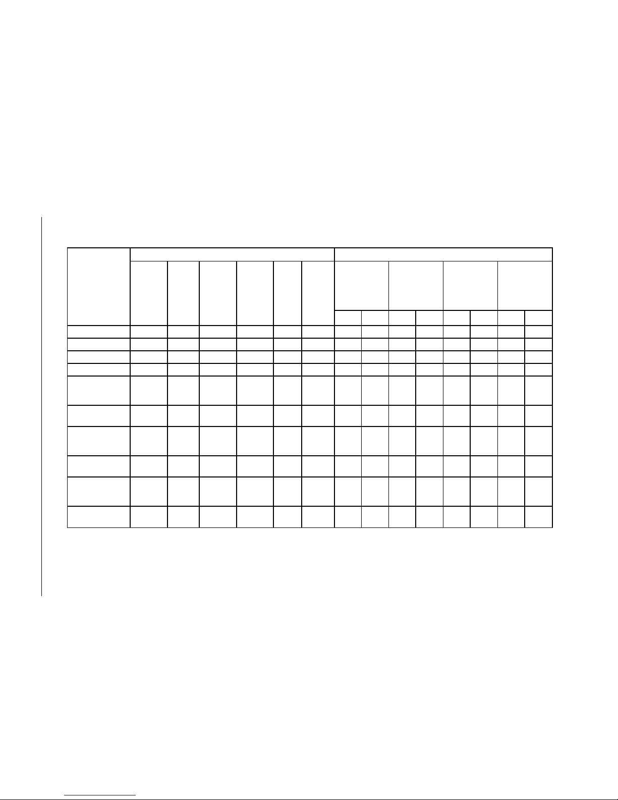
TABLE 2
ELECTRICAL SPECIFICATIONS
j
k
l
Maximum size of the time delay fuse or HACR type circuit breaker for protection of field wiring conductors.
Based on 75° C copper wire. All Wiring must conform to NEC and all local codes.
These “minimum Circuit Ampacity” values are to be used for sizing the field power conductors. Refer to the National
Electric Code (latest revision), article 310 for power conductor sizing. CAUTION: When more than one field power
conductor circuit is run through one conduit, the conductors must be derated. Pay special attention to note 8 of table
310 regarding Ampacity Adjustment Factors when more than 3 conductors are in a raceway.
ledoM
TIUCRICELGNIS TIUCRICLAUD
detaR
&stloV
esahP
.oN
dleiF
rewoP
stiucriC
3
muminiM
tiucriC
yticapmA
1
mumixaM
lanretxE
roesuF
.tkC
rekaerB
2
dleiF
rewoP
eriW
eziS
2
dnuorG
eriW
eziS
3
muminiM
tiucriC
yticapmA
1
mumixaM
esuFlanretxE
ro
rekaerB.tkC
2
rewoPdleiF
eziSeriW
2
dnuorG
eziSeriW
ATKCBTKCATKCBTKCATKCBTKCATKCBTKC
Z0A,00A2284LW1-802/03218305801A/NA/NA/NA/NA/NA/NA/NA/N
Z0B,00B2284LW3-802/03216253801A/NA/NA/NA/NA/NA/NA/NA/N
Z0A,00A3284LW1-802/03218305801A/NA/NA/NA/NA/NA/NA/NA/N
Z0B,00B3284LW3-802/03216253801A/NA/NA/NA/NA/NA/NA/NA/N
Z0A,00A2206LW
50A
01A
1-802/032
1
1
1
44
44
55
06
06
06
8
8
6
01
01
01
A/N
A/N
A/N
A/N
A/N
A/N
A/N
A/N
A/N
A/N
A/N
A/N
A/N
A/N
A/N
A/N
A/N
A/N
A/N
A/N
A/N
A/N
A/N
A/N
Z0B,00B2206LW
90B
3-802/032
1
1
23
43
54
54
8
8
01
01
A/N
A/N
A/N
A/N
A/N
A/N
A/N
A/N
A/N
A/N
A/N
A/N
A/N
A/N
A/N
A/N
Z0A,00A3206LW
50A
01A
1-802/032
1
1
1
44
44
55
06
06
06
8
8
6
01
01
01
A/N
A/N
A/N
A/N
A/N
A/N
A/N
A/N
A/N
A/N
A/N
A/N
A/N
A/N
A/N
A/N
A/N
A/N
A/N
A/N
A/N
A/N
A/N
A/N
Z0B,00B3206LW
90B
3-802/032
1
1
23
43
54
54
8
8
01
01
A/N
A/N
A/N
A/N
A/N
A/N
A/N
A/N
A/N
A/N
A/N
A/N
A/N
A/N
A/N
A/N
Z0A,00AN206LW
50A
01A
1-802/032
1
1
1
44
44
55
06
06
06
8
8
6
01
01
01
A/N
A/N
A/N
A/N
A/N
A/N
A/N
A/N
A/N
A/N
A/N
A/N
A/N
A/N
A/N
A/N
A/N
A/N
A/N
A/N
A/N
A/N
A/N
A/N
Z0B,00BN206LW
90B
3-802/032
1
1
23
43
54
54
8
8
01
01
A/N
A/N
A/N
A/N
A/N
A/N
A/N
A/N
A/N
A/N
A/N
A/N
A/N
A/N
A/N
A/N
 Loading...