

Page 1

INSTALLATION INSTRUCTIONS
WALL MOUNTED
PACKAGE HEAT PUMP
Models
WH183
WH242
Bard Manufacturing Company
Bryan, Ohio 43506
Since 1914...Moving ahead just as planned.
Manual : 2100-373A
Supersedes: 2100-373
File: Volume III Tab 17
Date: 05-13-02
© Copyright 2002
Page 2

Contents
Getting Other Informations and Publications ........ 1
Wall Mount General Information ............................. 2
Heat Pump Wall Mount Model Nomenclature.......... 2
Shipping Damage .................................................... 2
General ................................................................ 2
Duct Work................................................................ 4
Filters ................................................................ 5
Fresh Air Intake........................................................ 5
Condensate Drain .................................................... 5
Installation Instructions ........................................... 6
Wall Mounting Information ....................................... 6
Mounting the Unit ..................................................... 6
Wiring – Main Power.............................................. 10
Wiring – Low Voltage Wiring ..................................11
Compressor Cutoff Thermostat and
Outdoor Thermostats ..............................................1 1
Heat Anticipation.................................................... 12
Thermostat Indicator Lamps .................................. 12
Compressor Malfunction Light ............................... 12
Figures
Figure 1 Unit Dimensions...................................... 3
Figure 2 Fresh Air Damper Assembly ................... 5
Figure 3 Mounting Instructions.............................. 7
Figure 4 Wall Mounting Instructions...................... 8
Figure 5 Wall Mounting Instructions...................... 8
Figure 6 Common Wall Mounting Installations...... 9
Figure 7 Unit 24V Terminal Board ....................... 10
Figure 8 Compressor Cutoff and Outdoor
Thermostat Wiring ................................. 11
Figure 9 Start Up Procedure Decal ..................... 13
Figure 10 Defrost Control Board ........................... 14
Figure 11 Fan Blade Setting ................................. 17
Figure 12 Compressor Burnout
Cleanup Procedure ............................... 13
Start Up ................................................................... 13
Important Installer Note ......................................... 13
Crankcase Heaters................................................ 13
Service Hints ......................................................... 13
Sequence of Operation.......................................... 13
Pressure Service Ports .......................................... 14
Defrost Cycle ......................................................... 14
Troubleshooting ..................................................... 15
Solid State Heat Pump Control
Troubleshooting Procedure ................................... 15
Checking Temperature Sensor Outside
Unit Circuit ............................................................. 16
Fan Blade Setting Dimensions .............................. 17
Removal of Fan Shroud......................................... 17
Refrigerant Charge ................................................ 17
Pressure Tables ..................................................... 18
Optional Accessories............................................. 19
Tables
Table 1 Electric Heat Table .................................. 1
Table 2 Fuse, HACR Breakers, Wire Size........... 4
Table 3 Thermostat Wire Size ............................11
Table 4 Wall Thermostat and Subbase
Combinations ........................................ 12
Table 5 Troubleshooting .................................... 15
Table 6 Fan Blade Dimensions.......................... 17
Table 7 System Charge Ratings ........................ 17
Table 8 Indoor Blower Performance .................. 17
Table 9 Rated CFM and Raded ESP................. 17
Table 10 Maximum ESP of Operation ................. 17
Table 11 Pressure Table ...................................... 18
Table 12 Pressure Table ...................................... 18
Table 13 Optional Accessories ............................ 19
Page 3

Getting Other Information and Publications
These publications can help you install the air
conditioner or heat pump. You can usually find these at
your local library or purchase them directly from the
publisher. Be sure to consult current edition of each
standard.
National Electrical Code ......................ANSI/NFPA 70
Standard for the Installation ................. ANSI/NFPA
90A
of Air Conditioning and
Ventilating Systems
Standard for Warm Air.........................ANSI/NFPA
90B
Heating and Air
Conditioning Systems
Load Calculation for.............................ACCA Manual J
Residential Winter and
Summer Air Conditioning
For more information, contact these
publishers:
ACCA Air Conditioning Contractors of America
1712 New Hampshire Ave. N.W.
Washington, DC 20009
Telephone: (202) 483-9370
Fax: (202) 234-4721
ANSI American National Standards Institute
11 West Street, 13th Floor
New York, NY 10036
Telephone: (212) 642-4900
Fax: (212) 302-1286
ASHRAEAmerican Society of Heating Refrigerating,
and Air Conditioning Engineers, Inc.
1791 Tullie Circle, N.E.
Atlanta, GA 30329-2305
Telephone: (404) 636-8400
Fax: (404) 321-5478
Duct Design for Residential .................ACCA Manual
D Winter and Summer Air Conditioning
and Equipment Selection
NFPA National Fire Protection Association
Batterymarch Park
P.O. Box 9101
Quincy, MA 02269-9901
Telephone: (800) 344-3555
Fax: (617) 984-7057
Manual 2100-373
Page 1
Page 4
WALL MOUNT GENERAL INFORMATION
HEAT PUMP WALL MOUNT MODEL NOMENCLATURE
MODEL NUMBER
CAPACITY
18 - 1 1/2 Ton
24 - 2 Ton
36 - 3 Ton
48 - 4 Ton
60 - 5 Ton
VOLTS & PHASE
A - 230/208/60/1
B - 230/208/60/3
C - 460/60/3
NOTE: For 0 KW and circuit breakers (230/208 Volt) or pull disconnects (460 Volt) applications, insert 0Z in the KW field of model number.
REVISIONS
WH 24 2 — A 08 X X X X X B
COLOR OPTIONS
X - Beige
(Standard)
1 - White
2 - Mesa Tan
3 - Colonial White
4 - Buckeye Gray
FILTER OPTIONS
X - One Inch Throwaway (Standard)
W- One Inch Washable
P - Two Inch Pleated
KW
VENTILATION OPTIONS
X - Barometric Fresh Air Damper
(Standard)
B - Blank-off Plate
M - Motorized Fresh Air Damper
V - Commercial Room Ventilator
-
Motorized with Exhaust
E - Economizer (Internal) - Fully
Modulating with Exhaust
R - Energy Recovery Ventilator -
with Exhaust
CONTROL MODULES
(See Chart Below)
COIL OPTIONS
X- Standard
1 - Phenolic Coated Evaporator
2 - Phenolic Coated Condenser
3 - Phenolic Coated Evaporator
and Condenser
OUTLET OPTIONS
X- Front (Standard)
T - Top (on WH30 and
WH36 models.
TABLE 1
ELECTRIC HEAT TABLE
sledoMA-381HWA-242HWB-242HWC-242HW
1-0421-8021-0421-8023-0423-8023-064
WKAUTBAUTBAUTBAUTBAUTBAUTBAUTB
4
8
7.61056314.41042017.61056314.4104201
3.33003728.82574023.33003728.8257402
6
SHIPPING DAMAGE
Upon receipt of equipment, the carton should be
checked for external signs of shipping damage. If
damage is found, the receiving party must contact the
last carrier immediately, preferably in writing,
requesting inspection by the carrier’s agent.
GENERAL
The equipment covered in this manual is to be installed
by trained, experienced service and installation
technicians.
The refrigerant system is completely assembled and
charged. All internal wiring is complete.
The unit is designed for use with or without duct work.
Flanges are provided for attaching the supply and return
ducts.
4.41005025.21063512.757402
These instructions explain the recommended method to
install the air cooled self-contained unit and the
electrical wiring connections to the unit.
These instructions and any instructions packaged with
any separate equipment required to make up the entire
air conditioning system should be carefully read before
beginning the installation. Note particularly “Starting
Procedure” and any tags and/or labels attached to the
equipment.
While these instructions are intended as general
recommended guide, they do not supersede any national
and/or local codes in any way. Authorities having
jurisdiction should be consulted before the installation
is made. See Page 1 for information on codes and
standards.
Manual 2100-373
Page 2
Page 5
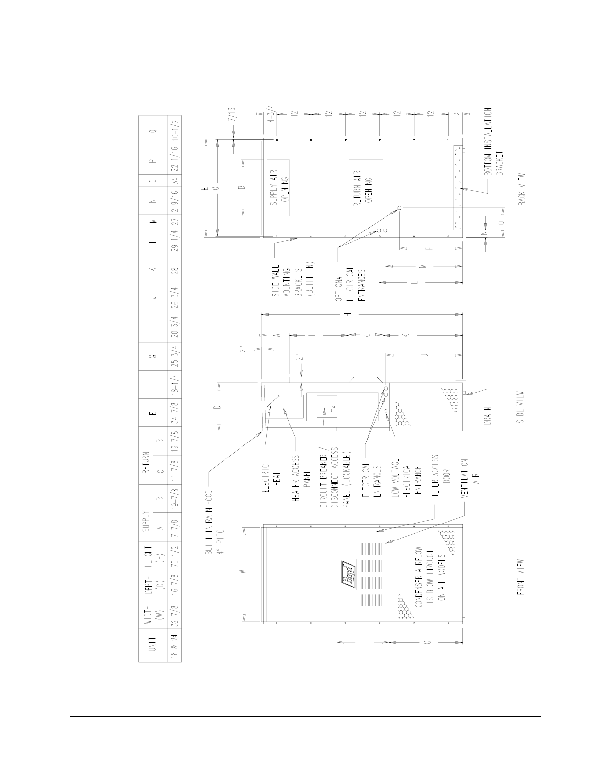
MIS-992
FIGURE 1
UNIT DIMENSIONS
Manual 2100-373
Page 3
Page 6

TABLE 2
ELECTRICAL SPECIFICATIONS
TIUCRICELGNIS
j
mumixaM
detaR
stloV
dna
ledoM
Z0A,00A-381HW
40A
l 80A
Z0A,00A-242HW
40A
l 80A
Z0B,00B-242HW
60B
Z0C,00C-242HW
60C
Maximum size of the time delay fuse or HACR type circuit breaker for protection
Q
of field wiring conductors.
Based on 75° C copper wire. All wiring must conform to NEC and all local
R
codes.
Maximum KW that can operate with heat pump on.
S
These “Minimum Circuit Ampacity” values are to be used for sizing the field
T
power conductors. Refer to the National Electric Code (latest revision), article
310, for power conductor sizing.
power conductor circuit is run through one conduit the conductors must be
derated. Pay special attention to note 89 of table 310 regarding Ampacity
Adjustment Factors when more than 3 are in a raceway.
esahP
1-802/032
1-802/032
1-802/032
3-064
dleiF.oN
rewoP
stiucriC
1
1
1
1
1
1
1
1
1
1
m
muminiM
tiucriC
yticapmA
71
83
95
81
93
06
51
33
8
71
CAUTION: When more than one field
lanretxE
roesuF
tiucriC
rekaerB
52
04
06
52
04
06
02
53
51
02
k
6
6
8
dleiF
rewoP
21
01
21
01
21
41
21
k
dnuorG
eziSeriW
eziSeriW
21
01
01
21
01
01
21
01
41
21
Size of unit for a proposed installation should be based
on heat loss calculation made according to methods of
Air Conditioning Contractors of America (ACCA). The
air duct should be installed in accordance with the
Standards of the National Fire Protection Association
for the Installation of Air Conditioning and Ventilating
systems of Other Than Residence Type, NFPA No.
90A, and Residence Type Warm Air Heating and Air
Conditioning Systems, NFPA No. 90B. Where local
regulations are at a variance with instructions, installer
should adhere to local codes.
DUCT WORK
Any heat pump is more critical of proper operating
charge and an adequate duct system that a straight air
conditioning unit. All duct work, supply and return,
must be properly sized for the design air flow
requirement of the equipment. Air Conditioning
Contractors of America (ACCA) is an excellent guide
Manual 2100-373
Page 4
to proper sizing. All duct work or portions thereof not
in the conditioned space should be properly insulated in
order to both conserve energy and prevent condensation
or moisture damage.
Refer to Table 10 for maximum static pressure
available for duct design.
Design the duct work according to methods given by the
Air Conditioning Contractors of America (ACCA).
When duct runs through unheated spaces, it should be
insulated with a minimum of one inch of insulation.
Use insulation with a vapor barrier on the outside of the
insulation. Flexible joints should be used to connect the
duct work to the equipment in order to keep the noise
transmission to a minimum.
A 1/4 inch clearance to combustible material for the
first three feet of duct attached to the outlet air frame is
required. See Pages Wall Mounting Instructions and
Figure 3 for further details.
Page 7
Ducts through the walls must be insulated and all joints
taped or sealed to prevent air or moisture from entering
the wall cavity.
CAUTION
Some installations may not require any return
air duct. A metallic return air grille is required
with installations not requiring a return air
duct. The spacing between louvers on the
grille shall not be larger than 5/8 inches.
Any grille that meets the 5/8 inch louver criteria may be
used. It is recommended that Bard Return Air Grille
Kit RG2 thru RG5 or RFG2 thru RFG5 be installed
when no return duct is used. Contact distributor or
factory for ordering information. If using a return air
filter grille, filters must be of sufficient size to allow a
maximum velocity of 400 fpm.
NOTE: If no return air duct is used, applicable
installation codes may limit this cabinet to
installation only in a single story structure.
FILTERS
A 1 inch throwaway filter is supplied with each unit.
The filter slides into position making it easy to service.
This filter can be serviced from the outside by removing
the service door. A 1 inch washable filter and a 2 inch
pleated filter are also available as optional accessories.
The internal filter brackets are adjustable to
accommodate the 2 inch filter by loosening two (2)
screws in each bracket assembly and sliding the
brackets apart to the required width and retightening the
four (4) screws.
FRESH AIR INTAKE
All units are built with fresh air inlet slots punched in
the service panel.
If the unit is equipped with a fresh air damper assembly,
the assembly is shipped already attached to the unit.
The damper blade is locked in the closed position. To
allow the damper to operate, the maximum and
minimum blade position stops must be installed. See
Figure 2.
All capacity, efficiency, and cost of operation
information as required for Department of Energy
“Energyguide” Fact Sheets is based upon the fresh air
blank-off plate in place and is recommended for
maximum energy efficiency.
The blank-off plate is available upon request from the
factory and is installed in place of the fresh air damper
shipped with each unit.
FIGURE 2
FRESH AIR DAMPER ASSEMBLY
BLADE IS LOCKED
CLOSED FOR
SHIPPING
MIS-938
CONDENSATE DRAIN
A plastic drain hose extends from the drain pan at the
top of the unit down to the unit base. There are
openings in the unit base for the drain hose to pass
through. In the event the drain hose is connected to a
drain system of some type, it must be an open or vented
type system to assure proper drainage.
Manual 2100-373
Page 5
Page 8

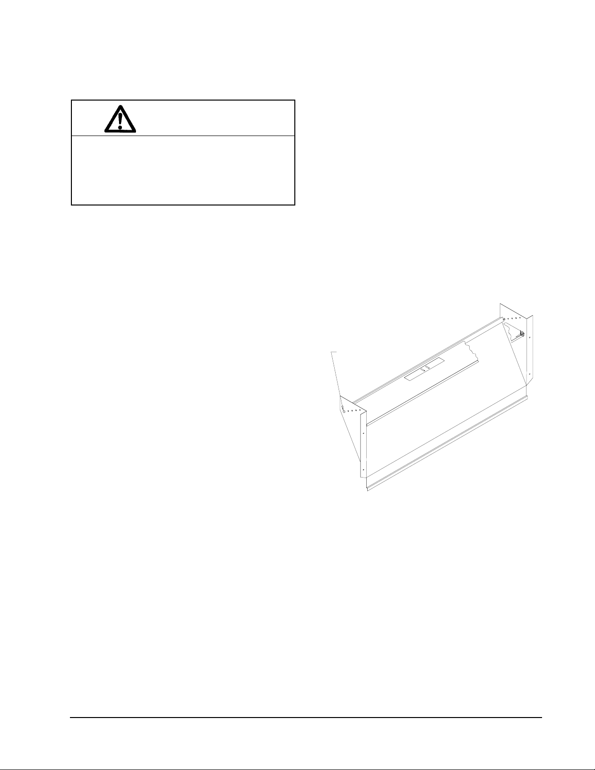
INST ALLATION INSTRUCTIONS
WALL MOUNTING INFORMATION
1. These units are secured by wall mounting brackets
which secure the unit to the outside wall surface at
both sides. A bottom mounting bracket is provided
for ease of installation, but is not required.
2. On wood frame walls, the wall construction must be
strong and rigid enough to carry the weight of the
unit without transmitting any unit vibration.
3. Concrete block walls must be thoroughly inspected
to insure that they are capable of carrying the weight
of the unit being installed.
4. The unit is suitable for 0 inch clearance from the
unit, and from the supply and return air ducts.
MOUNTING THE UNIT
1. Two holes for the supply and return air openings
must be cut through the wall as shown in Figure 3.
2. Locate and mark lag bolt locations and bottom
mounting bracket location, if desired. See Figure 3.
3. Mount bottom mounting bracket, if used.
4. Hook top rain flashing under back bend of top. Top
rain flashing is shipped secured to the right side of
the back.
5. Position unit in opening and secure with 5/16 lag
bolts. Use 5/16” diameter flat washers on the lag
bolts.
6. Secure rain flashing to wall and caulk across entire
length of top. See Figure 3.
7. For additional mounting rigidity, the return air and
supply air frames or collars can be drilled and
screwed or welded to the structural wall itself
(depending upon wall construction). Be sure to
observe required clearance if combustible wall.
8. On side by side installations, maintain a minimum
of 20 inches clearance on right side of unit to allow
access to control panel and heaters, and to allow
proper airflow to the outdoor coil. Additional
clearance may be required to meet local or national
codes.
Manual 2100-373
Page 6
Page 9

FIGURE 3
MOUNTING INSTRUCTIONS
Manual 2100-373
Page 7
MIS-353
Page 10

FIGURE 4
WALL MOUNTING INSTRUCTIONS
SEE FIGURE 3 – MOUNTING INSTRUCTIONS
FIGURE 5
WALL MOUNTING INSTRUCTIONS
SEE UNIT DIMENSIONS, FIGURE 1, FOR ACTUAL DIMENSIONS
MIS-548
MIS-549
Manual 2100-373
Page 8
Page 11

FIGURE 6
COMMON WALL MOUNTING INSTALLATIONS
MIS-550
Manual 2100-373
Page 9
Page 12

WIRING – MAIN POWER
Refer to the unit rating plate for wire sizing information
and maximum fuse or “HACR” type circuit breaker
size. Each outdoor unit is marked with a “Minimum
Circuit Ampacity”. This means that the field wiring
used must be sized to carry that amount of current.
Depending on the installed KW of electric heat, there
may be two field power circuits required. If this is the
case, the unit serial plate will so indicate. All models
are suitable only for connection with copper wire. Each
unit and/or wiring diagram will be marked “Use Copper
Conductors Only”. These instructions must be
adhered to. Refer to the National Electrical code
(NEC) for complete current carrying capacity data on
the various insulation grades of wiring material. All
wiring must conform to NEC and all local codes.
The electrical data lists fuse and wire sizes (75° C
copper) for all models, including the most commonly
used heater sizes. Also shown are the number of field
power circuits required for the various models with
heaters.
UNIT 24V TERMINAL BOARD
The unit rating plate lists a “Maximum Time Delay
Relay Fuse” or “HACR” type circuit breaker that is to
be used with the equipment. The correct size must be
used for proper circuit protection and also to assure that
there will be no nuisance tripping due to the momentary
high starting current of the compressor motor.
The disconnect access door on this unit may be locked
to prevent unauthorized access to the disconnect. To
convert for the locking capability, bend the tab located
in the bottom left hand corner of the disconnect opening
under the disconnect access panel straight out. This tab
will now line up with the slot in the door. When shut a
padlock may be placed through the hole in the tab
preventing entry.
FIGURE 7
IMPORTANT NOTE: Only the thermostat and subbase combinations as shown in Figure 7 will work with this
equipment. The thermostat and subbase must be matched, and the correct operation can be
assured only be proper selection and application of these parts.
Manual 2100-373
Page 10
Page 13

WIRING – LOW VOLTAGE WIRING
230/208V, 1 phase and 3 phase equipment dual primary
voltage transformers. All equipment leaves the factory
wired on 240V tap. For 208V operation, reconnect
from 240V to 208V tap. The acceptable operating
voltage range for the 240 and 208V taps are:
TAP RANGE
240 253 - 216
208 220 - 187
NOTE: The voltage should be measured at the field
power connection point in the unit and while the
unit is operating at full load (maximum
amperage operating condition).
Nine (9) wires should be run from thermostat subbase
to the 24V terminal board in the unit. A nine
conductor, 18 gauge copper, color-coded thermostat
cable is recommended.. The connection points are
shown in Figure 7.
TABLE 3
THERMOSTAT WIRE SIZE
mumixaM
remrofsnarT
AVALFeguaGeriW
553.2
eguag02
eguag81
eguag61
eguag41
eguag21
ecnatsiD
teeFnI
54
06
001
061
052
COMPRESSOR CUTOFF THERMOSTAT
AND OUTDOOR THERMOSTATS
Heat pump compressor operation at outdoor
temperatures below 0° F are neither desirable not
advantageous in terms of efficiency. Since most
equipment at time of manufacture is not designated for
any specific destination of the country and most of the
equipment is installed in areas not approaching the
lower outdoor temperature range, the compressor
cutoffs are not factory installed.
Outdoor thermostats are available to hold off various
banks of electric heat until needed as determined by
outdoor temperature. The set point of either type of
thermostat is variable with geographic region and sizing
of the heating equipment to the structure. Utilization of
the Heating Application Data and the heat loss
calculation of the building are useful in determining the
correct set points.
See Figure 8 for compressor cutoff and outdoor
thermostat wiring.
FIGURE 8 – COMPRESSOR CUTOFF AND OUTDOOR THERMOSTAT WIRING
4 & 8 KW 1 Phase – 6 KW 3 Phase
MIS-409
Manual 2100-373
Page 11
Page 14

HEAT ANTICIPATION
Group A and Group B thermostats shown in Table 4
have a fixed heat anticipator for stage 1 with no
adjustment required. Stage 2 has an adjustable
anticipator for the W2 connection and fixed for the W3
connection. Both the W2 and W3 circuits are
controlled by the stage 2 bulb. The only heat
anticipator that needs to be checked is stage 2 and it
should be set to match the load carried by the W2
circuit. The normal factory wiring provides for only
one electric heat contactor to be controlled by W2, and
the anticipator should be set at .40A. If special field
wiring is done, it is best to actually measure the load but
a good rule is .40A for each heat contactor controlled
by W2.
WALL THERMOSTAT AND SUBBASE COMBINATIONS
tatsomrehTesabbuSserutaeFtnanimoderP
540-3048
)1671A148T(
710-3048
)9211R478T(
810-3048
)4201N478T(
---
900-4048
)1811L476Q(
010-4048
)1621F476Q(
THERMOSTAT INDICATOR LAMPS
The green lamp marked “Check” will come on if there
is any problem that prevents the compressor from
running when it is supposed to be.
COMPRESSOR MALFUNCTION LIGHT
Actuation of the green “Check” lamp is accomplished
by a relay output from the heat pump control board
which is factory installed. Any condition such as loss
of charge, high head pressure, etc., that will prevent
compressor from operating will cause green lamp to
activate. This is a signal to the operator of the
equipment to place system in emergency heat position.
TABLE 4
blubyrucreM;taeh.gts2;looc.gts1
revoegnahclaunaM
blubyrucreM;taeh.gts2;looc.gts2
revoegnahclaunaM
blubyrucreM;taeh.gts2;looc.gts2
revoegnahclaunaMrootuA
240-3048
)0701G1158T(
940-3048
)083-39F1(
IMPORTANT NOTE: The thermostat and subbase combinations shown
above incorporate the following features: Man-Auto fan switch,
Off-Heat-Cool-Em. Heat Switch, and two (2) indicator lamps;
one for emergency heat and one for compressor malfunction.
---
---
taeh.gts2;looc.gts1
elbammargorP-noNcinortcelE
revoegnahclaunaMrootuA
taeh.gts3;looc.gts2
cinortcelEelbammargorP
revoegnahclaunaMrootuA
Manual 2100-373
Page 12
Page 15

ST ART UP
IMPORTANT INSTALLER NOTE
For improved start up performance, wash the indoor
coil with a dish detergent.
CRANKCASE HEATERS
WH241 units are provided with compressor crankcase
heat.
These models have an insertion well-type heater located
in the lower section of the compressor housing. This is
a self-regulating type heater that draws only enough
power to maintain the compressor at a safe temperature.
Some form of crankcase heat is essential to prevent
liquid refrigerant from migrating to the compressor
causing oil pump out on compressor start up and
possible valve failure due to compressing a liquid.
The decal in Figure 9 is affixed to all outdoor units
detailing start up procedure. This is very important.
Please read carefully.
SERVICE HINTS
1. Caution homeowner to maintain clean air filters at
all times. Also, not to needlessly close off supply
and return air registers. This reduces air flow
through the system which shortens equipment
service life as well as increasing operating costs.
2. Switching to heating cycle at 75° F or higher outside
temperature may cause a nuisance trip of the remote
reset high pressure switch. Turn thermostat off,
then on, to reset the high pressure switch..
3. The heat pump wall thermostats perform multiple
functions. Be sure that all function switches are
correctly set for the desired operating mode before
trying to diagnose any reported service problems.
4. Check all power fuses or circuit breakers to be sure
they are the correct rating.
5. Periodic cleaning of the outdoor coil to permit full
and unrestricted airflow circulation is essential.
SEQUENCE OF OPERATION
COOLING – Circuit R-Y makes at thermostat pulling
in compressor contactor, starting the compressor and
outdoor motor. The G (indoor motor) circuit is
automatically completed on any call for cooling
operation or can be energized by manual fan switch on
subbase for constant air circulation.
HEATING – a 24V solenoid coil on reversing valve
controls heating cycle operation. Two thermostat
options, one allowing “Auto” changeover from cycle to
cycle, and the other constantly energizing solenoid coil
during heating season and thus eliminating pressure
equalization noise except during defrost, are to be used.
On “Auto” option, a circuit is completed from R-W1
and R-Y on each heating “ON” cycle energizing
reversing valve solenoid and pulling in compressor
contactor starting compressor and outdoor motor. R-G
also make starting indoor blower motor. Heat Pump
heating cycle now in operation. The second option has
no “Auto” changeover position, but instead energizes
the reversing valve solenoid constantly whenever the
system switch on subbase is placed in “Heat” position,
the “B” terminal being constantly energized from R. A
thermostat demand for heat completes R-Y circuit
pulling in compressor contactor starting compressor and
outdoor motor. R-G also make starting indoor blower
motor.
FIGURE 9
IMPORTANT
THESE PROCEDURES MUST BE
FOLLOWED A T INITIAL START UP AND
AT ANY TIME POWER HAS BEEN
REMOVED FOR 12 HOURS OR LONGER.
TO PREVENT COMPRESSOR DAMAGE WHICH
MAY RESULT FROM THE PRESENCE OF LIQUID
REFRIGERANT IN THE COMPRESSOR CRANKCASE:
1. MAKE CERTAIN THE ROOM THERMOSTAT IS IN
THE “OFF” POSITION. (THE COMPRESSOR IS
NOT TO OPERATE.)
2. APPLY POWER BY CLOSING THE SYSTEM
DISCONNECT SWITCH. THIS ENERGIZES THE
COMPRESSOR HEATER WHICH EVAPORATES
THE LIQUID REFRIGERANT IN THE CRANKCASE.
3. ALLOW 4 HOURS OR 60 MINUTES PER POUND
OF REFRIGERANT IN THE SYSTEM AS NOTED
ON THE UNIT RATING PLATE, WHICHEVER IS
GREATER.
4. AFTER PROPERL Y ELAPSED TIME THE
THERMOSTAT MAY BE SET TO OPERATE THE
COMPRESSOR.
5. EXCEPT AS REQUIRED FOR SAFETY WHILE
SERVICING — DO NOT OPEN SYSTEM
DISCONNECT SWITCH.
7961-061
Manual 2100-373
Page 13
Page 16

PRESSURE SERVICE PORTS
High and low pressure service ports are installed on all
units so that the system operating pressures can be
observed. Pressure curves can be found later in the
manual covering all models on both cooling and heating
cycles. It is imperative to match the correct pressure
curve to the unit by model number.
DEFROST CYCLE
The defrost cycle is controlled by temperature and time
on the solid state heat pump control. See Figure 10.
When the outdoor temperature is in the lower 40° F
temperature range or colder, the outdoor coil
temperature is 32° F or below. This coil temperature is
sensed by the coil sensor mounted near the bottom of
the outdoor coil. Once coil temperature reaches 30° F
or below, the coil sends a signal to the control logic of
the heat pump control and the defrost timer will start.
After 30 minutes at 30° F or below, the heat pump
control will place the system in the defrost mode.
During the defrost mode, the refrigerant cycle switches
back to the cooling cycle, the outdoor motor stops,
electric heaters are energized, and hot gas passing
through the outdoor coil melts any accumulated frost.
When the temperature rises to approximately 57° F, the
coil sensor will send a signal to the heat pump control
which will return the system to heating operations
automatically.
If some abnormal or temporary condition such as a high
wind causes the heat pump to have a prolonged defrost
cycle, the heat pump control will restore the system to
heating operation automatically after 10 minutes.
There are three settings on the heat pump control – 30
minute, 60 minute, and 90 minute. Models are shipped
wired on the 30 minute setting for greatest operating
economy. If special circumstances require a change to
another time, remove wire connected to terminal 30 and
reconnect to desired terminal. Refer to Figure 10. The
manufucturer’s recommendation is for 3 minute defrost
cycles.
There is a cycle speed up jumper on the control. This
can be used to reduce the time between defrost cycle
operation without waiting for time to elapse.
Use a small screwdr4iver or other metallic object, or
another 1/4 inch QC, to short between the SPEEDUP
terminals to accedlerate the HPC timer and initiate
defrost.
Be careful not to touch any other terminals with the
instrument used to short the SPEEDUP terminals. It
may take up to 10 seconds with the SPEEDUP
terminals shorted for the speedup to be completed and
the defrost cycle to start.
As soon as the defrost cycle kicks in remove the
shorting instrument from the SPEEDUP terminals.
Otherwise the timing will remain accelerated and run
through the 1 minute maximum defrost length sequence
in a matter of seconds and will automatically terminate
the defrost sequence.
There is an initiate defrost jumper (sen jump) on the
control that can be used at any outdoor ambient during
the heating cycle to simulate a 0° coil temperature.
This can be used to check defrost operation of the unit
without waiting for the outdoor ambient to fall into the
defrost region.
By placing a jumper across the SEN JMP terminals (a 1/
4 inch QC terminal works best) the defrost sensor
mounted on the outdoor coil is shunted out and will
activate the timing circuit. This permits the defrost
cycle to be checked out in warmer weather conditions
without the outdoor temperature having to fall into the
defrost region.
Manual 2100-373
Page 14
FIGURE 10
DEFROST CONTROL BOARD
In order to terminate the defrost test
the SEN JMP jumper must be
removed. If left in place too long the
compressor could stop due to the
high pressure control opening
because of high pressure condition
created by operating in the cooling
mode with outdoor fan off. Pressure
will rise fairly fast as there is likely
no actual frost on the outdoor coil in
this artificial test condition.
There is also a 5 minute compressor
time delay function built into the HPC.
This is to protect the compressor from
short cycling conditions. In some
instances it is helpful to the service
technician to override or speed up this
timing period, and shorting out the
SPEEDUP terminals for a few seconds
can do this.
MIS-1174
Page 17

TROUBLESHOOTING
SOLID STATE HEAT PUMP CONTROL
TROUBLESHOOTING PROCEDURE
1. Turn on AC power supply to indoor and outdoor
units.
2. Turn thermostat blower switch to “fan on” – the
indoor blower should start. (If it doesn’t,
troubleshoot indoor unit and correct problem.)
TROUBLESHOOTING
MOTPMYSSESUACELBISSOPKCEHCOTTAHWRIAPERROKCEHCOTWOH
rotcatnocrosserpmoC
ezigrenetonseod
)gnitaehrognilooc(
noitcetorp
evitcefed
rotomroodtuonaF
gnilooc(nurtonseod
tpecxegnitaehro
)tsorfedgnirud
evitcefed
ezigreneton
tsorfed
tsorfedfo
seodevlavgnisreveR
)ylnognitaeh(
evitcefed
otniogtonlliwtinU
)ylnognitaeh(
tuoemoctonlliwtinU
)ylnognitaeh(
evitcefed
evitcefed
gniriwtiucriclortnoCtanoitcennocRrofkcehC
tuokcolrosserpmoCneewtebV42rofkcehC.1
elcyctrohsrosserpmoC
lortnocpmuptaeH
evitcefedrotcatnoCliocdetrohsroneporofkcehC
evitcefedrotoMdetrohsroneporofkcehC
evitcefedroticapacrotoM.gnitarroticapackcehC
lortnocpmuptaeH
dionelosevlavgnisreveR
evitcefedlioc
lortnocpmuptaeH
rorosneserutarepmeT
lortnocpmuptaeh
rorosneserutarepmeT
lortnocpmuptaeh
TABLE 5
.gnidniw
gnidniwrotom
.roticapac
C-Bdna
.etunimeno
3. Turn thermostat blower switch to “auto” position.
Indoor blower should stop.
4. Set system switch to “heat” or “cool”. Adjust
thermostat to call for heat or cool – the indoor
blower, compressor and outdoor fan should start.
NOTE: If there was no power to 24 volt transformer,
the compressor and outdoor fan motor will not
start for 5 minutes. This is because of the
compressor short cycle protection.
C-RneewtebV42dna,tinu
lortnocpmuptaehnoC-1L
.hctiws
hgihssorcakcehC.2
.hctiwserusserp
C-CCneewtebV42rofkcehC
lortnocpmuptaehnoC-Ydna
elbissoprehtollakcehC
560-0012launaM.sesuac
detrohsroneporofkcehC
noyalernafssorcakcehC
)CN-moC(lortnocpmuptaeh
liocdetrohsroneporofkcehCliocdionelosecalpeR
C-VRneewtebV42rofkcehC
erutarepmrettcennocsiD
repmujdnadraobmorfrosnes
slanimretpudeepsssorca
sihT.slanimretpmujnesdna
ogottinuehtesuacdluohs
nihtiwelcyctsorfedahguorht
pudeepsssorcarepmuJ
esuacdluohssihT.slanimret
tsorfedfotuoemocottinueht
.etunimenonihtiw
lortnocpmuptaeh
erusserphgihteserotniaganodnaffo
.hctiwserusserphgihecalper,teser
evomeR.C-CCneewtebraeppadluohs
.sdnoces01retfarepmujpudeeps
lortnocpmuptaehecalpeR
rotcatnocecalpeR
rotomecalpeR
roticapacecalpeR
lortnocpmuptaehecalpeR
gniriwtiucriclortnockcehC.1
lortnocpmuptaehecalpeR.2
rosneserutarepmet
lortnocpmuptaehecalper
.rosneserutarepmret
.lortnocpmuptaehecalper
rewopottinuroodtuootnoitcennocRnuR
tatsomrehtnrutC-LneewtebegatlovonfI.1
tonlliwdnaneposihctiwserusserphgihfI.2
deepsrepmuj,C-CCnewwtebegatlovonfI
rewopsdnoces01nihtiwdnalanimretpu
ecalper,elcyctsorfedhguorhtseogtinufI.1
,elcyctsorfedhguorhtogtonseodtinufI.2
ecalper,elcyctsorfedfotuosemoctinufI.1
,elcyctsorfedfotuoemoctonseodtinufI.2
Manual 2100-373
Page 15
Page 18

CHECKING TEMPERATURE SENSOR
OUTSIDE UNIT CIRCUIT.
1. Disconnect temperature sensor from outdoor coil.
2. Use an ohmmeter and measure the resistance of the
sensor. Also use ohmmeter to check for short or
open.
TEMPERATURE F VS RESISTANCE R OF TEMPERATURE SENSOR
F R F R F R
-25.0
-24.0
-23.0
-22.0
-21.0
-20.0
-19.0
-18.0
-17.0
-16.0
-15.0
-14.0
-13.0
-12.0
-11.0
-10.0
-9.0
-8.0
-7.0
-6.0
-5.0
-4.0
-3.0
-2.0
-1.0
0.0
1.0
2.0
3.0
4.0
5.0
6.0
7.0
8.0
9.0
10.0
11.0
12.0
13.0
14.0
15.0
16.0
17.0
18.0
19.0
20.0
21.0
22.0
23.0
24.0
196871
190099
183585
177318
171289
165487
159904
154529
149355
144374
139576
134956
130506
126219
122089
118108
114272
110575
107010
103574
100260
97064
93981
91008
88139
85371
82699
80121
77632
75230
72910
70670
68507
66418
64399
62449
60565
58745
56985
55284
53640
52051
50514
49028
47590
46200
44855
43554
42295
41077
25.0
26.0
27.0
28.0
29.0
30.0
31.0
32.0
33.0
34.0
35.0
36.0
37.0
38.0
39.0
40.0
41.0
42.0
43.0
44.0
45.0
46.0
47.0
48.0
49.0
50.0
51.0
52.0
53.0
54.0
55.0
56.0
57.0
58.0
59.0
60.0
61.0
62.0
63.0
64.0
65.0
66.0
67.0
68.0
69.0
70.0
71.0
72.0
73.0
74.0
3. Check resistance reading to chart of resistance use
ambient temperature. (Tolerance of part is ± 10%.)
4. If sensor resistance reads very low, then sensor is
shorted and will not allow proper operation of the
heat pump control.
5. If sensor is out of tolerance, shorted, open or reads
very low ohms then it should be replaced
39898
38757
37652
36583
35548
34545
33574
32634
31723
30840
29986
29157
28355
27577
26823
26092
25383
24696
24030
23384
22758
22150
21561
20989
20435
19896
19374
18867
18375
17898
17434
16984
16547
16122
15710
15310
14921
14544
14177
13820
13474
13137
12810
12492
12183
11883
11591
11307
11031
10762
75.0
76.0
77.0
78.0
79.0
80.0
81.0
82.0
83.0
84.0
85.0
86.0
87.0
88.0
89.0
90.0
91.0
92.0
93.0
94.0
95.0
96.0
97.0
98.0
99.0
100.0
101.0
102.0
103.0
104.0
105.0
106.0
107.0
108.0
109.0
110.0
111.0
112.0
113.0
114.0
115.0
116.0
117.0
118.0
119.0
120.0
121.0
122.0
123.0
124.0
10501
10247
10000
9760
9526
9299
9077
8862
8653
8449
8250
8057
7869
7686
7507
7334
7165
7000
6840
6683
6531
6383
6239
6098
5961
5827
5697
5570
5446
5326
5208
5094
4982
4873
4767
4663
4562
4464
4367
4274
4182
4093
4006
3921
3838
3757
3678
3601
3526
3452
Manual 2100-373
Page 16
Page 19

FAN BLADE SETTING DIMENSIONS
.P.S.E
HnI
2
O
,381HW
242HW
yrD/ teW
0.
1.
2.
3.
4.
5.
6.
0201
069
568
028
537
516
--
/
/
/
/
/
/
/
579
509
008
537
056
535
--
Shown in the drawing below are the correct fan blade
setting dimensions for proper air delivery across the
outdoor coil.
Any service work requiring removal or adjustment in
the fan and/or motor area will require that the
dimensions below be check and blade adjusted in or out
on the motor shaft accordingly.
FIGURE 11
TABLE 6
The suction line temperatures in Table 7 are based upon
80° F dry bulb/67° F wet bulb (50% R.H.) temperature
and rated airflow across the evaporator during cooling
cycle.
TABLE 8
INDOOR BLOWER PERFORMANCE
CFM @ 230V
ledoM
381HW
242HW
noisnemiD
A
00.1
TABLE 9
REMOVAL OF THE FAN SHROUD
1. Disconnect all power to unit.
2. Remove the screws holding both grilles, one on each
side of unit, and remove grilles.
3. Remove screws (9) holding fan shroud to condenser
ledoM
381HW05604.527---575
242HW00802.059---007
* Rated CFM and ESP on high speed tap
detaR
*MFC
detaR
*PSE
dednemmoceR
egnaRwolfriA
.
and bottom.
4. Unwire condenser fan motor.
5. Slide complete motor, fan blade, and shroud
assembly out the left side of the unit.
6. Service motor/fan as needed.
MAXIMUM ESP OF OPERATION
TABLE 10
7. Reverse steps to reinstall.
ledoMPSE
REFRIGERANT CHARGE
The correct system R-22 charge is shown on the unit
rating plate. Optimum unit performance will occur with
a refrigerant charge resulting in a suction line
temperature
(6” from compressor) as shown in Table 7.
381HW
242HW
242HW
242HW
00A
40A
80A
00B
60B
00C
60C
05.
05.
04.
05.
05.
05.
05.
TABLE 7
(Temperatures °F)
o
DO
59
85-65
95-75
28oDO
erutarepmeT
erutarepmeT
56-36
76-56
ledoM
381HW
242HW
detaR
wolfriA
056
008
Values shown are for units equipped
with standard throwaway filter or 1”
washable filter. Derate ESP by .15 for
2” pleated filter.
Manual 2100-373
Page 17
Page 20

TABLE 11 – PRESSURE TABLE
COOLING
ledoM
381HW
242HW
Air T emperature Entering Outdoor Coil °F
riAnruteR
erutarepmeTerusserP5708580959001501011511
BD.ged57
BW.ged26
BD.ged08
BW.ged76
BD.ged58
BW.ged27
BD.ged57
BW.ged26
BD.ged08
BW.ged76
BD.ged58
BW.ged27
ediSwoL
ediShgiH
ediSwoL
ediShgiH
ediSwoL
ediShgiH
ediSwoL
ediShgiH
ediSwoL
ediShgiH
ediSwoL
ediShgiH
77
87
08
18
38
48
68
78
391
902
422
042
552
172
782
203
28
48
58
78
98
09
29
39
891
412
032
642
262
872
492
013
88
09
29
49
59
79
99
001
502
222
832
552
172
882
403
123
57
67
77
97
08
18
38
48
612
922
242
652
172
682
203
813
08
18
38
48
58
78
88
09
122
532
842
362
872
392
013
723
68
88
98
09
29
39
59
79
922
342
752
272
882
403
123
833
98
813
59
623
201
733
68
633
29
443
99
653
TABLE 12 – PRESSURE TABLE
HEATING
riAnruteR
ledoM
381HW07
242HW07
Low Side Pressure ± 2 PSIG
High Side Pressure ± 5 PSIG
T ables are based upon rated CFM (airflow) across the evaporator coil and should be found under section titled “Refrigerant
Charge” elsewhere in manual. If there is any doubt as to correct operation charge being in the system, the charge should be
removed, system evacuated, and recharged to serial plate instructions.
erutarepmeTerusserP0501517102520353045474055506
ediSwoL
02
42
72
ediShgiH
871
181
481
ediSwoL
03
03
13
ediShgiH
851
851
951
Air T emperature Entering Outdoor Coil °F
13
23
53
93
44
94
981
191
491
102
802
612
23
33
43
73
14
54
261
461
761
571
481
591
45
95
26
56
522
532
932
942
05
65
95
36
802
322
032
142
17
87
752
072
17
97
062
182
Manual 2100-373
Page 18
Page 21

TABLE 13
OPTIONAL ACCESSORIES
LEDOMNOITPIRCSED
40A-A20HWHE
80A-A20AWHE
60B-41HWHE
60C-B42HWHE
2-POB
2-DAFB
2-DAFM
2-VRC
2-MFIE
42A-VREW
3-HMC
7-HMC
9-HMC
41-HMC
51-MHC
A20-BCMW
A30-BCMW
B20-CBMW
C10-CBMW
WH183-A
segakcaPretaeH
segakcaPretaeH
segakcaPretaeH
segakcaPretaeH
etalPffOknalB
repmaDriAhserFcirtemoraB
repmaDriAhserFdezirotoM
tsuahxEhtiwrotalitneVmoorssalC
tsuahxEhtiwrezimonocE
rotalitneVyrevoceRygrenE
)CPL(lortnoCerusserPwoL
)CAL(lortnoCtneibmAwoL
CPL+CAL
)TDO(tatsomrehTroodtuO
)KS(tiKtratS
tiKrekaerBtiucriC
tiKrekaerBtiucriC
tiKrekaerBtiucriC
tiKtcennocsiDlluP
X
X
X
X
X
X
X
X
X
X
X
X
X
X
WH242-A
X
X
X
X
X
X
X
X
X
X
X
X
X
X
WH242-B
X
X
X
X
X
X
X
X
X
X
X
WH242-C
X
X
X
X
X
X
X
X
Manual 2100-373
Page 19
 Loading...