

Page 1
MSM Series Dimensions
MSM Corner Mirrors
For use with Banner Safety Light Screen Systems
Printed in USA P/N 43685E0A
MSM Series Description
Banner MSM Series corner mirrors are designed for use with MICRO-SCREEN®and
MINI-SCREEN®System sensors, but may also be used with other light screen
systems. They enable guarding along more than one side of an area using only one
emitter/receiver pair.
MSM Series mirrors are small and lightweight. Brackets are included for quick and
easy mounting. Once mounted, a unique mirror end cap design allows rotation of the
mirror to any angle.
The rear-surface glass mirrors are rated at
85 percent efficiency. See pages 3 and 4 for
specific information on sensing range and
excess gain.
MSM Series mirrors are available in 12
lengths which correspond to MINI-SCREEN
sensor lengths. Mirror length is two inches
greater than the corresponding sensor’s
defined area.
MSM Series Features
• Designed for use with Banner
MICRO-SCREEN, MINI-SCREEN and
MACHINE-GUARD Safety Light
Screen systems
• Allows guarding of multi-sided
applications with one emitter and
receiver pair
• Small and lightweight
• Mounting bracket design allows 360°
rotation of mirror for easy installation
and alignment
• Available in 12 lengths
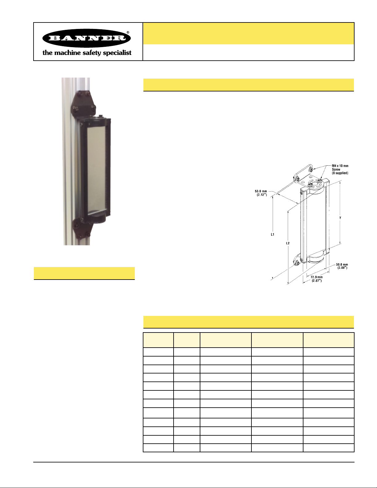
Mirror
Model
Part
Number
Reflective Area
Length (Y)
Mounting
Length (L1)
Mirror Height
Overall (L2)
MSM4A 43162
165 mm (6.5") 221 mm (8.7") 191 mm (7.5")
MSM8A 43163
267 mm (10.5") 323 mm (12.7") 292 mm (11.5")
MSM12A 43164
356 mm (14") 411 mm (16.2") 381 mm (15")
MSM16A 43165
457 mm (18") 513 mm (20.2") 483 mm(19")
MSM20A 43166
559 mm (22") 615 mm (24.2")
MSM24A 43167
660 mm (26") 716 mm (28.2") 686 mm (27")
MSM28A 43168
762 mm (30") 818 mm (32.2") 787 mm (31")
MSM32A 43169
864 mm (34") 919 mm (36.2") 889 mm (35")
MSM36A 43170
965 mm (38") 1021 mm (40.2") 991 mm (39")
MSM40A 43171
1067 mm (42") 1123 mm (44.2") 1092 mm (43")
MSM44A 43172 1168 mm (46") 1224 mm (48.2") 1194 mm (47")
MSM48A 43173
1270 mm (50") 1326 mm (52.2") 1295 mm (51")
Note: The mounting brackets may be
inverted from the positions shown
at right (flanges pointing “inward”
instead of “outward,” as shown).
When this is done, dimension L1
decreases by 56.9 mm (2.24"), and
rotation decreases to ± 45°.
584 mm (23")
Page 2
MSM Series Corner Mirrors
page
2
Banner Engineering Corp. • Minneapolis, U.S.A.
www.bannerengineering.com • Tel: 763.544.3164
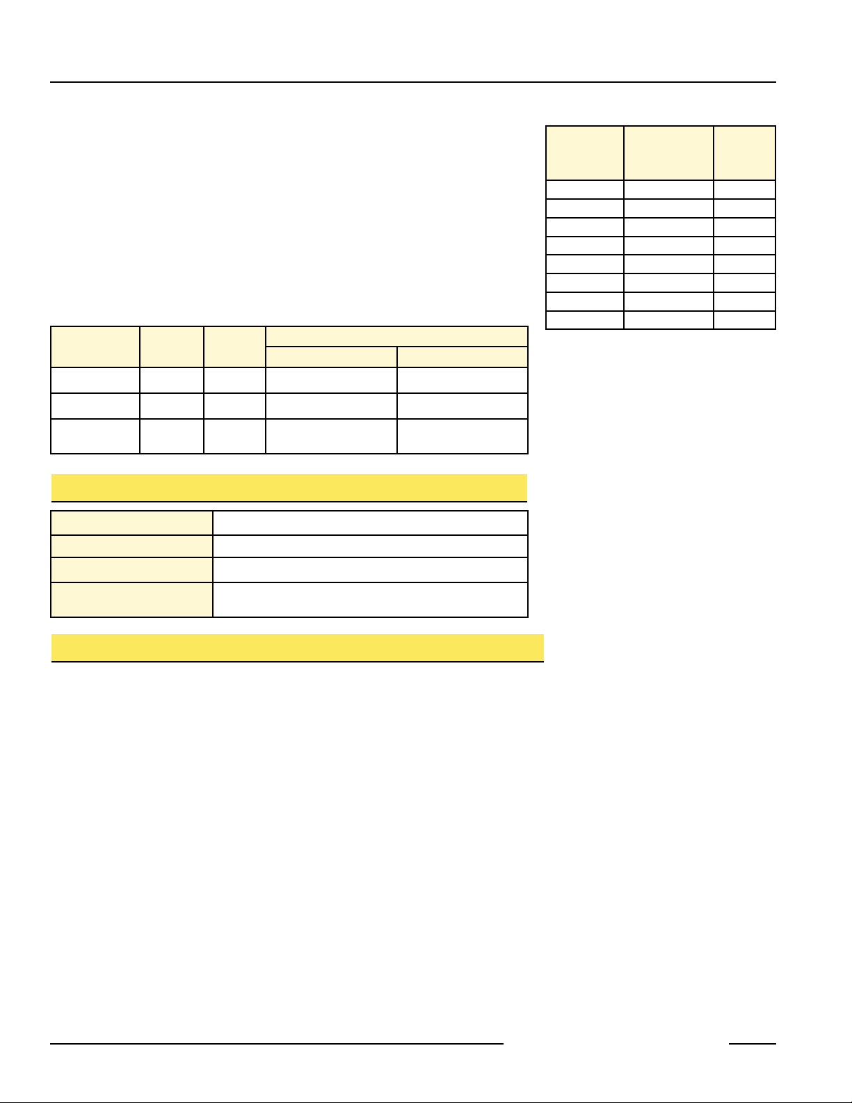
MSM Series mirrors may also be used with light screen sensors up to 48" long. The
table at right, recommends which mirror to use with the applicable sensors.
Each mirror is supplied with two mounting brackets and associated hardware (see
dimension drawing).
Mirrors should be securely mounted to a solid surface that is free from vibration.
Mirrors must be mounted parallel to their sensors, with the midpoint of the mirror(s)
directly in line with the midpoint of the sensor’s defined area.
MSA Series stands may be used to mount MSM Series mirrors. These stands offer an
extruded channel design for convenient mirror (or sensor) height adjustment. See
data sheet P/N 43687 for complete information. Several stand heights are available:
Light Screen
Defined Area
Length Up To
Recommended
Mirror Model
Reflective
Area
Length
8.5" MSM8A 10.5"
12" MSM12A 14"
18" MSM20A 22"
24" MSM24A 26"
30" MSM32A 34"
36" MSM36A 38"
42" MSM44A 46"
48" MSM48A 50"
Stand
Model
Part
Number
Stand
Height
Mirror Length
MSA-S24-1 43174 24" 4" to 8" 4" to 12"
MSA-S42-1 43175 42" 4" to 24" 4" to 28"
MSA-S66-1 43176 66" 4" to 48" 4" to 48"
Mirror Safety glass; rear-surface mirror
Mirror Frame Molded ABS end caps; rigid PVC sides
Bracket Cold-rolled steel; black zinc chromate finish
Routine Maintenance
Mirrors should be cleaned with a mild glass cleaning solution
and a soft cloth
MSM Series Construction
Brackets Outward Brackets Inward
Alignment of Sensors and Corner Mirrors
Mount the mirror(s) and the sensors so that they are all parallel. Use a level, if possible.
Adjust the position of the sensors and the mirror(s) so that the midpoint of the mirror(s)
and the sensors’ defined areas are even. (A line connecting the midpoint of all
components is illustrated by the dashed line in the drawing.) The midpoint of the defined
area of a MICRO-SCREEN sensor is the midpoint of the window. The upper and lower
limits of the defined area of MINI-SCREEN sensors is marked by arrows along the edge
of each sensor window, and is dimensioned in the appropriate instruction manual. The
midpoint of the defined area of MACHINE-GUARD/PERIMETER-GUARD sensors
corresponds to the midpoint of the sensor length.
Adjust the corner mirror(s) so that the angle of incidence to the mirrors equals the angle
of reflection from the mirror. Sight from behind one of the sensors directly towards the
mirror (or the first mirror in line). When alignment is correct, you will see the straight
and centered reflection of the lens of the other sensor in the mirror.
Use the alignment indicator(s) of the safety light screen system (and the appropriate
instruction manual) for final alignment.
Page 3

page 3
MSM Series Corner Mirrors
Banner Engineering Corp. •
Minneapolis, U.S.A.
www.bannerengineering.com • Tel: 763.544.3164
Corner Mirror Alignment
Range Reduction Using MSM Series Corner Mirrors
Use of corner mirrors reduces light screen range (the maximum separation between
the emitter and receiver). The following table lists the resultant range when using
from one to four MSM Series corner mirrors in the sensing path.
Light Screen
Sensors
0
Mirrors1Mirror2Mirrors3Mirrors4Mirrors
MICRO-SCREEN
V-Series
6 m
(20')
5.6 m
(18.4')
5.2 m
(17.0')
4.8 m
(15.7')
4.4 m
(14.5')
MICRO-SCREEN
Standard Series
9 m
(30')
8.5 m
(28')
7.8 m
(25.5')
7.2 m
(23.5')
6.7 m
(22')
MINI-SCREEN
Standard Series
9 m
(30')
8.5 m
(28')
7.8 m
(25.5')
7.2 m
(23.5')
6.7 m
(22')
MINI-SCREEN
XL-Series
18 m
(60')
16.8 m
(55')
15.5 m
(51')
14.3 m
(47')
13.1 m
(43')
MACHINE-GUARD/
PERIMETER-GUARD
14 m
(45')
12.6 m
(41.5')
11.6 m
(38')
10.7 m
(35')
9.9 m
(32.5')
Light Screen Maximum Range
Maximized excess gain is always important when installing a safety light screen. Use
hard guarding whenever possible to reduce the overall sensing range and the number
of mirrors required. Also, keep sensor lenses and mirrors clean and properly aligned.
Page 4

Banner Engineering Corp., 9714 Tenth Ave. No., Minneapolis, MN 55441 • Phone: 763.544.3164 • www.bannerengineering.com • E-mail: sensors@baneng.com
MSM Series Corner Mirrors
WARRANTY: Banner Engineering Corp. warrants its products to be free from defects for one year. Banner Engineering Corp. will repair or
replace, free of charge, any product of its manufacture found to be defective at the time it is returned to the factory during the warranty
period. This warranty does not cover damage or liability for the improper application of Banner products. This warranty is in lieu of any
other warranty either expressed or implied.
Maximum
Excess
Gain
Required
Operating
Environment
1.5x
Clean air: no dirt buildup on
lenses or mirrors
5x
Slightly dirty: slight buildup
of dust, dirt, oil, moisture,
etc. on lenses or mirrors.
Lenses and mirrors cleaned
on a regular schedule.
10x
Moderately dirty: obvious
contamination on lenses or
mirrors (but not obscured).
Lenses and mirrors cleaned
occasionally or when
necessary.
50x
Very dirty: heavy
contamination on lenses and
mirrors. Heavy fog, mist,
dust, smoke, or oil film.
Minimal cleaning of lenses
and mirrors.
Guidelines for Excess Gain ValuesExcess Gain
Given the range from the above chart, excess gain can be calculated for any distance
by using the inverse square law. For example, the excess gain for a 30' range MINISCREEN system at a 10' separation, using two corner mirrors, is calculated as
follows:
E.G.
= (25.5')2= 6.5 E.G. = (1x) (6.5) = 6.5x
1x (10')
2
For the same situation at a 10' separation, using MACHINE-GUARD sensors:
E.G. = (38')2= 14.4 E.G. = (3x) (14.4) = 43x
3x* (10')
2
*Note: MACHINE-GUARD sensor range is the separation between emitter and receiver
where 3x excess gain remains.
 Loading...