

Page 1
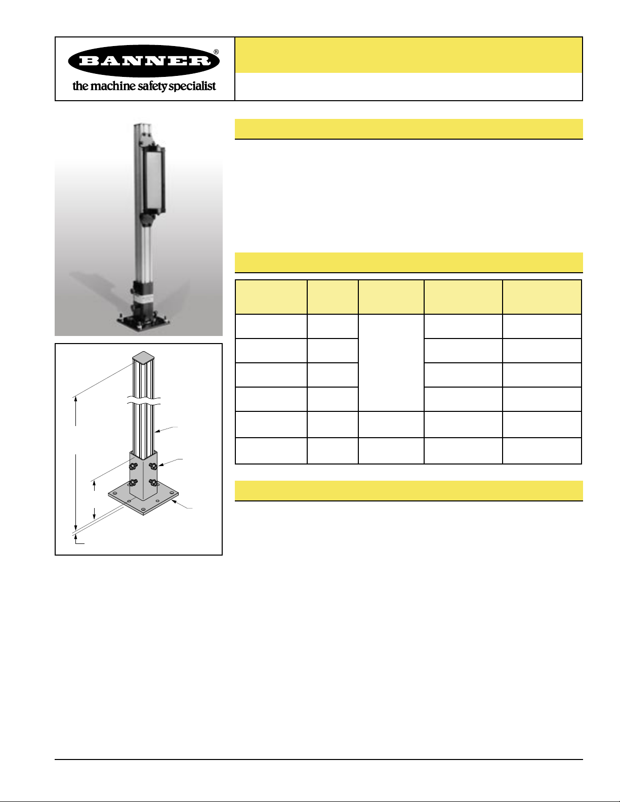
MSA Series Stands
(4) M10 Bolt
Pole
40 mm
(1.58") Square
Height L
(see Models
table)
Base
6.4 mm (0.25")
127 mm
(5")
For Optical Safety System Sensors or Corner Mirrors
Features
• Easy to assemble
• Available in four pole heights
• Solidly supports emitter, receiver or corner mirror
• Strong extruded and anodized aluminum poles
• Dual-channel design for accurate sensor/mirror adjustment
Models
Figure 1. Assembled stand
Model
MSA-S24-1
MSA-S42-1
MSA-S66-1
MSA-S84-1
SPKA-AG12-1
SPKA-AG30-1
Part
Number
43174
43175 42" 37"
43176 66" 61"
52397 84" 79"
73229
73230
For Use
With
Light Screens
and Mirrors as
Noted Below
SFP12
Safety Point
SFP30
Safety Point
Height “L”
(Figure 1)
24" 19"
42" 37"
42" 37"
Useable Stand
Height
Overview
Banner MSA Series stands are designed specifically for use with Banner optical safety
system emitters and receivers, and corner mirrors. The poles are constructed of strong,
lightweight extruded aluminum, and have a dual-channel design that allows easy and
accurate height adjustment using the supplied “T” nuts.
Each stand includes two major parts:
1. A welded steel base, and
2. An aluminum pole; 24", 42", 66", or 84" in length.
Hardware is included for attaching either a MICRO-SCREEN® or MINI-SCREEN®
sensor, an SFP.. Safety Point, or a corner mirror to the pole. (EZ-SCREEN™ or
MACHINE-GUARD™ sensors, and SSM-Series mirrors require an adapter bracket; refer
to the appropriate data sheet.) A post level also is included with each stand for accurate
installation.
The pole is held securely in its base by four bolts (included). The base bolts to a flat
surface with user-supplied 5/16" or M8 hardware. The base plate has four threaded
holes for leveling bolts (also included, see Figure 2).
Figures 3, 4 and 5 detail how a sensor or mirror attaches to the post using the supplied
hardware. This mounting design allows the sensor or mirror to easily slide up or down
the pole and then lock into position by tightening four screws.
Printed in USA 10/04 P/N 43687 rev. C
Page 2
MSA Series Stands
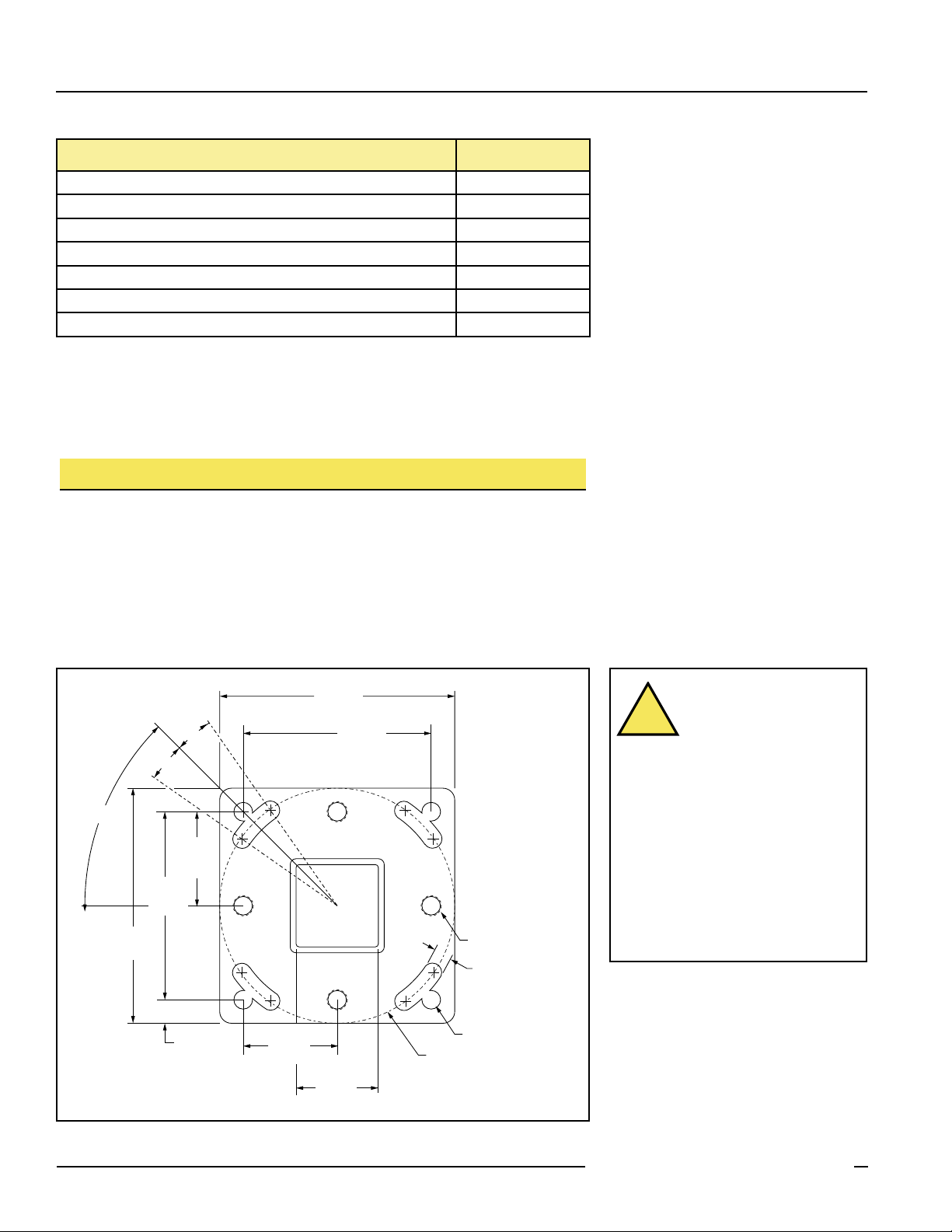
127 mm
(5.0")
127 mm
(5.0")
102 mm
(4.0")
51 mm
(2.0")
44.5 mm
(1.75")
Square
51 mm
(2.0")
10º
10º
45º
13 mm
(0.5")
ø127 mm (5.0")
102 mm
(4.0")
4x 0.397"
4x 0.397"
4x M10 x 1.0
!
Included with Each MSA Series Stand Quantity
Clear anodized extruded aluminum pole 1
Black epoxy-painted welded steel base assembly 1
Post level 1
Black zinc-plated steel adapter plate 2
M10 x 1 x 18 mm-long slotted/Phillips hex head bolt 4
M4 x 0.7 x 10 mm-long slotted hex head screw 12*
M4 “T” nut 8*
* Extra screws and T-nuts are included to accommodate mounting of center bracket used
with longer MICRO-SCREEN® Sensors.
NOTE: Adapter bracket EZA-MBK-2 is required for mounting EZ-SCREEN™ or MACHINE-
GUARD™ sensors, or SSM-Series mirrors. Refer to the data sheets for those products
for more information.
Installation of Base and Pole
1) Refer to Figure 2. The base is secured to the floor or other flat surface using
5/16" or M8 hardware, supplied by the installer. Place the base on its mounting
hardware, but do not tighten. Install an M10 leveling bolt (supplied) into each of
the four threaded holes for leveling purposes.
2) Using the post level (supplied), adjust the leveling bolts for true vertical level.
Continue to check the vertical level of each pole while tightening the base
mounting hardware.
WARNING . . .
Maintain Required
Separation Distance
The light screen produced
by the optical safety system sensors
must be placed at a minimum safe
distance from the dangerous motion
of the machine being guarded. This
necessary minimum distance is called the
separation distance, and is discussed in
Section 3 of the appropriate instruction
manuals. Failure to calculate this
distance correctly and to maintain
minimum separation distance can result
in serious injury or death.
Figure 2. Stand base mounting hole pattern
2 P/N 43687 rev. C
Banner Engineering Corp. • Minneapolis, MN U.S.A.
www.bannerengineering.com • Tel: 763.544.3164
Page 3

Stand Pole
Bracket
(2 supplied with sensor)
2x M3 Screw
(supplied with sensor)
M4 Screw and "T" Nut
(8 supplied with stand; use as needed)
MICRO-SCREEN
(emitter/receiver)
Figure 3. Sensor-to-stand mounting for MICRO-SCREEN sensor
MSA Series Stands
Mounting Sensor or Mirror to Pole
1) Verify that all poles used for the light screen installation are
exactly parallel to each other before mounting sensors and/
or mirrors.
2) Refer to Figures 3, 4, 5, 6, and 7. Assemble the brackets and
hardware as shown in the appropriate figure.
3) Loosely mount the bracket assemblies (see step 2, above) to
the pole using the M4 screws and “T” nuts supplied with the
stand†.
Note that Figures 3, 4 and 5 show the bracket assembly
pointed “outward” (away from the sensor or mirror). One
or both of the bracket assemblies may be reversed to point
“inward,” if necessary. However, access to the mounting
screws becomes less convenient and mirror rotation is
limited when a bracket assembly is pointed inward.
Figure 4. Sensor-to-stand mounting for MINI-SCREEN sensor
Figure 5. Mirror-to-stand mounting for MSM Series mirror
Figure 6. Adapter bracket-to-stand mounting, shown ready for
mounting of EZ-SCREEN or MACHINE-GUARD sensor or
SSM-Series mirror
4) Mount the sensor or mirror to its brackets using the screws
supplied with the sensor or mirror. Temporarily tighten those
screws. (NOTE: MICRO-SCREEN sensors from 40" to 48"
long also include one center bracket, and MICRO-SCREEN
sensors from 52" to 72" long include two center brackets.
M4 and “T” nuts are provided with the stands for these
situations. See the MICRO-SCREEN installation manual for
further details.)
5) Slide the sensor or mirror into position along the length of
the pole and tighten the M4 screws into their “T” nuts to lock
the sensor or mirror into position.
IMPORTANT: Step 5 requires accuracy. If no mirrors are
involved in the sensing path, then any feature of the emitter
can be matched in vertical position with the same feature on
the receiver. However, if one or more mirrors is used, the
center of each mirror must match the vertical position of
the center of the defined area of the sensors. The upper and
lower limits of the defined area are dimensioned in the light
screen instruction manual.
6) Loosen the bracket screws (tightened in Step 4) to allow the
sensor or mirror to rotate for alignment. See the light screen
instruction manual for alignment information.
Figure 7. Swivel bracket-to-stand mounting for SFP12 or
Banner Engineering Corp. • Minneapolis, MN U.S.A.
www.bannerengineering.com • Tel: 763.544.3164
P/N 43687 rev. C 3
SFP30 Point
Page 4

MSA Series Stands
WARRANTY: Banner Engineering Corp. warrants its products to be free from defects for one year. Banner Engineering Corp. will repair
or replace, free of charge, any product of its manufacture found to be defective at the time it is returned to the factory during the warranty
period. This warranty does not cover damage or liability for the improper application of Banner products. This warranty is in lieu of any
other warranty either expressed or implied.
P/N 43687 rev. C
Banner Engineering Corp., 9714 Tenth Ave. No., Minneapolis, MN USA 55441 • Phone: 763.544.3164 • www.bannerengineering.com • Email: sensors@bannerengineering.com
 Loading...