

Page 1
Muting Module
Models MMD-TA-11B and MMD-TA-12B
Features
• Compact, 67.5 mm DIN-mounted housing with
plug-in terminal blocks.
Instruction Manual
• For use with EZ-SCREEN
Device (OSSD) outputs or MINI-SCREEN®, MICROSCREEN®, MACHINE-GUARD®, or other safety
devices with hard relay contact safety output(s) or
+24V dc (PNP) outputs.
• Monitors two or four inputs to automatically suspend
the safety function of a safeguarding device.
• Can be used as a dual controller when muting
function is not used.
• Safety (protective) Stop Interface (SSI) for connection
of supplemental safeguarding devices, E-stops, or
other devices.
• Category 2, 3, or 4 hookup per ISO 13849-1/-2.
• Selectable external device monitoring (EDM).
• Selectable Automatic or Monitored Manual Reset
provides flexibility for point-of-operation, area, or
perimeter guarding.
•
Two N.O. safety contacts (model MMD-TA-11B) or
diverse-redundant solid-state safety outputs (model
MMD-TA-12B).
• Status LEDs and two-digit Diagnostic Display indicate
module status.
• Easy configuration for:
Auto/manual reset
One-/two-channel EDM
One-/two-direction muting
Selectable mute enable
Monitored/non-monitored mute lamp
Selectable backdoor timer
Selectable mute on power-up
®
Output Signal Switching
Section Contents
Section 1 Introduction . . . . . . . . . . . . . . . . . . . . . . . . . . . . . . . . . . . . . Page 1
Section 2 Components and Specifications
Section 3 System Installation
Section 4 Operating Instructions
Section 5 Troubleshooting and Maintenance
Section 6 Checkout Procedures
Appendix
. . . . . . . . . . . . . . . . . . . . . . . . . . . . . . . . . . . . . . . Page 45
. . . . . . . . . . . . . . . . . . . . . . . . . . . . . . . Page 12
. . . . . . . . . . . . . . . . . . . . . . . . . . . . . Page 39
. . . . . . . . . . . . . . . . . . . . . . . . . . . . . Page 42
. . . . . . . . . . . . . . . . . . . . . Page 8
. . . . . . . . . . . . . . . . . . . Page 40
Printed in USA 08/07 P/N 116390 rev. C
Page 2

Table of Contents
MMD-TA-11B / MMD-TA-12B Muting Module
Instruction Manual
Important ...
read this before proceeding!
In the United States, the functions that the
Banner MMD-TA-11B and MMD-TA-12B
Muting Modules are intended to perform are
regulated by the Occupational Safety and
Health Administration (OSHA). Outside of the
United States, these functions are regulated
by a variety of agencies, organizations, and
governments. Whether or not any particular
Muting Module installation meets all applicable
requirements depends upon factors that are
beyond the control of Banner Engineering
Corp. These factors include the details of
how the Muting Module is applied, installed,
wired, operated, and maintained. It is the
responsibility of the installer and user to
apply this Muting Module in full compliance
with all applicable regulations and
standards.
The Muting Module can guard against
accidents only when it is properly installed
and integrated into the machine, properly
operated, and properly maintained. Banner
Engineering Corp. has attempted to provide
complete application, installation, operation,
and maintenance instructions. In addition,
we suggest that any questions regarding
application or use of this Muting Module be
directed to the factory applications department
at the telephone number or addresses shown
on the back cover.
In addition to OSHA regulations, several other
organizations provide information about the
use of safeguarding devices. Refer to the
American National Standards Institute (ANSI),
the Robotics Industries Association (RIA), the
Association for Manufacturing Technology
(AMT), and others. Banner Engineering
Corp. makes no claim regarding a specific
recommendation of any organization, the
accuracy or effectiveness of any information
provided, or the appropriateness of the
provided information for a specific application.
See inside back cover for information
pertaining to applicable U.S., European,
and International standards and where to
acquire copies.
The user has the responsibility to ensure
that all local, state, and national laws, rules,
codes, and regulations relating to the use of
this safeguarding system in any particular
application are satisfied. Extreme care is urged
to ensure that all legal requirements have been
met and that all installation and maintenance
instructions contained in this manual are
followed.
Table of Contents
1. Overview ....................................................................................................... page 1
1.1 Introduction .............................................................................................page 1
1.2 Operating Status LEDs and Diagnostic Display .................................... page 2
1.3 Automatic or Monitored Manual Reset Select ....................................... page 3
1.4 Lockout Conditions ................................................................................ page 3
1.5 Control Reliability: Redundancy and Self-Checking .............................. page 3
1.6 Muteable Safety Stop Interface (MSSI) ................................................. page 4
1.7 Safety Stop Interface (SSI) .....................................................................page 4
1.8 OSSD Outputs ....................................................................................... page 4
1.9 Auxiliary Output (Aux) .............................................................................page 4
1.10 External Device Monitoring (EDM) .........................................................page 4
1.11 Mute Inputs (M1-M4) and Mute Devices ................................................page 5
1.12 Mute Enable (ME) ...................................................................................page 5
1.13 Mute Lamp Output (ML) .........................................................................page 6
1.14 Backdoor Timer .......................................................................................page 6
1.15 Mute on Power-Up ..................................................................................page 6
1.16 Override ..................................................................................................page 7
1.17 One-Way/Two-Way Muting .....................................................................page 7
1.18 Designated and Qualified Persons ......................................................... page 7
2. Components and Specifications ........................................................................ page 8
2.1 Specifications ..........................................................................................page 8
2.2 Accessories ......................................................................................... page 11
2.3 Dimensions ...........................................................................................page 11
3. System Installation ............................................................................................ page 12
3.1 Appropriate Application ........................................................................ page 12
3.2 Installing the Module ............................................................................ page 14
3.3 Muting Module Configuration ............................................................... page 15
3.4 Connection Terminals/Functions ......................................................... page 16
3.5 Installing Input Devices ......................................................................... page 17
3.6 Machine Interface – Initial Hookup and Checkout ............................. page 30
3.7 Permanent Hookup to the Guarded Machine...................................... page 31
3.8 Commissioning Checkout .................................................................... page 34
4. Operating Instructions ...................................................................................... page 39
4.1 Security Protocol ................................................................................. page 39
4.2 Periodic Checkout Requirements ........................................................ page 39
4.3 Normal Operation ................................................................................. page 39
5. Troubleshooting and Maintenance ..................................................................
5.1 Troubleshooting Lockout Conditions ................................................... page 40
5.2 Diagnostic Display ................................................................................page 40
5.3 Effects of Electrical Noise ................................................................... page 40
5.4 Repairs ................................................................................................. page 40
6. Periodic Checkout Procedures ........................................................................ page 42
6.1 Schedule of Checkouts ......................................................................... page 42
6.2 Commissioning Checkout ................................................................... page 42
6.3 Daily Checkout ......................................................................................page 44
6.4 Semi-Annual Checkout .......................................................................
Appendix
Appendix A, Mute Timing Sequences ................................................................. page 45
Appendix B, Typical Muting Applications ............................................................page 46
Glossary of Terms ..................................................................................................page 52
page 40
page 44
Banner Engineering Corp. • Minneapolis, U.S.A.
www.bannerengineering.com • Tel: 763.544.3164
Page 3
MMD-TA-11B / MMD-TA-12B Muting Module
MMD-TA-..
Muting Module
Safety Light
Screen Control
CH B
+24V dc
0V dc
OSSD1*
OSSD2*
EDM1
EDM2
Mute
Enable
CH A
MSSI
Machine
Interface
Mute Devices
M1, M2, M3, M4
SSI
AUX*Override Reset
+24V dc
0V dc
GND
FSD2/OSSD2
FSD1/OSSD1
Safety Light Screen
Defined Area
Mute
Lamp
* Model MMD-TA-11B: These are relay contact outputs
Model MMD-TA-12B: This is a solid-state output
Instruction Manual
1. Overview
1.1 Introduction
Overview
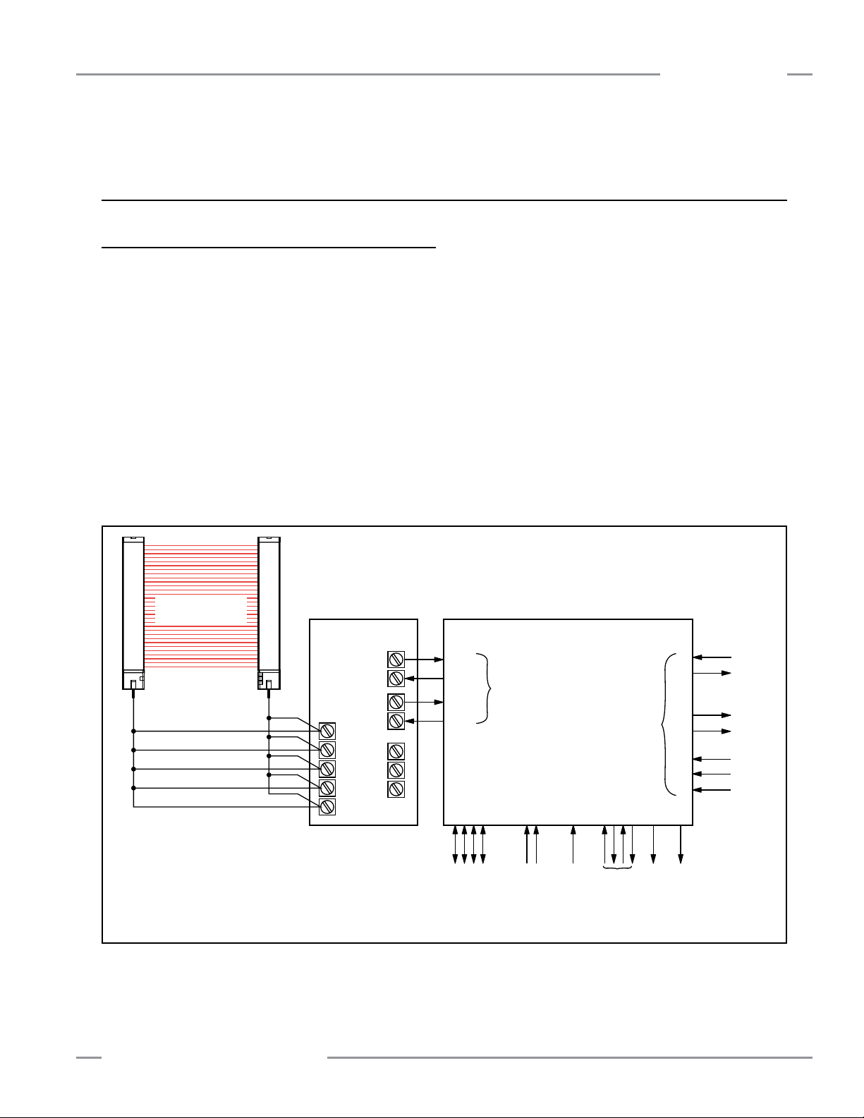
The Banner MMD-TA-11B / MMD-TA-12B Muting Module (the
Module) is an accessory component of a safeguarding system,
which may incorporate such primary safeguards as safety light
screens, safety interlocked gates/guards, or other presencesensing safeguarding devices (PSSDs). The Module allows the
machine to mute the primary safeguard by monitoring redundant
inputs (two or four) and automatically suspend the safeguarding
function of a safeguarding device during the non-hazardous
portion of the machine cycle.
In this manual, the term “muting” refers to the automatic
suspension of the safeguarding function of the primary safety
device during a non-hazardous portion of the machine cycle
where personnel are not exposed to harm.
The muting function allows material to be manually or
automatically fed into or removed from a machine process,
without tripping the primary safeguard. The Module accomplishes
this by using diverse-redundant microprocessors that monitor the
status of inputs and outputs, so that a single fault will cause the
Module to issue a stop command to the machine. The Module,
like all Banner safety products, is extensively FMEA (Failure
Mode and Effects Analysis) tested to establish an extremely high
degree of confidence that no internal component will, even if it
does fail, cause a failure to danger. This design philosophy aids
machine designers to comply with U.S. control reliability and
worldwide standards for the highest level of safety.
Figure 1-1. Block diagram of a safeguarding system employing the Muting Module and a safety light screen (user-supplied) as a
Banner Engineering Corp. • Minneapolis, U.S.A.
www.bannerengineering.com • Tel: 763.544.3164
primary safety device
P/N 116390 rev. C 1
Page 4
Overview
MMD-TA-11B / MMD-TA-12B Muting Module
Instruction Manual
Individual features discussed in the following sections are:
- Operating Status LEDs and Diagnostic Display
- Auto/manual reset
- Lockout conditions
- Control reliability
- Mutable Safety Stop Interface (MSSI)
- Safety Stop Interface (SSI)
- Output Signal Switching Device (OSSD) outputs
- Auxiliary (AUX) output
- External device monitoring (EDM)
- Mute devices and mute inputs (M1−M4)
- Mute enable input (ME)
- Mute lamp output (ML)
- Backdoor timer
- Mute on power-up
- Override
- One-way/two-way muting
Safety Stop Inputs (SSI)
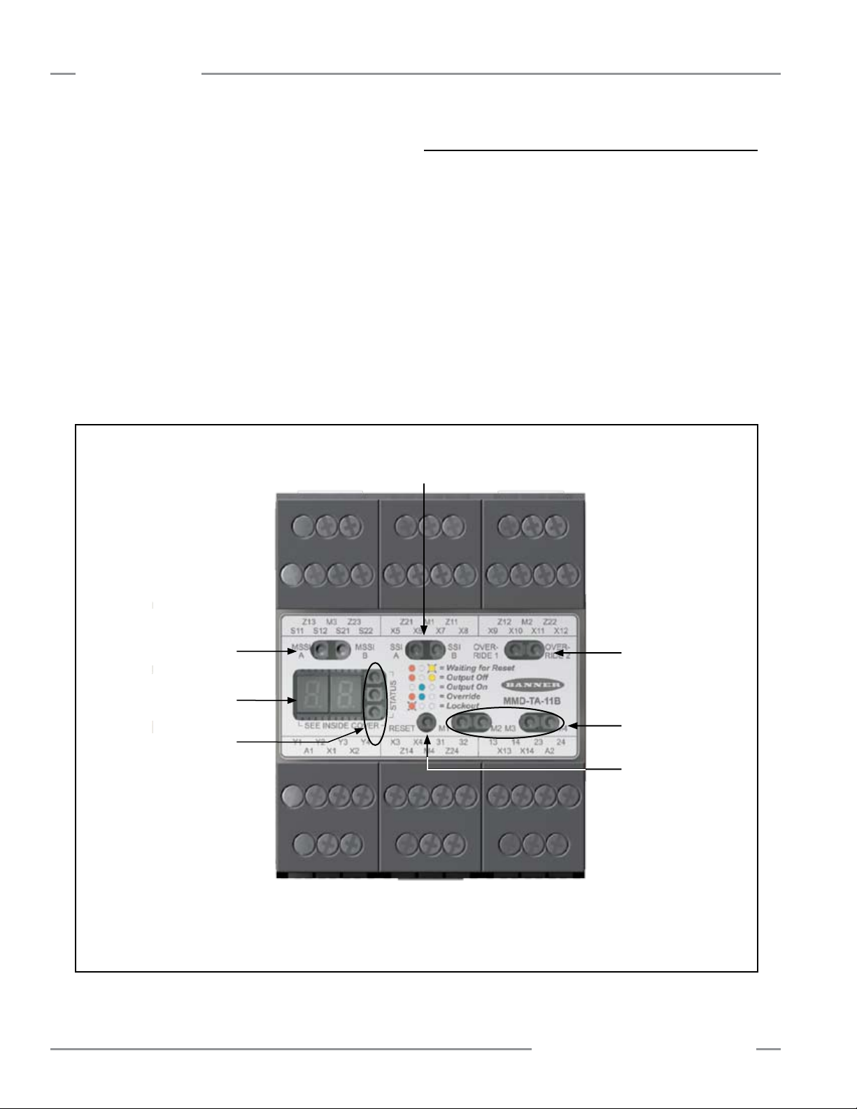
1.2 Operating Status LEDs and Diagnostic Display
The Module has three Operating Status LEDs (one each red,
yellow and green), plus a 2-digit Diagnostic Display, visible
through a window in the front cover. The individual LEDs provide
constant, ongoing system status information at a glance. The
Diagnostic Display provides error codes that correspond to the
cause of a fault or configuration error which results in a lockout,
and other more detailed conditions. See Sections 4 and 5 for
further information.
Active LEDs (green)
Muteable Safety Stop
Input(s) (MSSI)
Active LEDs (green)
2-Digit
Diagnostic Display
Red, Green,
Yellow Status
LEDs
NOTE: A green or yellow indicator is provided for each input to verify an active state. A green indicator is provided for the
Reset Input and for MSSI and SSI inputs. A yellow indicator is provided for each of the mute device (M1–M4) and
OVERRIDE inputs.
Figure 1-2. Muting Module features
Override Active LEDs
(yellow)
Muting Devices
Status LEDs (yellow)
Reset Input
(green)
2 P/N 116390 rev. C
Banner Engineering Corp. • Minneapolis, U.S.A.
www.bannerengineering.com • Tel: 763.544.3164
Page 5

MMD-TA-11B / MMD-TA-12B Muting Module
Instruction Manual
Overview
1.3 Automatic or Monitored Manual Reset Select
The selectable Automatic or Monitored Manual Reset (X1−X2)
provides flexibility for the user who has applications in which
the operator is continually sensed, or in applications where the
operator can pass through and become clear of the sensing
field (see Section 3.1.4, “Pass-Through Hazards”) or other
applications requiring a manual reset.
The configuration is selected via two banks of DIP switches
located under the Module’s front cover (see Figures 1-2 and
3-2).
Monitored Manual Reset
Manual Reset is typically used in situations where the individual
can pass through a sensing field and become clear of a
safeguarding device, such that the device can no longer prevent
hazardous motion (e.g., perimeter guarding). The Module
“monitors” the input for two transitions: from open-to-closed, and
from closed-to-open within a certain time period. This prevents
the reset button from being tied down or failing in a closed
condition, and causing an unintended or automatic reset.
Upon power-up, when the Module has been configured for
manual reset, for the OSSD outputs to turn ON, both the MSSI
and the SSI must be active (closed) and a monitored manual
reset must be accomplished. The reset is accomplished by
closing the Reset input for a minimum of 1/4 second, but not
longer than 2 seconds and then re-opening the input. The OSSD
outputs will turn ON once the open-closed-open action occurs.
In this configuration, the Module must be manually reset after
power-up, lockouts, and after the cycling of either the MSSI (not
muted) or the SSI. The location for the manual reset device
(e.g., a normally open key switch) must comply with the warning
in Section 3.5.1 and refer to that section for further information
on key resets.
1.4 Lockout Conditions
A lockout condition of the Module will cause both OSSD outputs
to go OFF. A lockout condition is indicated by a flashing Red
status indicator and an error number displayed on the Diagnostic
Display.
A description of possible lockouts, their causes, troubleshooting
hints, and a Manual Reset routine are listed in Section 5.
1.5 Control Reliability: Redundancy and Self-Checking
Redundancy requires that Module circuit components be
“backed up” to the extent that, if the failure of a single
component will prevent effective machine stopping action when
needed, that component must have a redundant counterpart
which will perform the same function. The microprocessorcontrolled Muting Module is designed with diverse redundancy.
Diverse-redundant components are of different designs, and
microprocessor programs used by them run from different
instruction sets.
Redundancy must be maintained for as long as the Muting
Module is in operation. Since a redundant system is no longer
redundant once a component has failed, the Module is designed
to be continuously self-checking. A component failure detected
by or within the self-checking system causes a “stop” signal
to be sent to the guarded machine and puts the Module into a
lockout condition.
Recovery from this type of lockout condition requires
replacement of the failed component (to restore redundancy) and
the appropriate reset procedure (see Section 3.5.1). Possible
causes are listed in Section 5. The Diagnostic Display is used to
diagnose causes of a lockout condition (Section 5).
Automatic Reset
Upon power-up, when the Module is configured for automatic
reset, the OSSD outputs will automatically turn ON once power
is applied, the self-test is accomplished, and the MSSI and the
SSI are active (closed). The OSSD outputs will also turn ON
after either interface is de-activated and then re-activated. In
either case, no external input or reset is required.
Automatic reset is typically used in situations where the
individual is continually sensed by the defined area or in
situations where supplemental safeguards prevent the initiation
of hazardous motion while an individual is within the safeguarded
space (e.g., point-of-operation guarding).
In either case, a manual reset must be performed to recover
from a lockout condition.
In Automatic Reset mode, input X1−X2 stays open.
Banner Engineering Corp. • Minneapolis, U.S.A.
www.bannerengineering.com • Tel: 763.544.3164
P/N 116390 rev. C 3
Page 6
Overview
MMD-TA-11B / MMD-TA-12B Muting Module
Instruction Manual
1.6 Muteable Safety Stop Interface (MSSI)
The Muteable Safety Stop Interface (MSSI) input (S11−S12,
S21−S22) is a specialized SSI that can be muted during the nonhazardous portion of the machine cycle.
The Module requires redundant input signals from the external
primary safeguard which is to be muted. These inputs typically
are either two Banner solid-state safety outputs or two monitored
forced-guided relay outputs from an appropriate safety device.
See Section 2, Specifications, and Section 3.5.6 for complete
information.
WARNING . . . Emergency Stop
Functions
Do not connect any Emergency Stop devices
to the MSSI Input; do not mute or bypass any Emergency
Stop device. ANSI NFPA79 and IEC/EN 60204-1 require
that the Emergency Stop function remain active at all times.
Muting or bypassing the safety outputs will render the
Emergency Stop function ineffective.
1.7 Safety (Protective) Stop Interface (SSI)
The Module has a provision for an additional Safety (Protective)
Stop Interface (X5−X6, X7−X8) to connect an optional device,
such as a supplemental safeguard, E-stop button, or safety
switch(es), to issue a stop command. This dual-channel interface
is similar to the MSSI, but is always functional, even when
the primary safety device is being muted. See Sections 2,
Specifications, and 3.5.6 for complete information.
1.8 OSSD Outputs
Model MMD-TA-12B has two solid-state safety outputs (Y5−Y6,
Y7−Y8); and model MMD-TA-11B has two normally open hardcontact safety outputs (13−14, 23−24), labeled “OSSD1” and
“OSSD2” (see Figure 1-1). The solid-state safety outputs are
actively monitored to detect short circuits to the supply voltage,
to each other, and to other sources of electrical energy. If a
failure is detected, the outputs will switch to an OFF-state. For
circuits requiring the highest level of safety and reliability, either
OSSD must be capable of stopping the motion of the guarded
machine in an emergency.
1.9 Auxiliary Output (Aux)
The Auxiliary (Aux) monitoring PNP (Z3−Z4) output on the
MMD-TA-12B and the parallel N.C. contact output on the -11B
are intended for non-safety related purposes. The status of
this auxiliary output is indicated by the green Status LED. See
Section 3.5.4 for more information.
1.10 External Device Monitoring (EDM)
Two inputs are provided (see Figures 3-24 to 3-28) for monitoring
the state of external devices, such as MPCEs. These terminals
are labeled “EDM1” (Y1−Y2) and “EDM2” (Y3−Y4). The Module’s
EDM inputs can be configured in three ways: one-channel, twochannel, or no monitoring (see Figure 3-2 for DIP switch settings
and Section 3.7.2 for external hookup). One- and two-channel
EDM are used when the OSSD outputs directly control the deenergizing of the MPCEs or external devices.
• One-Channel Monitoring: a series connection of closed
monitor contacts that are forced-guided (mechanically linked)
from each device controlled by the Muting Module. The monitor
contacts must be closed before the Module can be reset (either
Manual or Automatic). After a reset is executed and the safety
outputs (OSSDs) are closed, the status of the monitor contacts
is no longer monitored. However, the monitor contacts must be
closed within 200 milliseconds of the OSSD outputs going from
ON to OFF.
• Two-Channel Monitoring: an independent connection of
closed monitor contacts that are forced-guided (mechanically
linked) from each device controlled by the Muting Module. Both
EDM inputs must be closed before the Module can be reset and
the OSSDs can turn ON. While the OSSDs are ON, the inputs
may change state (either both open, or both closed). If the
inputs remain in opposite states for more than 200 milliseconds,
a lockout will occur. Additionally, both inputs must be closed
200 milliseconds after the OSSD outputs go OFF, or a lockout
will occur.
No Monitoring: If no monitoring is desired, the 1-ch/2-ch
•
selection switches must be configured for two-channel EDM,
and Y1 must be jumpered to Y3. If the Module is set for No
Monitoring, the user must ensure that any single failure of the
external devices does not result in a hazardous condition and
a successive machine cycle will be prevented (see Section 1.5,
Control Reliability).
During the muted portion of the machine cycle, the MSSI inputs
will be ignored and OSSD1 and OSSD2 will remain ON. During
other portions (not muted) of the cycle, if the MSSI either open
or go OFF, OSSD1 and OSSD2 will go OFF.
In any case, if the SSI interface opens, OSSD1 and OSSD2 will
go OFF. See Appendix A for timing diagrams.
4 P/N 116390 rev. C
Banner Engineering Corp. • Minneapolis, U.S.A.
www.bannerengineering.com • Tel: 763.544.3164
Page 7
MMD-TA-11B / MMD-TA-12B Muting Module
Instruction Manual
Overview
1.11 Mute Inputs (M1−M4) and Mute Devices
The Muting Function
To mute the primary safeguard appropriately, the design of a
muting system must:
1. Identify the non-hazardous portion of the machine cycle,
2. Involve the selection of the proper muting devices, and
3. Include proper mounting and installation of those devices.
The Module can monitor and respond to redundant signals that
initiate the mute (M1: Z11–Z21; M2: Z12–Z22; M3: Z13–Z23;
M4: Z14–Z24). The mute then suspends the safeguarding
function by ignoring the state of the MSSI. This allows a person
to interrupt the defined area to load and/or unload parts or
an object to pass through the defined area of a safety light
screen, without generating a stop command. (This should not be
confused with blanking, which disables one or more beams in a
safety light screen, resulting in larger resolution.) See Appendix
A for example mute timing sequences.
The mute may be triggered by a variety of external devices. This
feature provides a variety of options (see Sections 3.5.2 − 3.5.3)
to tailor the System to the requirements of a specific application.
A pair of muting devices must be triggered simultaneously (within
3 seconds of one another). This reduces the chance of common
mode failures or defeat.
WARNING . . . Muting Limitations
Muting is allowed only during the nonhazardous portion of the machine cycle.
A muting application must be designed so that no single
component failure can prevent the stop command or allow
subsequent machine cycles until the failure is corrected
(per OSHA 1910.217(c)(3)(iii)(d), and ANSI B11.19).
Mute Devices
The beginning and end of a mute cycle must be triggered by
outputs from either pair of muting devices, depending on the
application. The mute device pairs both must have normally
open contacts, or have one device with a PNP output and one
device with an NPN output, both of which fulfill the “muting
device requirements” in Sections 2 and 3.5.2. These contacts
must close (conduct) when the switch is actuated to initiate the
mute, and must open (non-conducting) when the switch is not
actuated and in a power-OFF condition.
The Module monitors the mute devices to verify that their outputs
turn ON within 3 seconds of each other. If the inputs do not meet
this simultaneity requirement, a mute condition can not occur.
Several types and combinations of mute devices can be used,
including, but not limited to: limit switches, photoelectric sensors,
positive-driven safety switches, inductive proximity sensors, and
“whisker” switches. (See Muting Device Requirements, Section
3.5.2.)
1.12 Mute Enable (ME)
The Mute Enable input (X13−X14) is a non-safety-rated input.
When the input is closed (terminals X13−X14 jumpered), the
Module will allow a mute condition to occur; opening this input
while the System is muted will have no effect. The Module
is factory-supplied with a jumper installed between terminals
X13−X14. To use the Mute Enable function, remove the jumper.
Typical uses for Mute Enable include:
• To allow the machine control logic to create a “window” for
muting to begin;
• To inhibit muting from occurring; or
• To reduce the chance of unauthorized or unintended
bypassing or defeat of the safety system.
WARNING . . . Mute Inputs Must Be
Redundant
It is not acceptable to use a single switch,
device, or relay with two N.O. contacts for the mute
inputs. This single device, with multiple outputs, may fail so
that the System is muted at an inappropriate time. This may
result in a hazardous situation.
Banner Engineering Corp. • Minneapolis, U.S.A.
www.bannerengineering.com • Tel: 763.544.3164
Simultaneity Timer Reset Function
The Mute Enable input can also be used to reset the simultaneity
timer of the mute inputs. If one input is active for longer than
three seconds before the second input becomes active, the
simultaneity timer will prevent a mute cycle from occurring. This
could be due to a normal stoppage of an assembly line that may
result in blocking one mute device and the simultaneity time
running out.
If the ME input is cycled (closed-open-closed) while one mute
input is active, the simultaneity timer is reset, and if the second
mute input becomes active within three seconds, a normal mute
cycle begins. The timing requirement for the closed-open-closed
is similar to the manual reset function. Initially, the input needs
to be active (closed) for longer than 1/4 second, then open for
longer than 1/4 second, but not longer than 2 seconds, and then
must reclose to reset the simultaneity timer. The function can
reset the timer only once per mute cycle (i.e., all mute inputs
M1−M4 must open before another reset can occur).
P/N 116390 rev. C 5
Page 8
Overview
MMD-TA-11B / MMD-TA-12B Muting Module
Instruction Manual
1.13 Mute Lamp Output (ML)
Some applications require that a lamp (or other means) be used
to indicate when the safety device (e.g., light screen) is muted;
the module provides for this (X3−X4; see Caution below). This
indication is selectable between a monitored or a non-monitored
output signal (NPN sinking). The monitored output will prevent
the initiation of a mute after an indicator failure is detected
(current draw falls below 10 mA or goes above 360 mA). If the
application requires compliance with UL 61496, Lamp Monitoring
must be selected and the lamp used must meet applicable
requirements (see Section 3.5.3).
CAUTION . . . Mute Status Must Be
Readily Observable
Indication that the safety device is muted
should be provided and be readily observable.
Failure of this indication should be detectable and prevent
the next mute, or the operation of the indicator should be
verified at suitable intervals.
Lamp Monitoring must be selected if the application requires
compliance with UL 61496.
1.14 Backdoor Timer
The Backdoor Timer allows the user to select a maximum
period of time that muting is allowed to occur. This feature
hinders the intentional defeat of the muting devices to initiate
an inappropriate mute. It is also useful for detecting a common
mode failure that would affect all mute devices in the application.
The timer begins when the second muting device makes the
simultaneity requirement (within 3 seconds of the first device),
and will allow a mute to continue for the predetermined time.
After the timer expires, the mute ends – no matter what the
signals from the mute devices indicate. If the MSSI is open,
the OSSD outputs will turn OFF and must be manually reset (if
Module is configured for Manual Reset). The Override function
can be activated (see Section 1.16) to force the OSSDs ON in
order to clear the obstruction.
If the Backdoor Timer expires, a #50 error code will be displayed
until all mute device inputs are open and the MSSI is active
(closed).
The Backdoor Timer can be disabled (i.e., set for infinite time).
See Figure 3-2 and configure DIP switches #7 and #8 for
Backdoor Time-Out OFF.
WARNING . . . Backdoor Timer
An infinite time for the backdoor timer (i.e.,
disabling) should be selected only if the
possibility of an inappropriate or unintended mute cycle is
minimized, as determined and allowed by the machine’s risk
assessment. It is the user’s responsibility to ensure that this
does not create a hazardous situation.
1.15 Mute on Power-Up
Mute Enable must be closed to allow Mute on Power-Up. (See
Warning below.) If selected, the Mute on Power-Up function will
initiate a mute when power is applied, the Mute Enable input is
closed, the MSSI inputs are active (closed), and either M1−M2 or
M3−M4 (but not all four) are closed.
If Auto Reset is configured, the Module allows 10 seconds for
the MSSI and SSI to become active (closed) to accommodate
systems that may not be immediately active at power-up.
If Manual Reset is configured, the first valid reset after the MSSI
and SSI are active (closed) will result in a mute cycle if all other
conditions are satisfied.
WARNING . . . Mute on Power-Up
The Mute on Power-Up function should be
used only in applications where:
• Muting the System (M1 and M2 closed) when power is
applied is required, and
• Using it must not, in any situation, expose personnel to
any hazard.
6 P/N 116390 rev. C
Banner Engineering Corp. • Minneapolis, U.S.A.
www.bannerengineering.com • Tel: 763.544.3164
Page 9
MMD-TA-11B / MMD-TA-12B Muting Module
Instruction Manual
Overview
1.16 Override
The Override function (X9−X10, X11−X12) allows the user to
manually force the OSSD outputs ON for up to 30 seconds in a
situation such as an object becoming “stuck” in the defined area
of a safety light screen after the mute ends (e.g., a car body on
a transfer line entering a work cell). The feature is intended to
allow the user to “jog” the part out of the defined area. The need
to perform an Override is indicated by a flashing mute lamp.
This input requires two normally open switches, both of which
must be closed within 3 seconds of each other. The Override
cycle will last a maximum of 30 seconds, after which the
Override input must be released for at least 0.5 seconds prior
to the next Override cycle. An Override can be initiated only
after tripping of the MSSI inputs causes the Module to latch its
OSSDs OFF.
NOTE: A stop command issued by the SSI cannot be overridden.
When Override is used, the following precautions must be taken:
- Prevent exposure to any hazard during an Override cycle,
- Provide a readily observable indication of an Override, and
- Provide supplemental safeguarding, per ANSI NFPA79 and
IEC/EN60204-1.
The Override switches must be supervised and must prevent
automatic operation. Also, one or more of the following must be
true:
- Motion is initiated by a hold-to-run or similar device,
- If a portable control station (e.g., an enabling device) with an
emergency stop device is used, motion may be initiated only
from that station,
- Motion, speed, or power of the machine is limited, or
- The machine’s range of motion is limited.
1.17 One-Way/Two-Way Muting
One-way (directional) muting allows the safeguard to be muted
only if mute devices are actuated in the order M1, M2, (mute
initiated), M3, and M4. This method allows for a single-direction
material flow and reduces the possibility of intentional defeat of
the muting devices.
Two-way (non-directional) muting allows the safeguard to be
muted any time the actuation of M1−M2 or M3−M4 meets the
3-second simultaneity requirement. This allows the flow of
material from either direction (two-way material flow).
NOTE: When using four mute devices (M1, M2, M3 and M4), in
order to extend the mute until the light screen is clear,
the object must activate all four of the devices at one
time during the mute cycle.
1.18 Designated and Qualified Persons
For the purposes of this manual, the following definitions apply:
Designated Person: A person or persons identified and
designated in writing, by the employer, as being appropriately
trained and qualified to perform a specified checkout procedure.
Qualified Person: A person or persons who, by possession
of a recognized degree or certificate of professional training,
or who, by extensive knowledge, training, and experience, has
successfully demonstrated the ability to solve problems relating
to the implementation of this safety system.
WARNING . . . Limit Use of Override
Function
The Override function is not for machine setup
or production; it is to be used only to clear the primary
safety device, such as if material becomes “stuck” in the
defined area of a safety light screen.
When Override is used, it is the user’s responsibility to install
and use it according to current standards (see inside back
cover).
In addition, the requirements listed in standards ANSI NFPA79
or IEC/EN60204-1 must be satisfied.
Banner Engineering Corp. • Minneapolis, U.S.A.
www.bannerengineering.com • Tel: 763.544.3164
P/N 116390 rev. C 7
Page 10
Components and Specifications
MMD-TA-11B / MMD-TA-12B Muting Module
2. Components and Specifications
2.1 Specifications
System Power Requirements Model MMD-TA-11B: +24V dc ±15% @ 300 mA max (SELV/PELV)
Model MMD-TA-12B: +24V dc ±15% @ 250 mA max (SELV/PELV)
(not including draw of the MSSI power, AUX, ML, M1-M4 and OSSD connections).
The external voltage supply must be capable of buffering brief mains interruptions of 20 ms, as
specified in IEC/EN 60204-1.
Overvoltage Category III (IEC 60664-1)
Pollution Degree 2
Supply Protection Circuitry All inputs and outputs are protected from short circuit to +24V dc or dc common.
Response Time
(MSSI and SSI)
Safety Outputs
(see Warning on pages 32-34)
Model MMD-TA-11B: (relay output) 20 ms max.
Model MMD-TA-12B: (solid-state output) 10 ms max.
Model MMD-TA-11B:
2 normally open contact output channels and 1 normally closed auxiliary contact output
channel: Each normally open output channel is a series connection of contacts from two forced-
guided (positive-guided) relays, K1-K2. The normally closed AUX contact (non-safety) 31-32 is a
parallel connection of contacts from K1-K2.
Contacts: AgNi, 5 μm gold-plated
Low Current Rating:
Caution: The 5 μm gold-plated contacts allow the switching of low current/low voltage.
In these low-power applications, multiple contacts can also be switched in series (e.g., “dry
switching”).
To preserve the gold plating on the contacts and also guarantee reliable switching, the following
values should be kept within the min. and max. ranges shown below:
Min. voltage: 1V ac/dc
Min. current: 5 mA ac/dc
Min. power: 5 mW (5 mVA)
High Current Rating:
If higher loads must be switched through one or more of the contacts, the minimum and
maximum values of the contact(s) changes to:
Min. voltage: 15V ac/dc
Min. current:
Min. power:
Mechanical life: 50,000,000 operations
Electrical life: 120,000 operations (typical, @ 144 W [1,380 VA] switched power, resistive load)
NOTE: Transient suppression is recommended when switching inductive loads. Install
suppressors across load. Never install suppressors across output contacts (see Warning,
page 35).
Model MMD-TA-12B:
2 diverse-redundant solid-state safety outputs: 24V dc, 0.5 A sourcing OSSD (output signal
switching device).
ON-State voltage: ≥ Vin–1.5V dc Cable resistance: 10 ohms maximum
OFF-State voltage: 1.2V dc max. (0–1.2V dc) OSSD test pulse width: < 100 µs
Max. load capacitance: 1.0 µF OSSD test pulse period: > 100 ms
Max. load inductance: 10 H Switching current: 0–0.5 A
Leakage current: 0.50 mA maximum
30 mA ac/dc Max. current: 6 A
0.45 W (0.45 VA) Max. power: 160 W (720 VA)
Max. voltage: 60V
Max. current: 300 mA
Max. power: 7 W (7 VA)
Max. voltage: 120V ac/dc
Instruction Manual
8 P/N 116390 rev. C
Specifications continued on page 9.
Banner Engineering Corp. • Minneapolis, U.S.A.
www.bannerengineering.com • Tel: 763.544.3164
Page 11

MMD-TA-11B / MMD-TA-12B Muting Module
Instruction Manual
Components and Specifications
2.1 Specifications, continued
Non-Safety Outputs Model MMD-TA-11B:
Aux. output 31–32 is a parallel connection of two N.C. contacts from internal relays K1 and K2.
Contact: AgNi, 5 µm gold-plated
Low Current Rating:
Caution: The 5 µm gold-plated contacts allow the switching of low current/low voltage. To
preserve the gold plating on the contacts and also guarantee reliable switching, the following values
should be kept within the min. and max. ranges shown below:
Min. Voltage: 1V ac/dc Max. Voltage: 24V ac/dc
Min. Current: 5 mA ac/dc Max. Current: 250 mA ac/dc
Min. Power: 5 mW (5 mVA) Max. Power: 6 W (6VA)
High Current Rating:
For higher loads, the min. and max. values of the contact(s) changes to:
Min. Voltage: 15V ac/dc Max. Voltage: 24V ac/dc
Min. Current: 30 mA ac/dc Max. Current: 250 mA ac/dc
Min. Power: 0.45 W (0.45VA) Max. Power: 6 W (6VA)
Mechanical Life: 50,000,000 operations
Electrical Life: >10 x 106 cycles
Model MMD-TA-12B:
Z4–Z3 = Aux. 24V / 250 mA PNP output follows the two OSSD safety outputs.
Status Indicator LEDs 3 Status Indicator LEDs (Red, Green and Yellow): indicate waiting for Reset, Lockout,
Override, and OSSD status
Yellow and Green LEDs adjacent to individual inputs/interfaces indicate status (ON = active/
closed)
Diagnostic Code Display Diagnostic Display is a two-digit numeric display that indicates the cause of lockout conditions
and the amount of time remaining for the backdoor timer.
Muting Lamp Output A monitored or non-monitored (selectable) sinking output. If monitoring has been selected, the
current draw must be 10 mA to 360 mA. Interconnect wire resistance < 30 ohms.
Maximum Switching Voltage: 30V dc
Maximum Switching Current: 360 mA
Minimum Switching Current: 10 mA
Saturation Voltage: ≤ 1.5V dc @ 10 mA; ≤ 5V dc @ 360 mA
Controls and Adjustments All configured on 2 redundant banks of DIP switches:
Manual/auto reset
One-way/two-way muting
Monitored/non-monitored mute lamp output
One-channel/two-channel/no EDM
Backdoor timer
Mute on power-up enable
Specifications continued on page 10.
Banner Engineering Corp. • Minneapolis, U.S.A.
www.bannerengineering.com • Tel: 763.544.3164
P/N 116390 rev. C 9
Page 12
Components and Specifications
US
Instruction Manual
2.1 Specifications, continued
Inputs The MSSI and the SSI can be interfaced with external devices that have either hard contact
outputs or solid state sourcing outputs.
When connecting the MSSI (S11–S12, S21–S22) or SSI (X5–X6, X7–X8) inputs to relay outputs
or hard contacts, these contacts must be capable of switching 15–30V dc at 10–50 mA.
Operating Range for MSSI and SSI Inputs
OFF State: -3V to +5V, 0 to 2 mA
ON State: 15–30V, 10–50 mA
Muteable Safety Stop Interface (MSSI)
This input consists of two channels (MSSI-A and MSSI-B), and can be muted when the
requirements for a mute cycle have been met. When muted, the OSSDs remain ON, independent
of the MSSI status. If not muted, anytime either or both channels open, the OSSD outputs will go
OFF. Maximum external resistance per channel must not exceed 400 Ω. (See Section 3.5.6 for
further information.)
MMD-TA-11B / MMD-TA-12B Muting Module
Safety Stop Interface (SSI)
This input consists of two channels (SSI-A and SSI-B), and is always active. Any time either or
both channels open, the OSSD Outputs will go OFF. Maximum external resistance per channel
must not exceed 400 Ω. (See Section 3.5.6 for further information.)
External Device
Monitoring (EDM)
Two pairs of terminals are provided to monitor the state of external devices controlled by the
OSSD outputs. Each device must be capable of switching 15–30V dc at 10–50 mA.
Muting Device Inputs The muting devices work in pairs (M1 and M2, M3 and M4) and are required to be “closed”
within 3 seconds of each other (simultaneity requirement/synchronous actuation) to initiate a
mute (assuming all other conditions are met). Each muting device must be capable of switching
15–30V dc at 10–50 mA.
Mute Enable Input The Mute Enable input must have +24V dc applied in order to start a mute; opening this input after
mute has begun has no effect. The switching device must be capable of switching 15–30V dc at
10–50 mA.
Override Inputs The two-channel inputs must be closed within 3 seconds of each other (simultaneity/synchronous
action requirement) and held closed during the 30-second Override. To initiate a subsequent
Override, open both channels, wait 3 seconds, and then re-close both channels (within
3 seconds). The switching devices must be capable of switching 15–30V dc at 10–50 mA.
Reset Input Terminals must be closed for a minimum of 0.25 seconds and not more than 2.0 seconds in
order to guarantee a reset. The switching device must be capable of switching 15–30V dc at
10–50 mA.
Mounting Mounts to standard 35 mm DIN-rail track.
Vibration Resistance 10 to 55 Hz @ 0.35 mm displacement per IEC 68-2-6.
Construction Polycarbonate housing. See Section 2.3 for dimensions.
Environmental Rating Rated NEMA 1; IEC IP20. Safety Module must be installed inside an enclosure rated NEMA 3
(IEC IP54) or better.
Connections Removable terminal blocks; see Figure 3-4 for terminal locations.
Operating Conditions Temperature range: 0° to +50° C (+32° to 122° F)
Max. Relative Humidity: 95% (non-condensing)
Heat Dissipation Considerations: See Section 3.2 “Installing the Module”.
Safety Ratings Category 4 (EN954-1); SIL 3 (IEC 61508); SIL CL 3 (IEC 62061);
Category 4, Performance Level (PL) e (ISO 13849-1)
Certifications* Category 4 (EN954-1)
SIL 3 (IEC 61508 & 62061)
Category 4, PL e (ISO 13849-1)
*Contact the factory for IEC 61508/62061 and ISO 13849-1 data.
10 P/N 116390 rev. C
ESPE
10GH
Specifications continued on page 11.
Banner Engineering Corp. • Minneapolis, U.S.A.
www.bannerengineering.com • Tel: 763.544.3164
NIPF
UL 1998
UL 61496
Page 13
MMD-TA-11B / MMD-TA-12B Muting Module
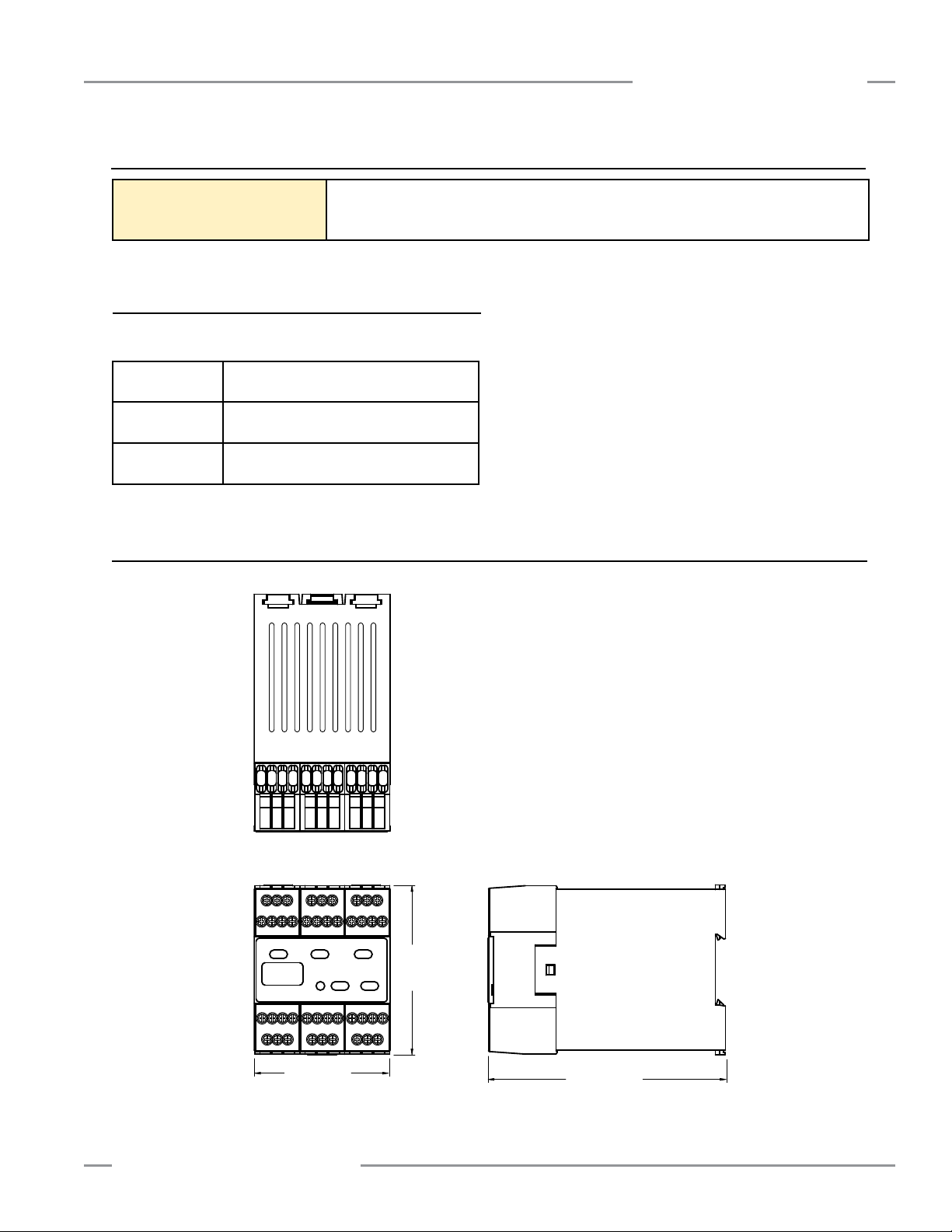
67.5 mm (2.65")
86.0 mm
(3.38")
118.0 mm (4.65")
Instruction Manual
2.1 Specifications, continued
Application Notes Mute Timing Sequences: see Appendix A
Typical Muting Applications: see Appendix B
Application Standards: see inside back cover
2.2 Accessories
Solid-State LED-Based Mute Lamp
System Installation
SSA-ML-W
SSA-ML-A
M18RGR5PNQ
2.3 Dimensions
+24V dc, White lens, stack-light style on
12" pole (see data sheet p/n 62097)
+24V dc, Amber lens, stack-light style on
12" pole (see data sheet p/n 62097)
+24V dc, Red, Green, Amber indication,
M18 EZ-LIGHT™ with 4-pin Euro-style QD
Banner Engineering Corp. • Minneapolis, U.S.A.
www.bannerengineering.com • Tel: 763.544.3164
P/N 116390 rev. C 11
Page 14
System Installation
3. System Installation
MMD-TA-11B / MMD-TA-12B Muting Module
Instruction Manual
3.1 Appropriate Application
The correct application of the MMD-TA-11B and -12B Muting
Modules is dependent on the type of machine and the
safeguards that are to be interfaced with the Module. The
Module is generally interfaced with safeguards that may be
used only on machinery that is capable of stopping motion
immediately upon receiving a stop signal and at any point in its
machine cycle. It is the user’s responsibility to verify whether the
safeguarding is appropriate for the application and is installed as
instructed by the appropriate installation manuals.
Safety Light Screens, Single/Multiple Beam Safety Systems,
or other Presence-Sensing Safeguarding Devices (PSSDs)
generally may not be used for the following:
• With single stroke (also called “full revolution”) clutched
machinery, as this type of machinery is incapable of stopping
immediately.
• On certain other types of machinery, including any machine
with inadequate or inconsistent stopping response time, or any
machine that ejects materials or component parts through the
defined area.
• In any environment likely to adversely affect the efficiency of
the safeguard(s) or the Muting Module. For example, corrosive
chemicals or fluids or unusually severe levels of smoke or dust,
if not controlled, may degrade the efficiency of a safety light
screen.
WARNING . . . Read this Section
Carefully Before Installing the System
The Banner MMD-TA-11B or -12B Muting
Module is an accessory device that is typically used in
conjunction with a machine safeguarding device. Its ability to
perform this function depends upon the appropriateness
of the application and upon the Muting Module’s proper
mechanical and electrical installation and interfacing to
the machine to be guarded.
If all mounting, installation, interfacing, and checkout
procedures are not followed properly, the Muting Module
cannot provide the protection for which it was designed.
The user has the responsibility to ensure that all local, state,
and national laws, rules, codes, or regulations relating to the
installation and use of this control system in any particular
application are satisfied. Extreme care should be taken to
ensure that all legal requirements have been met and that all
technical installation and maintenance instructions contained
in this manual are followed. Read Section 3 (and its
subsections) of this manual carefully before installing the
system. Failure to follow these instructions could result in
serious bodily injury or death.
The user has the sole responsibility to ensure that this Muting
Module is installed and interfaced to the guarded machine by
Qualified Persons (see Section 1.18), in accordance with this
manual and applicable safety regulations.
If there is any doubt about whether or not your machinery is
compatible with this Muting Module, contact Banner’s Application
Engineers at the factory.
WARNING . . . Stand-Alone Point-of-
Operation Guarding
The Muting Module is not a stand-alone pointof-operation guarding device, as defined by
OSHA regulations. It is necessary to install point-of-operation
guarding devices, such as safety light screens and/or hard
guards, to protect personnel from hazardous machinery.
Failure to properly install point-of-operation safeguarding
on hazardous machinery, as instructed by the appropriate
installation manuals, can result in a dangerous condition
which could lead to serious injury or death.
12 P/N 116390 rev. C
WARNING . . . User Is Responsible
for Safe Application of this Product
The muting application examples described in
Appendix B depict generalized guarding situations. Every
guarding application has a unique set of requirements.
Extreme care is urged to ensure that all legal
requirements are met and that all installation instructions
are followed. In addition, any questions regarding
safeguarding should be directed to the factory
applications department at the number or addresses listed
on the front cover.
Banner Engineering Corp. • Minneapolis, U.S.A.
www.bannerengineering.com • Tel: 763.544.3164
Page 15
MMD-TA-11B / MMD-TA-12B Muting Module
Instruction Manual
System Installation
3.1.1 Muting Application Design
Following are typical applications where muting is used. See
Appendix B for more detailed information.
• Entry/Exit Applications.
allow the entry or exit of a pallet or cart of work materials to
enter or exit a workstation without tripping the safety light
screen, and without allowing the entrance of personnel into the
hazardous area.
• Home or Station Applications.
placed to mute the safety light screen only when a hazard does
not exist or is in another area — so that personnel are not
exposed to any hazard.
• Robot Load/Unload Station Application.
application uses independent safety light screen circuits,
each with its own muting circuit and sensors to protect work
locations. When a robot is active in Station A, for example,
Station B safety light screen is muted.
• Turret Table Application.
similar to the Robot Load/Unload Station muting application,
except that any movement of the table ends the mute.
• Power Press Applications.
so that the mute is initiated only during the non-hazardous,
opening portion of the cycle (typically the machine upstroke).
The muting devices are placed to
The muting devices must be
The “Station” muting
A “Turret Table” application is
The muting devices are placed
WARNING . . . Muting Limitations
Muting is allowed only during the nonhazardous portion of the machine cycle (OSHA
1910.217(c)(3)(iii)(d), and ANSI B11.19.
3.1.2 Use of Corner Mirrors with Optical Safety Systems
Mirrors are typically used with safety light screens and single-/
multiple-beam safety systems to guard multiple sides of
a hazardous area. If the safety light screen is muted, the
safeguarding function is suspended on all sides. It must not
be possible for an individual to enter the guarded area without
being detected and a stop command issued to the machine
control. This supplemental safeguarding is normally provided
by an additional device(s) that remains active while the Primary
Safeguard is muted and could be interfaced with the SSI
input. Therefore, mirrors are typically not allowed for muting
applications.
3.1.3 Multiple Presence-Sensing Safety Devices (PSSDs)
Muting multiple PSSDs or a PSSD with multiple sensing fields
is not recommended unless it is not possible for an individual
to enter the guarded area without being detected and a stop
command issued to the machine control. As with the use of
corner mirrors (see above), if multiple sensing fields are muted
the possibility exists that personnel could move through a muted
area or access point to enter the safeguarded area without being
detected.
For example, in an entry/exit application where a pallet initiates
the mute cycle by entering a cell, if both the entry and the exit
PSSDs are muted, it may be possible for an individual to access
the guarded area through the “exit” of the cell. An appropriate
solution would be to mute the entry and the exit with separate
safeguarding devices.
Banner Engineering Corp. • Minneapolis, U.S.A.
www.bannerengineering.com • Tel: 763.544.3164
WARNING . . . Guarding Multiple
Areas
DO NOT safeguard multiple areas, with mirrors
or multiple sensing fields, if personnel can enter the
hazardous area while the System is muted, and not be
detected by supplemental safeguarding that will issue a
stop command to the machine (see Section 3.1.4, PassThrough Hazards).
P/N 116390 rev. C 13
Page 16

System Installation
MMD-TA-11B / MMD-TA-12B Muting Module
Instruction Manual
3.1.4 Pass-Through Hazards
A “pass-through hazard” is associated with applications where
personnel may pass through a safeguard (at which point the
hazard stops or is removed), and then may continue into the
hazardous area. Subsequently, their presence is no longer
detected, and the safeguard can not prevent the start or restart
of the machine. The related danger is the unexpected start or
restart of the machine while personnel are within the hazardous
area.
In the use of safety light screens, a pass-through hazard
typically results from large separation/safety distances calculated
from long stopping times, large defined area resolution, reach
over, reach through, or other installation considerations. A
pass-through hazard can be generated with as little as 75 mm
(3") between the defined area and the machine frame or hard
guarding.
Reducing or Eliminating Pass-Through Hazards
Measures must be taken to eliminate or reduce pass-through
hazards. One solution is to ensure that personnel are
continually sensed while within the hazardous area. This can be
accomplished by using supplemental safeguarding, including:
safety mats, area scanners, and horizontally mounted safety
light screens. While it is recommended to eliminate the passthrough hazard altogether, this may not be possible due to cell
or machine layout, machine capabilities, or other application
considerations.
An alternate method is to ensure that once the safeguarding
device is tripped it will latch, and require a deliberate manual
action to reset. This type of supplemental safeguarding relies
upon the location of the reset switch as well as safe work
practices and procedures to prevent an unexpected start or
restart of the guarded machine.
The reset switch or actuating control must be positioned outside
the guarded area, and provide the switch operator with a full
unobstructed view of the entire guarded area and any associated
hazards as the reset is performed. The reset switch or actuating
control must not be reachable from within the guarded area and
must be protected (through the use of rings or guards) against
unauthorized or inadvertent operation. A key-actuated reset
switch provides some operator control, as it can be removed
by the operator and taken into the guarded area. However,
this does not prevent unauthorized or inadvertent resets due to
spare keys in the possession of others, or additional personnel
entering the safeguarded area unnoticed.
The reset of a safeguard must not initiate hazardous motion.
Also, before each reset of the safeguard is performed, safe
work procedures require that a start-up procedure be followed
and that the individual performing the reset verify that the entire
hazardous area is clear of all personnel. If any areas can not be
observed from the reset switch location, additional supplemental
safeguarding must be used: at a minimum, visual and audible
warnings of machine start-up.
14 P/N 116390 rev. C
WARNING . . . Pass-Through Hazards,
Presence-Sensing Safeguarding
Devices, and Muting
If the presence-sensing safeguarding device
(PSSD) is guarding an application in which personnel
have access into the sensing area or field (for example,
a machine operator at the point of operation) while
the PSSD is muted, all pass-through hazards must be
eliminated. The individual must be sensed continually
while in the safeguarded area; this will prevent initiation
of a machine cycle if the mute ends while the individual is
within the hazardous area. See Appendix B for examples.
If the pass-through hazard cannot be eliminated, as in
entry/exit applications, the individual must be detected
entering the safeguarded area and the hazardous motion
must stop immediately.
3.2 Installing the Module
The Muting Module mounts to a standard 35 mm DIN-rail track.
The Module must be installed inside an enclosure rated NEMA 3
(IEC IP 54) or better. It can be mounted in any orientation. It
must be used with a properly installed and applied safeguard
(e.g., safety light screen, interlocked barrier guard). The user
must comply with all instructions contained within product
manuals and relevant regulations.
For reliable operation, the user must ensure that the operating
specifications are not exceeded. The enclosure must provide
adequate heat dissipation, so that the air closely surrounding the
Module does not exceed its maximum operating temperature.
Methods to reduce heat build-up include venting, forced air flow
(e.g., exhaust fans), adequate enclosure exterior surface area,
and spacing between Modules and other sources of heat. (See
Specifications, “Operating Conditions.”)
Mount the Module in a convenient location that is free from
heavy impulse force and high-amplitude vibration.
Electrostatic Discharge (ESD) can cause damage to electronic
equipment. To prevent this, follow proper ESD handling
practices such as:
• Wear an approved wrist strap or other approved grounding
products.
• Touch a grounded object before handling the Module.
See ANSI/ESD S20.20 for further information about managing
ESD.
Banner Engineering Corp. • Minneapolis, U.S.A.
www.bannerengineering.com • Tel: 763.544.3164
Page 17
MMD-TA-11B / MMD-TA-12B Muting Module
Instruction Manual
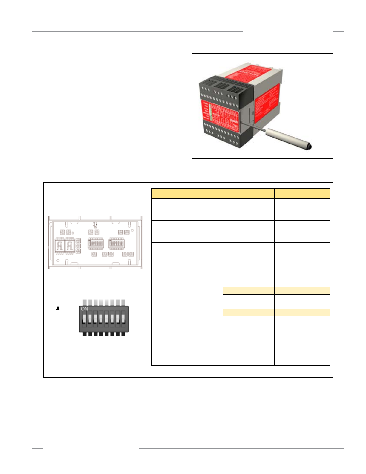
3.3 Muting Module Configuration
The Muting Module should be configured before initial checkout
and use. Two banks of DIP switches are located under the front
cover. To access the DIP switches, use a screwdriver to gently
pry the cover loose from the Module housing.
Because the Module has redundant microprocessors, two DIP
switch banks (Bank A and Bank B) must be set identically.
Failure to set Bank A and Bank B identically will result in a
lockout condition. Power must be OFF when changing DIP
switch settings; changing settings while power is ON will cause a
lockout condition. The parameters to be manually configured are
shown in Figure 3-2.
Switch ON Position OFF Position
Switch
Bank A
Switch
Bank B
Auto/Manual
1
MSSI Reset
(See Section 1.3)
System InstallationSystem Installation
Figure 3-3. Use a screwdriver to gently pry the cover loose
from the Module housing.
MSSI auto reset MSSI manual reset*
Auto/Manual
2
SSI Reset
(See Section 1.3)
One-Way or Two-Way
3
Mute Initiate Sequence
(See Section 1.17)
One-Channel or
4
Two-Channel EDM
(See Section 1.10)
Factory Default Settings
ON
OFF
1 2 3 4 5 6 7 8
NOTE: Switch numbers, e.g. “SW 1,” refer to
both switch banks A and B.
Backdoor Time-Out
5–6
(See Section 1.14)
Monitored/Non-Monitored
7
Mute Lamp
(See Section 1.12)
8 Mute on Power-Up Mute on power-up No mute on power up*
* Factory default setting
Figure 3-2. Muting Module manual configuration parameters
SSI auto reset SSI manual reset*
Two-way muting One-way muting*
One-channel EDM Two-channel or no EDM*
5 ON, 6 ON 5 ON, 6 OFF
No backdoor
time-out (infinite)
5 OFF, 6 ON 5 OFF, 6 OFF
60-second backdoor
time-out
Mute lamp not
monitored
30-minute backdoor
time-out
30-second backdoor
time-out*
Mute lamp monitored*
Banner Engineering Corp. • Minneapolis, U.S.A.
www.bannerengineering.com • Tel: 763.544.3164
P/N 116390 rev. C 15
Page 18
System Installation
A1 X1 X2
S11 S12 S21 S22
Z21 M1 Z11
X5 X6 X7 X8
Z12 M2 Z22
Z13 M3 Z23
Z14 M4 Z24 X13 X14 A2
X9 X10 X11
X12
Y1 Y2 Y3 Y4 X3 X4 Z3 Z4 Y5 Y6 Y7
Y8
A1 X1 X2
S11 S12 S21 S22
Z21 M1 Z11
X5 X6 X7 X8
Z12 M2 Z22
Z13 M3 Z23
Z14 M4 Z24 X13 X14 A2
X9 X10 X11
X12
Y1 Y2 Y3 Y4 X3 X4 31 32 13 14 23
24
MMD-TA-11B / MMD-TA-12B Muting Module
Instruction Manual
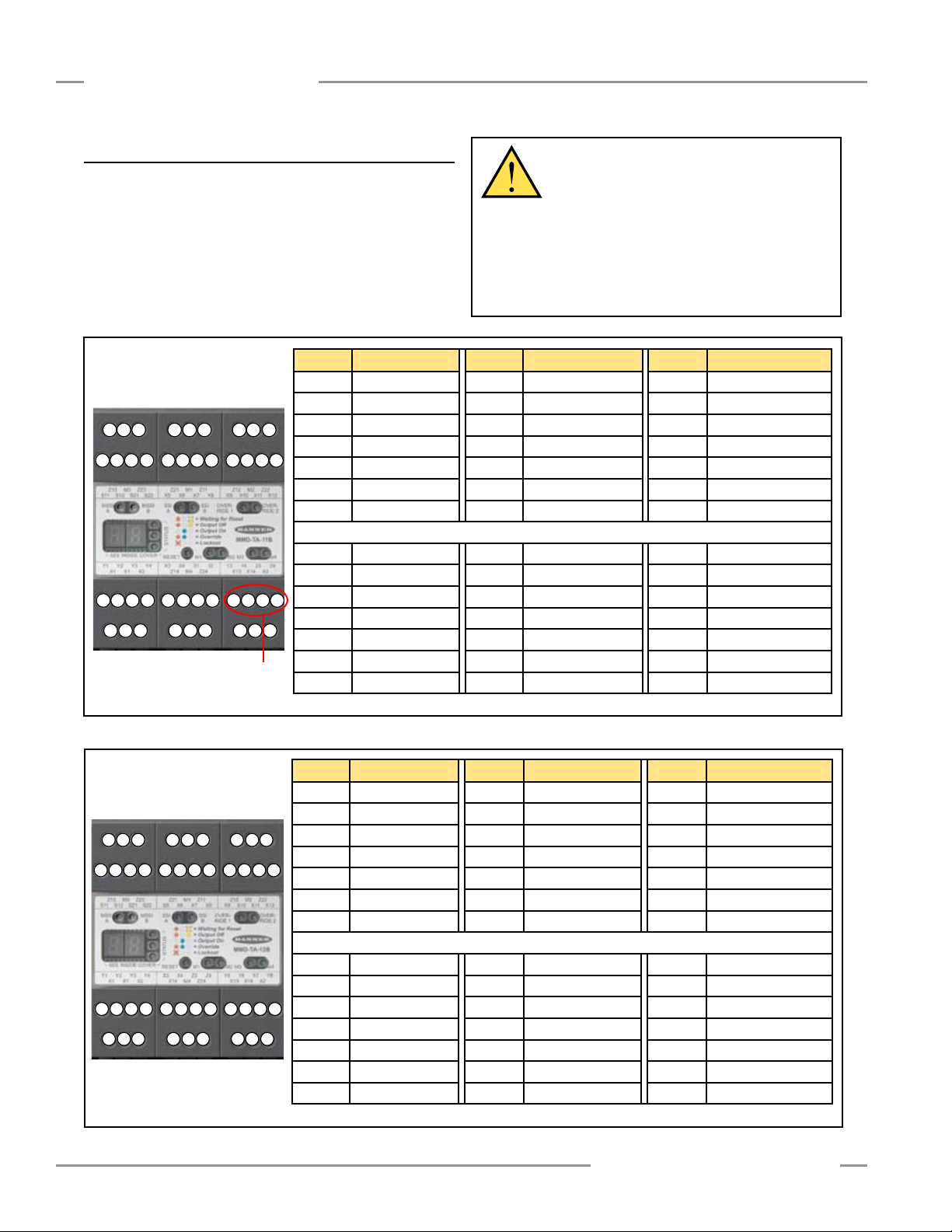
3.4 Connection Terminals and Functions
All electrical connections are made through removable terminals
(see Figures 3-4a and 3-4b).
To disable the SSI, terminal X5 (SSIb) must be jumpered to
terminal X6 (SSIa), and terminal X7 (SSId) must be jumpered to
terminal X8 (SSIc) (factory default). Do not short Channel A to
Channel B.
All terminals are low-voltage,
except for those indicated
otherwise
Potential
High-Voltage
Terminals
Terminal Function Terminal Function Terminal Function
Z13 M3, 0V Z21 M1, 24V Z12 M2, 0V
M3 Muting 3 In (PNP) M1 Muting 1 In (PNP) M2 Muting 2 In (NPN)
Z23 M3, 24V Z11 M1, 0V Z22 M2, 24V
S11 MSSI b (ch A) X5 SSI b (ch A) X9
S12 MSSI a (ch A) X6 SSI a (ch A) X10
S21 MSSI d (ch B) X7 SSI d (ch B) X11
S22 MSSI c (ch B) X8 SSI c (ch B) X12
Y1 EDM 1 a Out (24V) X3 Mute Lamp Out (24V) 13 OSSD 1 a (Relay)
Y2 EDM 1 b In X4 Mute Lamp In 14 OSSD 1 b (Relay)
Y3 EDM 2 b In 31 AUX a (Relay) 23 OSSD 2 a (Relay)
Y4 EDM 2 a Out (24V) 32 AUX b (Relay) 24 OSSD 2 b (Relay)
A1 +24V dc Z14 M4, 0V X13 Mute Enable Out (24V)
X1 Reset In M4 Muting 4 In (NPN) X14 Mute Enable In
X2 Reset Out (24V) Z24 M4, 24V A2 0V dc
WARNING . . . Proper Electrical
Hookup
Electrical hookup must be made by Qualified
Personnel and must comply with NEC (National Electrical
Code) and local standards.
Make no connections to the System other than those
described in Section 3 of this manual. Doing so could result
in serious injury or death.
Override a (ch A)*
Override b (ch A)*
Override c
(ch B)*
Override d
(ch B)*
*contacts only
Figure 3-4a. MMD-TA-11B terminal connection locations
All terminals are low-voltage
Figure 3-4b. MMD-TA-12B terminal connection locations
16 P/N 116390 rev. C
Terminal Function Terminal Function Terminal Function
Z13 M3, 0V Z21 M1, 24V Z12 M2, 0V
M3 Muting 3 In (PNP) M1 Muting 1 In (PNP) M2 Muting 2 In (NPN)
Z23 M3, 24V Z11 M1, 0V Z22 M2, 24V
S11 MSSI b (ch A) X5 SSI b (ch A) X9
S12 MSSI a (ch A) X6 SSI a (ch A) X10
S21 MSSI d (ch B) X7 SSI d (ch B) X11
S22 MSSI c (ch B) X8 SSI c (ch B) X12
Y1 EDM 1 a Out (24V) X3 Mute Lamp Out (24V) Y5 OSSD 1 a Out
Y2 EDM 1 b In X4 Mute Lamp In Y6 OSSD 1 b 0V
Y3 EDM 2 b In Z3 AUX b 0V Y7 OSSD 2 b 0V
Y4 EDM 2 a Out (24V) Z4 AUX a Out Y8 OSSD 2 a Out
A1 +24V dc Z14 M4, 0V X13 Mute Enable Out (24V)
X1 Reset In M4 Muting 4 In (NPN) X14 Mute Enable In
X2 Reset Out (24V) Z24 M4, 24V A2 0V dc
Banner Engineering Corp. • Minneapolis, U.S.A.
www.bannerengineering.com • Tel: 763.544.3164
Override a
Override b
Override c
Override d
*contacts only
(ch A)*
(ch A)*
(ch B)*
(ch B)*
Page 19

MMD-TA-11B / MMD-TA-12B Muting Module
X1
X2
Instruction Manual
System Installation
To remove a terminal block, insert
a small screwdriver into the slot
shown, and pry to loosen.
When reinserting a terminal block,
take care to slide the dovetail on
the terminal block into the slot on
the frame.
Figure 3-5. Removal of terminal blocks
3.5 Installing Input Devices
3.5.1 Manual Reset Switch
The manual reset switch connects to Module terminals X1 and
X2 (see Figure 3-6). See Section 3.3 for Auto/Manual Reset
configuration.
Any reset switches must be located so that a reset is possible
only from outside, and in full view of, the hazardous area. The
switch must also be out of reach from within the safeguarded
space. If any hazardous areas are out of view from the switch
location, additional means of safeguarding must be provided.
The switch must be protected from accidental or unintended
actuation (e.g., through the use of rings or guards).
Using a key switch provides some level of personal control,
because the key may be removed. This will hinder a reset while
the key is under the control of an individual, but must not be
relied upon solely to guard against accidental or unauthorized
reset. Spare keys in the possession of others, or additional
personnel entering the safeguarded area unnoticed may create a
hazardous situation.
Reset Routine
The Muting Module requires a manual reset to clear a latch
condition and resume operation following a stop command. To
perform a manual reset, close the normally open reset switch
and hold it there for at least 1/4 second, but not longer than 2
seconds, and then re-open the switch. Internal lockout conditions
also require a manual reset to return the system to RUN mode
after the failure has been corrected and the input correctly
cycled.
Figure 3-6. Manual Reset switch connections
WARNING . . . Location of the
Manual Reset Switch
The reset switch must be located outside of,
and not be accessible from within, the dangerous area,
and it must be positioned so that the dangerous area
may be observed by the switch operator during the reset
operation.
Banner Engineering Corp. • Minneapolis, U.S.A.
www.bannerengineering.com • Tel: 763.544.3164
P/N 116390 rev. C 17
Page 20

System Installation
MMD-TA-11B / MMD-TA-12B Muting Module
Instruction Manual
3.5.2 Muting Devices
The user is required by OSHA and ANSI to arrange, install,
and operate the safety system so as to protect personnel and
minimize the possibility of defeating the safeguard.
Mute devices must meet a 3-second simultaneity requirement to
activate muting; that is, devices in a pair must be activated within
3 seconds of one another.
General Muting Device Requirements
The muting devices (typically sensors or switches) must, at a
minimum, comply with the following requirements:
1. There must be a minimum of two independent hard-wired
muting devices.
2. The muting devices must either both have normally open
contacts; or one device with a PNP output and one device
with a NPN output, both of which must fulfill the input
requirements listed in the Specifications (Section 2). These
contacts must close when the switch is actuated, and must
open (or not conduct) when the switch is not actuated or in a
power OFF condition.
3. The activation of the inputs to the muting function must be
from separate sources. These sources must be mounted
separately in order to prevent an unsafe muting condition
resulting from misadjustment, misalignment, or a single
common mode failure. (For example, physical damage to
the mounting surface could cause both muting devices to
be knocked out of alignment, resulting in false muting input
signals.) Only one of these sources may pass through, or be
affected by, a programmable logic controller or similar device.
Examples of Muting Sensors and Switches
Photoelectric Sensors (Opposed Mode): Opposed-mode
sensors, which initiate the muted condition when the beam path
is blocked, should be configured for dark operate (DO) and have
open (non-conducting) output contacts in a power OFF condition.
Both the emitter and receiver from each pair should be
powered from the same source, to eliminate common mode
failures.
Photoelectric Sensors (Polarized Retroreflective Mode): The
user must ensure that false “proxing” (activation due to shiny
or reflective surfaces) is not possible. Banner “LP” sensors with
linear polarization can greatly reduce or eliminate this effect.
Use a sensor configured for Light Operate (LO or N.O.) if
initiating a mute when the retroreflective target or tape is
detected (e.g., home position). Use a sensor configured for Dark
Operate (DO or N.C.) when a blocked beam path initiates the
muted condition (e.g., entry/exit). Both situations must have open
(non-conducting) output contacts in a power OFF condition.
Positive-Opening Safety Switches: Two (or four) independent
switches, each with a minimum of one closed safety contact to
initiate the mute cycle, are typically used. An application using
a single switch with a single actuator and two closed contacts
could result in an unsafe situation.
Inductive Proximity Sensors: Typically, inductive proximity
sensors are used to initiate a muted cycle when a metal surface
is detected. Due to excessive leakage current causing false ON
conditions, two-wire sensors are not to be used. Only three- or
four-wire sensors that have discrete PNP, NPN, or hard-contact
outputs that are separate from the input power can be used.
4. The muting devices must be installed so that they can not be
easily defeated or bypassed.
5. The muting devices must be mounted so that their physical
position and alignment can not be easily changed.
6. It must not be possible for environmental conditions to initiate
a mute condition (e.g., extreme airborne contamination).
7. The muting devices must not be set to use any delay or other
timing functions (unless such functions are accomplished so
that no single component failure prevents the removal of the
hazard, subsequent machine cycles are prevented until the
failure is corrected, and no hazard is created by extending the
muted period).
18 P/N 116390 rev. C
WARNING . . . Avoid Hazardous
Installations
Two or four independent position switches (at
M1–M2 or M3–M4) must be properly adjusted or positioned
so that they close only after the hazard no longer exists,
and open again when the cycle is complete or the hazard
is again present. If improperly adjusted or positioned,
injury or death could result.
The user has the responsibility to satisfy all local, state, and
national laws, rules codes, and regulations relating to the use
of safety equipment in any particular application. It is extremely
important to be sure that all appropriate agency requirements
have been met and that all installation and maintenance
instructons contained in the appropriate manuals are followed.
Banner Engineering Corp. • Minneapolis, U.S.A.
www.bannerengineering.com • Tel: 763.544.3164
Page 21

MMD-TA-11B / MMD-TA-12B Muting Module
+
-
+
-
A1
Z21
M1
M1PNP
-
+
NPN
-
+
+24V dc
Z11
Z23
M3
M3PNP
-
+
Z13
Z22
M2
M2 or
or
Z12
MMD-TA-..B
NPN
-
+
Z24
M4
M4
Z14
+
-
+
-
A1
Z21
M1 M1PNP
-
+
PNP
-
+
NPN
-
+
NPN
-
+
+24V dc
Z11
Z23
M3 M3
Z13
Z22
M2 M2
Z12
Z24
M4 M4
MMD-TA-..B
Z14
Carrier
Basket
M1
M3
M2 M4
E
R
Light
Screen
+
-
A1
Z21
M1
M1PNP
PNP
+
-
NPN
-
+
NPN
-
+
+24V dc
Polarized
Retro
Z11
Z23
M3
M3PNP
-
+
Z13
Z22
M2
M2 or
or
Z12
MMD-TA-..B
NPN
-
+
Z24
M4
M4
Z14
Instruction Manual
Muting Device Hookup
The Module provides supply voltage, if required, and input
connections for the muting devices. One or two pairs of muting
devices (typically sensors or switches) must be used; these pairs
are designated M1-M2 and M3-M4. The M1 and M3 inputs are
PNP (sourcing). The M2 and M4 inputs are NPN (sinking). Also
available are terminals to supply power (+24V dc) to the muting
devices.
The current draw of all devices must not exceed 500 mA.
System Installation
Figure 3-8. Relay (hard contact) output sensors
Figure 3-7. Four Limit Switches as M1, M2, M3, and M4
Banner Engineering Corp. • Minneapolis, U.S.A.
www.bannerengineering.com • Tel: 763.544.3164
Figure 3-9. Two (or four) sensors using semiconductor outputs
P/N 116390 rev. C 19
Page 22

System Installation
Override A
Override B
X9
X10
X11
X12
Mute
Lamp
X3
X4
+
+
-
+V
0V
Z4
Z3
Load
V+
0V
K1 K2
31
32
Load
3.5.3 Mute Lamp Output (ML)
The Mute Lamp output provides for the visible indication that the
safety device’s safeguarding function is muted. This indication
must be readily observable. Failure of this indication should be
detectable and prevent the safeguard from being muted, or the
operation of the indicator should be verified at suitable intervals
(see Section 1.13). The Mute Lamp output also flashes to
indicate an Override condition (see Section 1.16).
The Module can be configured for a monitored or non-monitored
mute lamp. It is the user’s responsibility to make sure that each
application meets local regulations. If the installation is governed
by UL regulations, the mute lamp must be monitored (SW7 =
OFF, banks A and B). This output may also be used as an input
to control logic (e.g., a PLC) if “non-monitored” is selected (SW7
= ON, banks A and B). The current draw of the mute lamp must
not exceed 360 mA. See Figure 3-10.
MMD-TA-11B / MMD-TA-12B Muting Module
Instruction Manual
Figure 3-10. Mute Lamp output hookup
3.5.4 Auxiliary Output (AUX)
Model MMD-TA-11B: The non-safety-related output on this
model is a 24V ac/dc, 250 mA normally-closed relay contact.
See Output Specifications on page 9. See Figure 3-11a.
Model MMD-TA-12B: A non-safety-related PNP output is
available at terminals Z3–Z4. This monitoring output is for lightduty, non-safety-related control functions, such as an input to
a programmable logic controller (PLC). This output follows the
OSSD outputs. Maximum current draw of the AUX output is
250 mA. See Figure 3-11b.
3.5.5 Override Switch Hookup
The Module provides connection terminals for the Override
switches (see Figure 3-12). See Section 1.16 and the warning
below before connecting switches.
WARNING . . . Limit Use of Override
Function
The Override function is not for machine setup
or production; it is to be used only to clear the primary
safeguard if material becomes “stuck,” preventing
its reset. When Override is used, it is the user’s
responsibility to install and use it according to current
standards. In addition, the requirements listed in standards
ANSI NFPA 79 and IEC/EN 60204-1 must be satisfied.
Figure 3-11a. AUX output hookup – MMD-TA-11B
Figure 3-11b. AUX output hookup – MMD-TA-12B
Figure 3-12. Override switch hookup
20 P/N 116390 rev. C
Banner Engineering Corp. • Minneapolis, U.S.A.
www.bannerengineering.com • Tel: 763.544.3164
Page 23
MMD-TA-11B / MMD-TA-12B Muting Module
Instruction Manual
System Installation
3.5.6 SSI and MSSI Interfacing
The Safety Stop Interface (SSI) provides easy integration of
safeguards. This interface consists of two input channels (A
and B), which are compatible with Banner Engineering safety
devices that have solid-state OSSD outputs or other devices with
sourcing +24V dc outputs. SSI is also compatible with devices
that have normally open hard contacts or relay outputs (voltagefree).
The Muteable Safety Stop Interface (MSSI) input is a specialized
SSI that can be muted during the non-hazardous portion of the
machine cycle.
The input channels (A and B) must meet a simultaneity
requirement of 3.0 seconds upon closing and opening. A
mismatch of more than 3.0 seconds will result in a lockout. A
lockout that is due to a failure to meet simultaneity requirements
can only be cleared by:
1. Cycling the MSSI (or the SSI, depending on which failed) with
simultaneity being met, and then
2. If the Module is configured for Manual Reset, performing a
reset routine (see Section 1.3).
The MSSI and the SSI can be interfaced with devices with solidstate OSSD outputs, safety interlocking switches, E-stop buttons,
rope/cable pull devices, and other machine control devices that
switch +24Vdc. To be interfaced with a safety mat, a safety mat
controller must be connected between the mat and the interface
(see Figure 3-22).
If the SSI is not to be used, the input channels must be
NOTE:
jumpered. See Section 3.4.
WARNING . . . Emergency Stop
Functions
Do not connect any Emergency Stop devices
to the MSSI Input; do not mute or bypass any Emergency
Stop device. ANSI NFPA79 and IEC/EN 60204-1 require that the
Emergency Stop function remain active at all times. Muting or
bypassing the safety outputs will render the Emergency Stop
function ineffective.
3.5.6.1 Safety Circuit Integrity and ISO 13849-1 (EN954-1)
Safety Circuit Principles
Safety circuits involve the safety-related functions of a machine
that minimize the level of risk of harm. These safety-related
functions can prevent initiation, or they can stop or remove a
hazard. The failure of a safety-related function or its associated
safety circuit usually results in an increased risk of harm.
The integrity of a safety circuit depends on several factors,
including fault tolerance, risk reduction, reliable and well-tried
components, well-tried safety principles, and other design
considerations.
Depending on the level of risk associated with the machine or
its operation, an appropriate level of safety circuit performance
(i.e., integrity) must be incorporated into the design. Standards
that detail safety performance levels include ANSI/RIA
R15.06 Industrial Robots, ANSI B11 Machine Tools, OSHA
29CFR1910.217 Mechanical Power Presses, and ISO 13849-1
(EN954-1) Safety-Related Parts of a Control System.
Safety Circuit Integrity Levels
Safety circuits in International and European standards have
been segmented into categories, depending on their ability
to maintain their integrity in the event of a failure. The most
recognized standard that details safety circuit integrity levels
is ISO 13849-1 (EN954-1), which establishes five levels:
Categories B, 1, 2, 3, and the most stringent, Category 4.
In the United States, the typical level of safety circuit integrity
has been called ”control reliability.” Control reliability typically
incorporates redundant control and self-checking circuitry and
has been loosely equated to ISO 13849-1 Categories 3 and 4
(see CSA Z432 and ANSI B11.TR4).
If the requirements described by ISO 13849-1 (EN954-1) are
to be implemented, a risk assessment must first be performed
to determine the appropriate category, in order to ensure that
the expected risk reduction is achieved. This risk assessment
must also take into account national regulations, such as U.S.
control reliability or European “C” level standards, to ensure that
the minimum level of performance that has been mandated is
complied with.
Fault Exclusion
An important concept within the category requirements of ISO
13849-1 (EN954-1) is the “probability of the occurrence of the
failure,” which can be decreased using a technique termed “fault
exclusion.” The rationale assumes that the possibility of certain
well-defined failure(s) can be reduced to a point where the
resulting fault(s) can be, for the most part, disregarded—that is,
“excluded.”
Fault exclusion is a tool a designer can use during the
development of the safety-related part of the control system
and the risk assessment process. Fault exclusion allows the
designer to design out the possibility of various failures and
justify it through the risk assessment process to meet the intent
requirements of Category 2, 3 or 4. See ISO 13849-1/-2 for
further information.
WARNING . . . SSI and MSSI Safety
Categories
The level of safety circuit integrity can be
greatly impacted by the design and installation of the safety
devices and the means of interfacing of those devices. A
risk assessment must be performed to determine the
appropriate safety circuit integrity level or safety category
as described by ISO 13849-1 (EN 954-1) to ensure that the
expected risk reduction is achieved and that all relevant
regulations are complied with.
Banner Engineering Corp. • Minneapolis, U.S.A.
www.bannerengineering.com • Tel: 763.544.3164
P/N 116390 rev. C 21
Page 24

System Installation
+24V dc 0V
(a)
MSSI or SSI
(b)
(c)
(d)
MMD-TA-..B
A1
S12
S11
A2
S22
S21
X6
X5
X8
X7
(a)
MSSI or SSI
(b)
(c)
(d)
A1
X6
X5
X7
X8
S12
S11
S21
S22
+24V dc 0V
MMD-TA-..B
A2
+24V dc
EZ-SCREEN
Type 2
0V
0V*+V
(a)
MSSI or SSI
(b)
(c)
(d)
MMD-TA-..B
A1
S12
S11
A2
+
+
S22
S21
X6
X5
X8
X7
+24V dc
Safeguard with
Output Fault
Monitoring
0V
(a)
MSSI or SSI
(b)
(c)
(d)
MMD-TA-..B
A1
S12
S11
A2
+
+
S22
S21
X6
X5
X8
X7
MMD-TA-11B / MMD-TA-12B Muting Module
Instruction Manual
3.5.6.2 Generic SSI and MSSI Hookups
To fully understand category requirements, refer to standard
ISO 13849-1 (EN954-1). The following is general in nature
and is intended to provide only basic guidance. Each guarding
application has its unique set of requirements; it is the user’s
responsibility to ensure that all local, state, and national laws,
rules, codes, and regulations are satisfied.
In addition to the use of well-tried, tested, and robust
components, and generally accepted principles (including fault
exclusion), the safety function depends on the use of safetyrated devices. These devices are specially designed to reduce
the probability of failing to an unsafe condition, and typically are
third-party certified to a recognized safety standard.
Category 2
To meet the requirements of a category 2 application, any device
connected to the SSI and MSSI inputs must meet certain criteria.
For example, a “type 2” light screen (curtain) that meets IEC
61496-1/-2 is a device that meets category 2 requirements.
A category 2 safety function must be tested/checked at suitable
intervals, the frequency determined by the application’s risk
assessment. It should be noted that a single fault may cause the
loss of the safety function.
Category 3
To meet the requirements of a category 3 application, any device
connected to the SSI and MSSI inputs must meet certain criteria.
For example, a “type 3” laser area scanner that meets IEC
61496-1/-3 is a device that meets category 3 requirements.
In a category 3 safety application, a single fault must not cause
the loss of the safety function. This is usually accomplished
by using redundant safety inputs or outputs from the safetyrated device. Faults should be detected whenever reasonably
practicable, although a short circuit between input channels or
safety outputs may not be detected. It should be noted that an
accumulation of faults may cause the loss of the safety function.
The principle of fault exclusion must be incorporated into the
design and installation to either eliminate, or reduce to an
acceptable (minimal) level of risk, the possibility of undetected
faults or catastrophic failures that could result in the loss of the
safety function.
The principle of fault exclusion must be incorporated into the
design and installation to either eliminate, or reduce to an
acceptable (minimal) level of risk, the possibility of undetected
faults or failures that can result in the loss of the safety function.
Figure 3-13a. MSSI and SSI Category 2 interfacing: positive-
opening switch
safeguarding device (e.g., EZ-SCREEN “Type 2”
or AOPD type 2 per IEC 61496-1/-2)
Figure 3-13b. MSSI and SSI Category 2 interfacing: Category 2
22 P/N 116390 rev. C
Figure 3-14a. MSSI and SSI Category 3 interfacing: two
positive-opening switches per single guard
Figure 3-14b. MSSI and SSI Category 3 interfacing: category 3
safeguarding device with output fault monitoring
(e.g., type 3 area scanner AOPDDR per
IEC 61496-1/-3)
Banner Engineering Corp. • Minneapolis, U.S.A.
www.bannerengineering.com • Tel: 763.544.3164
Page 25
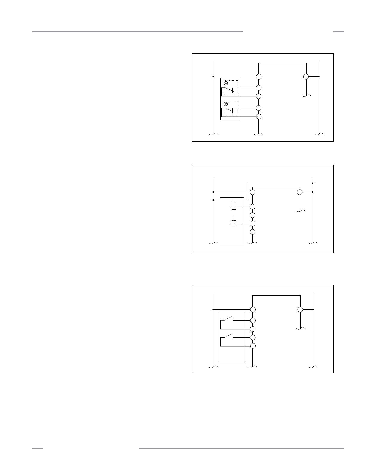
MMD-TA-11B / MMD-TA-12B Muting Module
(a)
MSSI or SSI
(b)
(c)
(d)
A1
X6
X5
X7
X8
S12
S11
S21
S22
+24V dc 0V
MMD-TA-..B
A2
+24V dc
EZ-SCREEN
Type 4
0V
(a)
MSSI or SSI
(b)
(c)
(d)
MMD-TA-..B
A1
S12
S11
A2
+
+
S22
S21
X6
X5
X8
X7
(a)
MSSI or SSI
(b)
(c)
(d)
A1
X6
X5
X7
X8
S12
S11
S21
AOPD
Type 4
S22
+24V dc 0V
MMD-TA-..B
A2
Instruction Manual
Category 4
To ensure a category 4 application, any device connected to the
SSI and MSSI inputs must meet certain criteria. For example, a
“type 4” safety light screen (curtain) that meets IEC 61496-1/-2 is
a device that meets category 4 requirements.
In a category 4 application, a single fault must not cause the loss
of the safety function. The fault must be detected at or before
the next demand of the safety function, and an accumulation of
faults also must not cause the loss of the safety function.
This is usually accomplished by the use of redundant safety
inputs or outputs from the safety-rated device that are monitored
to detect certain faults. These faults include:
• Increased response time
• Prevention of one or more safety outputs (OSSDs) going to the
OFF-state
• A short circuit between channels
System Installation
Figure 3-15a. MSSI and SSI Category 4 interfacing: two
positive-opening switches per single guard
NOTE: Solid-state safety outputs, such as those from
EZ-SCREEN Type 4 safety light screens, typically
achieve this level of fault tolerance by self-monitoring a
pulsing of the outputs. Safety devices with hard-contact
or relay outputs must be connected in a “4-wire” method
as shown in Figure 3-15c.
The principle of fault exclusion must be incorporated into the
design and installation to either eliminate, or reduce to an
acceptable (minimal) level of risk, the possibility of catastrophic
failures/faults that could result in the loss of the safety function.
Figure 3-15b. MSSI and SSI Category 4 interfacing: category 4
safeguarding device with output fault monitoring
(e.g., EZ-SCREEN or AOPD Type 4 per IEC 614961/-2)
Banner Engineering Corp. • Minneapolis, U.S.A.
www.bannerengineering.com • Tel: 763.544.3164
Figure 3-15c. MSSI and SSI Category 4 interfacing: category 4
safeguarding device with relay outputs (e.g.,
MINI-SCREEN or AOPD Type 4 per IEC 61496-1/-2)
P/N 116390 rev. C 23
Page 26
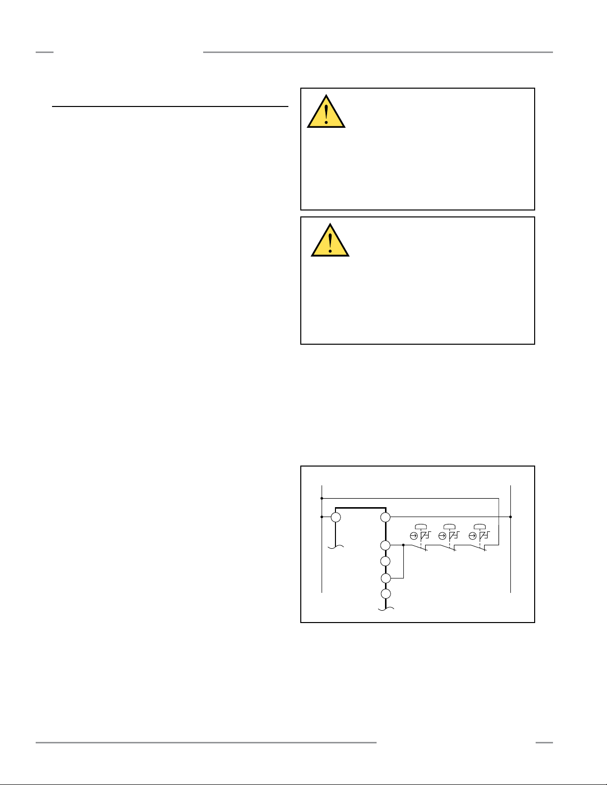
System Installation
0V dc+24V dc
X6 (a)
X5 (b)
X8 (c)
X7 (d)
A2A1
SSI
MMD-TA-..B
MMD-TA-11B / MMD-TA-12B Muting Module
Instruction Manual
3.5.6.3 SSI Emergency Stop Switch Device Hookup
Emergency Stop Push Button Switches
As shown in Figures 3-16, 3-17 and 3-18, the E-stop switch must
provide one or two contacts for safety which are closed when
the switch is armed. Once activated, the E-stop switch must
open all its safety-rated contacts, and must require a deliberate
action (such as twisting, pulling, or unlocking) to return to the
closed-contact, armed position. The switch should be a “positiveopening” (or direct-opening) type, as described by IEC 60947-5-1.
A mechanical force applied to such a button (or switch) is
transmitted directly to the contacts, forcing them open. This
ensures that the switch contacts will open whenever the switch
is activated.
Standards ANSI NFPA 79, IEC/EN 60204-1, and ISO 13850
specify additional emergency stop switch device requirements,
including the following:
• Emergency Stop push buttons shall be located at each operator
control station and at other operating stations where emergency
shutdown is required.
• Stop and Emergency Stop push buttons shall be continuously
operable and readily accessible from all control and operating
stations where located. Do not connect E-stop buttons to the
MSSI.
• Actuators of Emergency Stop devices shall be colored Red.
The background immediately around the device actuator shall
be colored Yellow. The actuator of a push-button-operated
device shall be of the palm or mushroom-head type.
• The Emergency Stop actuator shall be a self-latching type.
WARNING . . . Emergency Stop
Functions
Do not connect any device to the MSSI Input
that is used for an emergency stop function. Never mute
or bypass any emergency stop device (e.g., a button or
rope pull). ANSI NFPA 79 and IEC/EN 60204-1 require that
the emergency stop function remain active at all times.
Muting or bypassing the safety outputs will render the
Emergency Stop function ineffective.
WARNING . . . Reset Routine
Required
U.S. and international standards require that a
reset routine be performed after returning the E-stop switch to
its closed-contact position (when arming the E-stop switch).
When automatic reset is used, an alternate means must be
established to require a reset routine, after the E-stop switch
is armed. Allowing the machine to restart as soon as the
E-stop switch is armed creates an unsafe condition which
could result in serious injury or death.
Category 2
A single-channel emergency stop application typically provides
a category 2 level of circuit performance, because a short circuit
could cause the loss of the safety function. The principle of fault
exclusion must be incorporated into the design and installation
to either eliminate, or reduce to an acceptable (minimal) level of
risk, the possibility of undetected faults or failures that can result
in the loss of the safety function.
NOTE: Some applications may have additional requirements.
The user must comply with all relevant regulations.
Safety Circuit Integrity Levels and Emergency Stop functions
As part of the required risk assessment for the machine, ANSI
NFPA 79 and IEC/EN 60204-1 state that the safety performance
(integrity) must reduce the risk from identified hazards as
determined by the risk assessment. See Sections 3.5.6.1 and
3.5.6.2 for guidance if the requirements as described by ISO
13849-1 (EN954-1) are to be implemented.
In addition to the requirements stated above, the design and
the installation of the emergency stop device (e.g., switch,
button, or rope-pull) must be such that the possibility of a
catastrophic failure of the device resulting in the loss of
the safety function must be excluded (designed out). Per ISO
13849-2, electromechanical devices that have contacts designed
in accordance to IEC 60947-5-1 Annex K and that are installed
per manufacturer’s instructions are expected to open when the
emergency stop device is actuated.
24 P/N 116390 rev. C
Figure 3-16. SSI Category 2 interfacing: positive-opening
E-stop switch(es)
Banner Engineering Corp. • Minneapolis, U.S.A.
www.bannerengineering.com • Tel: 763.544.3164
Page 27
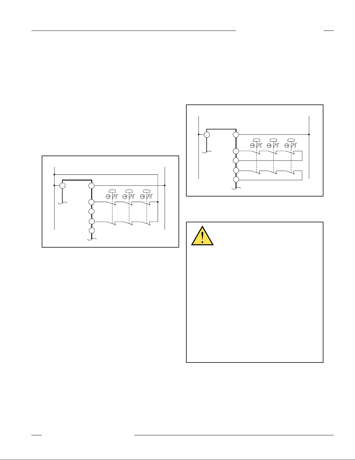
MMD-TA-11B / MMD-TA-12B Muting Module
0V dc+24V dc
X6 (a)
X5 (b)
X8 (c)
X7 (d)
A2A1
SSI
MMD-TA-..B
0V dc+24V dc
X6 (a)
X5 (b)
X8 (c)
X7 (d)
A2A1
SSI
MMD-TA-..B
Instruction Manual
System Installation
Category 3
A dual-channel hookup switching +24V dc is typically a category
3 application, because a single failure does not result in a loss
of safety. Loss of the switching action in one channel is detected
by the actuation of the E-stop button, the opening of the second
channel, and the monitoring function of the SSI inputs. However,
a short circuit between input channels or safety outputs may not
be detected. It should be noted that an accumulation of faults
may cause the loss of the safety function.
The principle of fault exclusion must be incorporated into the
design and installation to either eliminate, or reduce to an
acceptable (minimal) level of risk, the possibility of undetected
faults or catastrophic failures that could result in the loss of the
safety function.
Category 4
The self-monitoring SSI inputs can be interfaced to achieve a
category 4 application. The principle of fault exclusion must be
incorporated into the design and installation to either eliminate,
or reduce to an acceptable (minimal) level of risk, the possibility
of catastrophic failures or faults that could result in the loss of
the safety function.
Figure 3-18. SSI Category 4 interfacing: positive-opening
E-stop switch(es)
Figure 3-17. SSI Category 3 interfacing: positive-opening
E-stop switch(es)
WARNING . . . Multiple E-Stop
Switches
Whenever two or more Emergency Stop
switches are connected to the same Module:
• Contacts of the corresponding pole of each switch must
be connected together in series. Never connect the
contacts of multiple Emergency Stop switches in parallel
to one Module. Such a parallel connection connection
defeats the switch contact monitoring ability of the Module
and creates an unsafe condition which could result in serious
injury or death.
• Each switch must be individually actuated (engaged),
then re-armed and the Module reset. This allows the
controller to check each switch and its wiring to detect faults.
Failure to test each switch individually in this manner
could result in undetected faults and create an unsafe
condition which could result in serious injury or death.
This check must be performed during periodic checkouts
(see Section 6).
Banner Engineering Corp. • Minneapolis, U.S.A.
www.bannerengineering.com • Tel: 763.544.3164
P/N 116390 rev. C 25
Page 28

System Installation
MMD-TA-11B / MMD-TA-12B Muting Module
Instruction Manual
3.5.6.4 SSI/MSSI Interlocked Guard or Gate Hookup
The SSI (or MSSI) may be used to monitor electrically
interlocked safety guards or gates.
Safety Circuit Integrity Levels
Requirements vary widely for the level of control reliability or
safety category per ISO 13849-1 (EN954-1) in the application
of interlocked guards. While Banner Engineering always
recommends the highest level of safety in any application, it
is the responsibility of the user to safely install, operate and
maintain each safety system and comply with all relevant laws
and regulations.
The safety performance (integrity) must reduce the risk
from identified hazards as determined by the machine’s risk
assessment. See Sections 3.5.6.1 and 3.5.6.2 for guidance if the
requirements as described by ISO 13849-1 (EN954-1) are to be
implemented.
In addition to the requirements stated in this section, the design
and installation of the interlocking device should comply with
ANSI B11.19 or ISO 14119.
Safety Interlocking Switch Requirements
The following general requirements and considerations apply to
the installation of interlocked guards and gates for the purpose
of safeguarding. In addition, refer to the relevant regulations to
be sure to comply with all necessary requirements.
Hazards guarded by the interlocked guard must be prevented
from operating until the guard is closed; a stop command must
be issued to the guarded machine if the guard opens while the
hazard is present. Closing the guard must not, by itself, initiate
hazardous motion; a separate procedure must be required to
initiate the motion. The safety switches must not be used as a
mechanical or end-of-travel stop.
The guard must be located an adequate distance from the
danger zone (so that the hazard has time to stop before the
guard is opened sufficiently to provide access to the hazard),
and it must open either laterally or away from the hazard, not
into the safeguarded area. The guard also should not be able to
close by itself and activate the interlocking circuitry. In addition,
the installation must prevent personnel from reaching over,
under, around or through the guard to the hazard. Any openings
in the guard must not allow access to the hazard (see OSHA
29CFR1910.217 Table O-10, ANSI B11.19, EN 294, ISO 14120/
EN953 or the appropriate standard). The guard must be strong
enough and designed to protect personnel and contain hazards
within the guarded area, which may be ejected, dropped or
emitted by the machine.
The safety interlocking switches and actuators used with the
Muting Module must be designed and installed so that they
cannot be easily defeated. They must be mounted securely, so
that their physical position can not shift, using reliable fasteners
that require a tool to remove them.
26 P/N 116390 rev. C
Positive-Opening Safety Interlocking Switches
Safety interlock switches used with the Muting Module must
satisfy several requirements. Each switch must provide
electrically isolated contacts: at minimum, one normally closed
(N.C.) contact from each individually mounted switch.
The contacts must be of “positive-opening” (direct-opening)
design, as described by IEC 60947-5-1, with one or more
normally closed contacts rated for safety. Positive-opening
operation causes the switch to be forced open, without the use of
springs, when the switch actuator is disengaged or moved from
its home position (see the Banner Safety Catalog for examples).
In addition, the switches must be mounted in a “positive mode,”
to move/disengage the actuator from its home position and open
the normally closed contact, when the guard opens.
Monitoring Series-Connected Safety Interlocking Switches
When monitoring two individually mounted safety switches (as
shown in Figure 3-21), a faulty switch will be detected if it fails
to switch as the guard opens. In this case, the Module will deenergize its safety outputs (OSSDs) and disable its reset function
until the input requirements are met (i.e., the faulty switch is
replaced). However, when a series of safety interlocking switches
is monitored by a single Module, the failure of one switch in the
system may be masked or not be detected at all (refer to Figures
3-19 and 3-20).
Series-connected interlock switch circuits may not meet OSHA
Control Reliability or ISO 13849 (EN 954-1) safety category
4 requirements because of the potential of an inappropriate
reset or a potential loss of the safety stop signal. This is due
to the typical inability to fault exclude the failure of the safety
interlock switch. A multiple connection of this type should not
be used in applications where loss of the safety stop signal or
an inappropriate reset can lead to serious injury or death. The
following two scenarios assume two positive-opening safety
switches on each guard:
1. Masking of a failure.
to open, the redundant safety switch will open and cause the
Module to de-energize its outputs. If the faulty guard is then
closed, both Module input channels also close, but because
one channel did not open, the Module will not reset. However,
if the faulty switch is not replaced and a second “good” guard
is cycled, opening and then closing both of the Module’s input
channels, the Module considers the failure to be corrected.
With the input requirements apparently satisfied, the Module
allows a reset. This system is no longer redundant and, if the
second switch fails, may result in an unsafe condition (i.e.,
the accumulation of faults results in the loss of the safety
function).
2. Non-detection of a failure.
Safety Module de-energizes its outputs (a normal response).
But if a faulty guard is then opened and closed before the
good guard is re-closed, the failure on the faulty guard is not
detected. This system also is no longer redundant and may
result in a loss of safety if the second safety switch fails to
switch when needed.
If a guard is opened but a switch fails
If a good guard is opened, the
Banner Engineering Corp. • Minneapolis, U.S.A.
www.bannerengineering.com • Tel: 763.544.3164
Page 29
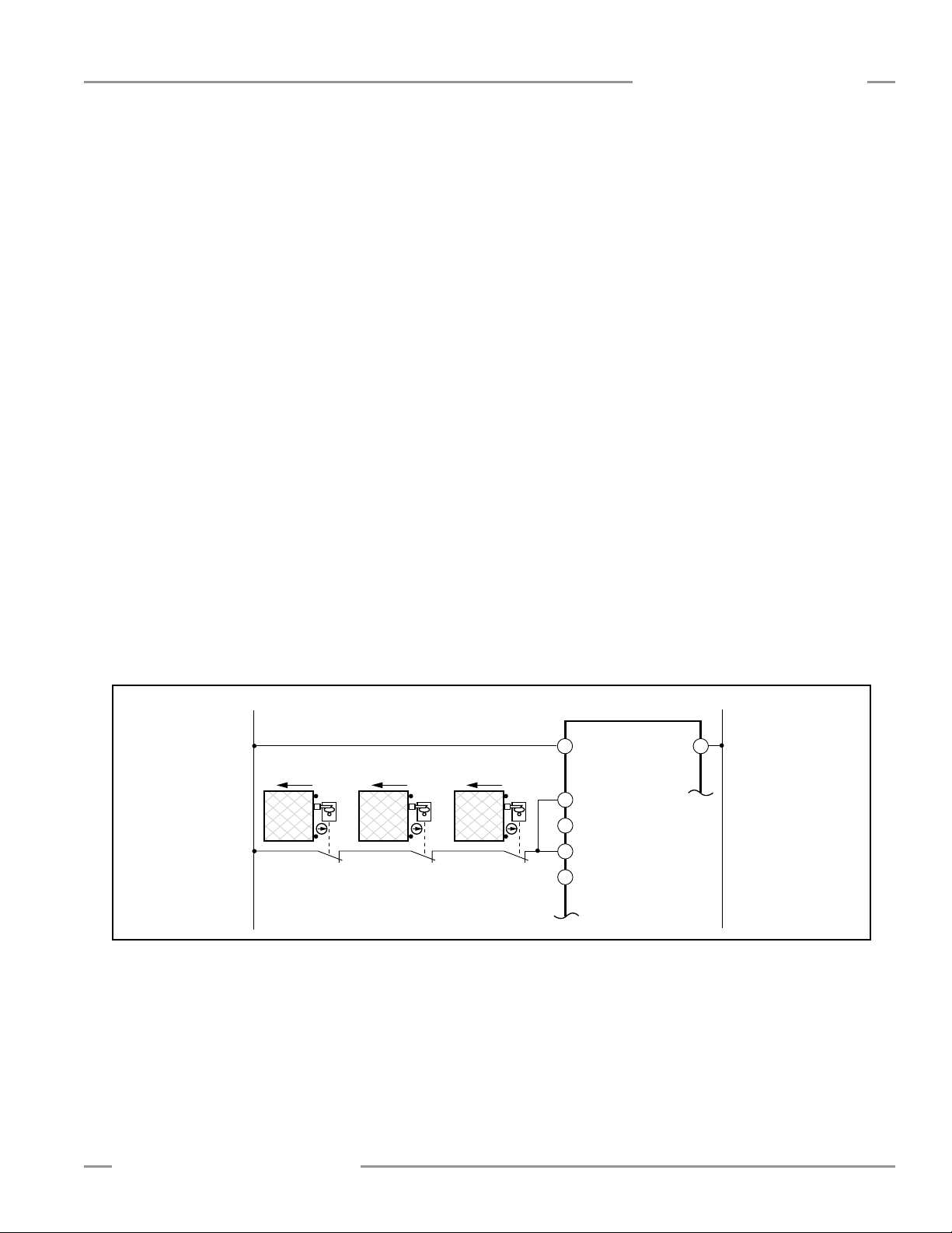
MMD-TA-11B / MMD-TA-12B Muting Module
Open
(a)
(b)
(c)
MMD-TA-..B
A1
0V dc+24V dc
A2
X6
X5
X8
S12
S11
S22
(d)
X7S21
MSSI or SSI
OpenOpen
Instruction Manual
The systems in either scenario do not inherently comply with
the safety standard requirements of detecting single faults
and preventing the next cycle. In multiple-guard systems
using series-connected safety switches, it is important to
periodically check the functional integrity of each interlocked
guard individually. Operators, maintenance personnel, and
others associated with the operation of the machine must
be trained to recognize such failures and be instructed to
correct them immediately.
Open and close each safeguard separately while verifying that
the Module outputs operate correctly throughout the check
procedure. Follow each safeguard closure with a manual reset, if
needed. If a contact set fails, the Module will not enable its reset
function. If the Module does not reset, a switch may have failed;
that switch must be immediately replaced.
This check must be performed and all faults must be cleared, at
a minimum, during periodic checkouts. If the application can
not exclude these types of failures and such a failure could
result in serious injury or death, then the series connection
of safety switches must not be used.
System Installation
Category 2
A single-channel interlocked guard application typically provides
a category 2 level of circuit performance, because a short circuit
could cause the loss of the safety function. The principle of fault
exclusion must be incorporated into the design and installation
to either eliminate, or reduce to an acceptable (minimal) level of
risk, the possibility of undetected faults or failures that can result
in the loss of the safety function.
Figure 3-19. MSSI or SSI Category 2 interfacing: positive opening
Banner Engineering Corp. • Minneapolis, U.S.A.
www.bannerengineering.com • Tel: 763.544.3164
P/N 116390 rev. C 27
Page 30
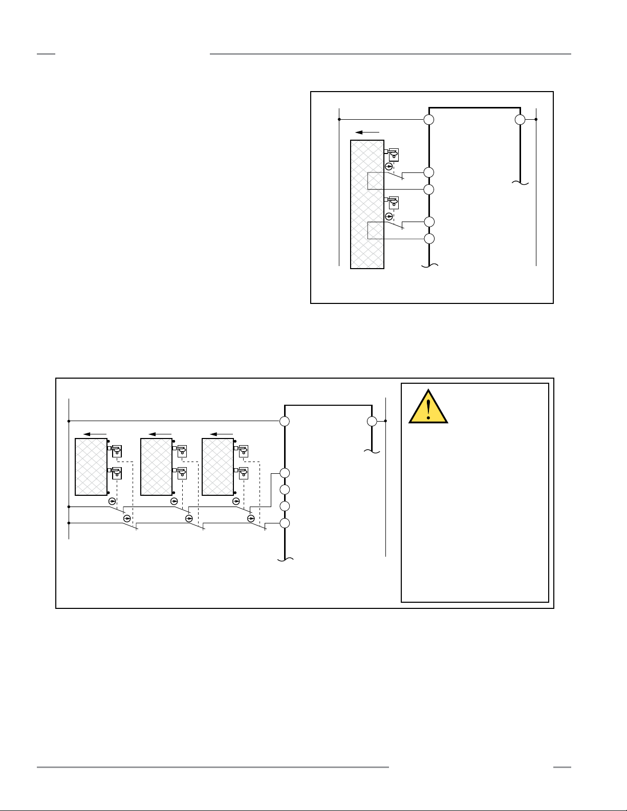
System Installation
Open
(a)
(b)
(c)
(d)
MMD-TA-..B
A1 A2
X6
X5
X8
X7
S12
S11
S22
S21
MSSI or SSI
+24V dc 0V dc
(a)
(b)
(c)
MMD-TA-..B
A1
0V dc+24V dc
A2
X6
X5
X8
S12
S11
S22
(d)
X7S21
MSSI or SSI
Open Open Open
Category 3
A dual-channel hookup switching +24V dc is typically a category
3 application, because a single failure does not result in a loss
of safety. Loss of the switching action in one channel is detected
by the actuation of opening and closing the guard, allowing
the monitoring function of the MSSI or SSI inputs to detect the
discrepancy between the channels. However, a short circuit
between input channels or safety outputs may not be detected.
It should be noted that an accumulation of faults may cause the
loss of the safety function.
The principle of fault exclusion must be incorporated into the
design and installation to either eliminate, or reduce to an
acceptable (minimal) level of risk, the possibility of undetected
faults or catastrophic failures that could result in the loss of the
safety function.
Category 4
The self-monitoring MSSI or SSI inputs can be interfaced to
achieve a category 4 application. The principle of fault exclusion
must be incorporated into the design and installation to either
eliminate, or reduce to an acceptable (minimal) level of risk, the
possibility of catastrophic failures/faults that could result in the
loss of the safety function.
MMD-TA-11B / MMD-TA-12B Muting Module
Instruction Manual
NOTE: Two independently mounted positive-opening switches
per guard.
Figure 3-21. SSI Category 4 interfacing: positive-opening
interlocking switch(es)
NOTE: The interface is still considered a category 3 application if the hookup of each
channel is a closed loop (S11 to S12 and S21 to S22) due to the possibility of a
“series failure.” See warning at right.
Figure 3-20. MSSI or SSI Category 3 interfacing: Positive-opening Interlocking switch(es)
WARNING . . .
Series Connection
of Safety Switches
When monitoring multiple guards
with a series connection of multiple
safety interlock switches, a single
failure may be masked or not
detected at all.
When such a configuration
is used, procedures must be
performed regularly to verify
proper operation of each switch.
See “Monitoring Series-Connected
Safety Switches”
(page 26) for more information.
Failure to do so could result in
serious injury or death.
28 P/N 116390 rev. C
Banner Engineering Corp. • Minneapolis, U.S.A.
www.bannerengineering.com • Tel: 763.544.3164
Page 31
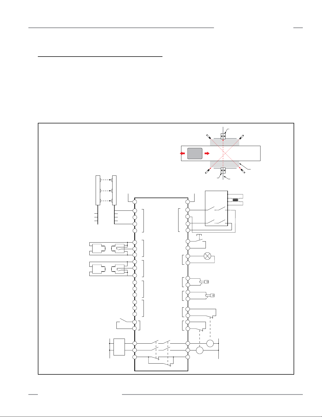
MMD-TA-11B / MMD-TA-12B Muting Module
+
A1
Z21
M1
M1PNP
-
+
PNP
-
+
NPN
-
+
NPN
-
+
+24V dc
EDM1
Safety Mat
Monitor Module
(or Light Screen
Controller)
4-wire Safety Mat
(or horizontally-mounted
Safety Light Screen)
Machine Interface
(see Figures 3-20
through 3-24)
a
b
c
d
EDM2
L2L1
K1A K2A
K1B
K1C
K2B
K2C
Override A
Mute
Lamp
(indicator)
Override B
X9
X10
X11
X12
A2
X6
X5
X8
X7
Y1
Y2
Y3
Y4
X1
X2
X3
X4
32
23
24
31
14
MPCE1
Reset
13
Machine
Control
Circuits*
SSI
MPCE2
0V dc
Z23
M3
M3
Z13
Z22
M2
Z24
M4 M4
a
MSSI
OSSD1
OSSD2
b
0V dc
Ground
+24V dc
0V dc
Ground
+24V dc
3-Beam
EZ-SCREEN Grid
(see note above)
c
d
Mute
Enable
(optional)
MMD-TA-11B
Z14
X13
X14
S12
S11
S22
S21
+
-
+
-
+
-
+
-
Z11
M2
Z12
Carrier
Basket
Safe Area
(free movement of personnel)
Hazardous Area
(protected from personnel entry)
Hard Guarding
Safety Mat (or
Horizontal-Mounted
Safety Light Screen)
M1
M2
EZ-SCREEN Grid
Receiver
EZ-SCREEN Grid
Emitter
Instruction Manual
System Installation
3.5.6.5 SSI Supplemental Safety System Hookup
A variety of safety systems can be interfaced with the MSSI
and the SSI. Each safety application has a unique set of
application requirements. The user is responsible to ensure
proper installation and use, and that all relevant standards and
regulations are complied with. Figure 3-22 shows a generic
example of the flexibility of the SSI.
Entry/Exit Application with a Multiple-Beam Safety System
(Muted) and a Safety Mat System: see Appendix B for more
NOTE: Depending on the application, the 3-beam EZ-SCREEN Grid
system shown typically would be configured for Trip Output
(Automatic Reset). The Muting Module’s manual reset would be
used to reset the system in the event of a stop command being
sent to the machine interface. This allows the EZ-SCREEN to be
interrupted as materials pass through during a muted condition,
without requiring a reset each time a blocked condition occurs.
information. This application is widely used in a variety of
situations, including manufacturing cells, robotic cells, palletizers,
and de-stackers. One of the many requirements of this muting
application is that it must not be possible for personnel to walk
in front of, behind, or next to the muted object (e.g., the carrier
basket) without being detected and stopping the hazardous
motion.
Figure 3-22 shows how supplemental safeguarding (such as
a safety mat system or horizontal safety light screen) can be
interfaced to prevent personnel from entering the hazardous
area during a mute condition.
Figure 3-22. Interfacing supplemental safeguarding to prevent personnel from entering the hazardous area during the mute
Banner Engineering Corp. • Minneapolis, U.S.A.
www.bannerengineering.com • Tel: 763.544.3164
P/N 116390 rev. C 29
Page 32

System Installation
MMD-TA-11B / MMD-TA-12B Muting Module
Instruction Manual
3.6 Machine Interface – Initial Hookup and Checkout
Model MMD-TA-11B provides two normally open safety relay
output contacts (13−14 and 23−24) to hook up external MPCE1
and MPCE2 (see Figures 3-27 and 3-28).
Model MMD-TA-12B provides two PNP solid-state safety
outputs, OSSD1 and OSSD2 (Y5−Y6 and Y7−Y8) see Figures
3-24, 3-25, and 3-26.
For monitoring external devices (both models), normally closed
contacts of these devices must be hooked up to EDM #1
(Y1−Y2) and EDM #2 (Y3–Y4).
Before proceeding, ensure that power has been removed from
machine or ensure that power is not available to the machine
controls or actuators, and ensure that the machine control
(MPCEs) are not connected to or controlled by the OSSD or
relay safety outputs at this time. Permanent connections will be
made after Module initial checkout (see Section 3.7).
Verifying System Operation
The initial checkout procedure must be performed by a Qualified
Person (see Warning, page 12). It must be performed only
after configuring the Module and after properly installing and
configuring the safety systems connected to its MSSI and the
SSI inputs (per Section 3).
The initial checkout procedure is performed on two occasions:
• To ensure proper installation when the System is first installed,
and
• To ensure proper System function whenever any maintenance
or modification is performed on the System or on the machinery
being guarded by the System. (See Section 6.1 for a schedule
of required checkouts.)
For the initial checkout, the Muting Module and associated safety
systems must be checked without power being available to the
guarded machine. Final interface connections to the guarded
machine cannot take place until these systems have been
checked out.
Verify that:
• Power has been removed from (or is not available to) the
guarded machine, its controls or actuators;
• The machine control circuit is not connected to the OSSD
outputs at this time (permanent connections will be made
following this initial checkout), and that the OSSD leads are
isolated (i.e. not shorted together, not shorted to power or
ground);
• EDM has been configured for No Monitoring (SW4 = OFF or 2
CH) and EDM #1 (Y1−Y2) and EDM #2 (Y3−Y4) are jumpered;
• Other than EDM and Mute Enable, verify proper Module DIP
switch configuration for your application; and
• All input connections have been made per appropriate sections
for the Mute Input Devices (M1−M4), SSI, MSSI, Manual Reset
Switch, Mute Lamp, AUX Output, and Override Input.
This will allow the Muting Module and the associated safety
systems to be checked out, by themselves, before permanent
connections are made to the guarded machine.
3.6.1 Temporary Power and Initial Checkout
1. Connection of system DC power is at terminals A1
(+24V dc) and A2 (0V dc), see Section 3.4 and Figure 3-4.
All wiring must comply with NEC and local wiring codes.
2. Leaving power to the guarded machine OFF, power up the
Module and the safety systems connected to the MSSI and
the SSI inputs.
3. Perform system checkout procedures for the external
safety systems connected to the MSSI and SSI inputs as
described by the appropriate manuals. Do not proceed
further until all checkout procedures are completed
successfully and all problems have been corrected.
4. Verify that the external safety systems are providing a
Green/Go signal to the MSSI and SSI inputs (i.e., Banner
OSSD sourcing signal or a closed contact connected to
the “Signal” pin of each interface). Verify that the green
Channel indicators are ON.
NOTE: If the SSI is not to be used, terminals X5−X6 and X7−X8
must be jumpered (factory default). Do not short Channel
A to Channel B. See Section 3.5.6.
Auto Reset Configuration: Verify that the Green status
5.
LED is ON, indicating that the OSSD outputs are ON, and
that a “—” appears on the Diagnostic Display. If not, or if
the Red status indicator begins to flash at any time, refer to
Section 5 for troubleshooting information.
Manual Reset Configuration: Verify that the Yellow status
LED is flashing to indicate that a reset is being requested,
and that a “—” appears on the Diagnostic Display. If not, or
if the Red status indicator begins to flash at any time, refer
to Section 5 for troubleshooting information.
Perform a manual reset by closing the Reset input for
at least 1/4 second, but not longer than 2 seconds, and
then reopening the contact. Verify that the Green status
indicator comes on steady. The Module OSSD outputs
should be ON at this time.
6. Cycle the MSSI and the SSI (if used) individually and
ensure that the Green status indicator goes OFF, and that
a reset is possible after the interface is closed.
If any of these checks fail, do not attempt to use the system
until the reason for the failure(s) is identified and corrected.
30 P/N 116390 rev. C
Banner Engineering Corp. • Minneapolis, U.S.A.
www.bannerengineering.com • Tel: 763.544.3164
Page 33

MMD-TA-11B / MMD-TA-12B Muting Module
Instruction Manual
System Installation
If the Muting function is not used, proceed to Section 3.7.
During the initial checkout procedure of the Muting feature, if
possible, verify that the power has been removed or is otherwise
not available to the machine actuators responsible for hazardous
motion. At all times ensure that personnel are not exposed to
any hazard.
7. Mute the System by blocking (or activating) both mute
devices (typically M1 and M2) simultaneously (within 3
seconds).
8. If used, verify that the Mute indicator comes ON. If not,
check the indicator and its wiring, and check the Diagnostic
Display for error codes.
9. Generate a stop command from the safeguarding device
connected to the MSSI (e.g., interrupt the defined area of
a safety light screen). Verify that MSSI Channel A and B
indicators go OFF, but the Green status indicator remains
ON.
NOTE: If the 30- or 60-second Backdoor Timer feature is
selected, the Diagnostic Display will begin to count down
in seconds. If the 30-minute Backdoor Timer feature is
selected, the timer countdown is in minutes. A flashing
dash will appear on the display if the Backdoor Timer is
OFF (infinite).
10. Clear the Stop command (before the Backdoor Timer
expires) and verify that the MSSI Channel A and B
indicators come ON. Clear (deactivate) the mute devices
before the Backdoor Timer expires and verify the Mute
indicator goes OFF. The Green status indicator should
remain ON.
3.7 Permanent Hookup to the Guarded Machine
OSSD and EDM Connections and Electrical Interface
Supply power, the external reset switch, and other inputs (as
required by each application) should be previously connected by
this point. The final connections to be made are:
• Mute enable,
• EDM hookup,
• OSSD outputs,
• FSD interfacing, and
• MPCE connections.
WARNING . . . Shock Hazard
Always disconnect power from the Safety
System and the guarded machine before
making any connections or replacing any component.
Use extreme caution to avoid electrical shock at all times.
Serious bodily injury or death could result.
WARNING . . . Proper Wiring
The generalized wiring configuration shown
in Figures 3-24, 3-25, 3-26, 3-27 and 3-28
are provided only to illustrate the importance of proper
installation. The proper wiring of the Safety system to any
particular machine is the sole responsibility of the installer
and end user.
11. Verify that it is not possible for a single individual to
initiate a mute condition by triggering the mute devices
(for example, by blocking both photoelectric beams or
actuating both switches) and being able to pass through the
safeguard without being detected and without issuing a stop
command to the machine. Do not expose any individual to
hazard while attempting to mute the system.
12. Verify that it is not possible for personnel to pass in front of,
behind, or next to the muted object without being detected
and without issuing a stop command to the machine.
13. If one-way (directional) muting has been selected, verify
that the system can not be muted by blocking (or activating)
M3−M4 before M1−M2. Do not expose any individual to
hazard while attempting to mute the system.
If all checks have been verified, proceed to Section 3.7. If
any of these checks fail, do not attempt to use the system
until the reason for the failure(s) is identified and corrected.
Banner Engineering Corp. • Minneapolis, U.S.A.
www.bannerengineering.com • Tel: 763.544.3164
P/N 116390 rev. C 31
Page 34

System Installation
A1
X13
+24V dc
0V dc
0V dc
or
Machine Control
X14
MMD-TA-..B
A2
A1
X13
+24V dc+24V dc
0V dc
0V dc
Sensor or PLC
Optional Hookup
Semiconductor
PNP output
X14
MMD-TA-..B
A2
MMD-TA-11B / MMD-TA-12B Muting Module
Instruction Manual
3.7.1 Mute Enable Hookup
The Module provides a Mute Enable input (“ME,” X13−X14) for
the connection of a potential free contact (see Section 1.12).
Mute Enable gives the user the ability to “frame” or create a
“window of opportunity” when a mute can occur. When
configured, the Mute Enable input is a contact that must be
closed before the safeguard can be muted. After the safeguard
is muted, opening of the Mute Enable input has no effect, but it
must be re-closed before the safeguard can be muted again.
To hook up a device (sensor or PLC output) with a solid state
output, see optional hookup in Figure 3-23.
If Mute Enable is not to be used, leave the factory-installed
jumper between X13–X14.
3.7.2 External Device Monitoring (EDM) Hookup
The Module provides connection terminals for the External
Device Monitoring input (EDM #1—Y1−Y2 and EDM #2—
Y3−Y4). External Device Monitoring must be wired in one of
three configurations:
• One-Channel Monitoring — SW4 Banks A and B = ON or 1 CH
(see Figures 3-26 and 3-28). NOTE: EDM #2 input must be left
open.
• Two-Channel Monitoring — SW4 Banks A and B = OFF or 2 CH
(see Figures 3-24, 3-25, and 3-27).
• No Monitoring — SW4 Banks A and B = OFF or 2 CH
NOTE: Terminal Y1 of EDM #1 must be jumpered to Y3 of
EDM #2.
After the initial checkout has been successfully completed, the
EDM configuration that disabled the monitoring function must
be properly reconfigured. The External Device Monitoring inputs
then must be properly connected to the closed monitoring
contacts of the MPCEs (see Section 1.10). Refer to the NOTICE
Regarding MPCE Monitoring Hookup, below, and Figures 3-24,
3-25, 3-26, 3-27, and 3-28.
Figure 3-23. Mute Enable hookup
CAUTION . . . EDM Configuration
If the application does not require this function,
the terminal Y1 of EDM #1 must be jumpered to
Y3 of EDM #2 (see Section 3.7.2). It is the user’s responsibility
to ensure that this does not create a hazardous situation.
NOTICE Regarding External Device Monitoring Hookup
It is strongly recommended that one normally closed,
forced-guided, monitoring contact of each MPCE or external
device be wired in order to monitor the state of the MPCEs
(as shown in Figures 3-24 to 3-28). If this is done, proper
operation of the MPCEs will be verified. MPCE monitoring
contacts must be used in order to maintain control reliability.
32 P/N 116390 rev. C
Banner Engineering Corp. • Minneapolis, U.S.A.
www.bannerengineering.com • Tel: 763.544.3164
Page 35

MMD-TA-11B / MMD-TA-12B Muting Module
Instruction Manual
System Installation
3.7.3 OSSD Output Connections
Both the output signal switching device (OSSD) outputs must
be connected to the machine control such that the machine’s
safety related control system interrupts the circuit or power to the
machine primary control element(s) (MPCE), resulting in a nonhazardous condition. This applies equally to the safety relays of
the model MMD-TA-11B and the solid-state output of the model
MMD-TA-12B.
Final switching devices (FSDs) typically accomplish this when
the OSSDs go to an OFF state. See Figure 3-24.
Refer to the output specifications (Section 2) and Warning below
before making OSSD connections and interfacing the Muting
Module to the machine.
WARNING . . . OSSD Interfacing
To ensure proper operation, the Muting Module
output parameters and machine input parameters
must be considered when interfacing the Muting Module solidstate OSSD outputs to the machine inputs.
Machine control circuitry must be designed so that:
• The maximum cable resistance value between the Muting
Module solid-state safety outputs and the machine inputs is
not exceeded,
• The Muting Module solid-state safety output maximum
OFF-state voltage does not result in an ON condition, and
• The Muting Module solid-state safety output maximum
leakage current, due to the loss of 0V, will not result in an
ON condition.
Failure to properly interface the OSSD outputs to the
guarded machine could result in serious bodily injury or
death.
3.7.4 FSD Interfacing Connections
Final switching devices (FSDs) can take many forms, though the
most common are forced-guided (mechanically linked) relays
or Interfacing Modules. The mechanical linkage between the
contacts allow the device to be monitored by the external device
monitoring circuit for certain failures.
Dependent on the application, the use of FSDs can facilitate
controlling voltage and current that differs from the OSSD
outputs of the Module. FSDs can also be used to control an
additional number of hazards by creating multiple safety stop
circuits.
Safety (Protective) Stop Circuits
A safety stop allows for an orderly cessation of motion or
hazardous situation for safeguarding purposes, which results
in a stop of motion and removal of power from the MPCEs
(assuming this does not create additional hazards). A safety stop
circuit typically comprises of a minimum of two normally open
contacts from forced-guided (mechanically linked) relays, which
are monitored to detect certain failures such that the loss of the
safety function does not occur (i.e. external device monitoring).
Such a circuit can be described as a “safe switching point.”
Typically, safety stop circuits are either single channel (a series
connection of at least two N.O. contacts); or dual channel (a
parallel connection of two N.O. contacts). In either method, the
safety function relies on the use of redundant contacts to control
a single hazard, so that if one contact fails ON, the second
contact will arrest the hazard and prevent the next cycle from
occurring.
Interfacing safety stop circuits must be wired so that the safety
function can not be suspended, overridden, or defeated, unless
accomplished in a manner at the same or greater degree of
safety as the machine’s safety-related control system that
includes the Module.
Banner Engineering Corp. • Minneapolis, U.S.A.
www.bannerengineering.com • Tel: 763.544.3164
The normally open outputs from an IM-T-9A or -11A interfacing
module are a series connection of redundant contacts that form
safety stop circuits and can be used in either single-channel or
dual-channel control methods. (See Figures 3-25 and 3-26.)
P/N 116390 rev. C 33
Page 36

System Installation
MMD-TA-11B / MMD-TA-12B Muting Module
Instruction Manual
Dual-Channel Control
Dual-channel (or two-channel) control has the ability to
electrically extend the safe switching point beyond the FSD
contacts. With proper monitoring (i.e., EDM), this method of
interfacing is capable of detecting certain failures in the control
wiring between the safety stop circuit and the MPCEs. These
failures include a short-circuit of one channel to a secondary
source of energy or voltage, or the loss of the switching action
of one of the FSD outputs. The result could lead to the loss of
redundancy or a complete loss of safety if not detected and
corrected.
The possibility of a failure to the wiring increases as the physical
distance between the FSD safety stop circuits and the MPCEs
increase, as the length or the routing of the interconnecting wires
increases, or if the FSD safety stop circuits and the MPCEs are
located in different enclosures. Thus, dual-channel control with
EDM monitoring should be used in any installation where the
FSDs are located remotely from the MPCEs.
Single-Channel Control
Single-channel (or one-channel) control, as mentioned, uses a
series connection of FSD contacts to form a safe switching point.
After this point in the machine’s safety-related control system,
failures can occur that would result in the loss of the safety
function (e.g., a short-circuit to a secondary source of energy or
voltage).
Thus, this method of interfacing should only be used in
installations where FSD safety stop circuits and the MPCEs are
physically located within the same control panel, adjacent to
each other, and are directly connected to each other; or where
the possibility of such a failure can be excluded. If this can not
be achieved, then two-channel control should be used.
Methods to exclude the possibility of these failures include, but
are not limited to:
• Physically separating interconnecting control wires from each
other and from secondary sources of power.
• Routing interconnecting control wires in separate conduit, runs,
or channels.
• Routing interconnecting control wires with low voltage or neutral
that can not result in energizing the hazard.
• Locating all elements (modules, switches, devices under
control, etc.) within the same control panel, adjacent to each
other, and directly connected with short wires.
• Properly installing multi-conductor cabling and multiple wires
that pass through strain-relief fittings. Over-tightening of a
strain-relief can cause short-circuits at that point.
• Using positive-opening or direct-drive components installed and
mounted in a positive mode.
3.8 Commissioning Checkout
After power is connected to the Muting Module, the EDM has
been properly configured, and the OSSD outputs have been
connected to the machine to be guarded, the operation of the
Muting Module with the guarded machine must be verified before
the combined system may be put into service. To do this, a
Qualified Person must perform the Commissioning Checkout
Procedure described in Section 6.2.
34 P/N 116390 rev. C
Banner Engineering Corp. • Minneapolis, U.S.A.
www.bannerengineering.com • Tel: 763.544.3164
Page 37

MMD-TA-11B / MMD-TA-12B Muting Module
A1
+24V dc 0V dc
EDM1
EDM2
OSSD1
OSSD2
0V
0V
MMD-TA-12B
Y5
Y6
Y7
Y8
A2
Y1
Y2
Y3
Y4
FSD1
FSD2
+
+
Single-Channel
Safety Stop Circuit
Dual-Channel
Safety Stop Circuit
Instruction Manual
NOTE: Do not exceed OSSD maximum load
capacitance specifications.
System Installation
WARNING . . .
Use of Transient
Suppressors
Transient suppressors are
recommended. They MUST be
installed across the coils of
the machine control elements.
NEVER install suppressors
directly across the outputs
of the Module! It is possible
for suppressors to fail as
a short circuit. If installed
directly across the contacts of
the Module, a short-circuited
suppressor will create an unsafe
condition.
WARNING . . .
OSSD Interfacing
To ensure proper
operation, the Muting Module
output parameters and machine
input parameters must be
considered when interfacing the
Muting Module solid-state OSSD
outputs to the machine inputs.
WARNING . . . Proper Wiring
The generalized wiring configurations shown are provided only
to illustrate the importance of proper installation. The proper
wiring of the Muting Module to any particular machine is solely the
responsibility of the installer and end user.
CAUTION . . . Shock Hazard
Always disconnect all power from the Muting Module and the
guarded machine before making any connections or replacing any
Figure 3-24. Generic machine interface hookup: module model MMD-TA-12B, FSD with Two-Channel EDM
component. Use extreme caution to avoid electrical shock at all
times. Serious bodily injury or death could result.
See Section 3.7.4 on interfacing of safety stop circuits
Machine control circuitry must be
designed so that:
• The maximum cable resistance
value between the Muting Module
solid-state safety outputs and the
machine inputs is not exceeded,
• The Muting Module solid-state
safety output maximum
OFF-state voltage does not result
in an ON condition, and
• The Muting Module solid-state
safety output maximum leakage
current, due to the loss of 0V, will
not result in an ON condition.
Failure to properly interface the
OSSD outputs to the guarded
machine could result in serious
bodily injury or death.
Banner Engineering Corp. • Minneapolis, U.S.A.
www.bannerengineering.com • Tel: 763.544.3164
P/N 116390 rev. C 35
Page 38
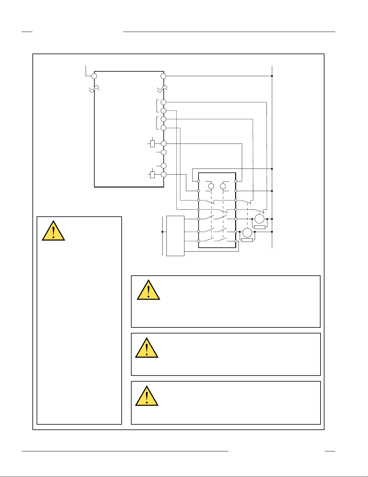
System Installation
+24V dc
A1
+24V dc
0V dc
EDM1
EDM2
OSSD1
OSSD2
0V
0V
MMD-TA-12B
Y5
Y6
Y7
Y8
A2
Y1
Y2
Y3
Y4
+
+
S3
S4
Y3
Y1
13
23
33
Feedback (optional)
Y4
Y2
14
24
34
S1
S2
K2 K1
Machine
Control
MPCE
2
MPCE
1
IM-T-9A
*
*
MMD-TA-11B / MMD-TA-12B Muting Module
Instruction Manual
operation, the Muting Module
output parameters and machine
input parameters must be
considered when interfacing the
Muting Module solid-state OSSD
outputs to the machine inputs.
Machine control circuitry must be
designed so that:
• The maximum cable resistance
• The Muting Module solid-state
• The Muting Module solid-state
Failure to properly interface the
OSSD outputs to the guarded
machine could result in serious
bodily injury or death.
Figure 3-25. Generic machine interface hookup, model MMD-TA-12B: interface module with two-channel EDM
36 P/N 116390 rev. C
WARNING . . .
OSSD Interfacing
To ensure proper
value between the Muting Module
solid-state safety outputs and the
machine inputs is not exceeded,
safety output maximum
OFF-state voltage does not result
in an ON condition, and
safety output maximum leakage
current, due to the loss of 0V, will
not result in an ON condition.
* Installation of transient (arc) suppressors across the coils of MPCE1 and
MPCE2 is recommended (see Warning)
WARNING . . . Use of Transient Suppressors
Transient suppressors are recommended. They MUST be installed
across the coils of the machine control elements. NEVER install
suppressors directly across the outputs of the Module! It is possible for
suppressors to fail as a short circuit. If installed directly across the contacts of
the Module, a short-circuited suppressor will create an unsafe condition.
WARNING . . . Proper Wiring
The generalized wiring configurations shown are provided only
to illustrate the importance of proper installation. The proper
wiring of the Muting Module to any particular machine is solely the
responsibility of the installer and end user.
CAUTION . . . Shock Hazard
Always disconnect all power from the Muting Module and the
guarded machine before making any connections or replacing any
component. Use extreme caution to avoid electrical shock at all
times. Serious bodily injury or death could result.
Banner Engineering Corp. • Minneapolis, U.S.A.
www.bannerengineering.com • Tel: 763.544.3164
Page 39

MMD-TA-11B / MMD-TA-12B Muting Module
A1
+24V dc
+24V dc
0V dc
EDM1
EDM2
OSSD1
OSSD2
0V
0V
MMD-TA-12B
Y5
Y6
Y7
Y8
A2
Y1
Y2
Y3
Y4
+
+
S3
S4
Y3
Y1
13
23
33
Feedback (optional)
Y4
Y2
14
24
34
S1
S2
K2 K1
Machine
Control
MPCE
2
MPCE
1
IM-T-9A
*
*
Instruction Manual
System Installation
WARNING . . .
Use of Transient
Suppressors
Transient suppressors are
recommended. They MUST be
installed across the coils of
the machine control elements.
NEVER install suppressors
directly across the outputs
of the Module! It is possible
for suppressors to fail as
a short circuit. If installed
directly across the contacts of
the Module, a short-circuited
suppressor will create an unsafe
condition.
WARNING . . .
OSSD Interfacing
To ensure proper
operation, the Muting Module
output parameters and machine
input parameters must be
considered when interfacing the
Muting Module solid-state OSSD
outputs to the machine inputs.
Machine control circuitry must be
* Installation of transient (arc) suppressors across the coils of MPCE1 and
MPCE2 is recommended (see Warning)
designed so that:
• The maximum cable resistance
value between the Muting Module
solid-state safety outputs and the
WARNING . . . Proper Wiring
The generalized wiring configurations shown are provided only
to illustrate the importance of proper installation. The proper
wiring of the Muting Module to any particular machine is solely the
responsibility of the installer and end user.
CAUTION . . . Shock Hazard
Figure 3-26. Generic machine interface hookup, model MMD-TA-12B: interface module with one-channel EDM
Banner Engineering Corp. • Minneapolis, U.S.A.
www.bannerengineering.com • Tel: 763.544.3164
Always disconnect all power from the Muting Module and the
guarded machine before making any connections or replacing any
component. Use extreme caution to avoid electrical shock at all
times. Serious bodily injury or death could result.
machine inputs is not exceeded,
• The Muting Module solid-state
safety output maximum
OFF-state voltage does not result
in an ON condition, and
• The Muting Module solid-state
safety output maximum leakage
current, due to the loss of 0V, will
not result in an ON condition.
Failure to properly interface the
OSSD outputs to the guarded
machine could result in serious
bodily injury or death.
P/N 116390 rev. C 37
Page 40

System Installation
A1
+24V dc 0V dc
EDM1
EDM2
L2L1
K1A K2A
K1B
K1C
K2B
K2C
MMD-TA-11B
A2
Y1
Y2
Y3
Y4
32
23
24
31
14
MPCE1
13
Machine
Control
Circuits
MPCE2
A1
+24V dc 0V dc
EDM1
EDM2
L2L1
K1A K2A
K1B
K1C
K2B
K2C
MMD-TA-11B
A2
Y1
Y2
Y3
Y4
32
23
24
31
14
MPCE1
13
Machine
Control
Circuits
MPCE2
MMD-TA-11B / MMD-TA-12B Muting Module
Instruction Manual
Figure 3-27. Generic machine interface hookup, model
MMD-TA-11B: MPCE with 2-channel EDM
WARNING . . . Use of Transient
Suppressors
Transient suppressors are recommended.
They MUST be installed across the coils of the machine
control elements. NEVER install suppressors directly
across the outputs of the Module! It is possible for
suppressors to fail as a short circuit. If installed directly
across the contacts of the Module, a short-circuited
suppressor will create an unsafe condition.
Figure 3-28. Generic machine interface hookup, model
MMD-TA-11B: MPCE with 1-channel EDM
WARNING . . . Proper Wiring
The generalized wiring configurations shown
are provided only to illustrate the importance of
proper installation. The proper wiring of the Muting Module to
any particular machine is solely the responsibility of the
installer and end user.
CAUTION . . . Shock Hazard
Always disconnect all power from the Muting
Module and the guarded machine before
making any connections or replacing any component.
Use extreme caution to avoid electrical shock at all times.
Serious bodily injury or death could result.
38 P/N 116390 rev. C
Banner Engineering Corp. • Minneapolis, U.S.A.
www.bannerengineering.com • Tel: 763.544.3164
Page 41

MMD-TA-11B / MMD-TA-12B Muting Module
Instruction Manual
4. Operating Instructions
Operating Instructions
4.1 Security Protocol
The Module must be mounted inside a lockable enclosure or
cabinet rated IP54 or better, both to protect the Module from
environmental conditions and in order to prevent access by
unauthorized personnel, if required by applicable standards.
The key (or combination) to the enclosure should be kept in
the possession of a Qualified Person and only they should
have access to the configuration switches. A Qualified Person
is defined as an individual who, by possession of a recognized
degree or certificate of professional training, or who, by
extensive knowledge, training, and experience, has successfully
demonstrated the ability to solve problems relating to the subject
matter and work.
4.2 Periodic Checkout Requirements
In addition to the checkouts that are performed by a Qualified
Person or persons at the time that the Module is installed and
put into service, the functioning of the safeguarding and the
machine must be verified on a regular periodic basis to ensure
proper operation. This is absolutely vital and necessary. Failure
to ensure proper operation can lead to serious injury or death.
See Section 6 for checkout schedules and procedures.
WARNING . . .Verify Proper Operation
The Muting Module and safety systems can do
the job for which it was designed only if it and
the machine it guards are operating properly, both separately
and together. It is the user’s responsibility to verify proper
operation, on a regular basis, as instructed in Section 6.
If the Muting Module, safety systems, and the guarded
machine do not perform exactly as outlined in the
checkout procedures, the cause of the problem must be
found and corrected before the system is put back into
service.
Failure to correct such problems can result in serious
bodily injury or death.
4.3 Normal Operation
During normal operation, the Module’s three status indicators
(red, green and yellow) are as shown in Figure 4-1. In addition,
green and yellow indicators adjacent to each of the Module’s
inputs/interfaces come ON to verify an active state of that circuit.
During normal operation, the Diagnostic Display will read “—”
(solid or, if during the mute cycle, flashing). If the 30- or 60second Backdoor Timer feature is selected, the Diagnostic
Display will begin to count down in seconds. If the 30-minute
Backdoor Timer feature is selected, the timer countdown is
in minutes. A flashing dash will appear on the display if the
Backdoor Timer is OFF (infinite). If the Red status indicator
begins to flash, the number that appears in the Display signifies
an error; see Section 5.2 for more information.
See Section 3.5.1 for information on the reset routine.
Waiting
for
Reset*
Red ON ON OFF ON Flashing
Green OFF OFF ON ON OFF
Yellow Flashing ON OFF OFF OFF
* If either MSSI or SSI set to MANUAL, the red Status LED will be OFF at power-up.
Figure 4-1. Muting module status indicator conditions
Output
OFF
Output
ON
Override Lockout
WARNING . . . Power Failures
Power failures or other Module lockout
conditions should always be investigated
immediately by a Qualified Person. A lockout is a definite
indication of a problem and should be investigated at
once. Attempts to continue to operate machinery by
bypassing the Module are dangerous and could result in
serious bodily injury or death.
Banner Engineering Corp. • Minneapolis, U.S.A.
www.bannerengineering.com • Tel: 763.544.3164
P/N 116390 rev. C 39
Page 42

Troubleshooting and Maintenance
5. Troubleshooting and Maintenance
MMD-TA-11B / MMD-TA-12B Muting Module
Instruction Manual
5.1 Troubleshooting Lockout Conditions
A lockout condition causes the OSSD outputs to turn OFF,
sending a stop signal to the guarded machine. A lockout
condition is indicated by the Red status indicator flashing and
an error code appearing in the Diagnostic Display. To clear a
lockout condition, the failure must be corrected, the associated
input must be properly cycled (if fault was due to an input
failure), or a reset routine must be performed.
To perform a reset, close the reset input, hold closed for at least
1/4 second, but no longer than 2 seconds, and then re-open the
input.
5.2 Diagnostic Display
The Module’s Diagnostic Display is useful for monitoring the
safeguarding system and for quickly diagnosing problems. See
Figure 5-1 for a list of status codes and their meanings, along
with recommended corrective actions.
5.3 Effects of Electrical Noise
The Module is designed and manufactured to be highly resistant
to electrical noise and to operate reliably in industrial settings.
However, serious electrical noise may cause a random lockout
condition.
5.4 Repairs
NOTE: Do not attempt any repairs to the Module. It contains no
field-replaceable components. Return the Module to the
factory for warranty repair or replacement.
If it ever becomes necessary to return a Module to the factory,
please do the following:
1. Contact the Banner applications engineering department at
the numbers or address listed on the front cover. They will
attempt to troubleshoot the system from your description of
the problem. If they conclude that a component is defective,
they will issue an RMA (Return Merchandise Authorization)
number for your paperwork, and give you the proper shipping
address.
2. Pack the Module carefully. Damage which occurs in shipping
is not covered by warranty.
WARNING . . . Shut Down Machinery
Before Servicing
The machinery connected to the Module
must not be operating at any time during this
procedure. You may be working close to a hazardous area
of your machinery while servicing the Module. Servicing
the Module while the hazardous machinery is operating
could result in serious bodily injury or death.
Check the following if a noise-related error code is displayed and
other remedies have not cleared the problem:
• Sensor wires or input/output wires routed too close to “noisy”
wiring.
In extreme conditions, it may be necessary to use shielded
cabling or relocate the Module, mute devices, and cabling away
from the source of the noise.
40 P/N 116390 rev. C
Banner Engineering Corp. • Minneapolis, U.S.A.
www.bannerengineering.com • Tel: 763.544.3164
Page 43

MMD-TA-11B / MMD-TA-12B Muting Module
Instruction Manual
Troubleshooting and Maintenance
Status
Error Code
—
(Solid)
—
(Flashing)
31 OSSD Output Error
32 Reset Input Error
33 Module Error
34 MSSI Error*
35 Override Error
36 Mute Lamp Error
37 DIP switch Error
38 EDM 1 Error
System OK
Mute Cycle
- One OSSD is shorted to power/ground
- OSSDs are shorted together
- Reset input shorted/closed
- Excessive EMI/RFI noise
- Internal failure, replace Module
- One or both channels shorted to power or
ground
- Input channels shorted together
- One channel did not open
- Failed simultaneity (>3sec)
- Excessive EMI/RFI noise
- Override input closed at power-up
- Check Override input wiring and connector
- Excessive EMI/RFI noise
- Check/replace lamp (open or short)
- Check wiring and connector
- Check DIP switch settings
- Check DIP switch settings
- Replace Module
- Check wiring
- Check operation of device(s) under control
- Check DIP switch settings
- Switching transition > 200 ms
- Excessive EMI/RFI noise
- EDM remains open > 200 ms after OSSDs
go OFF (if dropout time verification check on)
- EDM not closed at startup
Condition / Error Type /
Action
Status
Error Code
39 EDM 2 Error
- Verify that input 2 is open (single-channel
EDM selected)
- Check wiring
- Check operation of device(s) under control
- Check DIP switch settings
- Excessive EMI/RFI noise
- EDM not closed at startup (Y3–Y4)
40 2-Channel EDM Error
- Check wiring
- Check operation of device(s) under control
- Failed simultaneity between EDM1 and
- Both EDM open > 200 ms after OSSDs go
OFF
- Replace Module
50 Backdoor Timer Expired
- Check muting device operation
- Check muting device wiring
- Check DIP switch settings
- See Section 1.14
51 Mute Timing (Simultaneity) Error
- The second mute device of a pair (M1–M2
- Check muting device operation
- Check wiring
52 Mute Enable Open Error
- ME input was open when a mute cycle was
- Check Mute Enable wiring
61 SSI Input Error*
- One or both channels shorted to power or
- Input channels shorted together
- One channel did not open
- Failed simultaneity (> 3 sec)
- Excessive EMI/RFI noise
Flashing
Mute Lamp
Override Condition
Condition / Error Type /
Action
EDM2 (> 200 ms)
or M3–M4) did not actuate within 3 seconds
of the first device.
attempted
ground
* Fault is cleared by cycling the input from open-to-closed.
Figure 5-1. Troubleshooting conditions, using the Module’s Diagnostic Display
Banner Engineering Corp. • Minneapolis, U.S.A.
www.bannerengineering.com • Tel: 763.544.3164
P/N 116390 rev. C 41
Page 44

Periodic Checkout Procedures
6. Periodic Checkout Procedures
MMD-TA-11B / MMD-TA-12B Muting Module
Instruction Manual
Study each procedure from beginning to end before you start to
make sure that you understand each step. Refer all questions to
the Banner Applications Engineering Department at the address
or numbers listed on the front cover of this manual. Checkouts
must be performed as detailed in Section 6.1 below and results
should be recorded and kept in the appropriate place (e.g., near
the machine, and/or in a technical file).
6.1 Schedule of Checkouts
Initial Checkout: The procedure for initial checkout of the
Module and its interconnected components is described in
Section 3.6. This procedure is performed at installation, and
at any time the System, the guarded machine, or any part of
the application is installed or altered. The procedure must be
performed by a Qualified Person.
Commissioning Checkout: Should be performed after
installation or whenever changes are made to the system (either
a new configuration of the safety system that includes the
MMD-TA-1..B module or changes to the machine). The
procedure must be performed by a Qualified Person. See
Section 6.2.
Daily Checkout: The procedure for “daily” checkout of the
safety system that includes the MMD-TA-1..B module is to
be performed at each shift change or machine setup change,
whenever the System is powered up, at least daily. The
procedure may be performed by a Designated Person or a
Qualified Person. See Section 6.3.
Semi-Annual Checkout: The procedure for initial checkout of
the safety system that includes the MMD-TA-1..B module is to be
performed every six months, following installation of the System.
The procedure must be performed by a Qualified Person. See
Section 6.4.
WARNING . . . Do Not Use Machine
Until System Is Working Properly
If all of these checks cannot be verified, do not
attempt to use the safety system that includes the
MMD-TA-1..B Module/guarded machine until the defect or
problem has been corrected (see Section 5).
Attempts to use the guarded machine under such
conditions could result in serious bodily injury or death.
WARNING . . . Before Applying Power
to the Machine
Verify that the guarded area is clear of
personnel and unwanted materials (such as tools) before
applying power to the guarded machine.
Failure to do so could result in serious bodily injury or
death.
6.2 Commissioning Checkout
Perform this checkout procedure as part of Safeguarding System
installation (after the System has been interfaced to the guarded
machine as described in Sections 3.6 and 3.7), or whenever
changes are made to the System (either a new configuration of
the Module, devices connected to it, or changes to the machine).
A Qualified Person (as defined in the Safety Glossary) must
perform the procedure; checkout results should be recorded and
kept on or near the guarded machine, per OSHA 1910.217(e)(1).
To prepare the Module for this checkout, ensure the
configuration is as it will be during machine operation.
Safeguarding Checkout
1. Examine the guarded machine to verify that it is of a type
and design compatible with the safeguarding system that
has been installed. See page 2.
2. Verify the system(s) checkout procedures for the external
safety systems connected to the MSSI and the SSI inputs
as described by the appropriate manuals. Do not proceed
until all checkout procedures are completed successfully
and all problems have been corrected.
3. Verify that:
• Access to any dangerous parts of the guarded machine
is not possible from any direction not protected by the
safeguarding system, hard guarding, or supplemental
safeguarding, and that
• Supplemental safeguarding and hard guarding, as
described by the appropriate safety standards, are in
place and functioning properly.
4. Verify that the Reset switch is mounted outside the guarded
area, out of reach of anyone inside the guarded area, and
that means of preventing inadvertent use is in place.
5. Examine the electrical wiring connections between the
Module’s OSSD outputs and the guarded machine’s control
elements to verify that the wiring meets the requirements
stated in Section 3.7.
42 P/N 116390 rev. C
Banner Engineering Corp. • Minneapolis, U.S.A.
www.bannerengineering.com • Tel: 763.544.3164
Page 45

MMD-TA-11B / MMD-TA-12B Muting Module
Instruction Manual
Periodic Checkout Procedures
6. Apply power to the Module. Ensure that power to the
guarded machine is OFF. Verify that the external safety
systems are providing a Green/Go signal to the MSSI and
SSI inputs, and that the Green MSSI and SSI indicators (two
pairs of LEDs located near each terminal) are ON. When
configured for Manual Reset, the Yellow status indicator will
be flashing. Perform a manual reset (close the Reset switch
for 1/4 to 2 seconds, then open the switch). Verify that the
Green status indicator is ON steady.
NOTE: A Red flashing status indicator signifies a lockout
condition. Refer to Section 5 for information.
7. In a non-muted condition, generate a stop command from the
safeguarding device connected to the MSSI (e.g. interrupt
the defined area of a safety light screen). Verify that MSSI
Channel A and B and the Green status indicators go OFF. In
order, reset the safeguard and then the Module (in Manual
Reset).
8. Generate a stop command from the safeguarding device
connected to the SSI (e.g., actuate E-stop button). Verify
that SSI Channel A and B and the Green status indicators go
OFF. In order, reset the safeguard and then the Module (in
Manual Reset).
9. Apply power to the guarded machine and verify that the
machine does not start up. Generate a stop command from
the safeguarding device connected to the SSI and the MSSI
in a non-muted condition. Verify that it is not possible for
the guarded machine to be put into motion while either stop
commands are present. In order, reset the safeguard and
then the Module (in Manual Reset).
10. Initiate machine motion of the guarded machine and, while
it is moving, as in step #9 above, generate a stop command
from each safeguarding device. Do not attempt to insert
anything into the dangerous parts of the machine. Upon
issuing the stop command, the dangerous parts of the
machine should come to a stop with no apparent delay.
Upon reset of the safeguard and the Module, verify that the
machine does not automatically restart, and that the initiation
devices must be engaged to restart the machine.
11. Remove electrical power to the Module. All OSSD outputs
should immediately turn OFF, and should not be capable
of turning ON until power is re-applied and a reset is
accomplished.
12. Test the machine stopping response time, using an
instrument designed for that purpose, to verify that it is the
same or less than the overall system response time specified
by the machine manufacturer. (Banner’s Applications
Engineering Department may be able to recommend a
suitable instrument.)
Muting Checkout
13. Verify that the Module has been reset and the Green status
indicator is ON. If the Yellow status indicator is flashing
(indicating the safety system that includes the MMD-TA-1..B
module is waiting for a reset of a latched condition), perform
a manual reset. At any time, if the Red status indicator
begins to flash, a lockout condition exists. Refer to Section
5.1 to determine the cause of the lockout.
During this procedure, at all times ensure that personnel are
not exposed to any hazard.
14. Mute the system by blocking (or activating) both mute
devices (typically M1−M2) simultaneously (within 3
seconds).
15. Verify that the Mute indicator comes ON. If not, check the
indicator and its wiring, verify that the mute enable input is
closed, and check the Diagnostic Display for error codes.
16. Generate a stop command from the safeguarding device
connected to the MSSI; verify the green MSSI channel
indicators are OFF and the Green status indicator is ON.
NOTE: If the Backdoor Timer feature has been selected, the
Diagnostic Display will begin to count down; otherwise a
flashing dash will appear on the display.
17. Clear or reset the safeguard (before the Backdoor Timer
expires) and verify the green MSSI channel indicators
are ON. Clear (deactivate) the mute devices before the
Backdoor Timer expires and verify the Mute indicator goes
OFF. The Green status indicator should remain ON.
18. Verify that it is not possible for a single individual to
initiate a mute condition by triggering the mute devices
(for example, by blocking both photoelectric beams or
actuating both switches) and access the hazard without
being detected and issuing a stop command to the machine
(where the green status indicator goes OFF, and a reset
of the latch condition is required). Do not expose any
individual to hazard while attempting to mute the system.
19. Verify that it is not possible for personnel to pass in front of,
behind, or next to the muted object without being detected
and without issuing a stop command to the machine.
20. If one-way (directional) muting has been selected, verify
that the system can not be muted by blocking (or activating)
M3−M4 before M1−M2. Do not expose any individual to
hazard while attempting to mute the system.
If any of these checks fail, do not attempt to use the safety
system that includes the MMD-TA-1..B module until the
reason for the failure(s) is identified and corrected.
Do not continue operation until the entire checkout
procedure is complete and all problems are corrected.
Banner Engineering Corp. • Minneapolis, U.S.A.
www.bannerengineering.com • Tel: 763.544.3164
P/N 116390 rev. C 43
Page 46

Periodic Checkout Procedures
MMD-TA-11B / MMD-TA-12B Muting Module
Instruction Manual
6.3 Daily Checkout
Perform this checkout procedure at every shift change, powerup and machine set-up change. During continuous machine
run periods, this checkout must be performed at intervals not to
exceed 24 hours. A Designated Person or Qualified Person (as
defined in Section 1.18) must perform the procedure; checkout
results should be recorded and kept on or near the guarded
machine, per OSHA 1910.217(e)(1).
1. Verify that access to the guarded area is not possible from
any area not protected by the safeguards interfaced with
the safety system that includes the MMD-TA-1..B module.
Hard guarding, or supplemental presence-sensing devices
must be installed, wherever needed, to prevent any person
from reaching around the light grid or entering into the
hazard area. Verify that all supplemental guarding devices
and hard guarding are in place and operating properly.
2. Verify that the safeguards interfaced with
that includes the MMD-TA-1..B module have been properly
installed and maintained. See relevant instruction manuals
or data sheets.
3. Verify that it is not possible for a person to access the
hazard(s), undetected by the safeguards interfaced with the
safety system that includes the MMD-TA-1..B module or by
other supplemental guarding (as described in appropriate
standards).
4. Verify that the Reset switch is mounted outside the guarded
area, out of reach of anyone inside the guarded area, and
that the key or other means of preventing inadvertent use is
in place.
5. Verify the system(s) checkout procedures for the external
safety systems connected to the MSSI and the SSI inputs
as described by the appropriate manuals.
6. Initiate machine motion of the guarded machine and, during
the cycle, generate a stop command from the safeguarding
device. Do not attempt to insert anything into the dangerous
parts of the machine. Upon issuing the stop command,
the dangerous parts of the machine should come to a stop
with no apparent delay. Upon reset of the safeguard and
the Module, verify that the machine does not automatically
restart, and that the initiation devices must be engaged to
restart the machine.
the safety system
7. With the guarded machine at rest, generate a stop
command from the safeguarding device(s) and verify that
it is not possible for the guarded machine to be put into
motion.
8. Check carefully for external signs of damage or changes to
the safety system that includes the MMD-TA-1..B module,
the interfaced safeguards, the guarded machine, and their
electrical wiring. Any damage or changes found should be
immediately reported to management.
If any of these checks fail, do not attempt to use the safety
system that includes the MMD-TA-1..B module until the
reason for the failure(s) is identified and corrected.
6.4 Semi-Annual Checkout
Perform this checkout procedure every six months following
the safety system that includes the MMD-TA-1..B module
installation. A Qualified Person (as defined in Section 1.18) must
perform the procedure; checkout results should be recorded and
kept on or near the guarded machine, per OSHA 1910.217(e)(1).
1. Perform the commissioning checkout procedure (Section
6.2) If any decrease in machine braking ability has
occurred, make the necessary clutch/brake repairs, readjust
safeguard separation distance (Ds) appropriately, record
the new Ds calculation, and re-perform the Daily Checkout
procedure.
2. Examine and test the machine primary control elements
(MPCEs) and any intermediary controls (such as interface
modules) to verify that they are functioning correctly and
are not in need of maintenance or replacement.
3. Inspect the guarded machine to verify that no other
mechanical or structural problems could prevent the
machine from stopping or assuming an otherwise safe
condition when signalled to do so by the safety system that
includes the MMD-TA-1..B module.
4. Examine and inspect the machine controls and connections
to the safety system that includes the MMD-TA-1..B module
to verify that no modifications have been made which
adversely affect the System.
If any of these checks fail, do not attempt to use the safety
system that includes the MMD-TA-1..B module until the
reason for the failure(s) is identified and corrected.
44 P/N 116390 rev. C
Banner Engineering Corp. • Minneapolis, U.S.A.
www.bannerengineering.com • Tel: 763.544.3164
Page 47
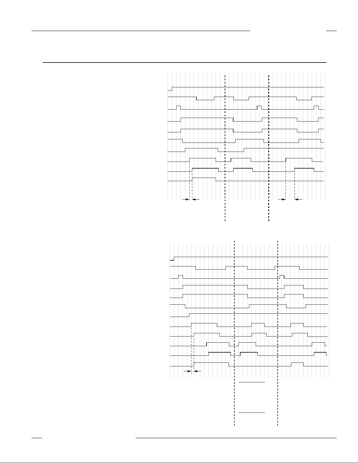
MMD-TA-11B / MMD-TA-12B Muting Module
{
Power
ON
Open
Closed Closed
Closed
Closed
MSSI
Closed
Reset Reset Reset
Open Open Open
Less than
3 seconds
Normal mute cycle
OSSD outputs
remain ON
Mute cycle prevented
due to open
Mute Enable input
Mute cycle prevented
due to simultaneity
not being met
EDM
Open
Mute Enable
M1
Mute
Inputs
Closed
Mute
M2
Mute Cycle
System Reset
More than
3 seconds
OFF
(open)
OFF (open) OFF (open)
ON (closed)
OFF
(open)
OFF (open) OFF (open)
ON (closed)
OSSD Outputs
AUX Outputs
MMD-TA-11B
Closed
One-Way Muting:
{
{
Power ON
OFF
(open)
OFF
(open)
Open
OFF (open) OFF (open)
ON (closed)
OFF (open) OFF (open)
ON (closed)
Closed
MSSI Closed
Reset Reset
Open Open Open
OSSD Outputs
Less than
3 seconds
Normal mute cycle
OSSD outputs
remain ON
Mute cycle drops out
and the OSSD outputs open due
to M3 and M4 not closing before
M1 or M2 open, when the
defined area is blocked.
Since one-way muting has been
selected, M3 and M4 can not
initiate a mute cycle.
EDM
Open
Mute Enable
M1
Mute
Inputs
Closed
Closed
Mute
M2
Mute Cycle
System Reset
M3
Mute
Inputs
M4
Closed
Mute
Mute cycle prevented
due to mute devices
M3 and M4 closing
before M1 and M2.
Two-Way Muting:
A normal mute cycle
would occur.
NOTE: A mute cycle begins 100 ms after the second
mute input becomes active, if all other
conditions are met.
AUX Outputs
MMD-TA-11B
Instruction Manual
Appendix A. Mute Timing Sequences
Muting Sequence with Two Muting Devices
(For example, “X”-pattern Entry/Exit System,
see Figure B-1)
DIP Switch Configuration*:
MSSI Auto or Manual Reset
SSI Auto or Manual Reset
One-Way Muting
. . . . . . . . . . . . SW3 = OFF (1-way)
Two-/One-Channel EDM
Backdoor Timer
. . . . . . . . . . . . .SW5&6 = OFF (30 sec.)
Monitored Muting Lamp
Mute on Power-up
*Both DIP switch banks A and B.
. . . . SW1 = OFF (Manual)
. . . . . SW2 = OFF (Manual)
or ON (Auto)
. . . . . . SW4 = OFF (2 CH)
. . . . . . .SW7 = OFF (Mon)
. . . . . . . . . . . SW8 = OFF (Disable)
Appendix A
Muting Sequence with Four Muting Devices
(For example, an Entry/Exit System using four
photoelectric devices; see Figure B-5)
DIP Switch Configuration*:
MSSI Auto or Manual Reset
SSI Auto or Manual Reset
One-Way Muting
Two-/One-Channel EDM
Backdoor Timer
Monitored Muting Lamp
Mute on Power-up
*Both DIP switch banks A and B.
Banner Engineering Corp. • Minneapolis, U.S.A.
www.bannerengineering.com • Tel: 763.544.3164
. . . . . . . . . . . . SW3 = OFF (1-way)
. . . . . . . . . . . . .SW5&6 = OFF (30 sec.)
. . . . SW1 = OFF (Manual)
. . . . . SW2 = OFF (Manual)
or ON (Auto)
. . . . . . SW4 = OFF (2 CH)
. . . . . . .SW7 = OFF (Mon)
. . . . . . . . . . . SW8 = OFF (Disable)
P/N 116390 rev. C 45
Page 48

Appendix B
Carrier
Basket
Safe Area
(free movement
of personnel)
Hazardous Area
(which is being protected
from personnel entry)
Hard Guarding
Safety Mat or
Horizontally Mounted
Safety Light Screen
M1
M2
Light Screen
Receiver
Light Screen
Emitter
Light Screen
Defined Area
M1
(Receiver
Not
Shown)
M2
(Receiver)
M1
(Emitter)
M2
(Emitter
Not
Shown)
M1
(Emitter)
Light Screen
Defined Area
M1
(Receiver
Not
Shown)
M2
(Receiver)
M2
(Emitter
Not
Shown)
Appendix B. Typical Muting Applications
Entry/Exit Applications
The muting devices must be placed to ensure that the points
that trigger the mute’s start and end are very close to the
safety light screen’s sensing field. This prevents personnel from
following, or being pushed by, the object into the hazardous
area without interrupting the safety light screen before the mute
window opens or at the time the mute window closes.
When two pairs of opposed-mode photoelectrics are used as
muting devices, as shown below, the crossing point of the two
sensing paths must be on the hazardous side of the safety
light screen. The safety light screen will be interrupted before
any personnel would be able to block both beams and mute
the system. The devices should detect the material and not the
pallet or the transport in order to hinder an individual from riding
into the hazardous area.
MMD-TA-11B / MMD-TA-12B Muting Module
Instruction Manual
WARNING . . .
• It must not be possible for an individual to block both
photoelectric beams (dashed diagonal lines in Figure
B-1) and initiate a mute condition. Check the installation
to verify that unintentional muting is not possible. The
“crossing point” of the photoelectric beams must be
located in the hazardous area and not be accessible to
personnel (by reaching over, under, through, or around).
• It must not be possible for personnel to walk in front
of, behind, or next to the muted object (e.g., the carrier
basket) without being detected and stopping the
hazardous motion. Supplemental safeguarding must be
used to prevent personnel from entering the hazardous area
during a mute condition.
46 P/N 116390 rev. C
Figure B-1. “X”-Pattern Entry/Exit system using two pairs of opposed-mode
photoelectric muting devices
Figure B-2. Horizontal photoelectric muting
devices placed at different heights
Figure B-3. Photoelectric muting devices
placed diagonally
Banner Engineering Corp. • Minneapolis, U.S.A.
www.bannerengineering.com • Tel: 763.544.3164
Page 49
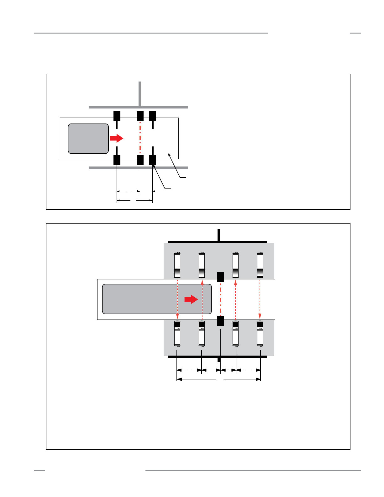
MMD-TA-11B / MMD-TA-12B Muting Module
E
R
A B
C
Carrier
Basket
Light
Screen
M1 M3
M2 M4
A ≥ (speed of line ft/sec) x 0.1 sec.
B ≈ 3" or position must hinder
personnel following muted object
C ≤ Length of carrier basket
– Trapping hazards must be avoided and
clearance requirements complied with.
– Switch actuators can not be so long that they
allow a single person to initiate a
muted condition.
– Polarized-retroreflective (with targets
mounted on carrier) and inductive
proximity sensors could be used in a
similar manner, if an individual can
not ride into the hazardous area.
One-way (directional) muting can be used
in "Exit" applications to reduce the
possibility of intentional defeat.
Hard Guarding
Whisker/Limit
Switches
Transfer Line
R
E
Carrier
Basket
M1
Hard Guarding
M2 M3 M4
Light
Screen
A ≥ (speed of line ft/sec) x 0.1 sec.
B ≈ 3" or position must hinder personnel
following muted object
C ≤ Length of carrier basket
D < (speed of line ft/sec) x 3.0 sec., but beams M1 and M2
must be far enough apart to hinder an individual
from triggering both sensors.
One-way (directional) muting can be used in "Exit" applications to reduce the possibility of intentional defeat.
Safety Mat
D A
C
B D
Instruction Manual
Appendix B
Figure B-4. Entry/exit system using 4 whisker/limit switches as muting devices
Figure B-5. An entry/exit system using four photoelectric sensors as M1, M2, M3, and M4
Banner Engineering Corp. • Minneapolis, U.S.A.
www.bannerengineering.com • Tel: 763.544.3164
P/N 116390 rev. C 47
Page 50

Appendix B
Automated
Door
Hazardous
Area
Light Screen
Emitter
Light Screen
Receiver
M1
M2
M3
M4
Home or Station Applications
The muting devices must be placed to ensure that the safety
light screen is muted only when the hazard does not exist or is
in another area so that personnel are not exposed. The muting
devices must be placed so that if a hazard arises, or the hazard
enters the safeguarded area, the mute will immediately end and
the safeguard will be active once again.
In “home position” muting applications, the light screen is active
only while motion is taking place or a hazard is present, such
as the closing of an automated door. In this example, the door
is interlocked and the machine can not start until the opening
is completely closed. The hazard being guarded by the light
screen is the pinch point caused by the door closing.
M3 and M4 could be two SI-QS75MC safety switches, each
with a single safety contact used for the muting input. M1 and
M2 could be SI-QS90MF safety switches, each with two safety
contacts (one for muting and one for interlocking) and one
monitoring contact for a logic input.
If the light screen is also guarding hazards within the enclosure
when the door is open or preventing cycle initiation, then
switches M3 and M4 would not be used. The door could also be
“locked” by using locking style safety switches, such as the
SI-QM100 or SI-LS42 as M1 and M2.
MMD-TA-11B / MMD-TA-12B Muting Module
Instruction Manual
Figure B-6. A “home position” (door) muting application, using
4 safety switches as muting devices
WARNING . . . User is Responsible
for Safe Application of this Product
The muting application examples described
in Appendix B depict generalized guarding
situations. Every guarding application has a unique set of
application requirements. Extreme care is urged to ensure
that all legal requirements are met and that all installation
instructions are followed.
In addition, any questions regarding safeguarding should
be directed to the factory applications department at the
telephone number or addresses listed on the back cover.
48 P/N 116390 rev. C
Banner Engineering Corp. • Minneapolis, U.S.A.
www.bannerengineering.com • Tel: 763.544.3164
Page 51
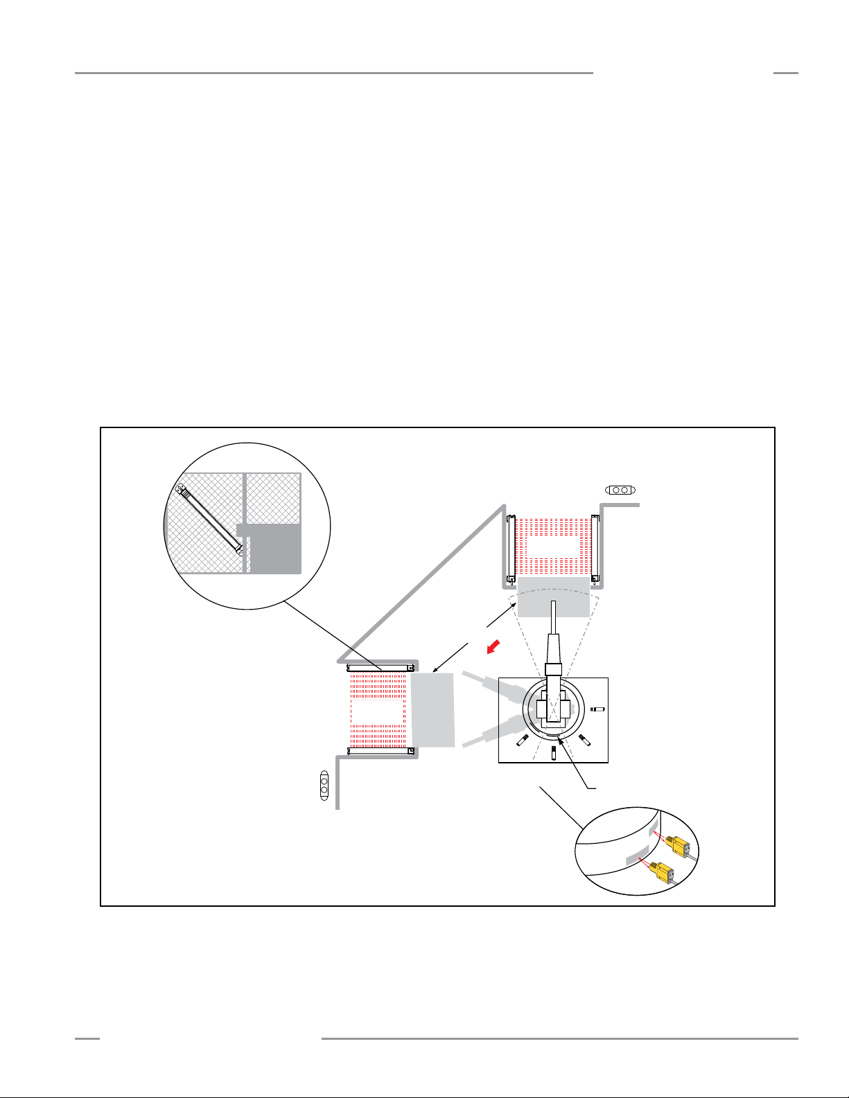
MMD-TA-11B / MMD-TA-12B Muting Module
Angled
Light Screen
Station
"B"
Hard
Guarding
Station
"A"
M1A and M2A
Station "A"
Mute Circuit
M1B and M2B
Station "B"
Mute Circuit
Retroreflective
Targets
Detail B
Station "B"
Run-Bar with
Two-Hand Control,
E-Stop, and
Clamping Manual
Release
Station "A"
Run-Bar
Angled
Light Screen
Station A
Work Envelope
Clamping and
Welding Fixtures
Detail A
Instruction Manual
Appendix B
Robot Load/Unload Station Application
This “station” muting application uses two independent safety
light screen circuits, each with its own muting circuit and
muting devices (e.g. polarized-retroreflective photoelectrics).
The application also includes run bars with two-hand control,
auxiliary controls, and E-Stop. The two-hand control is provided
at each station to safeguard the operator during the momentary
clamping action of the fixture while the safety light screen is
muted.
In this example, the safety light screens are angled
outwards (see Figure B-7, detail A). This provides proper
separation distance from the hazards created by the robot
and the clamping/welding fixtures, while protecting against
the possibility of pass-through hazards. In muting applications
involving an operator, the operator must be continually
detectable by the defined area. This ensures that if a hazard
arises, causing the mute to end while the operator is present,
the safety light screen will immediately issue a stop.
While the robot is at station “A”, the light screen at station “B” is
muted (M1B and M2B are active), allowing the operator to load
or unload without issuing a stop command to the robot. As the
robot moves out of the “A” work envelope (as defined by Station
“B” mute devices, see detail B) the mute discontinues at station
“B”. If the operator is still within the protected area, a stop
command is immediately issued. As the robot moves to the work
envelope of station “B”, the mute devices M1A and M2A activate
and mute the safety light screen at station “A.”
Figure B-7. A robot load/unload application with two-station home-position muting, using polarized retroreflective photoelectrics
as muting devices
Banner Engineering Corp. • Minneapolis, U.S.A.
www.bannerengineering.com • Tel: 763.544.3164
P/N 116390 rev. C 49
Page 52

Appendix B
Muting Sensors and Retroreflective
Targets at Different Heights and
Positions
Load
Conveyor
Unload
Conveyor
Milling
and
Drilling
Operations
M1
Retroreflective
Targets at Each Position
to Initiate a Mute
M2
Defined Area
Hard Guarding
Load
Unload
MMD-TA-11B / MMD-TA-12B Muting Module
Instruction Manual
Turret Table Application
A “Turret Table” application is similar to the Robot Load/Unload
Station muting application, except that any movement of the
table ends the mute. To accomplish this, small retroreflective
targets (or tape) are positioned so that they will initiate the mute
(the sensors must be set to “Light Operate”) only after the table
has finished indexing. (NOTE: The example shows four pairs of
targets, one pair for each position.)
When the table begins indexing again, the polarizedretroreflective photoelectrics immediately “lose sight” of the
targets and end the mute. Since the rotation of the table is the
hazard, the size and positioning of the targets must prevent
muting while motion is taking place.
The top of the emitter and receiver are angled outwards to
maintain proper separation distance while preventing a passthrough hazard. Hard guarding, or other safeguarding, must
be positioned to prevent personnel from reaching through and
accessing any hazard.
Figure B-8. A typical application for turret table inspection or operation station muting, using retroreflective photoelectric sensors
as muting devices
50 P/N 116390 rev. C
Banner Engineering Corp. • Minneapolis, U.S.A.
www.bannerengineering.com • Tel: 763.544.3164
Page 53

MMD-TA-11B / MMD-TA-12B Muting Module
Instruction Manual
Appendix B
Power Press Applications
Muting is allowed on power presses only during the nonhazardous portion of the cycle (e.g. the upstroke), per
OSHA1910.217, ANSI B11.1, B11.2, and B11.3. The mute
permits the insertion or removal of material into the press
that would otherwise block the sensing field of the safety
light screen, causing the press to stop. Muting should not be
confused with “Inch” or “Jog” modes, whose manual selection
may bypass the safety light screen within the machine control.
For the proper application of muting on a power press, at a
minimum, two (or four) independent position switches (such as
cam-operated limit switches, inductive prox sensors, or pressure
switches) must be used to initiate the mute during the nonhazardous portion of the machine cycle. These position switches
would be mute devices M1/M2 (and M3/M4 if used). Typically,
these switches have normally open contacts, which are held (or
actuated) closed during the mute cycle.
These switches must be mounted separately to prevent
misadjustment, misalignment, or a single common mode failure,
which would result in an improper mute cycle or otherwise
unsafe condition. They must be installed so that they can not
be easily defeated or bypassed, and their adjustment should be
under supervisory control.
The two (or four) muting devices must be properly adjusted (or
positioned) so that they close only after the hazard no longer
exists and then open when the cycle is complete (top of stroke)
or when the hazard is again present. If improperly adjusted or
positioned, injury or death could result.
In muting applications involving an operator, all pass-through
hazards must be eliminated so that the operator is continually
detected when in the defined area. This ensures that if a
hazard arises, causing the mute cycle to end while the operator
is present, the safety light screen will immediately issue a
stop. (See pass-through hazard information below.)
A “pass-through hazard” is associated with applications that
allow personnel to pass through a safeguard, which removes or
stops the hazard(s), and then allows the individual to continue
into the hazardous area. Subsequently the individual’s presence
is no longer detected, and the safeguard can not prevent the
start or restart of the machine. A pass-through can be created
by as little as 75 mm (3") space between the defined area and
machine frame. If the safety light screen is muted while the
individual passes through the defined area, a stop command will
not be issued and the hazard cannot be eliminated; the individual
must be detected while entering the safeguarded area and
the hazardous motion must stop immediately. This is typically
accomplished by supplemental safeguarding such as described
in ANSI B11 standards or other appropriate standards.
WARNING . . . Proper Installation
The user has the responsibility to ensure that
all local, state, and national laws, rules, codes,
and regulations in any particular application
are satisfied. It is extremely important to be sure that all
appropriate agency requirements have been met. See inside
back cover for appropriate standards.
If the machine has reversing capability where a hazard is
possible during a muted condition, the control must include
an automatic means through which muting is permitted in the
forward (non-hazardous) direction only. A “Mute Enable” signal
from the machine control, motor drive, or other machine logic, is
a means to assist in meeting this requirement.
Banner Engineering Corp. • Minneapolis, U.S.A.
www.bannerengineering.com • Tel: 763.544.3164
P/N 116390 rev. C 51
Page 54

Glossary of Terms
Glossary of Terms
MMD-TA-11B / MMD-TA-12B Muting Module
Instruction Manual
ANSI (American National Standards Institute): the American
National Standards Institute, an association of industry
representatives that develops technical standards (including
safety standards). These standards comprise a consensus
from a variety of industries on good practice and design. ANSI
standards relevant to application of safety products include
the ANSI B11 Series, and ANSI/RIA R15.06. See “Safety
Standards” on inside back cover.
Auto Power-Up: a safety light screen system feature which,
when switched ON, enables the system to be powered up
(and recover from a power interruption) without requiring a
manual reset. When Auto Power-Up is ON, the safety light
screen controller automatically begins internal diagnostics upon
power-up, and automatically resets the system if it passes the
diagnostic check. When Auto Power-up is OFF, a manual reset
is required.
Blocked Condition: A safety light screen condition, when an
opaque object of sufficient size blocks/interrupts one or more
light screen beams. When a Blocked condition occurs, OSSD1
and OSSD2 outputs simultaneously turn off within the system
response time.
Brake: a mechanism for stopping or preventing motion..
Clutch: a mechanism that, when engaged, transmits torque to
impart motion from a driving member to a driven member.
Control Reliability: A method of ensuring the performance
integrity of a control system. Control circuits are designed and
constructed so that a single failure or fault within the system
does not prevent the normal stopping action from being applied
to the machine when required, or does not create unintended
machine action, but does prevent initiation of successive
machine action until the failure is corrected.
CSA: Canadian Standards Association, a testing agency similar
to Underwriters Laboratories, Inc. (UL) in the United States. A
CSA-certified product has been type-tested and approved by
the Canadian Standards Association as meeting electrical and
safety codes.
Defined Area: the “screen of light” generated between the
emitter and receiver of a safety light screen system. When the
defined area is interrupted by an opaque object of a specified
cross section, a Trip or Latch condition results.
Designated Person: an individual identified and designated
in writing, by the employer, as being appropriately trained
and qualified to perform a specified checkout procedure. (See
Qualified Person.)
Emitter: the light-emitting component of a safety light screen
system, consisting of a row of synchronized modulated LEDs.
The emitter, together with the receiver (placed opposite),
creates a “screen of light” called the defined area.
External Device Monitoring (EDM): a means by which a
safety device (such as a safety light screen) actively monitors
the state (or status) of external devices that may be controlled
by the safety device. A lockout of the safety device will
result if an unsafe state is detected in the external device.
External device(s) may include, but are not limited to: MPCEs,
mechanically linked relays/contactors, and safety modules.
Failure to Danger: a failure which delays or prevents a machine
safety system from arresting dangerous machine motion.
Final Switching Device (FSD): the component of the machine’s
safety-related control system that interrupts the circuit to the
machine primary control element (MPCE) when the output signal
switching device (OSSD) goes to the OFF-state.
FMEA (Failure Mode and Effect Analysis): a testing
procedure by which potential failure modes in a system are
analyzed to determine their results or effects on the system.
Component failure modes that produce either no effect or a
Lockout condition are permitted; failures which cause an unsafe
condition (a failure to danger) are not. Banner safety products
are extensively FMEA tested.
Forced-Guided Contacts: relay contacts that are mechanically
linked, so that when the relay coil is energized or de-energized,
all of the linked contacts move together. If one set of contacts
in the relay becomes immobilized, no other contact of the
same relay will be able to move. The function of forced-guided
contacts is to enable the safety circuit to check the status of
the relay. Forced-guided contacts are also known as “positiveguided contacts,” “captive contacts,” “locked contacts,” or “safety
relays.”
Guarded Machine: The machine whose point of operation is
guarded by the safety light screen system.
Hard Guard: screens, bars, or other mechanical barriers
affixed to the frame of the machine intended to prevent entry
by personnel into the hazardous area(s) of a machine, while
allowing the point of operation to be viewed. The maximum
size of openings is determined by the applicable standard, such
as Table O-10 of OSHA 29CFR1910.217, also called a “fixed
barrier guard.”
Hazardous Area: an area that poses an immediate or
impending physical hazard.
52 P/N 116390 rev. C
Banner Engineering Corp. • Minneapolis, U.S.A.
www.bannerengineering.com • Tel: 763.544.3164
Page 55

MMD-TA-11B / MMD-TA-12B Muting Module
Instruction Manual
Glossary of Terms
Hazard Point: the closest reachable point of the hazardous
area.
Internal Lockout: a Lockout condition that is due to an internal
safety system problem. Generally, indicated by the red Status
indicator LED (only) flashing. Requires the attention of a
Qualified Person.
Key Reset (Manual Reset): a key-operated switch used to
reset a safety light screen system to the ON state following a
Lockout condition. Also refers to the act of using the switch to
reset a safety system from a Latch condition.
Latch Condition: the response of the Safety Outputs (e.g.,
OSSDs) of a safety light screen system when an object equal
to or greater than the diameter of the specified test piece
enters the defined area. In a Latch condition, safety outputs
simultaneously de-energize and open their contacts. The
contacts are held (latched) open until the object is removed from
the defined area and a manual reset is performed. A latching
output is used most often in perimeter guarding applications.
(See Trip Condition.)
Lockout Condition: a safety light screen system condition that
is automatically attained in response to certain failure signals
(an internal lockout). When a Lockout condition occurs, the
safety light screen system’s safety outputs turn OFF, and a
manual reset is required to return the system to RUN mode.
Machine Operator: an individual who performs production work
and who controls operation of the machine.
Machine Primary Control Element (MPCE): an electricallypowered element, external to the safety system, which directly
controls the machine’s normal operating motion in such a way
that the element is last (in time) to operate when machine
motion is either initiated or arrested.
Minimum Object Sensitivity (MOS): the minimum-diameter
object that a safety light screen system can reliably detect.
Objects of this diameter or greater will be detected anywhere in
the defined area. A smaller object can pass undetected through
the light if it passes exactly midway between two adjacent light
beams. Also known as MODS (Minimum Object Detection Size).
See also Specified Test Piece.
Muting: the automatic suspension of the safeguarding function
of a safety device during a non-hazardous portion of the
machine cycle.
OFF State: The state in which the output circuit is interrupted
and does not permit the flow of current.
ON State: The state in which the output circuit is complete and
permits the flow of current.
OSHA (Occupational Safety and Health Administration): a
U.S. Federal agency, Division of the U.S. Department of Labor,
that is responsible for the regulation of workplace safety.
OSSD: Output Signal Switching Device. The safety outputs that
are used to initiate a stop signal.
Pass-Through Hazard: A situation that may exist when
personnel pass through a safeguard (at which point the hazard
stops or is removed), and then continue into the guarded area.
At this point the safeguard may not be able to prevent an
unexpected start or restart of the machine with personnel within
the guarded area.
Point of Operation: the location of a machine where material or
a workpiece is positioned and a machine function is performed
upon it.
Point-of-Operation Guarding: safeguards, such as hard
guards or safety light screens, which are designed to protect
personnel from hazardous machine motion when close to the
machine’s point of operation.
Qualified Person: an individual who, by possession of a
recognized degree or certificate of professional training, or by
extensive knowledge, training, and experience, has successfully
demonstrated the ability to solve problems relating to the subject
matter and work. (See Designated Person.)
Receiver: the light-receiving component of a safety light screen
system, consisting of a row of synchronized phototransistors.
The receiver, together with the emitter (placed opposite),
creates a “screen of light” called the defined area.
Reset: The use of a manually operated switch to restore
the safety outputs to the ON state from a lockout or a Latch
condition.
Self-Checking (Circuitry): a circuit with the capability to
electronically verify that all of its own critical circuit components,
along with their redundant backups, are operating properly.
Banner safety light screen systems and safety modules are selfchecking.
Separation Distance (Safety Light Screen): the minimum
distance required to allow the machine’s hazardous motion
to stop completely, before a hand (or other object) can reach
the nearest hazard point. Measured from the midpoint of the
defined area to the nearest hazard point. Factors that influence
minimum separation distance include the machine stop time,
the light screen system response time, and the light screen
minimum object detection size.
Specified Test Piece: an opaque object of sufficient size used
to block a light beam to test the operation of a safety light
screen system. When inserted into any part of the defined area,
it will place a system into a Trip or Latch condition. Banner
supplies specified test pieces with each system. See also
Minimum Object Sensitivity.
Supplemental Guarding: additional safeguarding device(s) or
hard guarding, used to prevent a person from reaching over,
under, through or around the primary safeguard or otherwise
accessing the guarded hazard.
Banner Engineering Corp. • Minneapolis, U.S.A.
www.bannerengineering.com • Tel: 763.544.3164
P/N 116390 rev. C 53
Page 56

Glossary of Terms
Test Piece: an opaque object of sufficient size used to block a
light beam to test the operation of a safety light screen system.
Trip Condition: the response of the safety outputs (e.g.,
OSSDs) of a safety light screen system when an object equal to
or greater than the diameter of the specified test piece enters the
defined area. In a Trip condition, the OSSDs simultaneously deenergize. A Trip condition clears (resets) automatically when the
object is removed from the defined area. (See Latch Condition.)
TUV (Technischer Überwachungsverein): independent
testing and certification organization providing EMC and product
safety testing, certification, and quality management systems
registration.
UL (Underwriters Laboratory): a third-party organization
that tests products for compliance with appropriate standards,
electrical codes, and safety codes. Compliance is indicated by
the UL listing mark on the product.
MMD-TA-11B / MMD-TA-12B Muting Module
Instruction Manual
54 P/N 116390 rev. C
Banner Engineering Corp. • Minneapolis, U.S.A.
www.bannerengineering.com • Tel: 763.544.3164
Page 57

MMD-TA-11B / MMD-TA-12B Muting Module
Instruction Manual
Notes
Banner Engineering Corp. • Minneapolis, U.S.A.
www.bannerengineering.com • Tel: 763.544.3164
P/N 116390 rev. C 55
Page 58

Notes
MMD-TA-11B / MMD-TA-12B Muting Module
Instruction Manual
56 P/N 116390 rev. C
Banner Engineering Corp. • Minneapolis, U.S.A.
www.bannerengineering.com • Tel: 763.544.3164
Page 59

The list of standards below is included as a convenience for users of this Banner product. Inclusion of these standards does not imply
that the product complies specifically with any standard, other than those listed in the Specifications section of this manual.
SOURCES
OSHA Documents
Superintendent of Documents
Government Printing Office
P.O. Box 371954
Pittsburgh, PA 15250-7954
Tel: (202) 512-1800
http://www.osha.gov
ANSI Accredited Standards
American National Standards Institute (ANSI)
11 West 42nd Street
New York, NY 10036
Tel: (212) 642-4900
http://www.ansi.org
B11 Documents
Safety Director
The Association for Manufacturing
Technology (AMT)
7901 Westpark Drive
McLean, VA 22102
Tel: (703) 893-2900
http://www.mfgtech.org
RIA Documents
Robotics Industries Association (RIA)
900 Victors Way, P.O. Box 3724
Ann Arbor, MI 48106
Tel: (734) 994-6088
http://www.robotics.org
NFPA Documents
National Fire Protection Association
1 Batterymarch Park
P.O. Box 9101
Quincy, MA 02269-9101
Tel: (800) 344-3555
http://www.nfpa.org
Alternate sources for these, plus ISO,
IEC, EN, DIN, and BS Standards:
Global Engineering Documents
15 Inverness Way East
Englewood, CO 80112-5704
Tel: (800) 854-7179
http://www.global.ihs.com
National Standards Systems Network
(NSSN)
25 West 43rd Street
New York, NY 10036
Tel: (212) 642-4980
http://www.nssn.com
Document Center, Inc.
111 Industrial Road, Suite 9
Belmont, CA 94002
Tel: (650) 591-7600
http://www.document-center.com
U.S. Application Standards
ANSI B11.1 Mechanical Power Presses
ANSI B11.2 Hydraulic Power Presses
ANSI B11.3 Power Press Brakes
ANSI B11.4 Shears
ANSI B11.5 Iron Workers
ANSI B11.6 Lathes
ANSI B11.7 Cold Headers and Cold Formers
ANSI B11.8 Drilling, Milling, and Boring
ANSI B11.9 Grinding Machines
ANSI B11.10 Metal Sawing Machines
ANSI B11.11 Gear Cutting Machines
ANSI B11.12 Roll Forming and Roll Bending
Machines
ANSI B11.13 Single- and Multiple-Spindle
Automatic Bar and Chucking Machines
ANSI B11.14 Coil Slitting Machines
ANSI B11.15 Pipe, Tube, and Shape
Bending Machines
OSHA Regulations
OSHA Documents listed are part of: Code
of Federal Regulations Title 29, Parts 1900 to
1910
OSHA 29 CFR 1910.212 General Require-
ments for (Guarding of) All Machines
International/European Standards
ISO/TR 12100-1 & -2 (EN 292-1 & -2) Safety
of Machinery – Basic Concepts, General
Principles for Design
ISO 13852 (EN 294) Safety Distances
. . . Upper Limbs
ISO 13850 (EN 418) Emergency Stop
Devices, Functional Aspects – Principles for
Design
ISO/DIS 13851 (EN 574) Two-Hand Control
Devices – Functional Aspects – Principles for
Design
ISO 13853 (prEN 811) Safety Distances
. . . Lower Limbs
ISO 13849-1 (EN 954-1) Safety-Related
Parts of Control Systems
ISO/DIS 13855 (EN 999) The Positioning of
Protective Equipment in Respect to Approach
Speeds of Parts of the Human Body
ANSI B11.16 Metal Powder Compacting
Presses
ANSI B11.17 Horizontal Extrusion Presses
ANSI B11.18 Machinery and Machine
Systems for the Processing of Coiled Strip,
Sheet, and Plate
ANSI B11.19 Performance Criteria for
Safeguarding
ANSI B11.20 Manufacturing Systems
ANSI B11.21 Machine Tools Using Lasers
ANSI B11.22 Numerically Controlled Turning
Machines
ANSI B11.23 Machining Centers
ANSI B11.24 Transfer Machines
ANSI B11.TR3 Risk Assessment
ANSI/RIA R15.06 Safety Requirements for
Industrial Robots and Robot Systems
ANSI NFPA 79 Electrical Standard for
Industrial Machinery
OSHA 29 CFR 1910.147 The Control of
Hazardous Energy (lockout/tagout)
OSHA 29 CFR 1910.217 (Guarding of)
Mechanical Power Presses
ISO 14121 (EN 1050) Principles of Risk
Assessment
ISO 14119 (EN 1088) Interlocking Devices
Associated with Guards – Principles for
Design and Selection
IEC/EN 60204-1 Electrical Equipment of
Machines Part 1: General Requirements
IEC/EN 61496 Electro-sensitive Protection
Equipment
IEC 60529 Degrees of Protection Provided by
Enclosures
IEC/EN 60947-5-1 Low Voltage Switchgear
– Electromechanical Control Circuit Devices
IEC/EN 60947-1 Low Voltage Switchgear
– General Rules
IEC 61508 Functional Safety
IEC 62061 Machinery Functional Safety
Page 60

WARRANTY: Banner Engineering Corp. warrants its products to be free from defects for one year. Banner Engineering Corp. will repair or replace,
free of charge, any product of its manufacture found to be defective at the time it is returned to the factory during the warranty period. This warranty
does not cover damage or liability for the improper application of Banner products. This warranty is in lieu of any other warranty either expressed or
implied.
P/N 116390 rev. C
Banner Engineering Corp., 9714 Tenth Ave. No., Mpls., MN 55441 • Ph: 763.544.3164 • www.bannerengineering.com • Email: sensors@bannerengineering.com
 Loading...