

Page 1
Gain
Adjustment
Blue (2)
Brown (1)
No
Connection
No
Connection
LED
Indicator
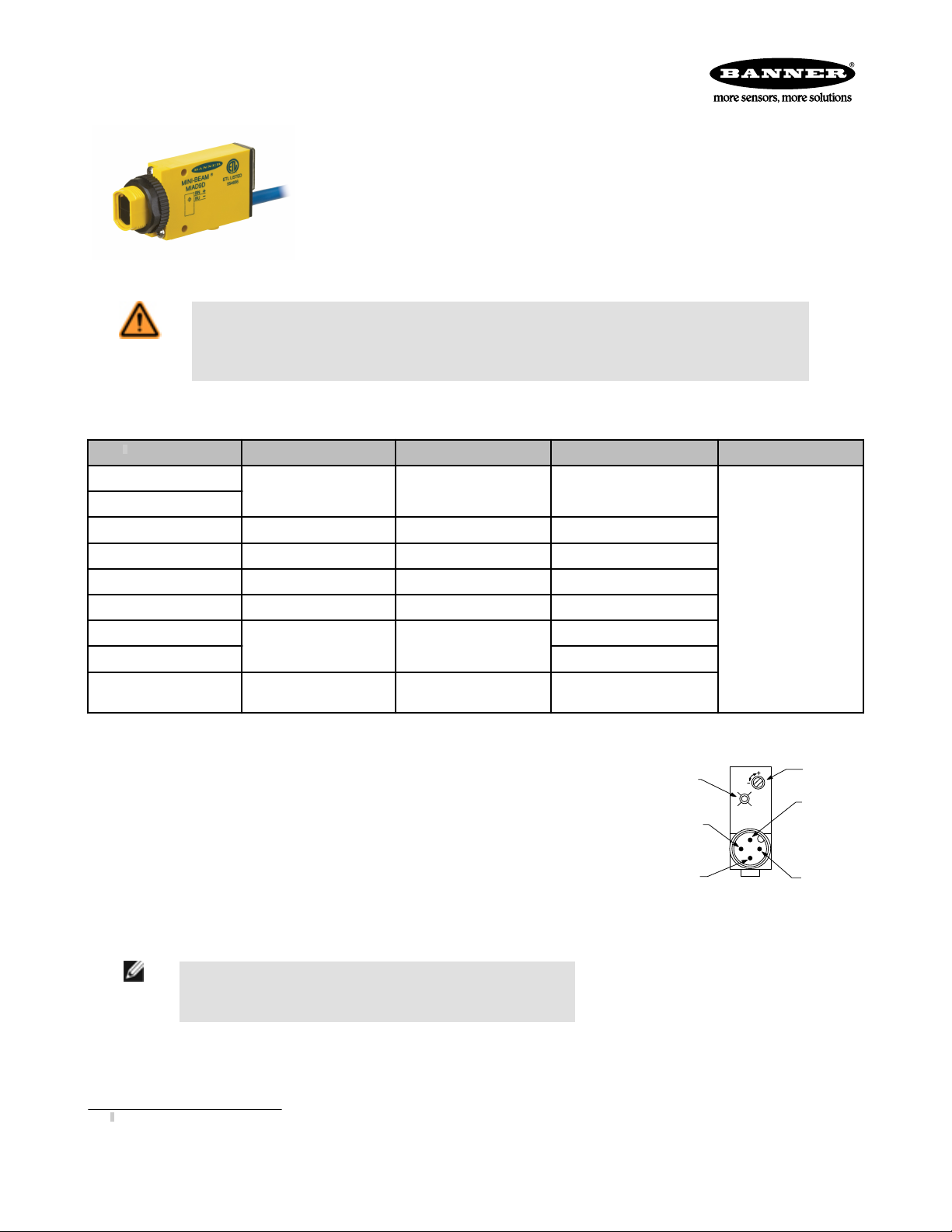
MINI-BEAM® MIAD9 Series
NAMUR Intrinsically Safe DC Sensors
• Intrinsically safe sensors with MINI-BEAM performance and small size
• For use with approved switching amplifiers with intrinsically safe input circuits
• Output 1 mA or less in the dark and 2 mA or more in the light
• Models with integral cable or quick-disconnect
WARNING: Not To Be Used for Personnel Protection
Never use this device as a sensing device for personnel protection. Doing so could lead to serious injury or death. This
device does not include the self-checking redundant circuitry necessary to allow its use in personnel safety applications. A sensor
failure or malfunction can cause either an energized or de-energized sensor output condition.
Models
1
Model
MI9E Emitter
MIAD9R Receiver
MIAD9LVAG Polarized Retroreflective Visible red, 650 nm 50 mm to 2 m (2 in to 7 ft)
MIAD9LV Retroreflective Visible red, 650 nm 5 m (16.4 ft)
MIAD9D Diffuse Infrared, 880 nm 380 mm (15 in)
MIAD9W Divergent Diffuse Infrared, 880 nm 75 mm (3 in)
MIAD9CV
MIAD9CV2 43 mm (1.7 in)
Fiber Optic (Glass) MIAD9F Infrared, 880 nm Range varies by sensing mode
Sensing Mode Sensing Beam Sensing Range Output Type
Opposed Infrared, 880 nm Range: 6 m (20 ft)
Constant Current
≤ 1.2 mA dark
≥ 2.1 mA light
16 mm (0.6 in)
Convergent Visible red, 650 nm
and fiber optics used
Overview
MIAD9 Series NAMUR Sensors are small, rugged, self-contained two-wire sensors designed for use with approved
switching amplifiers with intrinsically safe input circuits. MIAD9 Series sensors are designed in accordance with DIN 19
234.
These sensors vary the impedance across the sensor output, which passes 1 mA or less in the “dark” condition and 2
mA or more in the “light”condition. A red LED on the rear of the sensor lights whenever the sensor sees the “light”
condition. A rugged, clutched, 15-turn slotted brass screw Gain control potentiometer enables precise adjustment of
system sensitivity.
Models are available with either a 2 m (6.5 ft) or 10 m (30 ft) long attached PVC-covered cable, or a 4-pin Euro-style
quick disconnect (QD) connector. Quick disconnect models (with “Q” in the model number suffix) use MQD9-4.. mating
cable (either straight or right angle connector; see Quick-Disconnect (QD) Cables on page 7). Contact Banner Engineering for availability of sensor models with 10 m (30 ft) long attached cable.
NOTE: If sensors with output characteristics according to DIN 19 234 are used in
hazardous areas, they must be used with approved switching amplifiers with intrinsically safe input circuits.
Special Conditions for Safe Use
Parts of the enclosure are non-conducting and may generate an ignition-capable level of ESD. Cleaning of the equipment shall be done only with a damp cloth.
1
Only standard 2 m (6.5' ft cable models are listed. For 4-pin Euro-style Integral QD models: add suffix “Q” to the model number (for example, MIAD9RQ); accessory mating cable required, see Quick-Disconnect (QD) Cables on page 7.
Figure 1. Features (rear of sensor, quick-
disconnect model shown)
P/N 39616_web Rev. I 6/7/2013
Page 2

MINI-BEAM® MIAD9 Series
Hazardous Area Application
Associated apparatus may include amplifiers and barriers to monitor apparatus supply current, which is the apparatus output signal. Associated apparatus must limit both
supply voltage and supply current in the event of failures.
Installation Notes
Hazardous Area Application
Entity Parameters: Associated Apparatus may include amplifiers and barriers to monitor apparatus supply current, which is the apparatus output signal. Associated apparatus must limit both supply voltage and supply current in the event of failures.
CAUTION: Special Conditions for Safe Use: Parts of the Enclosure are non-conducting and may generate an ignition- capable level
of ESD. Cleaning of the equipment shall be done only with a damp cloth.
Associated Apparatus Sensor Apparatus
Voc ≤ 15V dc
Isc ≤ 60 mA
Ca ≥ C(cable) + Ci
Cable Parameters (if unknown)
C(cable) = 60 pF/ft.
L(cable) = 0.2 μH/ft.
Vmax = 15V dc
Imax = 60 mA
Ci = 0.3 μF
Li = 0
Pi = 225 mW
La ≥ L(cable) + Li
FM Installation
1. Associated Apparatus (barrier) entity parameters must meet the following requirements:
Voc ≤ Vmax
Isc ≤ Imax
Ca ≥ Ci + Ccable
La ≥ Li + Lcable
2. The Associated Apparatus shall not be connected to any device that uses or generates in excess of 250 Volts rms or dc.
3. Intrinsic safety ground, if required for the Associated Apparatus, shall be less than 1 ohm.
4. Installation shall be in accordance with the National Electrical Code (ANSI/NFPA70), local codes, Associated Apparatus manufacturer’s installation requirements and
ANSI/ISA RP12.6 for hazardous (classified) location installation.
5. Associated Apparatus is not required for installation of the devices within a Division 2 hazardous (classified) location. The maximum voltage for Division 2 installation
is 15V dc.
6. Maximum connector torque: 6 ft-lbs.
CSA Installation
1. Associated Apparatus (barrier) entity parameters must meet the following requirements:
Voc ≤ Vmax
Isc ≤ Imax
Ca ≥ Ci + Ccable
La ≥ Li + Lcable
2. The Associated Apparatus shall not be connected to any device that uses or generates in excess of 250 Volts rms or dc.
3. Intrinsic safety ground, if required for the Associated Apparatus, shall be less than 1 ohm.
4. Installation shall be in accordance with the Canadian Electrical Code, Part 1.
5. Associated Apparatus (barrier) shall be installed in accordance with the manufacturer’s instructions.
6. Associated Apparatus is not required for installation of the devices within a Division 2 hazardous (classified) location when installed in, or through the wall of a
suitable enclosure with provision for connection of rigid metal conduit per the Canadian Electrical Code, as acceptable to the local inspection authority having juris-
diction. The maximum rating for Division 2 installation is 15V dc, 60 mA.
7. In Division 2 installations, observe the following warning.
2 www.bannerengineering.com - tel: 763-544-3164 P/N 39616_web Rev. I
Page 3
MINI-BEAM
® MIAD9 Series
Specifications
WARNING: Explosion Hazard
Do not disconnect equipment unless power has been switched Off or the area is known to be non-hazardous.
Supply Voltage and Current
5 to 15V dc (provided by the amplifier to which the sensor is connected)
Output
Constant current output: ≤ 1.2 mA in the “dark” condition and ≥ 2.1 mA
in the “light” condition
Output Response Time
Opposed mode: 2 ms ON/400 μs OFF
All other modes: 5 ms ON/OFF (does not include amplifier response)
Adjustments
15-turn slotted brass screw GAIN (sensitivity) adjustment potentiometer
(clutched at both ends of travel); located on rear panel and protected by
a clear gasketed acrylic cover
Indicators
Red LED Alignment Indicator Device (AID) located on rear panel lights
when the sensor sees a “light” condition; pulse rate is proportional to
signal strength (the stronger the signal, the faster the pulse rate).
Construction
Reinforced thermoplastic polyester housing, totally encapsulated, o-ring
sealing, acrylic lenses, and stainless steel screws
Environmental Rating
Banner tested to NEMA standards 1, 2, 3, 3S, 4, 4X, 6, 12 and 13
IEC IP67
Connections
PVC-jacketed 2-conductor 2 m or 9 m cables, or special 4-pin Eurostyle quick-disconnect (QD) fitting are available; QD cables are ordered
separately.
Operating Conditions
Temperature: −40 °C to +70 °C (−40 °F to +158 °F)
Design Standards
ATEX (European)
EN 60079-0, EN 60079-11, and EN 60079-26
Canadian
CAN/CSA C22.2, No. 142-M1987, No.157-92, No. 1010.1, E60079-0,
and E60079-11
United States
FM Class 3600, 3610, and 3810, ANSI/ISA 61010-1 (82.02.01),
ANSI/ISA 60079-0, 60079-11, and 60079-26
Approvals
ATEX (European)
II 1 G Ex ia IIC T5 Ga Ta = –40 °C to 70 °C - 39616; Entity;
FM12ATEX0094X
Entity Parameters:
V
= 15 V dc, I
Max
= 60 mA, Ci = 0.3 μF, Li = 0 mH.
Max
Canada
Intrinsically safe for Class I, II and III, Division 1, Groups A, B, C, D, E, F
and G T5 Ta = –40 °C to 70 °C - 39616; Entity
Non-incendive for Class I, Division 2, Groups A, B, C and D, T5 Ta = –40
°C to 70 °C
Intrinsically safe for Class I, Zone 0 Ex ia Group IIC T5 Ta = -40°C to
70°C - 39616; Entity
Entity Parameters:
V
= 15 V dc, I
Max
= 60 mA, Ci = 0.3 μF, Li = 0 mH.
Max
a = Sensing mode D, W, F, LV, LVAG, CV, CV2 or R.
b = Connection method Q or blank.
United States
Intrinsically safe for Class I, II and III, Division 1, Groups A, B, C, D, E, F
and G T5 Ta = –40 °C to 70 °C - 39616; Entity
Non-incendive for Class I, Division 2, Groups A, B, C and D, T5 Ta = –40
°C to 70 °C
Suitable for Class II and III, Division 2 (Class II and III, Division 2 applies
only to model numbers ending in suffix "Q"), Groups F and G*, T5 Ta = –
40 °C to 70 °C
Intrinsically safe for Class I, Zone 0 AEx ia Group IIC T5 Ga Ta = –40 °C
to 70 °C; Entity
Entity Parameters:
V
= 15 V dc, I
Max
= 60 mA, Ci = 0.3 μF, Li = 0 mH.
Max
a = Sensing mode D, W, F, LV, LVAG, CV, CV2 or R.
b = Connection method Q or blank.
Certifications
P/N 39616_web Rev. I www.bannerengineering.com - tel: 763-544-3164 3
Page 4
1
10
100
0.10 m
(0.33')
1.0 m
(3.3')
10 m
(33')
0.01 m
(0.033')
E
X
C
E
S
S
G
A
I
N
DISTANCE
1000
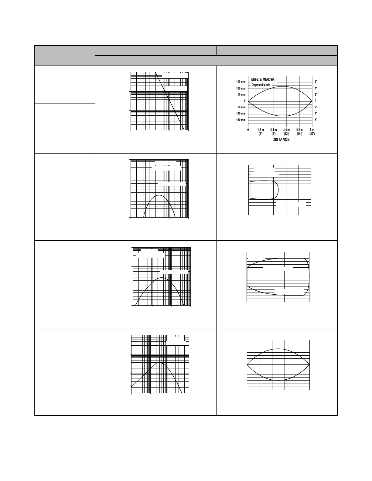
MI9E & MIAD9R
Opposed Mode
1
10
100
0.10 m
(0.33')
1.0 m
(3.3')
10 m
(33')
0.01 m
(0.033')
E
X
C
E
S
S
G
A
I
N
DISTANCE
1000
MIAD9LVAG
Retroreflective Mode
With BRT-3 Reflector
5 m
(15')
4 m
(12')
3 m
(9')
2 m
(6')
1 m
(3')
0
0
25 mm
50 mm
75 mm
25 mm
50 mm
75 mm
0
1.0"
2.0"
3.0"
1.0"
2.0"
3.0"
DISTANCE
MIAD9LVAG
Retroreflective Mode
With BRT-3 Reflector
1
10
100
0.10 m
(0.33')
1.0 m
(3.3')
10 m
(33')
0.01 m
(0.033')
E
X
C
E
S
S
G
A
I
N
DISTANCE
1000
MIAD9LV
Retroreflective Mode
With BRT-3 Reflector
5 m
(15')
4 m
(12')
3 m
(9')
2 m
(6')
1 m
(3')
0
0
25 mm
50 mm
75 mm
25 mm
50 mm
75 mm
0
1.0"
2.0"
3.0"
1.0"
2.0"
3.0"
DISTANCE
MIAD9LV
Retroreflective Mode
With BRT-3 Reflector
1
10
100
10 mm
(0.4")
100 mm
(4")
1000 mm
(40")
1 mm
(0.04")
1000
E
X
C
E
S
S
G
A
I
N
DISTANCE
MIAD9D
Diffuse Mode
375 mm
(15")
300 mm
(12")
225 mm
(9")
150 mm
(6")
75 mm
(3")
0
0
5 mm
10mm
15 mm
5 mm
10 mm
15 mm
0
0.2"
0.4"
0.6"
0.2"
0.4"
0.6"
DISTANCE
MIAD9D
Diffuse Mode
Performance Curves
Model Excess Gain Beam Pattern
Diffuse mode performance based on 90% reflectance white test card
MI9E Emitter
MIAD9R Receiver
MINI-BEAM® MIAD9 Series
MIAD9LVAG
MIAD9LV
MIAD9D
4 www.bannerengineering.com - tel: 763-544-3164 P/N 39616_web Rev. I
Page 5

1
10
100
1 mm
(0.04")
10 mm
(0.4")
100 mm
(4")
0.01 mm
(0.004")
1000
E
X
C
E
S
S
G
A
I
N
DISTANCE
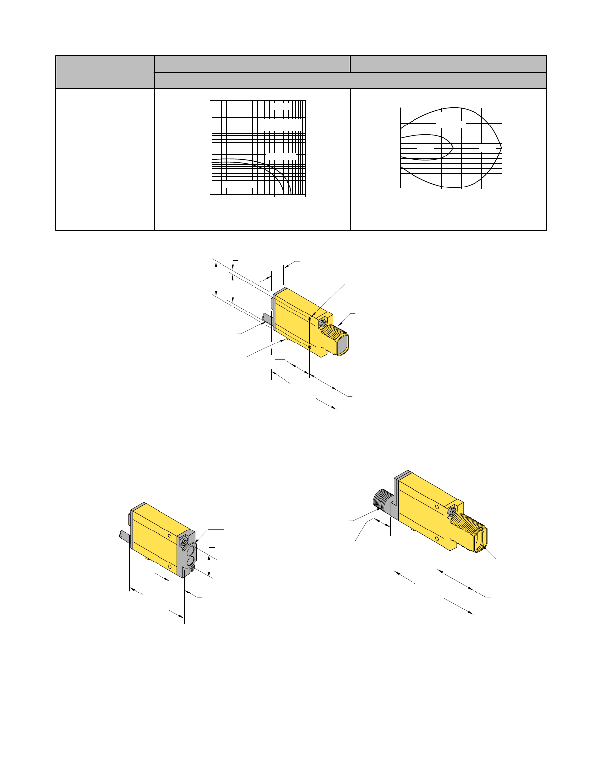
MIAD9W
Divergent
Diffuse Mode
125 mm
(5")
100 mm
(4")
75 mm
(3")
50 mm
(2")
25 mm
(1")
0
0
5 mm
10mm
15 mm
5 mm
10 mm
15 mm
0
0.2"
0.4"
0.6"
0.2"
0.4"
0.6"
DISTANCE
MIAD9W
Divergent Mode
1
10
100
1 mm
(0.04")
10 mm
(0.4")
100 mm
(4")
0.1 mm
(0.004")
1000
E
X
C
E
S
S
G
A
I
N
DISTANCE
MIAD9CV
Convergent Mode
1
10
100
1 mm
(0.04")
10 mm
(0.4")
100 mm
(4")
0.1 mm
(0.004")
1000
E
X
C
E
S
S
G
A
I
N
DISTANCE
MIAD9CV
Convergent Mode
1
10
100
10 mm
(0.4")
100 mm
(4")
1000 mm
(40")
1 mm
(0.04")
1000
E
X
C
E
S
S
G
A
I
N
DISTANCE
MIAD9CV2
Convergent Mode
125 mm
(5")
100 mm
(4")
75 mm
(3")
50 mm
(2")
25 mm
(1")
0
0
1 mm
2 mm
3 mm
1 mm
2 mm
3 mm
0
0.04"
0.08"
1.2"
0.04"
0.08"
1.2"
DISTANCE
MIAD9CV2
Convergent Mode
1
10
100
10 mm
(0.40")
100 mm
(4.0")
1000 mm
(40")
1 mm
(0.04")
1000
E
X
C
E
S
S
G
A
I
N
DISTANCE
MIAD9F
Opposed Mode
Glass Fibers
IT13S Fiber
IT23S Fiber
500 mm
(20")
400 mm
(16")
300 mm
(12")
200 mm
(8")
100 mm
(4")
0
0
25 mm
50 mm
75 mm
25 mm
50 mm
75 mm
0
1"
2"
3"
1"
2"
3"
DISTANCE
MIAD9F
Opposed Mode
IT13S IT23S
MINI-BEAM® MIAD9 Series
Model Excess Gain Beam Pattern
Diffuse mode performance based on 90% reflectance white test card
MIAD9W
MIAD9CV
MIAD9CV2
MIAD9F—Opposed Mode
P/N 39616_web Rev. I www.bannerengineering.com - tel: 763-544-3164 5
Page 6
1
10
100
1 mm
(0.04")
10 mm
(0.40")
100 mm
(4")
0.1 mm
(0.004")
1000
E
X
C
E
S
S
G
A
I
N
DISTANCE
MIAD9F
Diffuse Mode
Glass Fibers
BT23S Fiber
BT13S Fiber
37.5 mm
(1.5")
30 mm
(1.2")
22.5 mm
(0.9")
15 mm
(0.6")
7.5 mm
(0.3")
0
0
.06 mm
1.2 mm
1.8 mm
.06 mm
1.2 mm
1.8 mm
0
.025"
.050"
.075"
.025"
.050"
.075"
DISTANCE
MIAD9F
Diffuse Mode
BT13S BT23S
66.0 mm
(2.60")
12.2 mm (0.48")
Mounting Peg
(ø 6.3 mm x 2.5 mm)
ø 3 mm Clearance (2)
M18 x 1 x 15 mm Thread
(Mounting Nut Supplied)
3.2 mm
(0.13")
27.4 mm (1.08")
30.7 mm
(1.21")
24.1 mm
(0.95")
19.1 mm
(0.75")
2 m (6.5') Cable
51.8 mm
(2.04")
13.2 mm
(0.52")
18.0 mm
(0.71")
Bezel
Fiber Optic Fitting
69.9 mm
(2.75")
M12 x 1 Thread
Quick-disconnect
31.2 mm (1.23")
18.5 mm
(0.73")
Model Excess Gain Beam Pattern
Diffuse mode performance based on 90% reflectance white test card
MIAD9F—Diffuse Mode
Dimensions
MINI-BEAM® MIAD9 Series
Figure 2. Opposed, Retro, Diffuse, Convergent Models (Suffix E, R, LV, D, and CV)
6 www.bannerengineering.com - tel: 763-544-3164 P/N 39616_web Rev. I
Figure 3. Diffuse Models (suffix W)
Figure 4. Glass Fiber Models (suffix F)
Page 7
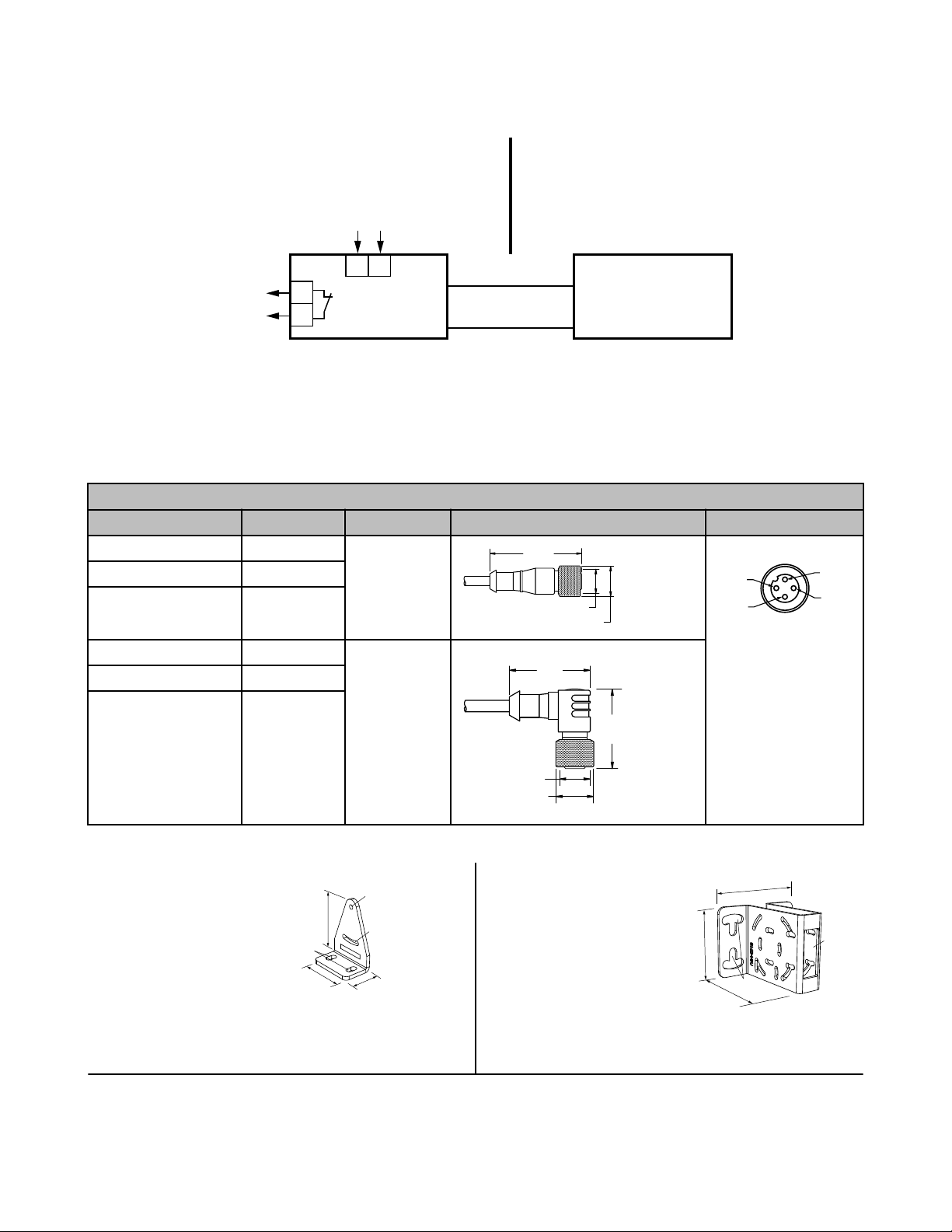
MIAD9 Series
NAMUR Sensor
DIN 19234
Brown
Non-Hazard Area Hazard Area
Blue
+
+
Switching Amplifier
(sensor power source
and monitor)
Switched
Output
Factory Mutual Approved
Associated Apparatus
Apparatus
–
–
V dc Supply
44 Typ.
ø 14.5
M12 x 1
2
3
4
1
32 Typ.
[1.26"]
30 Typ.
[1.18"]
ø 14.5 [0.57"]
M12 x 1
46
B
C
A
32
20
70
54
65
16
A
B
MINI-BEAM® MIAD9 Series
Hookups
Accessories
Quick-Disconnect (QD) Cables
4-Pin Threaded M12/Euro-Style Cordsets (for use with NAMUR sensors)
Model Length Style Dimensions Pinout
MQD9-406 1.83 m (6 ft) Straight
MQD9-415 4.57 m (15 ft)
MQD9-430 9.14 m (30 ft)
MQD9-406RA 1.83 m (6 ft) Right-Angle
MQD9-415RA 4.57 m (15 ft)
MQD9-430RA 9.14 m (30 ft)
1 = Brown
2 = Blue
Brackets
SMB312S
• Stainless steel 2-axis, side-mount
bracket
SMB46U
• Right-angle
• U bracket for sensor protection
• 14-ga. 316 stainless steel
A = 4.3 x 7.5, B = diam. 3, C = 3 x
15.3
P/N 39616_web Rev. I www.bannerengineering.com - tel: 763-544-3164 7
Hole center spacing: A = 16.0
Hole size: A = 16.5 x 18.7, B = 34.0 x 13.0
Page 8

51
24
23
B
C
A
30
41
46
A
B
C
46
41
B
C
A
32
66
69
A
B
65
54
27
A
41
46
A
B
30
C
54
43
65
16
A
B
B
A
51
42
25
MINI-BEAM® MIAD9 Series
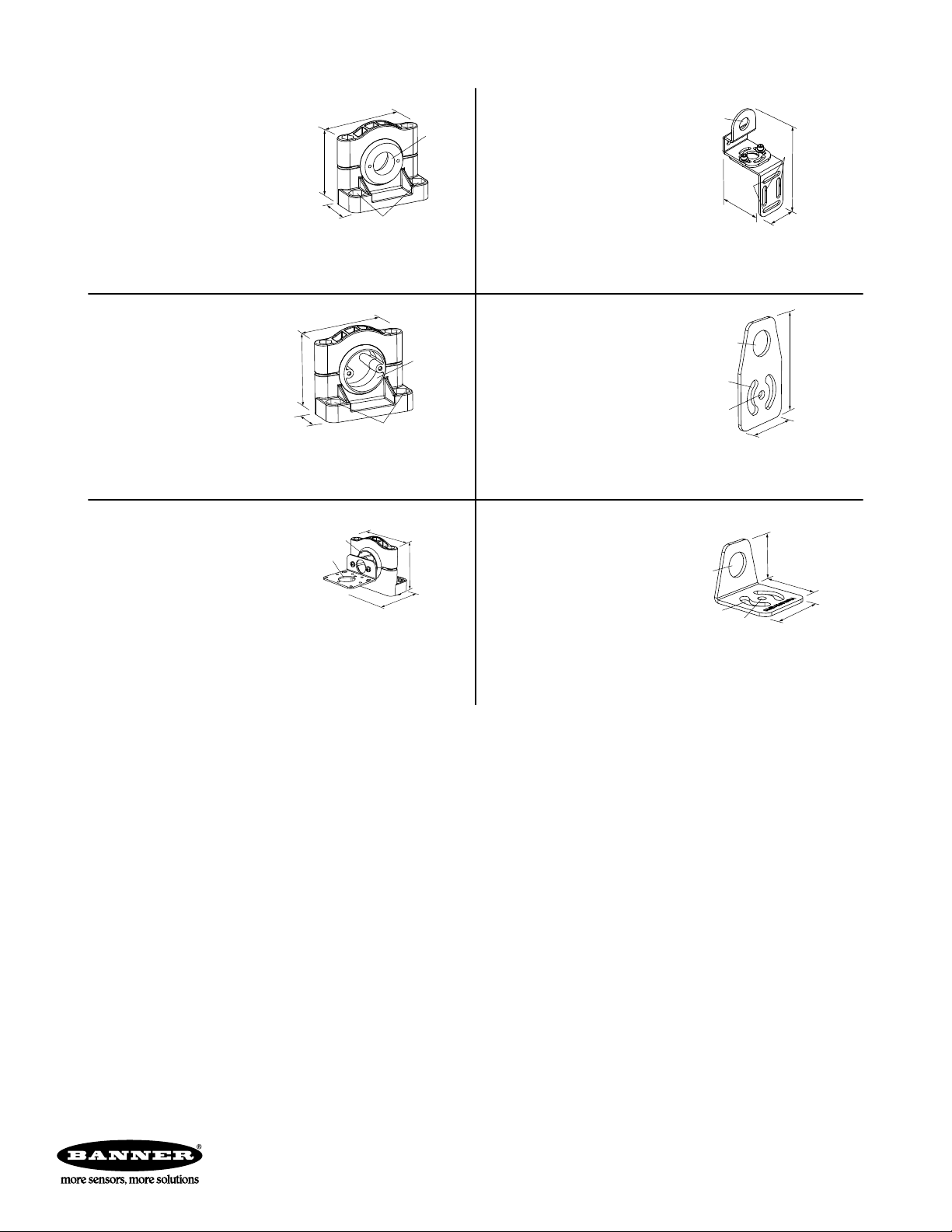
SMB312B
• Stainless steel 2-axis, bottommount bracket
• Includes mounting foot
A = diam. 6.9, B = 4.3 x 10.5, C = 3.1
x 15.2
SMB312PD
• Right-angle mounting bracket with
a curved slot for versatile orientation
• 12-ga. stainless steel
• 18 mm sensor mounting hole
• Clearance for M4 (#8) hardware
Hole center spacing: A to B = 24.2
Hole size: A = ø 4.6, B = 17 × 4.6, C = ø 18.5
NOTE: Not for use with plastic fiber optic
sensors
SMB18A
• Right-angle mounting bracket with
a curved slot for versatile orientation
• 12-ga. stainless steel
• 18 mm sensor mounting hole
• Clearance for M4 (#8) hardware
Hole center spacing: A to B = 24.2
Hole size: A = ø 4.6, B = 17.0 × 4.6, C = ø 18.5
SMB18FA..
• Swivel bracket with tilt and pan movement for precision adjustment
• Easy sensor mounting to extruded rail
T-slots
• Metric and inch size bolts available
• 18 mm sensor mounting hole
Hole size: B=ø 18.1
Model Bolt Thread (A)
SMB18FA 3/8 - 16 × 2 in
SMB18FAM10 M10 - 1.5 × 50
SMB46L
• Right-angle
• L bracket
• 14-ga. 316 stainless steel
Hole center spacing: A = 16.0
Hole size: A = 16.5 x 18.7
SMB46S
• Right-angle
• S bracket
• 14-ga. 316 stainless steel
Hole center spacing: A = 16.0
Hole size: A = 16.5 x 18.7, B = 34.0 x 10.0
SMB18Q
• Right-angle flanged bracket
• 18 mm sensor mounting hole
• 12-ga. stainless steel
Hole center spacing: A to B = 24.2
Hole size: A = ø 4.6, B = 17.0 × 4.6, C = ø 19.0
SMB18SF
• 18 mm swivel bracket with M18 × 1
internal thread
• Black thermoplastic polyester
• Stainless steel swivel locking hardware included
Hole center spacing: A = 36.0
Hole size: A = ø 5.3, B = ø 18.0
8 www.bannerengineering.com - tel: 763-544-3164 P/N 39616_web Rev. I
Page 9
B
A
67
59
29
137
64
42
B
A
C
A
67
58
29
B
45
78
A
B
C
68
57
78
A
B
48
45
40
A
B
C
MINI-BEAM® MIAD9 Series
SMB3018SC
• 18 mm swivel side or barrelmount bracket
• Black reinforced thermoplastic
polyester
• Stainless steel swivel locking
hardware included
Hole center spacing: A = 50.8
Hole size: A = ø 7.0, B = ø 18.0
SMB30SUS
• Side-mount swivel with extended
range of motion
• Black reinforced thermoplastic
polyester
• Stainless steel swivel locking
hardware included
Hole center spacing: A = 50.8, B = 24.1
Hole size: A = ø 7, B = ø 7.6
SMB30SK
• Flat-mount swivel bracket with extended range of motion
• Black reinforced thermoplastic
polyester and 316 stainless steel
• Stainless steel swivel locking
hardware included
Hole center spacing: A = 50.8
Hole size: A = ø 7, B = ø 18
SMB18UR
• 2-piece universal swivel bracket
• 300 series stainless steel
• Stainless steel swivel locking
hardware included
• Mounting hole for 18 mm sensor
Hole center spacing: A = 25.4, B = 46.7
Hole size: B = 6.9 × 32.0, C = ø 18.3
SMBAMS18P
• Flat SMBAMS series bracket with
18 mm hole for mounting sensors
• Articulation slots for 90+° rotation
• 12-ga. (2.6 mm) cold-rolled steel
Hole center spacing: A = 26.0, A to B = 13.0
Hole size: A = 26.8 × 7.0, B = ø 6.5, C = ø 19.0
SMBAMS18RA
• Right-angle SMBAMS series
bracket with 18 mm hole for
mounting sensors
• Articulation slots for 90+° rotation
• 12-ga. (2.6 mm) cold-rolled steel
Hole center spacing: A = 26.0, A to B = 13.0
Hole size: A = 26.8 × 7.0, B = ø 6.5, C = ø 19.0
Banner Engineering Corp Limited Warranty
Banner Engineering Corp. warrants its products to be free from defects in material and workmanship for one year following the date of shipment. Banner Engineering Corp.
will repair or replace, free of charge, any product of its manufacture which, at the time it is returned to the factory, is found to have been defective during the warranty
period. This warranty does not cover damage or liability for misuse, abuse, or the improper application or installation of the Banner product.
THIS LIMITED WARRANTY IS EXCLUSIVE AND IN LIEU OF ALL OTHER WARRANTIES WHETHER EXPRESS OR IMPLIED (INCLUDING, WITHOUT LIMITATION,
ANY WARRANTY OF MERCHANTABILITY OR FITNESS FOR A PARTICULAR PURPOSE), AND WHETHER ARISING UNDER COURSE OF PERFORMANCE,
COURSE OF DEALING OR TRADE USAGE.
This Warranty is exclusive and limited to repair or, at the discretion of Banner Engineering Corp., replacement. IN NO EVENT SHALL BANNER ENGINEERING CORP. BE
LIABLE TO BUYER OR ANY OTHER PERSON OR ENTITY FOR ANY EXTRA COSTS, EXPENSES, LOSSES, LOSS OF PROFITS, OR ANY INCIDENTAL, CONSEQUENTIAL OR SPECIAL DAMAGES RESULTING FROM ANY PRODUCT DEFECT OR FROM THE USE OR INABILITY TO USE THE PRODUCT, WHETHER ARISING IN CONTRACT OR WARRANTY, STATUTE, TORT, STRICT LIABILITY, NEGLIGENCE, OR OTHERWISE.
Banner Engineering Corp. reserves the right to change, modify or improve the design of the product without assuming any obligations or liabilities relating to any product
previously manufactured by Banner Engineering Corp.
www.bannerengineering.com - tel: 763-544-3164
 Loading...