

Page 1
SME312D
Printed in USA 06/01 P/N 65161
Diffuse mode sensors with automatic sensitivity adjustment
Reflexionslichttaster mit automatischer Empfindlichkeitseinstellung
Détecteurs diffus à réglage automatique de la sensibilité
ティーチモード対応 拡散反射型光電センサ
MINI-BEAM Expert ™ SME312D..., SME312W...
Banner Engineering Belgium bvba
Phone: +32-2-456 07 80
Fax: +32-2-456 07 89
E-mail: mail@bannerengineering.be
SME312W
Connections Anschluss
1 Bn brown braun
2 Wh white weiß
3 Bu blue blau bleu
blanc
brun
Raccordement
4 Bk black schwarz noir
5 Gy
grey
*external
programming
grau
*externe
Programmierleitung
gris
*câble de
programmation
externe
**load **Last **charge
Packing List Lieferumfang Livraison
Sensor Sensor Détecteur
Data Sheet (English) Datenblatt (Englisch) Notice technique (anglais)
Installation Sheet (multilingual) Beipackzettel (mehrsprachig)
Notice d’installation
(multilingue)
M18 Nut (...D models only) Mutter M18 (nur für Typ ...D) Ecrous M18 (seulement typ ...D)
SME312D(W)...QD
Max. range • max. Reichweite
Portée max. •
検出距離
Description
SME312W 130 mm infrared, 2 m cable
SME312WQD 130 mm infrared, connector*
SME312D 380 mm infrared, 2 m cable
SME312DQD 380 mm infrared, connector* infarot, Steckverbinder*
infrarot, 2-m-Kabel
infrarot, Steckverbinder*
infrarot, 2-m-Kabel
Beschreibung
infrarouge, 2 m câble
infrarouge, connecteur*
infrarouge, 2 m câble
infrarouge, connecteur*
Description
SME312...QD
* eurocon connector, eurocon-Steckverbinder, connecteur eurocon,
ユーロスタイルコネクタ
M18ナット
同梱品リスト
センサ
データシート(英語)
取扱説明書(4カ国語)
青
白
茶
配線
黒
灰
*
外部設定入力
**
負荷
説明
赤外光、コネクタ
*
赤外光、コネクタ
*
赤外光、2mケーブル
赤外光、2mケーブル
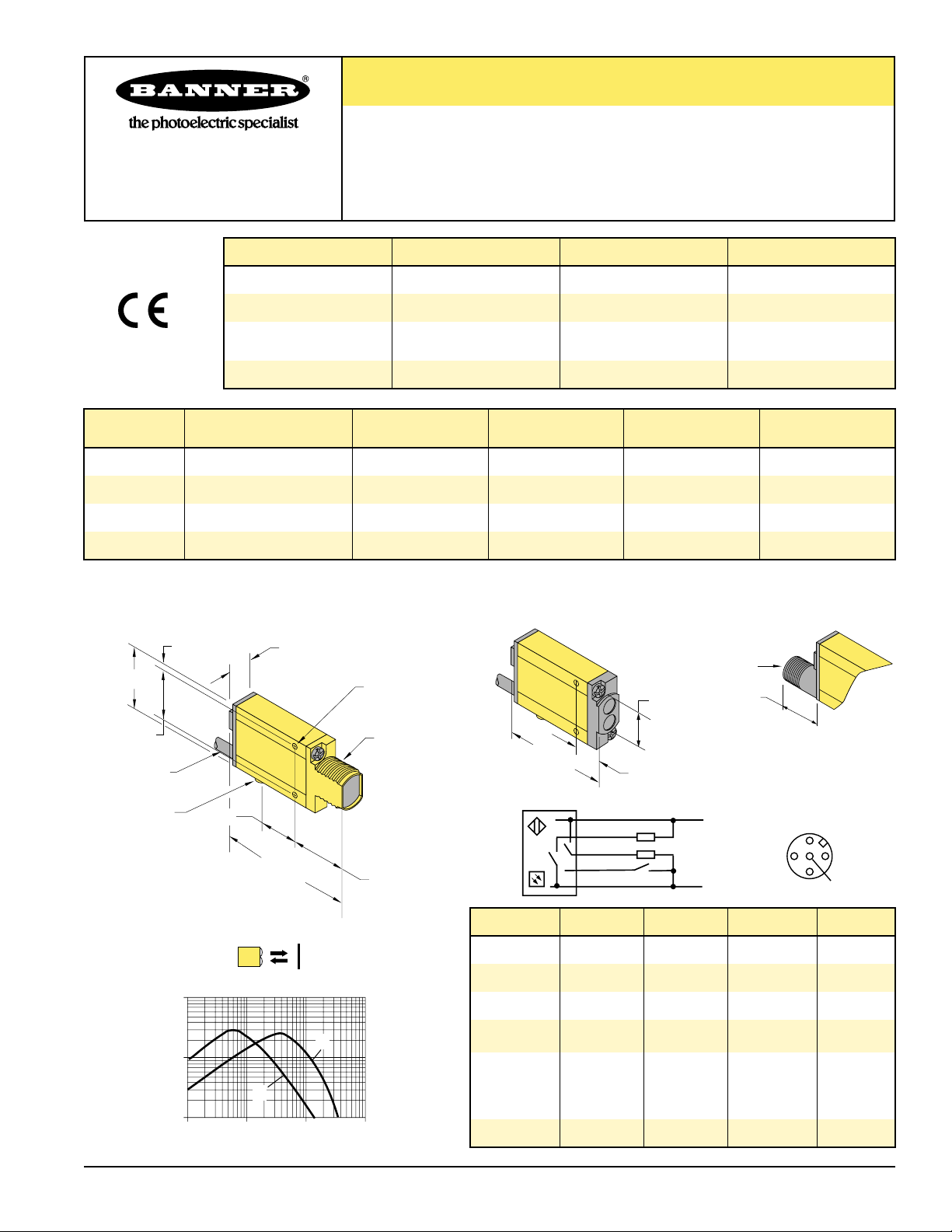
30,7 mm
3,2 mm
12,2 mm
ø 3 mm (2)
M12 x 1
18 mm
20 mm
24,1 mm
2 m
ø 6,3 mm x 2,5 mm
E
X
C
E
S
S
G
A
I
N
19,1 mm
66 mm
100
D
10
W
1
1 10 100 1000 mm
M18 x 1 x 15 mm
27,4 mm
51,8 mm
1 Bn
2 Wh
4 Bk
5 Gy *
3 Bu
13,2 mm
+
**
**
–
2
3
1
5
4
Page 2
2
a Push button Drucktaster Bouton-poussoir
b Green/red LED grüne/rote LED LED verte/rouge
c Yellow LED gelbe LED LED jaune
d
Cable or
eurocon
connector
Kabel oder
euroconSteckverbinder
Câble ou
connecteur
eurocon
Indicator LEDs in RUN mode
Green LED ON: Power OK
Green LED Flashing: Signal strength close to
switching threshold
Yellow LED ON: Outputs conducting
Yellow LED OFF: Outputs not conducting
AID™ (Alignment Indication Device)
In teach mode, the bicolor indication LED
flashes red at a rate proportional to the received
signal strength. This indicates the best optical
alignment.
Remote programming
The grey teach-wire (connector pin 5) permits
teaching the sensor the light and dark
conditions using a remote switch or a PLC.
Connecting it to DC common (–) has the same
effect as pushing the teach button. Pulses and
the intervals between them must be between 40
and 800 ms long.
Disabling the teach button
The teach button can be disabled (locked) or
enabled (unlocked) by pulsing the remote teachwire 4 times. Pulses and the intervals between
them must be between 40 and 800 ms long.
Troubleshooting
If an internal memory error occurs, the power
LED will flash alternating red/green. If this
occurs, either cycle the power or reteach the
sensor.
Sensing range/Excess gain
The range at which an object can be detected
will depend on the surface of the target. The
specified range is valid for a specific test card.
The table gives estimates for the required
excess gain factor to detect various surfaces in
clean laboratory conditions.
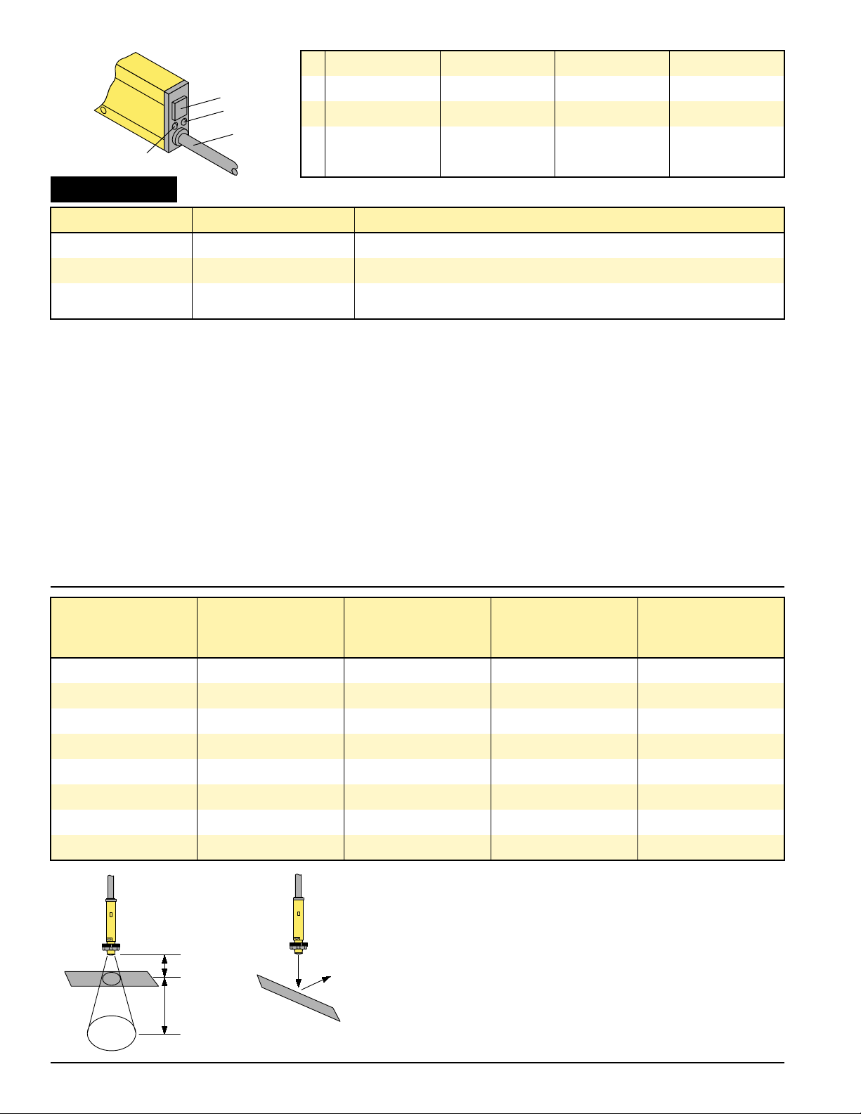
Shiny surfaces
Very shiny surfaces will reflect all the emitted
light away from the sensor if it is not positioned
exactly perpendicular to the surface. Sensors
with a diverging beam, like the SME312W, will
also detect skewed or fluttering surfaces.
Background
For an application to work reliably, objects or
surfaces that reflect an equal amount of light as
the target to be detected should be at least 4
times as far away from the sensor as the actual
target.
Status Action Result
RUN mode (green LED ON) Push and hold button for > 2 s Green LED goes OFF, yellow LED comes ON, red LED flashes (see AID™)
Teach condition 1 Present ON condition; click once Green LED stays OFF, yellow LED goes OFF, red LED flashes (see AID™)
Teach condition 2 Present OFF condition; click once
If contrast is acceptable: green LED comes ON, sensor goes into RUN mode
If contrast is too low: yellow LED comes ON, sensor goes back to teach condition 1
Setting the configuration:
ENGLISH
Surface to be sensed zu detektierende Oberfläche
Test card Testkarte
White printing paper weißes Druckerpapier
Clean pine wood sauberes Pinienholz Bois de pin claire
Papier blanc
Carte de test
Surface à détecter
きれいな松の板
白色のプリント用紙
テストカード
Cardboard Pappe Carton
ダンボール
Rough wooden pallet grobe Holzpalette Palette en bois
表面の粗い木製パレット
Black plastic schwarzer Kunsstoff Plastique noir
黒色プラスチック
Rubber tires Gummireifen Pneu de voiture
タイヤ
Stainless steel Edelstahl Acier inoxydable
ステンレス
0,2*
60
6
5
1,3
1,2
1,1
1
Min. required excess gain
Min.Funktionsreserve
Gain de fonction min. requis
必要エクセスゲイン
* Only when the sensor is exactly perpendicular to the surface.
* Nur bei exakter senkrechter Ausrichtung des Sensors zur Oberfläche.
* Seulement quand le détecteur est exactement perpendiculaire à la surface.
*
ターゲットとセンサが直角な場合
x
> 3x
shiny surface
glänzende Oberfläche
surface brillante
光沢面
Most light is lost to specular reflection with shiny surface at an angle to sensor lens.
Die Lichtintensität wird aufgrund spiegelnder Reflexion durch glänzende Oberflächen,
die winklig zur Sensorlinse ausgerichtet sind, deutlich gemindert.
La plupart de la lumière est réflechie en dehors du champs de vue du détecteur du à
l’angle de la surface brillante.
光沢面で斜角を持たせて反射させた場合、光線の大半は鏡面反射してしまいます。
ターゲット表面
黄色LED
ケーブル、または
ユーロスタイル
QDコネクタ
プッシュボタン
緑色/赤色LED
TEACH
c
a
b
d
Page 3

3
Visualisation par LED en mode RUN
LED Verte Fixe: Tension de service OK
LED Verte Clignotante: Le signal reçu est
proche du signal de commutation
LED Jaune ON: Sorties activées
LED Jaune OFF: Sorties désactivées
AID™ (Aide au réglage)
En mode apprentissage, la LED bicolore rouge
clignote proportionnellement à l’intensité du
signal reçu. Ceci indique si l’alignement est
optimal.
Programmation à distance
Le fil gris (broche 5 pour la version à
connecteur) permet la programmation du
détecteur par un bouton poussoir externe ou
un API. Connectez le fil gris au commun (–),
ainsi vous accèdez aux même fonctions qu’en
utilisant le bouton d’apprentissage. Les
impulsions et les intervalles doivent durer de
40 à 800 ms.
Désactivation du bouton d’apprentissage
Le bouton d’apprentissage peut être désactivé
et activé en effectuant 4 impulsions avec le fil
gris. Les impulsions et les intervalles doivent
durer de 40 à 800 ms.
Dépannage
Si une erreur de mémoire interne se produit
alors la LED de tension de service clignotera
alternativement rouge/vert. Si cela se produit,
retirez la tension de service ou refaites la
procédure d’apprentissage du détecteur.
Distance de détection/gain
La distance à laquelle un objet peut être
détecté dépend de la surface de la cible. La
distance de détection est spécifiée par rapport
à une carte de test spécifique. Le tableau
donne le facteur de gain exigé pour détecter
différentes surfaces dans un laboratoire
propre.
Surfaces brillantes
Les surfaces réfléchissantes doivent être
positionnées perpendiculairement à l’axe du
détecteur, sinon la lumière ne sera pas
renvoyée vers le détecteur. Les détecteurs
avec un faisceau divergent comme le
SME312W détectera les surfaces instables et
obliques.
Arrière-plan
Pour un fonctionnement fiable, les objets ou
surfaces renvoyant une même quantité de
lumière que la cible à détecter devront se
situer au moins 4 fois plus loin du détecteur
par rapport à la cible.
Etats Action Résultat
Mode RUN (LED verte ON) Appuyer pendant au moins 2 s LED verte s’éteint, LED jaune s’allume, LED rouge clignote (voir AID™)
Apprentissage condition 1 Présenter condition 1, appuyez 1 fois LED verte reste éteinte, LED jaune s’éteint, LED rouge clignote (voir AID™)
Apprentissage condition 2 Présenter condition 2, appuyez 1 fois
Si le contraste est acceptable: LED verte s’allume, détecteur va en mode RUN
Si le contraste est trop faible: LED jaune s’allume, détecteur retourne à la condition 1
LED-Anzeigen im RUN-Modus (im Betrieb)
grüne LED an: Betriebsspannung OK
grüne LED blinkt: Signalstärke nahe der
Schaltschwelle
gelbe LED an: Ausgang geschaltet
gelbe LED aus: Ausgang nicht geschaltet
AID™ Ausrichthilfe
(Alignment Indication Device). Im TeachModus blinkt die zweifarbige LED rot mit einer
Blinkfrequenz proportional zu der
empfangenen Lichtmenge. Somit kann eine
optimale optische Ausrichtung erreicht
werden.
Programmierung mittels Steuerleitung
Die Steuerleitung (graue Litze oder Anschluss
5 bei der Steckerversion) ermöglicht die
externe Programmierung z.B. über eine SPS.
Der Anschluss an das neg. Potential (–) ist
einem Knopfdruck auf den Teach-In-Knopf
gleichzusetzen, Impulsdauer/Impulsepausen
40...800 ms.
Programmierschutz
Der Teach-In-Knopf kann durch vier Impulse
über die Steuerleitung gesperrt werden.
Impulsdauer/Impulsepausen 40...800 ms.
Fehleranzeige
Abwechselndes Blinken der Zweifarben-LED
zur Anzeige der Betriebsspannung (grün/rot)
signalisiert einen internen Programmfehler. In
diesem Fall sollte die Betriebsspannung
kurzzeitig ab- und wieder angeschaltet oder
der Teach-Vorgang erneut durchgeführt
werden.
Reichweite/Funktionsreserve
Die Reichweite, mit der ein Objekt erfasst
werden kann, hängt von seiner Oberfläche ab.
Der genannte Bereich gilt für eine spezifizierte
Testkarte. Die Tabelle gibt annähernd an,
welcher Funktionsreservefaktor erforderlich
ist, um verschiedene Oberflächen unter
Laborbedingungen zu erfassen.
Glänzende Oberflächen
Stark reflektierende Oberflächen reflektieren
sämtliches Licht vom Sensor weg, wenn
dieser nicht genau vertikal zur Oberfläche
ausgerichtet ist. Winkellichttaster wie der
SME312W erkennen selbst gekippte oder
“flatternde” Oberflächen.
Hintergrund
Zur sicheren Erfassung des zu detektierenden
Objekts müssen angrenzende Oberflächen
oder Gegenstände, die die gleiche Lichtmenge
wie das zu erfassende Objekt reflektieren,
einen vierfach höheren Abstand zum Sensor
als das tatsächlich zu erfassende Objekt
aufweisen (s. Tabelle).
Status Aktion Resultat
RUN-Modus
(grüne LED an)
Programmierknopf > 2 s gedrückt halten grüne LED geht aus, gelbe LED leuchtet auf, rote LED blinkt (s. AID™)
Lernzustand 1
Erster Zustand (Ausgang geschaltet) wird dem Sensor
gezeigt und eingelernt, einfacher Knopfdruck
grüne LED ist aus, gelbe LED geht aus, rote LED blinkt (s. AID™)
Lernzustand 2
Zweiter Zustand (Ausgang frei) wird dem Sensor gezeigt
und eingelernt, einfacher Knopfdruck
Kontrast ist ausreichend: Sensor geht in den RUN-Modus über
Kontrast ist unzulänglich: Sensor geht zu Lernzustand 1 zurück
Réglage de la configuration:
FRANÇAIS
Konfiguration:
DEUTSCH
Page 4

Banner Engineering Corp., 9714 Tenth Ave. No., Minneapolis, MN 55441 • Phone: 763.544.3164 • E-mail: sensors@bannerengineering.com • www.bannerengineering.com
IMPORTANT SAFETY
WARNING!
The sensors described in this sheet do NOT include the self-checking redundant circuitry necessary to allow their use
in personnel safety applications. A sensor failure or malfunction can result in either an energised or de-energised
output condition. Never use these products as sensing devices for personnel safety.
ACHTUNG,
WICHTIGER WARNHINWEIS!
Die in diesem Beipackzettel beschriebenen Sensoren dürfen nicht für Personenschutz-Einrichtungen eingesetzt
werden. Sie verfügen weder über die dafür notwendigen redundanten Sicherheitskomponenten, noch liegen für sie
die notwendigen gesetzlich vorgeschriebenen Zulassungen vor.
ATTENTION!
Les détecteurs décrits dans le présent document ne disposent pas de dispositifs nécessaires pour pouvoir être
utilisés dans des applications de protection de personnes. Une panne du détecteur peut commuter ou non la sortie.
Ces appareils ne doivent jamais être utilisés comme détecteurs de protection de personnes.
Specifications Spezifikationen Caractéristiques
Supply voltage
Versorgungsspannung U
B
Tension d’alimentation 10...30 VDC
Supply ripple
Restwelligkeit W
SS
Taux d’ondulation
≤ 10 % U
e
No load current
Leerlaufstrom I
O
Consommation propre à vide < 45 mA
Output configuration Ausgangskonfiguration Configuration de la sortie 1 pnp + 1 npn
Output rating
(continuous load)
Bemessungsbetriebsstrom Courant de charge (continu) ≤ 150 mA
Output response Ansprechzeit Temps de réponse 500 µs ON/OFF
Delay at power-up
Bereitschaftsverzug t
v
Retard à la disponibilité 1 s (outputs OFF)
Housing material Gehäuse Boîtier PBT
Lens material Linse Lentille
acrylic – Acryl – acrylique
Protection Schutzart Indice de protection IP67
Temperature rating Umgebungstemperatur Gamme de température -20...+70 °C
アクリル
RUNモードでのLED表示
LED(緑)点灯:電源OK
LED(緑)点滅:受光量がしきい値に近い
LED(黄)点灯:出力ON
LED(黄)消灯:出力OFF
AIDTM(受光量表示)
ティーチモード時、受光量に応じて二色表示LED
が赤で点滅します。点滅周期が早いほど光軸が合
っていることを示します。
リモートプログラミング
灰色のワイヤ(コネクタピン 5)にスイッチやPLC
を接続し、明状態と暗状態を外部からセンサにテ
ィーチングできます。このワイヤをDC電源コモ
ン(−)に接続した場合、ティーチボタンを押す
のと同様の効果が得られます。パルス、およびパ
ルス間隔の許容値は40〜800msです。
ティーチボタン操作の禁止
ティーチ入力に4回パルスを加えると、ティーチ
ボタン操作の禁止(ロック状態)、または禁止解除
(ロック解除)が可能です。パルス、およびパルス
間隔の許容値は40〜800msです。
トラブルシューティング
内部メモリエラーが発生した場合、電源LEDは
赤/緑の交互点滅となります。この場合は、電源
を一旦切って入れなおすか、ティーチングし直し
て下さい。
検出範囲/エクセスゲイン(余裕度)
検出距離は、ターゲット表面により大きく異なり
ます。検出距離の仕様は、当社テストカードによ
るものです。クリーンな試験室環境で測定した場
合の、様々な表面における必要エクセスゲインを
下表に示します。
光沢面
ターゲット表面が鏡面状の場合、センサとターゲ
ットが垂直になっていないと、ビームがセンサと
違う方向に反射されてしまい検出できない場合が
あります。ターゲットに対して斜めになる場合や
バタツキがある場合は、広角拡散反射型の
SME312Wをご使用下さい。
背景
ターゲットと同量のビームを反射してしまう背
景がある場合、センサと背景の距離を検出距離
(センサとターゲットの距離)の4倍以上にして
下さい。
状態 操作 結果
RUNモード
(緑色LED点灯)
ボタンを2秒以上押す LED(緑)消灯、LED(黄)点灯、LED(赤)点滅(AID参照)
ティーチ1
出力ONの状態:1回クリック LED(緑)消灯、LED(黄)消灯、LED(赤)点滅(AID参照)
ティーチ2
出力OFFの状態:1回クリック
コントラストが良好な場合:LED(緑)点灯、センサはRUNモードに入る
コントラスト不足の場合 :LED(黄)点灯、センサはティーチ1の状態に戻る
感度調整
日本語
仕様
電源電圧
リップル
消費電流
出力構成
負荷電流
応答度
初期リセット時間
ケース材質
レンズ材質
保護構造
使用周囲温度範囲
注意!
この取扱説明書に記載のセンサは、人身保護用に使用可能な二重化された自己診断機能を内蔵していません。
センサの誤作動により出力がONする場合とOFFする場合のどちらもあります。
この製品を、人身保護用としては絶対に使用しないで下さい。
 Loading...