

Page 1
®
bn
bu
Load
24-240V ac
rd/bk
gn
rd/wh
Load
24-240V ac
bn
bu
24-240V ac
rd/bk
gn
rd/wh
24-240V ac
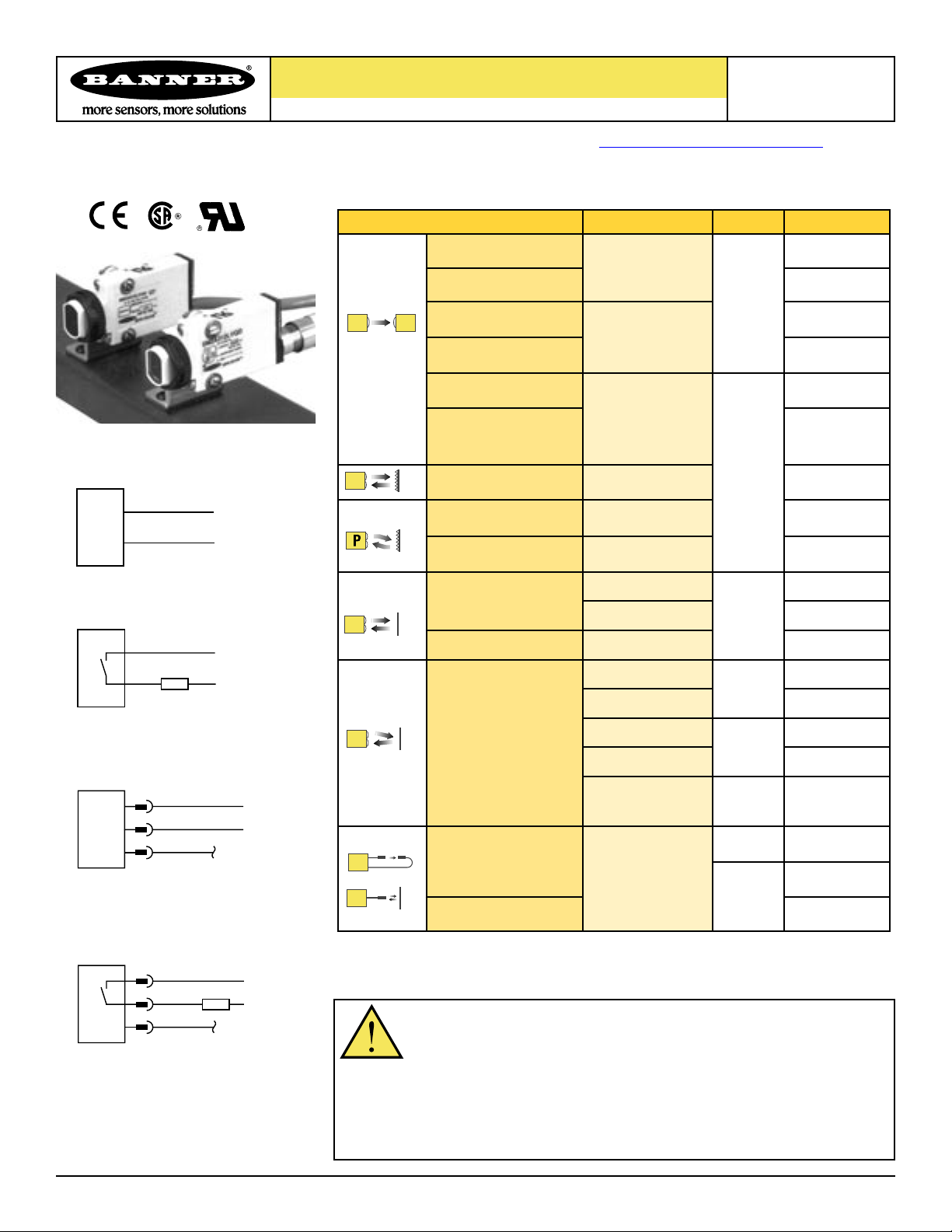
MINI-BEAM
ac-Voltage Series
Installation
Self-contained photoelectric sensors
Additional information on this product is immediately available online at www.bannerengineering.com/69942
View or download additional information, including excess gain curves, beam patterns and accessories.
For further assistance, contact a Banner Engineering Applications Engineer at (763) 544-3164 or (888) 373-6767.
Sensing Mode Range LED Model*
Opposed Emitter
3 m (10')
Emitters with Attached Cable
All Other Cabled Models
Opposed Receiver SM2A31R
Opposed Emitter - Long
Range
Opposed Receiver - Long
Range
Opposed Emitter
Clear Plastic Detection
Opposed Receiver
Clear Plastic Detection
Non-Polarized
Retroreflective
Polarized
Retroreflective
Extended-Range
Polarized Retroreflective
Diffuse
Divergent Diffuse
30 m (100')
0 to 300 mm (0 to 12")
Actual range varies,
depending upon the light
transmission properties
of the plastic material
being sensed.
5 m (15')
50 mm to 2 m
(2" to 7')
10 mm to 3 m
(0.4" to 10')
380 mm (15")
300 mm (12")
130 mm (5")
Infrared
880 nm
Visible Red
650 nm
Infrared
880 nm
Guide
SMA31E
SMA31EL
SM2A31RL
SMA31EPD
SM2A31RPD
SM2A312LV
SM2A312LVAG
SM2A312LP
SM2A312D
SM2A312DBZ
SM2A312W
SM2A312C
SM2A312C2
SM2A312CV
SM2A312CV2
Emitters with Quick Disconnect
Convergent
16 mm (0.65") Focus
43 mm (1.7") Focus
16 mm (0.65") Focus
43 mm (1.7") Focus
Infrared
880 nm
Visible Red
650 nm
(3-Pin Micro-Style)
Visible
Green
625 nm
Infrared
880 nm
Visible Red
650 nm
All Other Models
with Quick Disconnect
(3-Pin Micro-Style)
16 mm (0.65") Focus
Glass Fiber Optic
Plastic Fiber Optic SM2A312FP
* Standard 2 m (6.5') cable models are listed.
• 9 m (30') cable: add suffix “W/30” (e.g., SMA31E W/30).
• 3-pin Micro-style QD models: add suffix “QD” (e.g., SMA31EQD).
WARNING . . .
Not To Be Used for Personnel Protection
Range varies, depending
on sensing mode and
fiber optics used.
Never use these products as sensing devices for personnel protection. Doing so
NOTE: Output Type for all models is SPST
Solid-State 2-Wire.
to allow their use in personnel safety applications. A sensor failure or malfunction can cause
could lead to serious injury or death.
These sensors do NOT include the self-checking redundant circuitry necessary
either an energized or de-energized sensor output condition. Consult your current Banner Safety
Products catalog for safety products which meet OSHA, ANSI and IEC standards for personnel
protection.
Printed in USA 03/04 P/N 69942 rev. A
SM2A312CVG
SM2A312F
SM2A312FV
Page 2
®
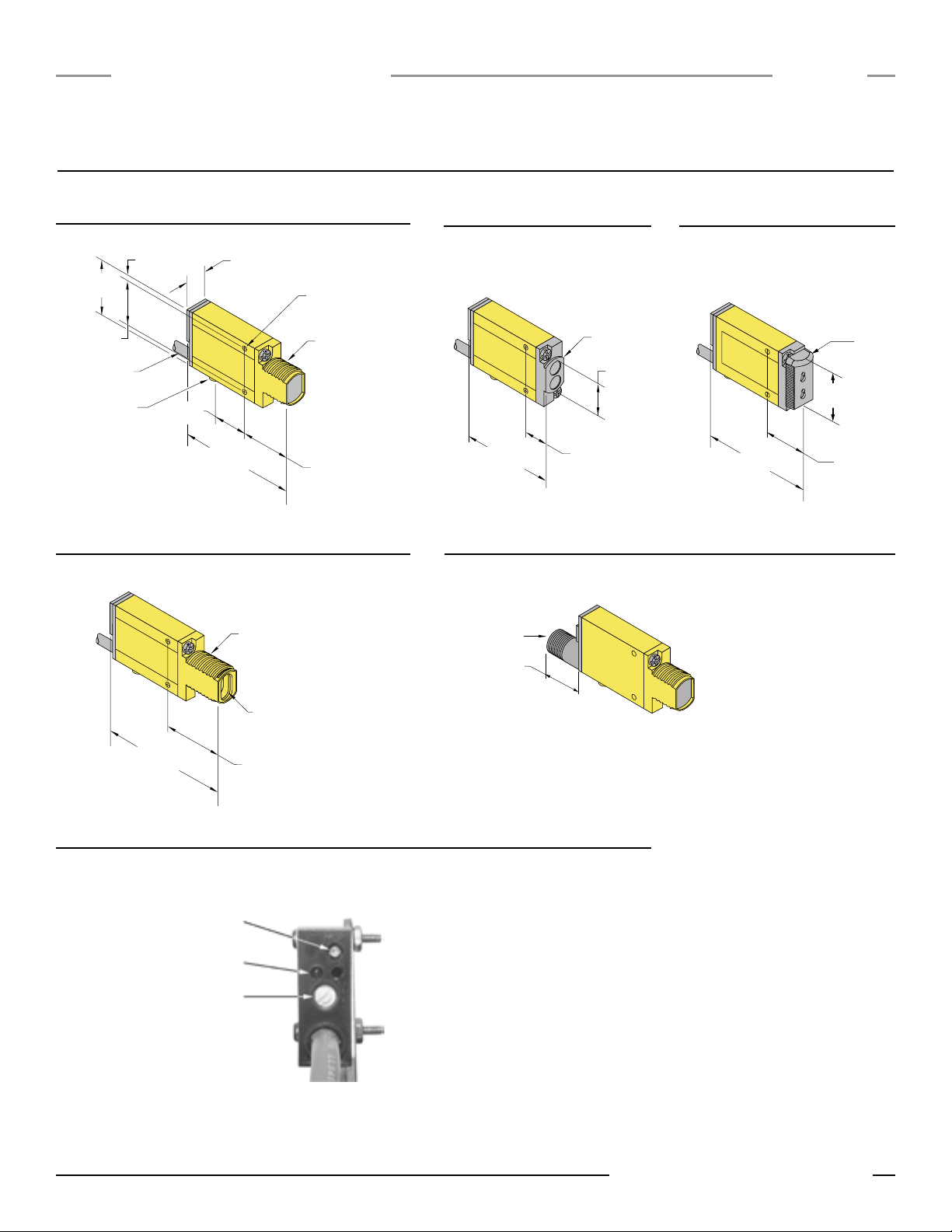
Gain (Sensitivity) Adjustment Screw
Alignment Indicator Device (AID)*
Light/Dark Operate Select Switch
Clockwise: Light Operate
(outputs conduct when sensing
light is received).
Counterclockwise: Dark Operate
(outputs conduct when sensing
light is not received).
*U.S. Patent no. 4356393
12.2 mm (0.48")
Mounting Peg
(ø 6.3 mm x 2.5 mm)
ø 3 mm Clearance (2)
M18 x 1 x 15 mm Thread
(Mounting Nut Supplied)
3.2 mm
(0.13")
27.4 mm (1.08")
30.7 mm
(1.21")
24.1 mm
(0.95")
19.1 mm
(0.75")
66.0 mm
(2.60")
2 m (6.5') Cable
Bezel
18.0 mm
(0.71")
51.8 mm
(2.04")
13.2 mm (0.52")
M18 x 1 x 19 mm Thread
(Mounting Nut Supplied)
Fiber Optic Fitting
69.9 mm
(2.75")
31.2 mm (1.23"
)
54.8 mm
(2.16")
Fiber
Optic
Fitting
22.3 mm
(0.88")
16.2 mm
(0.64")
20.0 mm
(0.79")
12 mm Thread
Quick-disconnect
MINI-BEAM
ac-Voltage Series
Models with suffixes E, EL, EPD, R, RL, RPD, LV,
LVAG, LP, D, C, C2, CV, CV2, and CVG
Dimensions
Models with suffix DBZ and W
Installation
Guide
Models with suffix FP
Models with suffix F and FV
2 P/N 69942 rev. A
(shown with gasketed acrylic cover removed)
Sensor Features
QD Models
NOTES:
• Please observe proper ESD precautions
(grounding) when adjusting Gain pot or
LO/DO switch.
• When turning the Light/Dark Operate Select
switch, be careful not to damage the small
tabs on the switch.
Banner Engineering Corp. • Minneapolis, MN U.S.A.
www.bannerengineering.com • Tel: 763.544.3164
Page 3

Installation
Object
Lo
w
Reflectivity
Backgr
ound
Retr
o
Ta
rg
et
Object
Object
Guide
Sensor Mounting and Alignment
MINI-BEAM sensors perform most reliably if they are properly aligned and securely
mounted. For maximum mechanical stability, final-mount MINI-BEAM sensors
through 18 mm diameter holes by their threaded barrel (where available), or use
a mounting bracket. A complete selection of mounting brackets is available. Visit
www.bannerengineering.com/69942, or contact the factory for information on
mounting options.
Begin with line-of-sight positioning of the MINI-BEAM sensor to its emitter
(opposed-mode sensing) or to its target (all other sensing modes). When using a
retroreflective sensor, the target is the retroreflector (“retro target”). For diffuse or
convergent sensing modes, the target is the object to be detected.
Apply power to the sensor (and to the emitter, if using the opposed mode).
Advance the 15-turn Gain control to maximum (clockwise end of rotation), using
a small flat-blade screwdriver. The Gain control is clutched at both ends to avoid
damage, and will “free-wheel” when either endpoint is reached. See Sensor
Features illustration on page 2.
Alignment Tips
®
MINI-BEAM
If the MINI-BEAM sensor is receiving its light signal, the red LED Alignment
indicator will be ON and flashing at a rate proportional to the signal strength
(faster = more signal). Move the sensor (or move the retro target, if applicable)
up-down-right-left (including angular rotation) to find the center of the movement
zone within which the LED indicator remains ON. Reducing the Gain setting will
reduce the size of the movement zone, and enable more precise alignment.
Repeat the alignment motions after each Gain reduction. When optimum
alignment is acheived, mount sensor(s) (and the retro target, if applicable) solidly
in that position. Increase the Gain to maximum.
Test the sensor by placing the object to be detected in the sensing position, then
removing it. The Alignment indicator LED should come ON when the sensing beam
is established (Light condition), and go OFF when the beam is broken (Dark
condition). If the Alignment indicator LED stays ON for both sensing conditions,
consider the following tips for each sensing mode.
ac-Voltage Series
Opposed-Mode Alignment
Light condition: no object in beam
Dark condition: object in beam
Emitter
Receiver
“Flooding” occurs when a portion of
the sensing beam passes around the object to
be sensed. “Burn-through” occurs when a portion
of the emitter’s light energy passes through a thin or
translucent object, and is sensed by the receiver.
To correct either problem, do one or more of the following to
reduce the light energy:
• Reduce the Gain adjustment on the receiver.
• Add an aperture to one or both lenses. (MINI-BEAM apertures, available from
Banner, fit neatly inside the lens assembly.)
• Intentionally misalign the emitter and receiver.
Retroreflective-Mode
Alignment
Light condition: no object in beam
Dark condition: object in beam
Diffuse-Mode Alignment
Light condition: object in beam
Dark condition: no object in beam
If the Alignment LED does not go
OFF when the object is removed
from the beam, the sensor is probably
detecting light reflected from some
background object. To remedy this problem:
• Reduce the reflectivity of the background by painting the
surface(s) flat-black, scuffing any shiny surface, or
drilling a large hole, directly opposite the diffuse sensor.
• Move the sensor closer to the object to be detected and reduce the Gain
adjustment. Rule of thumb for diffuse sensing: The distance to the nearest
background object should be at least three times the sensing distance.
Convergent-Mode Alignment
Light condition: object in beam
Dark condition: no object in beam
A highly reflective
object may reflect enough light
back to a retroreflective sensor to allow
that object to slip through the beam,
without being detected. This problem is called
“proxing,” and the following methods may be
used to correct it:
• Position the sensor and retro target so the beam will not
strike a shiny surface perpendicular to the sensor lens.
• Reduce the Gain adjustment.
• Add a polarizing filter (for model SM2A312LV).
Banner Engineering Corp. • Minneapolis, MN U.S.A.
www.bannerengineering.com • Tel: 763.544.3164
The sensing energy of a convergent-mode
sensor is concentrated at the specified focus
point (see page 1). Convergent-mode sensors are
less sensitive to background reflections, compared with
diffuse-mode sensors. However, if background reflections
are a problem:
• Skew the sensor position at a 10° to 25° angle to eliminate direct
reflections from shiny background surfaces.
• Reduce the reflectivity of the background by painting the surface(s)
flat-black, scuffing any shiny surface, or drilling a large hole, directly
opposite the sensor.
• Reduce the Gain adjustment.
P/N 69942 rev. A 3
Page 4

®
Trimmed fiber
control ends
Plastic fiber
emitter port
Plastic fiber
receiver port
Gripper
Unlock
Lock
Adapters for
0.25- and 0.5-mm fibers
Sensor Face
O-ring
Retaining Clip
MINI-BEAM
ac-Voltage Series
Installation
Guide
Fiber Installation
Glass Fiber Installation
1) Install the O-ring (supplied with the fiber) on each fiber end, as shown in the
drawing.
2) While pressing the fiber ends firmly into the ports on the sensor front, slide the
U-shaped retaining clip (supplied with the sensor) into the slot in the
sensor’s barrel, until it snaps into place.
Specifications
Supply Voltage and Current
24 to 240V ac (50/60 Hz), 250V ac maximum
Supply Protection Circuitry
Protected against transient voltages
Output Configuration
SPST SCR solid-state relay with either normally closed or normally open contact (“light/
dark operate” selectable); 2-wire hookup
Output Rating
Minimum load current 5 mA; maximum steady-state load capability 300 mA to 50°C
ambient (122°F) 100 mA to 70°C ambient (158°F)
Inrush capability: 3 amps for 1 second (non repetitive); 10 amps for 1 cycle (non
repetitive)
OFF-state leakage current: less than 1.7 mA rms
ON-state voltage drop: ≤ 5 volts at 300 mA load, ≤ 10 volts at 15 mA load
Output Protection Circuitry
Protected against false pulse on power-up
Output Response Time
Opposed: 2 millisecond on and 1 millisecond off;
Non-Polarized and Polarized Retro, Convergent, and Plastic Fiber Optic:
4 milliseconds on and off;
Diffuse and Glass Fiber Optic: 8 milliseconds on and off.
OFF response time specification does not include load response of up to 1/2 ac cycle (8.3
milliseconds). Response time specification of load should be considered when important.
(NOTE: 300 millisecond delay on power-up.)
Repeatability
Opposed: 0.3 milliseconds;
Non-Polarized and Polarized Retro, Convergent, and Plastic Fiber Optic:
1.3 milliseconds;
Diffuse and Glass Fiber Optic: 2.6 milliseconds.
Response time and repeatability specifications are independent of signal strength.
Plastic Fiber Installation
1) With supplied fiber cutter, make a clean cut at control ends of fibers.
2) Unlock the fiber gripper as shown below. Apply appropriate fiber adaptors
prior to fiber insertion, if needed.
3) Gently insert the prepared fiber ends into the ports, as far as they will go.
4) Slide the fiber gripper back to lock, as shown below.
Adjustments
Light/Dark Operate Select switch, and 15-turn slotted brass screw Gain (sensitivity)
adjustment potentiometer (clutched at both ends of travel). Both controls are located on the
rear panel of the sensor and are protected by a gasketed, clear acrylic cover (see page 2).
Indicators
Red indicator LED on rear of sensor is ON when the load is energized.
Construction
Reinforced thermoplastic polyester housing, totally encapsulated, o-ring sealing, acrylic
lenses, stainless steel screws
Environmental Rating
Meets NEMA standards 1, 2, 3, 3S, 4, 4X, 6, 12, and 13; IEC IP67.
Connections
PVC-jacketed 2-conductor 2 m (6.5') or 9 m (30') cables, or 3-pin Micro-style QD fitting;
QD cables available separately.
Operating Conditions
Temperature: -20° to +70°C (-4° to +158°F)
Maximum relative humidity: 90% at 50°C (non-condensing)
Application Notes
• Overload conditions can destroy ac MINI-BEAM sensors. Directly wiring sensor
without load series, across hot and neutral will damage sensor (except emitter models).
• Low-voltage use requires careful analysis of the load to determine if the sensor’s
leakage current or on-state voltage will interfere with proper operation of the load.
• The false-pulse protection feature may cause momentary drop-out of the load
when the sensor is wired in series or parallel with mechanical switch contacts.
Certifications
Additional information on this product is immediately available online at www.bannerengineering.com/69942
View or download additional information, including excess gain curves, beam patterns and accessories.
For further assistance, contact a Banner Engineering Applications Engineer at (763) 544-3164 or (888) 373-6767.
P/N 69942 rev. A
Banner Engineering Corp., 9714 Tenth Ave. No., Minneapolis, MN 55441 • Phone: 763.544.3164 • www.bannerengineering.com • Email: sensors@bannerengineering.com
WARRANTY: Banner Engineering Corp. warrants its products to be free from defects for one year.
Banner Engineering Corp. will repair or replace, free of charge, any product of its manufacture found to
be defective at the time it is returned to the factory during the warranty period. This warranty does not
cover damage or liability for the improper application of Banner products. This warranty is in lieu of any
other warranty either expressed or implied.
 Loading...