

Page 1
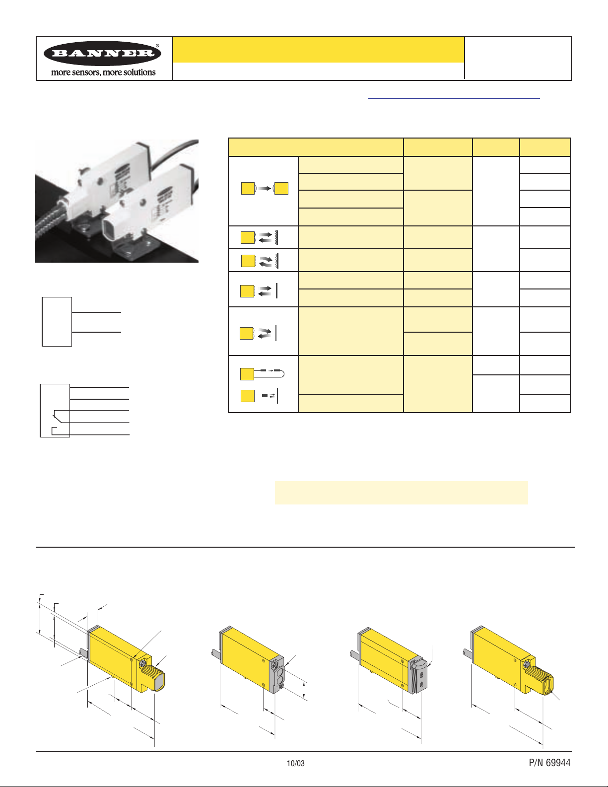
Opposed Receiver
Photoelectric sensors with electromechanical relay output
Printed in USA 10/03 P/N 69944
* Standard 2 m (6.5') cable models are listed. For 9 m (30') cable, add suffix “W/30” to the model number
(e.g., SMU31E W/30).
† Spot size (diameter of sensing beam) at focus.
Installation
Guide
Additional information on this product is immediately available online at www.bannerengineering.com/69944
View or download additional information, including excess gain curves, beam patterns and accessories.
For further assistance, contact a Banner Engineering Applications Engineer at (763) 544-3164 or (888) 373-6767.
bn
bu
+
-
24-240V ac/dc
Models with suffix
E, EL, R, RL, LV, LP, D, CV, and CV2
Model SMU315W
Models with suffix F and FV
Model SMU315FP
69.8 mm
(2.75")
Fiber Optic Fitting
16.2 mm (0.64")
NOTES:
• Output Type for all models (except emitters) is
SPDT Electromechanical Relay.
• Install transient suppressor (MOV) across contacts
switching inductive loads.
• Connection of dc power is without regard to polarity.
• Maximum switching current is 3 amps
(see specifications).
Divergent Diffuse
LED
Non-Polarized Retroreflective
Visible Red
650 nm
Polarized Retroreflective
Infrared
880 nm
Visible Red
650 nm
Diffuse
Model*
SMU315W
SMU315LV
SMU315LP
SMU315D
SMU315CV
Infrared
880 nm
Convergent
SMU31RL
Opposed Emitter
Infrared
880 nm
Opposed Emitter - Long Range
SMU315CV2
SMU31E
SMU315F
SMU31EL
SMU31R
Range
130 mm (5")
5 m (15')
10 mm to 3 m
(0.4" to 10')
380 mm (15")
16 mm (0.65")
1.3 mm (0.05")
†
43 mm (1.7")
3 mm (0.07")
†
3 m (10')
Range varies
depending on
sensing mode
and fiber
optics used
30 m (100')
Sensing Mode
Dimensions
Glass Fiber Optic
Plastic Fiber Optic
Opposed Receiver - Long Range
SMU315FP
Visible Red
650 nm
SMU315FV
Emitters
All Models Except Emitters
See Safety Use Warning on Back Page
MINI-BEAM®Universal Voltage Series
Opposed Receiver
Apr 2013
p/n 69944 Rev. A
bn
24-240V ac/dc
bu
wh
ye
bk
NC
C
NO
P
30.7 mm (1.21")
24.1 mm
(0.95")
2 m (6.5') Cable
Mounting Peg
ø 6.3 mm x 2.5 mm
(ø 0.25" x 0.10")
19.1 mm
(0.75")
12.2 mm (0.48")
81.0 mm
(3.19")
3.2 mm (0.13")
ø 3 mm (ø0.11")
Clearance (2)
M18 x 1 x 15 mm
Thread (Mounting
Nut Supplied)
27.4 mm
(1.08")
Bezel
18.0 mm
(0.71")
66.8 mm
(2.63")
13.2 mm (0.52")
Fiber Optic
Fitting
85.3 mm
(3.36")
31.2 mm
(1.23")
Page 2
2 P/N 69944
Banner Engineering Corp. • Minneapolis, MN U.S.A.
www.bannerengineering.com • Tel: 763.544.3164
MINI-BEAM®Universal Voltage Sensors
Installation
Guide
Installation and Alignment
MINI-BEAM sensors perform most reliably if they are properly aligned and
securely mounted. For maximum mechanical stability, final-mount MINI-BEAM
sensors through 18 mm diameter holes by their threaded barrel (where available),
or use a mounting bracket. A complete selection of mounting brackets is
available. Visit www.bannerengineering.com/69944, or contact the factory for
information on mounting options.
Begin with line-of-sight positioning of the MINI-BEAM sensor to its emitter
(opposed-mode sensing) or to its target (all other sensing modes). When using a
retroreflective sensor, the target is the retroreflector (“retro target”). For diffuse or
convergent sensing modes, the target is the object to be detected.
Apply power to the sensor (and to the emitter, if using the opposed mode).
Advance the 15-turn Gain control to maximum (clockwise end of rotation), using a
small flat-blade screwdriver. The Gain control is clutched at both ends to avoid
damage, and will “free-wheel” when either endpoint is reached. See MINI-BEAM
Sensor rear view illustration on page 2.
If the MINI-BEAM sensor is receiving its light signal, the red LED alignment
indicator will be ON and flashing at a rate proportional to the signal strength
(faster = more signal). Move the sensor (or move the retro target, if applicable)
up-down-right-left (including angular rotation) to find the center of the movement
zone within which the LED indicator remains ON. Reducing the Gain setting will
reduce the size of the movement zone, and enable more precise alignment.
Sensor Rear View
(shown with gasketed acrylic cover removed)
Repeat the alignment motions after each Gain reduction. When optimum
alignment is acheived, mount sensor(s) (and the retro target, if applicable) solidly
in that position. Increase the Gain to maximum.
Test the sensor by placing the object to be detected in the sensing position, then
removing it. The Alignment Indicator LED should come ON when the sensing
beam is established (Light condition), and go OFF when the beam is broken (Dark
condition).
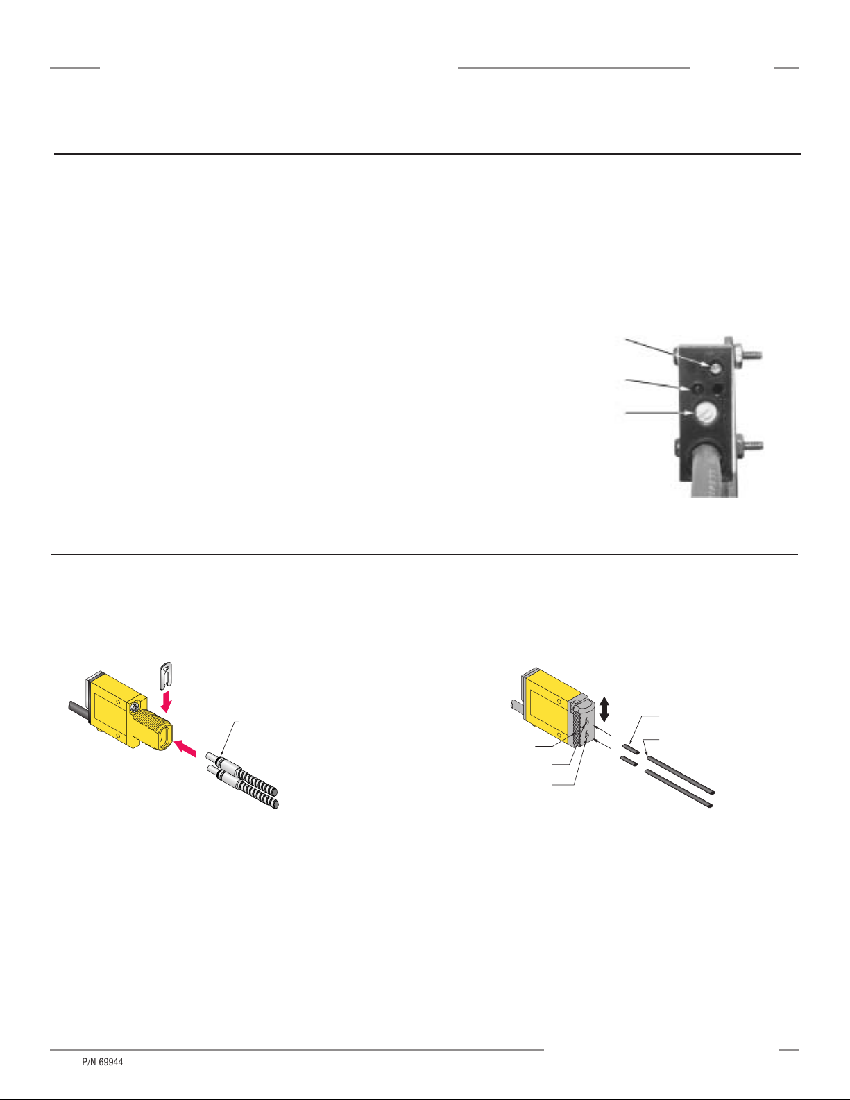
1) With supplied fiber cutter, make a clean cut at control ends of fibers.
2) Unlock the fiber gripper as shown below. Apply appropriate fiber adaptors
prior to fiber insertion, if needed.
3) Gently insert the prepared fiber ends into the ports, as far as they will go.
4) Slide the fiber gripper back to lock, as shown below.
Glass Fiber Installation
Plastic Fiber Installation
Trimmed fiber
control ends
Plastic fiber
emitter port
Plastic fiber
receiver port
Gripper
Unlock
Lock
Adaptors for
0.25- and 0.5-mm fibers
Sensor face
Fiber Installation
O-ring
Retaining Clip
1) Install the O-ring (supplied with the fiber) on each fiber end, as shown in the
drawing.
2) While pressing the fiber ends firmly into the ports on the front of the sensor,
slide the U-shaped retaining clip (supplied with the sensor) into the slot in the
sensor’s barrel, until it snaps into place.
p/n 69944 Rev. A
Gain (Sensitivity) Adjustment Screw
Alignment Indicator Device (AID)*
Light/Dark Operate Selection Switch
Clockwise: Light Operate
(outputs conduct when sensing
light is received).
Counterclockwise: Dark Operate
(outputs conduct when sensing
light is not received).
*U.S. Patent no. 4356393
Page 3

P/N 69944 3
Banner Engineering Corp. • Minneapolis, MN U.S.A.
www.bannerengineering.com • Tel: 763.544.3164
MINI-BEAM®Universal Voltage Sensors
Installation
Guide
The sensing energy of a convergent mode
sensor is concentrated at the specified focus
point (see chart on page 1). Convergent-mode
sensors are less sensitive to background reflections,
compared with diffuse-mode sensors. However, if
background reflections are a problem:
• Skew the sensor position at a 10° to 25° angle to eliminate direct
reflections from shiny background surfaces.
• Reduce the reflectivity of the background by painting the surface(s) flat-black,
scuffing any shiny surface, or drilling a large hole, directly opposite the sensor.
• Reduce the Gain adjustment.
“Flooding” occurs when a portion of the
sensing beam passes around the object to be
sensed. “Burn-through” occurs when a portion of the
emitter’s light energy passes through a thin or translucent
object, and is sensed by the receiver.
To correct either problem, do one or more of the following to reduce the light
energy:
• Reduce the Gain adjustment on the receiver.
• Add an aperture to one or both lenses. (MINI-BEAM apertures, available from
Banner, fit neatly inside the lens assembly.)
• Intentionally misalign the emitter and receiver.
If the alignment LED does not go OFF
when the object is removed from the
beam, the sensor is probably detecting
light reflected from some background object. To
remedy this problem:
• Reduce the reflectivity of the background by painting the
surface(s) flat-black, scuffing any shiny surface, or drilling
a large hole, directly opposite the diffuse sensor.
• Move the sensor closer to the object to be detected and reduce the Gain
adjustment. Rule of thumb for diffuse sensing: The distance to the nearest
background object should be at least three times the sensing distance.
Convergent-Mode Alignment
Light condition: object in beam
Dark condition: no object in beam
Alignment Tips
A highly reflective
object may reflect enough light back to a
retroreflective sensor to allow that object
to slip through the beam, without being
detected. This problem is called “proxing,” and
the following methods may be used to correct it:
• Position the sensor and retro target so the beam will not
strike a shiny surface perpendicular to the sensor lens.
• Reduce the Gain adjustment.
• Add a polarizing filter (for model SMU315LV).
Retro
Tar ge t
Retroreflective-Mode
Alignment
Light condition: no object in beam
Dark condition: object in beam
Opposed-Mode Alignment
Light condition: no object in beam
Dark condition: object in beam
Diffuse-Mode Alignment
Light condition: object in beam
Dark condition: no object in beam
p/n 69944 Rev. A
Receiver
Emitter
ct
je
b
O
Low
Reflectivity
Background
Object
Page 4

MINI-BEAM®Universal Voltage Sensors
Banner Engineering Corp., 9714 Tenth Ave. No., Minneapolis, MN 55441 • Phone: 763.544.3164 • Toll-free: 888.373.6767 • www.bannerengineering.com
Installation
Guide
WARNING . . .
Not To Be Used for Personnel Protection
Never use these products as sensing devices for personnel protection. Doing so could lead to serious injury or death.
These sensors do NOT include the self-checking redundant circuitry necessary to allow their use in personnel safety applications. A
sensor failure or malfunction can cause either an energized or de-energized sensor output condition. Consult your current Banner Safety Products
catalog for safety products which meet OSHA, ANSI and IEC standards for personnel protection.
Additional information on this product is immediately available online at www.bannerengineering.com/69944
View or download additional information, including excess gain curves, beam patterns and accessories.
For further assistance, contact a Banner Engineering Applications Engineer at (763) 544-3164 or (888) 373-6767.
WARRANTY: Banner Engineering Corp. warrants its products to be free from defects for one year. Banner Engineering Corp. will repair or replace, free of
charge, any product of its manufacture found to be defective at the time it is returned to the factory during the warranty period. This warranty does not
cover damage or liability for the improper application of Banner products. This warranty is in lieu of any other warranty either expressed or implied.
Specifications
Supply Voltage and Current
24 to 240V ac, 50/60 Hz or
24 to 240V dc (1.5 watts or 2.5 VA maximum)
Supply Protection Circuitry
Protected against transient voltages. DC hookup is without regard to polarity.
Output Configuration
SPDT (Single-Pole, Double Throw) (form C) electromechanical relay, ON/OFF output.
Output Rating
Maximum switching power (resistive load): 90W, 250VA
Maximum switching voltage (resistive load): 250V ac or 30V dc
Maximum switching current (resistive load): 3A
Minimum voltage and current: 5V dc, 10 mA
Mechanical life: 20,000,000 operations
Electrical life at full resistive load: 100,000 operations
Output Protection Circuitry
Protected against false pulse ON power-up.
Output Response Time
Closure time: 20 milliseconds max.
Release time: 20 milliseconds max.
Maximum switching speed: 25 operations per second
Repeatability
All sensing modes: 1millisecond
Adjustments
Light/Dark Operate select switch
15-turn slotted brass screw Gain (sensitivity) adjustment potentiometer
Located on rear panel, protected by a gasketed, clear acrylic cover (see above)
Indicators
Patented Alignment Indicator Device system (AID™) lights a rear-panel-mounted LED
indicator whenever the sensor sees a “light” condition. Its pulse rate is proportional to the
light signal strength (the stronger the signal, the faster the pulse rate).
Construction
Reinforced thermoplastic polyesterhousing, totally encapsulated, o-ring seal, acrylic lenses,
and stainless steel screws.
Environmental Rating
Meets NEMA standards 1, 2, 3, 3S, 4, 4X, 63, 12, and 13; IEC IP67.
Connections
PVC-jacketed 5-conductor (2-conductor for emitters) 2 m (6.5') or
9 m (30') unterminated cable.
Operating Conditions
Temperature: -20° to +55°C (-4° to +131°F)
Maximum relative humidity: 90% at 50°C (non-condensing)
Application Note
Install transient suppressor (MOV) across contacts switching inductive loads.
P/N 69944
Banner Engineering Corp Limited Warranty
Banner Engineering Corp. warrants its products to be free from defects in material and workmanship for one year following the date of shipment. Banner Engineering Corp. will repair or replace, free of charge, any product of its manufacture which, at
the time it is returned to the factory, is found to have been defective during the warranty period. This warranty does not cover damage or liability for misuse, abuse, or the improper application or installation of the Banner product.
THIS LIMITED WARRANTY IS EXCLUSIVE AND IN LIEU OF ALL OTHER WARRANTIES WHETHER EXPRESS OR IMPLIED (INCLUDING, WITHOUT LIMITATION, ANY WARRANTY OF MERCHANTABILITY OR FITNESS FOR A PARTICULAR
PURPOSE), AND WHETHER ARISING UNDER COURSE OF PERFORMANCE, COURSE OF DEALING OR TRADE USAGE.
This Warranty is exclusive and limited to repair or, at the discretion of Banner Engineering Corp., replacement. IN NO EVENT SHALL BANNER ENGINEERING CORP. BE LIABLE TO BUYER OR ANY OTHER PERSON OR ENTITY FOR ANY
EXTRA COSTS, EXPENSES, LOSSES, LOSS OF PROFITS, OR ANY INCIDENTAL, CONSEQUENTIAL OR SPECIAL DAMAGES RESULTING FROM ANY PRODUCT DEFECT OR FROM THE USE OR INABILITY TO USE THE PRODUCT,
WHETHER ARISING IN CONTRACT OR WARRANTY, STATUTE, TORT, STRICT LIABILITY, NEGLIGENCE, OR OTHERWISE.
Banner Engineering Corp. reserves the right to change, modify or improve the design of the product without assuming any obligations or liabilities relating to any product previously manufactured by Banner Engineering Corp.
p/n 69944 Rev. A
 Loading...