

Page 1
Specifications
®
MICRO-AMP
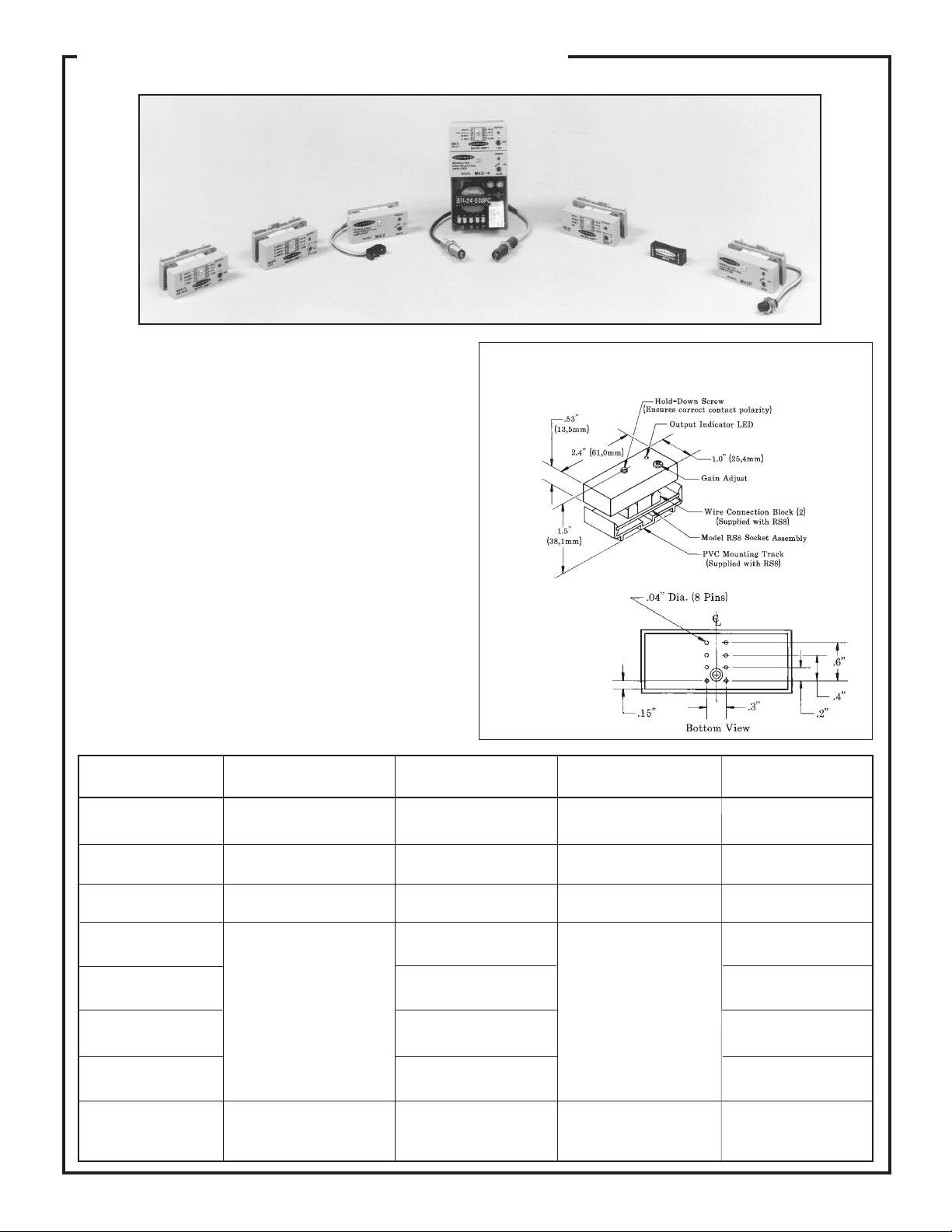
Remote sensors, modulated amplifiers, and logic modules
System
Product
Line
A versatile system of compact, high-performance remote
•
sensors modulated amplifiers, and logic modules
Remote sensors for opposed, retro, diffuse, convergent, and
•
fixed-field sensing modes, in a variety of sizes, shapes, and
housing styles to suit nearly any remote sensing application
Rugged, epoxy-encapsulated amplifier modules; also logic
•
modules for one-shot, 4-input gate (AND, NOR, XNOR),
latch, and delay functions
Plug-in amplifier and logic modules are track mountable for
•
ease of installation and replacement (helpful in large systems)
All modules have an output indicator for system monitoring;
•
amplifier modules include Banner's exclusive AID™ indicator
system
Printed in USA P/N 32885
Page 2
MICRO-AMP® System
The Banner MICRO-AMP® System is a family of miniature dc modulated photoelectric amplifiers and logic modules which offer the same
sensing performance as larger, conventional modules. They are the
smallest photoelectric control modules ever built, and can fit easily into
tight areas of machines or control panels. Built around the concept of
an I/O module, they are the perfect photoelectric control device for use
with computers or programmable logic controllers (PLCs). Multiple
modules stack neatly on 1-inch (25mm) centers in PVC mounting
track, taking only a fraction of the control panel space required by
standard photoelectric modules.
Model MA3 is a complete dc-powered modulated amplifier designed
for use with Banner's SP100 Series of miniature remote sensors.
Model MA3-4 is a higher-gain amplifier which is used with Banner's
complement of high-performance modulated remote sensors. Building-block style control logic may be added to a system with a selection
of MICRO-AMP logic modules.
Model MPC3 is similar to amplifier model MA3, except that it is
specifically designed for PC board mounting in OEM sensing applications.
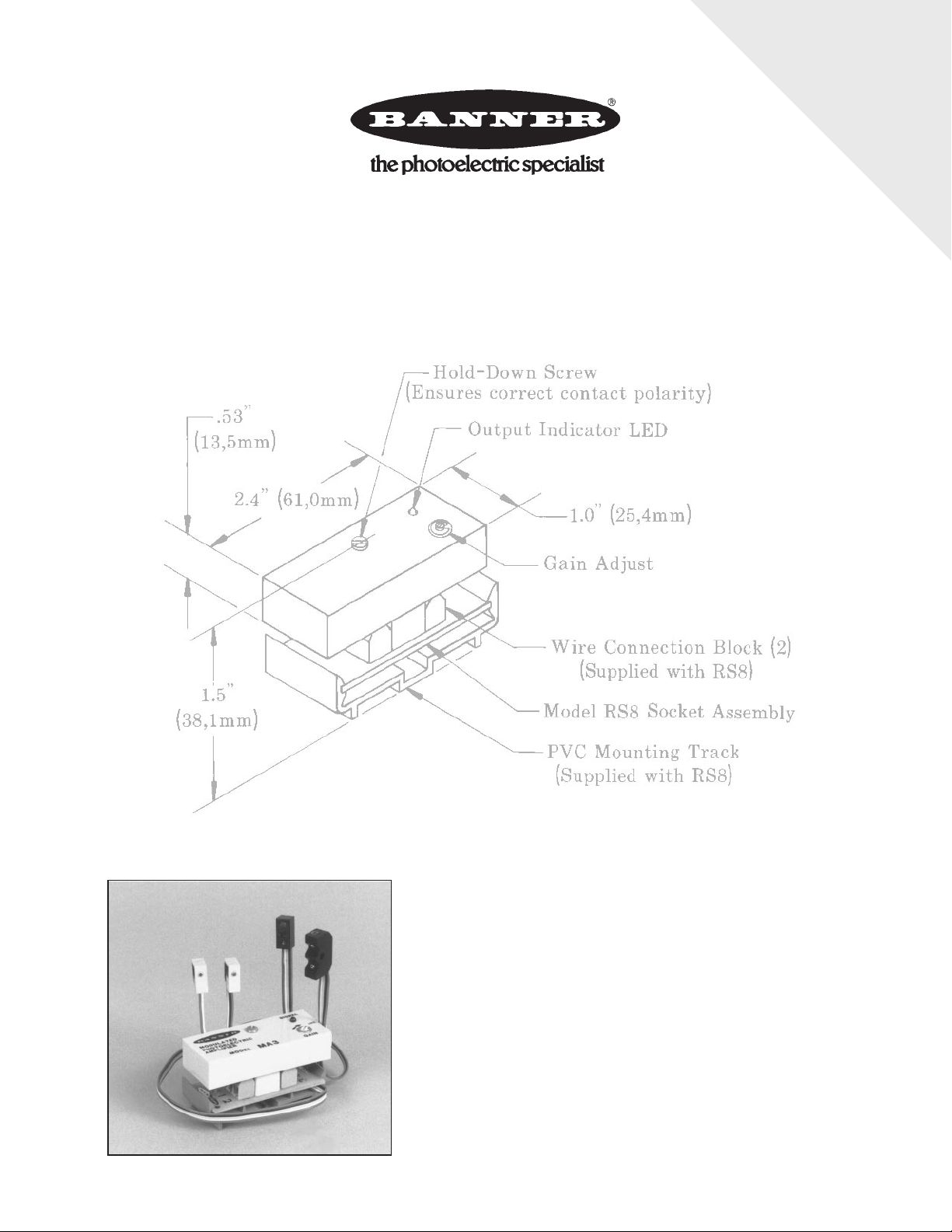
MICRO-AMP modules may be mounted and wired using the optional
model RS8 socket (shown in the drawing at right) or they may be
mounted directly to a printed circuit board (see Accessories, p. 20).
Module
Model
MA3
MA3A
Modulated
Amplifier
YES
Logic Functions Used with (Input) Full Description
NONE (ON/OFF)
NONE (ON/OFF)
Dimension Drawing, MICRO-AMP Modules
(except MPC3) with RS8 Wiring Socket
MICRO-AMP
module pin
configuration
Banner SP100 Series
miniature modulated
remote sensors
Banner SP100FF modulated fixed-field sensor
See pages 3-4YES
See page 18
MA3-4
MA4-2
MA4G
MA4L
MA5
MPC3
(for printed circuit
board mounting)
2
YES
MICRO-AMP logic
modules are designed to
accept the output signal
from a MICRO-AMP
amplifier and process
that signal for a required
logic function. MICROAMP logic modules
themselves contain no
amplifier.
YES
NONE (ON/OFF)
ONE-SHOT
4-input logic gate:
AND, NOR, X-NOR
Latch or alternate-action
flip-flop
ON-delay or OFF-delay
NONE (ON/OFF)
Banner high-performance
remote sensors
Switches, contacts, or
NPN (current sinking)
output of dc sensors or
amplifiers, including:
Banner MULTI-BEAM,
MAXI-BEAM, VALUBEAM, MINI-BEAM,
and ECONO-BEAM
sensors; plus
MAXI-AMP and
MICRO-AMP modules.
Banner SP100 Series miniature modulated remote
sensors
See pages 5-10
See page 11
See page 12
See page 13
See page 14
See pages 15-16, 18
Page 3
MICRO-AMP® System
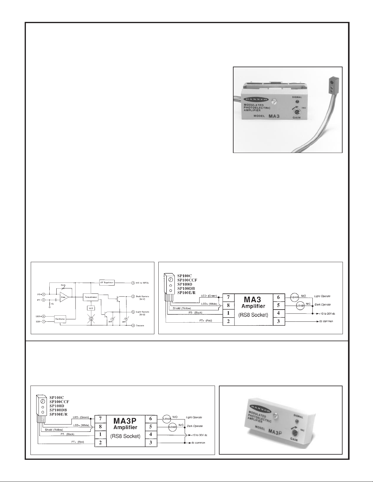
MA3 and MA3P Modulated Amplifiers
Banner MICRO-AMP® modules MA3 and MA3P are modulated amplifiers designed
for use with SP100 Series miniature remote sensors. Miniature photoelectric sensors
have traditionally been used as non-modulated devices with very limited response.
MICRO-AMP amplifiers have a specially-engineered modulated design which brings
about a dramatic improvement in the optical performance of miniature remote sensors.
MICRO-AMP modules are powered by 10 to 30 volts dc, and feature the patented Banner
Alignment Indicator Device (AID™) signal strength LED. Sensor sensitivity is adjustable
via a top-mounted GAIN potentiometer. Model MA3 has complementary current sinking
(NPN) outputs; model MA3P has complementary current sourcing (PNP) outputs.
Circuitry is epoxy-encapsulated and enclosed in a tough molded VALOX
Connections may be made to the MICRO-AMP via the optional RS8 socket/wiring base,
or the module may be mounted directly to a printed circuit board (page 20).
The small size and the slim ribbon-style connecting cable of SP100 Series sensors make
it possible to use photoelectrics in many situations previously thought to be impractical or even impossible.
®
housing.
MICRO-AMP® Model MA3 Specifications
SUPPLY VOLTAGE: 10 to 30V dc at less than 20 milliamps
(exclusive of load); 10% maximum ripple.
OUTPUT CONFIGURATION: two open-collector NPN (current
sinking) transistor (solid-state) switches; one normally open (light
operate) and one normally closed (dark operate); 150 milliamps
maximum, each output. Saturation voltage less than 0.5V dc at 10
milliamp load. Off-state leakage current less than 1 microamp.
RESPONSE SPEED: 1 millisecond ON and OFF.
REPEATABILITY: 0.3 millisecond.
SENSOR LEAD LENGTH: 15 feet (4,5 m) maximum.
Functional Schematic, MA3 Amplifier
ADJUSTMENT: GAIN adjustment (single-turn potentiometer;
adjust with small flat-blade screwdriver).
INDICATOR: exclusive Banner Alignment Indicator Device
(AID™) system lights a red LED indicator whenever the sensor
"sees" its own modulated light source, and pulses at a rate proportional to the strength of the received light signal.
CONSTRUCTION*: totally encapsulated plug-in package with
molded VALOX
OPERATING TEMPERATURE:
0 to +70 degrees C (32 to +158 degrees F).
*A Dimension Drawing appears on page 2.
®
housing. Gold-flashed connection pins.
Hookup Diagram, MA3 Amplifier
Model MA3P: PNP (current sourcing) output
Model MA3P has the same specifications and performance as the MA3 amplifier, except that the MA3P has complementary PNP outputs in
place of the MA3's NPN configuration.
OUTPUT: two PNP transistors, complementary outputs; one normally open (light operate) and one normally closed (dark operate). 150 milliamps
maximum, each output. Saturation voltage is less than 1V dc at 10 milliamps. Off-state leakage current is less than 1 microamp.
Hookup Diagram, MA3P Amplifier
3
Page 4
n
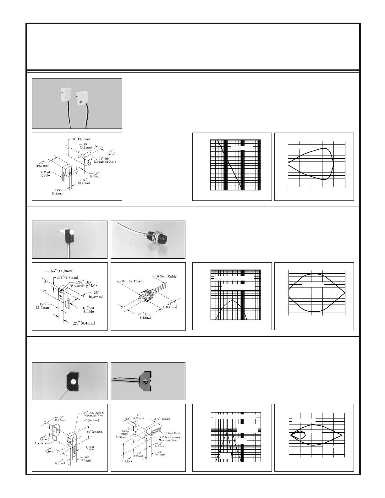
Sensors for use with MA3 and MA3P Modulated Amplifiers
Temperature range for all miniature modulated remote sensors is 0 to 70 degrees C (+32 to 158 degrees F).
Sensors are epoxy-encapsulated and optics are hermetically sealed.
Models/Dimensions Excess Gain Beam Pattern
SP100D
SP100E &
SP100R
Range: 8 inches (20cm)
Beam: infrared, 880nm
Effective beam: .05 inch
(1,3mm diameter)
Cable (all 6-foot lengths):
SP100E: 2-wire ribbon cable
(white, green).
SP100R: 3-wire ribbon cable
(red, black, yellow).
SP100D, DB, C, CCF: 5-wire
ribbon cable (white, green,
red, black, yellow). See
hookup drawing.
SP100DB
OPPOSED Mode Sensors
SP100E and SP100R miniature opposed sensors have a slim right-angle design
which allows them to be mounted in very tight locations. The thin, flexible
ribbon cable which exits from one corner may be run in any direction away from
the sensing point. The SP100E and R have a wide beam angle for forgiving lineof-sight alignment. Alignment is easily made exact (and monitored) using the
AID™ LED on the MICRO-AMP module.
1000
1.5
E
X
100
C
E
S
S
G
10
A
I
I
N
1
.1 IN
SP100E/R
1 IN
DISTANCE
10 IN 100 IN
SP100E/R
1
I
.5
N
C
0
H
E
.5
S
1
1.5
20
OPPOSED DISTANCE --INCHES
4 6 8 10
DIFFUSE Mode Sensors
Models SP100D and SP100DB are general-purpose miniature diffuse sensors
which detect the reflection of their own light from the surface of an object. The
SP100D is a right-angle design which is generally held in place using a #4 (3mm)
screw. The SP100DB ("B" = Barrel) is an in-line threaded barrel which typically
mounts through a 3/8" (10mm) diameter hole using the lock nuts which are
supplied. The optical response characteristics of these two sensors are identical.
SP100C
SP100CCF
1000
SP100D, SP100DB
E
X
100
C
E
S
S
G
10
A
I
I
N
1
.01 IN .1 IN
Range based on 90%
reflectance white test card
1 IN 10 IN
DISTANCE
.1
.05
I
N
C
H
E
S
SP100D, DB
0
.05
.1
.30
DISTANCE TO 90% WHITE TEST CARD--INCHES
.6 .9 1.5
1.2
CONVERGENT Mode Sensors
Models SP100C and CCF are ideally suited to applications where depth of field
is critical. The emitter and receiver are both directed at a point 0.1 inch (2,5mm)
ahead of the front surface. An aperture is included which, when attached,
narrows the depth of field (see curves, below). This is particularly useful when
it is necessary to detect an object while ignoring another object or a surface just
a fraction of an inch farther away. The high excess gain at the focus allows
detection of objects of low reflectivity. The SP100C and CCF differ only in
housing style. Model SP100C is for general application. Model SP100CCF is
used where a narrow profile is important for mounting.
1000
SP100C, SP100CCF
E
X
100
C
E
S
S
G
10
A
I
I
N
with
aperture
1
.01 IN .1 IN
DISTANCE
(Range based o
90% reflectance
white test card)
without
aperture
1 IN 10 IN
SP100C, CCF
.1
I
.05
N
C
0
H
E
.05
S
.1
DISTANCE TO 90% WHITE TEST CARD--INCHES
with aperture
without aperture
0
.15
.30 .45 .60 .75
4
Page 5
MICRO-AMP® System
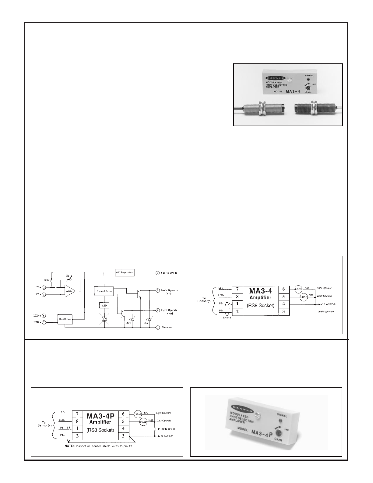
MA3-4 and MA3-4P Modulated Amplifiers
Banner MICRO-AMP® module models MA3-4 and MA3-4P are modulated amplifiers designed for use with the popular family of Banner high-performance remote
sensors. When these modulated remote sensors are used with the MA3-4 or MA3-4P,
their optical response is the same as when they are used with the larger MAXI-AMP™
CM Series modules.
These modules are powered by 10 to 30 volts dc. They feature the patented Banner
Alignment Indicator Device (AID™) signal strength LED. Sensor sensitivity is
adjustable via a top-mounted GAIN potentiometer. Circuitry is epoxy-encapsulated
and protected by a tough molded VALOX
these modules via the optional RS8 socket/wiring base, or the module may be mounted
directly to a printed circuit board.
The sensors which are used with these modules are totally encapsulated for durability and infinite life. Wide beam angles eliminate
alignment problems, and high optical gain permits reliable sensing under severe conditions.
MICRO-AMP MA3-4 Specifications
SUPPLY VOLTAGE: 10 to 30V dc at less than 20 milliamps
(exclusive of load); 10% maximum ripple.
OUTPUT CONFIGURATION: two open-collector NPN (current
sinking) transistor (solid-state) switches; one normally-open (light
operate) and one normally closed (dark operate). 150 milliamps
maximum, each output. Saturation voltage less than 0.5V dc at 10
milliamp load. Off-state leakage current less than 1 microamp.
RESPONSE SPEED: 1 millisecond ON and OFF.
REPEATABILITY: 0.3 millisecond.
SENSOR LEAD LENGTH: 30 feet (9m) maximum.
®
housing. Connections may be made to
ADJUSTMENT: GAIN adjustment (single-turn potentiometer; adjust with small flat-blade screwdriver).
INDICATOR: exclusive Banner Alignment Indicator Device
(AID™) system lights a red LED indicator whenever the sensor "sees"
its own modulated light source, and pulses at a rate proportional to the
strength of the received light signal.
CONSTRUCTION: totally encapsulated plug-in package with
molded VALOX
OPERATING TEMPERATURE:
-40 to +70 degrees C (-40 to +158 degrees F).
®
housing. Gold-flashed connection pins.
Functional Schematic, MA3-4
Hookup Diagram, MA3-4
Model MA3-4P: PNP (current sourcing) output
Model MA3-4P has the same specifications and performance as the MA3-4 amplifier, except that the MA3-4P has complementary PNP outputs
in place of the MA3-4's NPN configuration.
OUTPUT: two PNP transistors, complementary outputs; one normally open (light operate) and one normally closed (dark operate). 150
milliamps maximum, each output. Saturation voltage less than 1V dc at 10 milliamps. Off-state leakage current less than 1 microamp.
Hookup Diagram, MA3-4P
5
Page 6
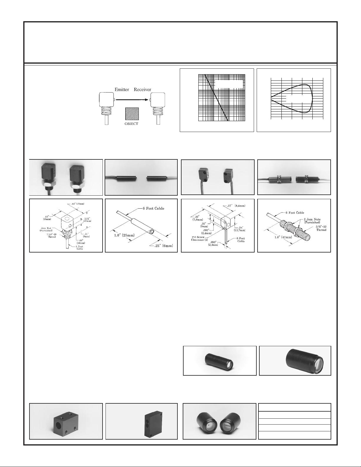
Sensors for use with MA3-4 and MA3-4P Modulated Amplifiers
Sensors are epoxy-encapsulated and optics are hermetically sealed. Cables are 6 -1/2 feet (2m) long. 30-foot (9m) cables available by special order.
Models/Dimensions
OPPOSED Mode
ALL MODELS
Range: 8 feet (2,4m)
Beam: infrared, 880nm
Effective Beam:
0.14 inch (3,6mm) dia.
PT models are receivers
LR models are emitters
LR200 & PT200
Temp. range: -40 to +100°C
Housing material: black Delrin
LR250 & PT250 LR300 & PT300 LR400 & PT400
Temp. range: -40 to +100°C
®
Housing material: black Delrin
Excess Gain
1000
E
X
C
100
E
S
S
G
10
A
I
I
N
1
.1 FT 1 FT 10 FT 100 FT
Temp. range: -40 to +80°C
®
Housing material: black VALOX
LR/PT200, 250,
300, & 400
DISTANCE
Beam Pattern
12
8
I
4
N
C
0
H
E
4
S
8
12
Temp. range: -40 to +100°C
®
Housing material: anod. aluminum
LR/PT200, 250,
300, 400
20
4 6 8 10
OPPOSED DISTANCE--FEET
LR/PT200, 250, 300, and 400 opposed mode remote sensors are
identical electronically and optically, and differ only in their housings.
All are totally epoxy-encapsulated and use hermetically sealed glass
lenses to eliminate condensation inside the optical chamber. These
sensors may be washed down without damage. Operating temperature
is determined by the type of cable used (see specifications above). All
models have a wide beam angle for forgiving line-of-sight alignment.
At the same time, the effective beam of each pair is only 1/8 inch,
allowing small-profile resolution and reliable response to fast-moving
objects. LR models are emitters, and PT models are receivers.
LR200 & PT200: this is a right-angle design which mounts through
a 7/16 inch (12mm) diameter hole, using the steel jam nut which is
included. This pair is used most commonly on small conveyors when
it is desireable to run the cable directly down to a wireway.
LR250 & PT250: these sensors feature a 1/4 inch (6,4mm) diameter
smooth barrel design, and are usually held in place in a clearance hole
with a small set-screw. Optional mounting blocks (shown below) are
available. Model SMB250 holds the sensor in place with two setscrews. The block is then mounted to a bracket (such as model
SMB300), or directly to a machine frame with two #6 screws. Block
model SMB250C holds an LR & PT250 together to converge at
approximately 1/2 inch ahead of the block.
SMB250 SMB250C
LR & PT300: this is a miniature right-angle design which is mounted
in place using two #4 screws. This pair uses a very flexible, lowprofile 2-wire cable. Despite their small size, the optical performance
of the LR/PT300 is equal to the other remote sensor pairs.
LR400 & PT400: the 3/8 inch (9,5mm) diameter threaded barrel
design makes the LR/PT400 the most versatile and most popular
remote opposed sensor pair. They are easily mounted through clearance holes using the jam nuts which are supplied. They may be used
with optional L4 or L16 lenses for extended range and/or higher excess
gain. The addition of an L4 lens on both the LR and PT400 will
increase their range from 8 feet to 40 feet and increase the excess gain
at any distance by a factor of 25X. A pair of L16 lenses will increase
available excess gain by a factor of 250X.
L4 lens
The LR/PT400 pair is often used at close range with optional AP400 aperture
assemblies to create a very small and well-defined effective beam for resolving
small profiles, increasing sensing repeatability, or easing response time requirements.
AP400 apertures
L16 lens
Aperture model
AP400-010
AP400-015
AP400-040
AP400-030R
Aperture size
.010" dia.
.015" dia.
.040" dia.
.030" x .125"
6
Page 7

Sensors for use with MA3-4 and MA3-4P Modulated Amplifiers
Sensors are epoxy-encapsulated. Cables are 6-1/2 feet (2m) long. 30-foot (9m) cables available by special order.
Models/Dimensions Excess Gain Beam Pattern
SP300EL & SP300RL
Range: 50 feet (15m)
Effective Beam: .5 inch (13mm)
dia.
Emitter-receiver pair SP300EL/RL are extremely rugged and are totally
encapsulated in anodized aluminum housings. The threaded hub at the cable
exit allows for the use of flexible armored cable or protective PVC tubing with
the addition of compression gland model CF7-16. This pair uses collimating
Temp. range: -40 to +100°C
Housing material: anodized
aluminum
SP300L
Range: 15 feet (4,5m)
with BRT-3 retroreflector
Temp. range: -40 to +80°C
Housing material: blue anodized
aluminum
Long Range
OPPOSED Mode
1000
SP300EL/RL
E
X
C
100
E
S
S
SP300EL/RL
G
10
A
I
I
N
1
.1 FT 1 FT 10 FT 100 FT
DISTANCE
18
12
I
6
N
C
0
H
E
6
S
12
18
20
100
OPPOSED DISTANCE --FEET
30 40 50
lenses to increase range. These sensors should also be used at short ranges for
their high excess gain or to avoid optical "crosstalk" in situations which require
several pairs to be mounted adjacent to one another.
RETROREFLECTIVE
Mode
Model SP300L is a remote retroreflective sensor with the same rugged design
as the SP300EL/RL, described above. Its useable range is from 6 inches to 15
feet (0,2 to 4,5m) using the model BRT-3 retroreflector.
LP400WB
DIVERGENT Mode
Range: 3 inches (76mm)
Temp. range: -40 to +80°C
Housing material: blue anodized
aluminum
"WB" in this model number designates "wide beam". The LP400WB is an
infrared divergent mode (wide angle diffuse mode) sensor which is particularly forgiving for reflectively sensing transparent or translucent materials or
1000
E
X
100
C
E
S
S
G
10
A
I
I
N
SP300L
with
BRT-T tape
with
BRT-1 target
1
.1 FT 1 FT 10 FT 100 FT
DISTANCE
with
BRT-3 target
6
4
I
2
N
C
0
H
E
2
S
4
6
SP300L
with BRT-3 reflector
40
8 12 15 18
DISTANCE TO REFLECTOR--FEET
If the object that is to break the beam has a shiny surface, then the SP300L and
its retroreflector should be mounted so that the beam is at an angle of 10 degrees
or more to that surface in order to eliminate false signals which are caused by
proxing.
1000
LP400WB
E
X
100
C
E
S
S
G
10
A
I
I
N
1
.1 IN 1 IN 10 IN 100 IN
Range based on
90% reflectance
white test card
DISTANCE
1.5
1.0
I
.5
N
C
0
H
E
.5
S
1.0
1.5
DISTANCE TO 90% WHITE TEST CARD--INCHES
LP400WB
10
2 3 4 5
for sensing objects with irregular surfaces (e.g.- webs with "flutter"). The optics
are such that even small threads or wires .005" (0,1mm) or greater in diameter
may be detected when they pass within .25" (6mm) of the sensor's plastic lens.
Due to its wide response pattern, the LP400WB should not be used for precise
positioning control, nor should it be mounted with its lens recessed into a hole.
7
Page 8

Sensors for use with MA3-4 and MA3-4P Modulated Amplifiers
Sensors are epoxy-encapsulated. Cables are 6-1/2 feet (2m) long. 30-foot (9m) cables available by special order.
Models/Dimensions
SP300D
Range: 12 inches (30cm) both models
Housing material (SP300D):
green anodized aluminum
SP320D
Temp. range: -40 to +80°C both
models
Housing material (SP320D):
black VALOX
®
Excess Gain Beam Pattern
DIFFUSE
Mode
1000
SP300D, SP320D
E
X
100
C
E
S
S
G
10
A
I
I
N
1
.1 IN 1 IN 10 IN 100 IN
DISTANCE
.6
.4
I
.2
N
C
0
H
E
.2
S
.4
.6
DISTANCE TO 90% WHITE TEST CARD--INCHES
SP300D: the SP300D is the diffuse mode version of the SP300L with the same
rugged aluminum housing and totally encapsulated construction. The glass
lenses are hermetically sealed, which eliminates any possibility of condensation inside the lenses and allows operation in adverse environments like steam
washdown and high vibration. The SP300D may be mounted by its throughholes or with the SMB300 bracket, as shown below.
SP320D: model SP320D is identical to the SP300D, except for its housing.
The 320 is a miniature plastic package, designed to fit into very tight locations.
It mounts using two #4 (3mm) screws. The SP320D and the SP300D are
excellent for nearly any presence sensing application.
SP300D, 320D
30
6 9 12 15
SMB300
Universal Mounting
Bracket for
SP300 Sensors
SP1000V
Range: focus at 3.8 inches (96mm)
Temp. range: -40 to +80 degrees C
Housing material: black anodized
aluminum
CONVERGENT Mode
Accessory bracket model SMB300 is designed for 2-axis universal
mounting of sensor models SP300EL, SP300RL, SP300L, and SP300D.
These sensors are affixed to the SMB300 with two #6 (3,5mm) screws.
The bracket, in turn, mounts with two #10 (5mm) screws.
In addition, as indicated by the dimension drawing, the SMB300 has a
clearance slot for mounting LR400, PT400, and LP400WB barrel
sensors. LR & PT200 sensors may be mounted with the SMB300, using
its 7/16-20 threaded hole and steel jam nut, which is supplied with the
sensors. LR250 and PT250 sensors may be used with the SMB300 when
the SMB250 block is used. Also, two SMB250 blocks may be attached
to the SMB300 bracket and angled to mechanically converge an LR &
PT250 sensor pair.
The SP1000V is a convergent mode sensor that produces a very small 0.1
inch (2,5mm) diameter sensing image at a point exactly 3.8 inches (96mm)
from its glass lenses. As the excess gain curve illustrates, the SP1000V has
a very sharp drop-off of gain beyond the focus point. This feature makes it
an excellent choice for detecting a small part which is only a fraction of an
inch in front of another surface, such as parts on a conveyor (viewed from
above). It is also ideal for fill level detection and for precise positioning
control, in lieu of opposed sensing.
1000
E
SP1000V
X
100
C
E
S
S
G
10
A
I
I
N
1
.1 IN 1 IN 10 IN 100 IN
DISTANCE
.090
.060
I
.030
N
C
0
H
E
.030
S
.060
.090
10
DISTANCE TO 90% WHITE TEST CARD--INCHES
SP1000V
2 3 5 4
8
Page 9

Sensors for use with MA3-4 and MA3-4P Modulated Amplifiers
Sensors are epoxy-encapsulated and optics are hermetically sealed. Cables are 6-1/2 feet (2m) long. 30-foot (9m) cables available by special order.
FIBER OPTIC Mode
glass fiber optics
FOF-400 fiberoptic fitting
LR400 & PT400
with FOF-400 fittings
and fiber optics
Range: see excess gain curves
Temp. range: -40 to +100°C
The threaded barrel design of the
LR400 and PT400 permit the connection of any Banner glass fiber
optic assembly by using two model
FOF-400 fittings. The sensors are
typically mounted through a 3/8
inch (10mm) diameter clearance
hole, with the FOF-400 fittings
threaded onto them after mounting.
Setscrews in the fittings lock the
fibers in place, but allow rapid replacement without disturbing any
electrical wiring.
As the excess gain curves show, the
LR/PT400 combination produces a
high-performance fiber optic sensing system. With the amplifier's 1
millisecond response time, this system can be used for almost any fiber
optic requirement.
Fiber optic information:
IT13S: individual assembly
.06 in. (1,5mm) dia. bundle
IT23S: individual assembly
.12 in. (3mm) dia. bundle
BT13S:bifurcated assembly
.06 in. (1,5mm) dia. bundle
BT23S:bifurcated assembly
.12 in. (3mm) dia. bundle
L9: .5 in. (12mm) dia. lens
L16F: 1.0 in. (25mm) dia.
lens
Excess GainModels/Dimensions
1000
E
X
100
C
E
S
S
with IT13S
G
fibers
10
A
I
I
N
1
.1 IN 1 IN 10 IN 100 IN
1000
E
X
with
C
100
L9
E
lenses
S
S
G
10
A
Opposed mode,
I
I
with IT23S
N
fibers
1
.1 FT
1000
Retroreflective mode, with
BT13S fibers
E
with L16F
X
100
lens
C
and BRT-3
E
reflector
S
S
G
10
A
I
I
N
1
.1 FT 1 FT 10 FT 100 FT
1000
Diffuse mode -- range based on
90% reflectance white
test card
E
X
C
100
E
S
S
G
10
A
I
I
N
with
BP13S
fibers
1
.1 IN 1 IN 10 IN 100 IN
LR/PT400
Opposed mode,
no lenses
with IT23S
fibers
DISTANCE
LR/PT400
1 FT 10 FT 100 FT
DISTANCE
LR/PT400
with L9 lens
and BRT-3
reflector
DISTANCE
LR/PT400
with
BT23S
fibers
DISTANCE
with
L16F
lenses
Beam Pattern
3
LR/PT400
2
I
1
N
C
0
H
E
1
S
2
3
OPPOSED DISTANCE--INCHES
LR/PT400
24
Opposed mode
16
I
8
N
C
0
H
E
8
S
16
24
9
LR/PT400
6
I
3
N
C
0
H
E
3
S
6
9
DISTANCE TO REFLECTOR--FEET
0.6
LR/PT400
0.4
I
0.2
N
C
0
H
E
0.2
S
0.4
0.6
DISTANCE TO 90% WHITE TEST CARD--INCHES
Opposed mode
w/IT23S fibers
w/IT13S fibers
12
60
IT23S fibers and
L9 lenses
150
OPPOSED DISTANCE--FEET
50
10
18
IT23S fibers and
L16F lenses
30 45 75
Retroreflective mode,
with BRT-3 reflector and
BT13S fiber
w/L9 lens
w/L16F lens
10
15
Diffuse mode
w/BT23S fibers
w/BT13S fibers
2
3
24
60
20
30
25
5 4
Sensor Hookup Diagrams for MA3-4 MICRO-AMP Modules (continued on page
10)
The following hookup diagrams include all of the
remote sensors for use with the model MA3-4
modulated amplifier module. It is important to
note how the shield wire of a remote sensor is
wired. The shield wire is the uninsulated wire in
each sensor cable. Failure to connect the shield
as shown may result in false operation of the
amplifier. When wiring emitters, it is good
practice to connect the positive wire first. LEDs
are sensitive to application of the wrong voltage,
and can easily be destroyed.
NOTE: only one sensor may be connected to
each MA3-4 amplifier.
Hookup of LR/PT200, 250, 300, and 400
NOTE: Shield wires must be connected as shown to avoid cable crosstalk.
9
Page 10

Sensor Hookup Diagrams for MA3-4 MICRO-AMP Modules (continued)
Hookup of LR300 and PT300 Hookup of SP300D, SP300L, LP400WB, SP1000V
Hookup of SP320D
IMPORTANT : Cable Splicing Information
Remote sensor cables may be run up to 30 feet (9m) away from the MA34 amplifier. All sensor models are available from the factory with 30 feet
of cable, installed as an option.
When splicing additional cable to the standard 6-1/2 foot length, it is
important to use a separate shielded cable for emitter and receiver wires.
Combining emitter and receiver wires together in the same cable (even if
the cable is shielded) will result in direct coupling of the emitter signal to
the receiver leads.
This is called "cable crosstalk" and will not allow full amplifier sensitivity
setting without an amplifier "lock on" situation, which appears as a
continuous LIGHT condition. Banner offers 100 foot (30m) lengths of
sensor extension cable (see below) which, if used for cable splicing, will
minimize the chances for cable crosstalk.
Accessories for High Performance Modulated Remote Sensors
Extension Cable
Modulated remote sensors require specially designed cable for efficient sensor performance.
Extension cable is available in 100 foot (30m)
lengths.
Extension Cable
Model
ESC-100
RSC-100
SSC-100
EC300E-100
EC300R-100
EC320-100
Used on Sensor Models
LR200, LR250, LR400,
SP300EL
PT200, PT250, PT400,
SP300RL
SP300D, SP300L, LP400WB,
SP1000V
LR300
PT300
SP320D
# of
Wires
3
3
5
2
2
4
Wire Colors
White, Green, Shield
Red, Black, Shield
White, Green, Red, Black,
Shield
White, Shield
Red, Shield
White, Shield, Red, Shield
Cable Protection
AC-6 6 feet (1,8m)
AC-30 30 feet (9m)
This is mild-steel flexible tubing used
with the compression fittings, at right,
to achieve maximum protection to
sensor cables.
I.D. = 5/16"; O.D. = 7/16".
10
PVC-6 6 feet (1,8m)
PVC-30 30 feet (9m)
Heavy duty PVC tubing used to protect sensor cable in applications involving moisture and/or corrosive
materials. I.D. = 1/4"; O.D. = 3/8".
Compression Fittings used to Attach
Protective Tubing to Remote Sensors
CF3-8 3/8"-32 thread
CF7-16 7/16"-20 thread
Compression Fitting
Model
CF3-8
CF7-16
Used to Attach Tubing
to these Models
LR400, PT400, LP400WB
SP300EL, SP300RL, SP300D,
SP300L, LR200, PT200
Page 11

MICRO-AMP® System
MA4-2 One-Shot Logic Module
MICRO-AMP® module MA4-2 is a plug-in one-shot logic module with adjustable pulse
length. It is designed as a way to easily add one-shot timing to a MICRO-AMP system which
uses an MA3 or MA3-4 amplifier. It may also be used to add a one-shot timer to any current
sinking DC device or to a system which offers a contact closure output.
A low-going logic
#5 and #6, unless a low-going logic INHIBIT signal is present at pin #8 when the input occurs.
Both NORMALLY OPEN (pin #6) and NORMALLY CLOSED (pin #5) outputs are available.
Both are NPN open-collector (current sinking) transistors, each capable of switching up to 150
milliamps.
Three pulse duration time ranges are selectable. The .001 to .1 second range is standard, and
.01 to 1 second and 1 to 15 second ranges are selected by connecting the appropriate module
pin to pin #3 (dc common). The MA4-2 is a retriggerable-type one-shot, but may easily be programmed
to the non-retriggerable mode by connecting pin #6 (N/O output) to pin #8 (
MICRO-AMP MA4-2 Specifications
SUPPLY VOLTAGE: 10 to 30V dc at less than 20 milliamps (exclusive of load); 10% maximum
ripple.
INPUTS: INPUT and INHIBIT both respond to a logic "low" signal (less than 2V dc). A logic "high"
is at least 6V dc or an open circuit. Inputs must be capable of sinking at least 4 milliamps. Inputs may be derived from limit switches or from
dc sensors with NPN (current sinking) output transistors.
RESPONSE SPEED: INPUT and INHIBIT will respond to a low signal or high signal of 1 millisecond duration or longer.
OUTPUT CONFIGURATION: two open-collector NPN transistors with complementary outputs (one normally open, one normally closed).
Maximum sinking current 150 milliamps, each output. Saturation voltage less than 0.5V dc at 10 milliamps. Off-state leakage current less
than 1 microamp.
PULSE DURATION: standard range is .001 to .1 second. Programmable ranges are .01 to 1 second and 1 to 15 seconds.
Select the .01 to 1 second range by connecting pin #2 to pin #3. Select the 1 to 15 second range by connecting #1 to #3.
TIMING ADJUSTMENT: single-turn timing potentiometer allows adjustment of pulse duration within the selected range (use small flatbladed screwdriver).
INDICATOR: red LED indicator on the top of the module lights whenever the N/O output is conducting (i.e. when the N/O output is closed
and the N/C output is open).
CONSTRUCTION: totally encapsulated plug-in package with molded VALOX
OPERATING TEMPERATURE: 0 to 70 degrees C (32 to 158 degrees F).
INPUT signal at pin #7 of the module activates a one-shot output at both pins
INHIBIT input).
®
housing. Gold-flashed connection pins.
One-shot logic, MA4-2:
Pulse Pulse
OUTPUT
INPUT
INHIBIT
Functional Schematic, MA4-2 ONE-SHOT Module
There are two types of basic "one-shots": RETRIGGERABLE and NONRETRIGGERABLE. The output pulse timing of a retriggerable one-shot is restarted with the reoccurance of every input. The output will remain "on" as
long as the time between consecutive inputs is shorter than the one-shot pulse
time (see timing diagram, below).
Retriggerable one-shot logic:
Pulse Pulse
OUTPUT
INPUT
Hold
Hookup Diagram, MA4-2 ONE-SHOT Module
A non-retriggerable one-shot timer must complete a pulse before it will
accept any new input signals. Non-retriggerable one-shots sometimes offer
an advantage in indexing or registration control applications where multiple
input signals are possible during advance of the product. The MA4-2 may
be programmed for the non-retriggerable mode by connecting pin #6 to pin
#8.
Non-retriggerable one-shot logic:
Pulse Pulse Pulse
OUTPUT
INPUT
11
Page 12

MICRO-AMP® System
MA4G 4-input Gate Logic Module
MICRO-AMP® module MA4G is a 10 to 30V dc, plug-in, 4-input logic gate module.
It offers three selectable logic modes: "AND", "NOR", and "X-NOR" (exclusive
"NOR"). In the AND gate mode, the output(s) will change state when all four inputs are
low simultaneously. The NOR logic mode requires that all four inputs be high at the
same time for the output(s) to change state. The output(s) will change state in the X-NOR
mode when all four inputs are simultaneously either high or low. The MA4G may be
used as a 2, 3 or 4-input gate. Unused inputs are simply tied low (to pin #3) or left
unconnected (high), depending upon the logic mode in use.
The MA4G directly accepts the outputs of other MICRO-AMP modules plus the NPN
(current sinking) output of self-contained dc sensors.
MICRO-AMP MA4G Specifications
SUPPLY VOLTAGE: 10 to 30V dc at less than 20 milliamps
(exclusive of load); 10% maximum ripple.
INPUTS: INPUT and INHIBIT both respond to a logic "low" signal
(less than 2V dc). A logic "high" is at least 6V dc or an open circuit.
Inputs must be capable of sinking at least 4 milliamps. Inputs may be
derived from limit switches or from dc sensors with NPN (current
sinking) output transistors.
RESPONSE SPEED: all INPUTS will respond to a low signal or
high signal of 1 millisecond duration or longer.
OUTPUT CONFIGURATION: two open-collector NPN transistors with complementary outputs (one normally open, one normally
closed). Maximum sinking current 150 milliamps, each output.
Functional Schematic, MA4G LOGIC Module
Truth Table
This table lists the various input states and their corresponding outputs available in each logic mode. The
key to reading the table is given below. Logic statements in the table read down the columns. For example, in the first column, if the selector control is at
"AND" and all four inputs are logic low, the MA4G's
N/O output is low, the N/C output is high, and the LED
indicator is "on".
Truth Table Key
H = logic HIGH
L = logic LOW
X = either HIGH or LOW (does not matter)
Saturation voltage less than 0.5V dc at 10 milliamps. Off-state leakage
current less than 1 microamp.
SELECTOR SWITCH: single-turn potentiometer selects logic
mode. Fully clockwise = NOR mode; fully counterclockwise = AND
mode; midpoint = X-NOR mode.
INDICATOR: red LED indicator on the top of the module lights
whenever the N/O output is conducting.
CONSTRUCTION: totally encapsulated plug-in package with
molded VALOX
OPERATING TEMPERATURE:
0 to 70 degrees C (32 to 158 degrees F).
Hookup Diagram, MA4G LOGIC Module
®
housing. Gold-flashed connection pins.
"AND": all inputs low energizes N/O output.
Any input(s) high energizes N/C output.
"NOR": all inputs high energizes N/O output.
Any input(s) low energizes N/C output.
"X-NOR" ("exclusive NOR"):
All inputs the same energizes N/O output.
All inputs not the same energizes N/C output.
12
Page 13

MICRO-AMP® System
MA4L Latch Logic Module
MICRO-AMP® model MA4L offers two latching logic modes. It can be latched and
unlatched with low-going signals to its SET and RESET inputs. It also will function
as an edge-triggered "D" flip-flop latch when signals are presented to its INPUT pin.
The edge-triggered latch may be interrogated with a second signal at the INHIBIT
or the RESET pin. In this mode, the MA4L is very useful in inspection/rejection
applications. The MA4L may also be wired for alternate-action divide-by-two logic
(see logic diagram, below).
The MA4L directly accepts the outputs of other Banner MICRO-AMP modules plus
the NPN (current sinking) output of self-contained dc sensors.
Set/reset latch mode, MA4L:
OUTPUT
SET
RESET
*
Edge-triggered latch mode, MA4L:
OUTPUT
INPUT
RESET
MICRO-AMP MA4L Specifications
SUPPLY VOLTAGE: 10 to 30V dc at less than 20 milliamps
(exclusive of load); 10% maximum ripple.
INPUTS: INPUT, INHIBIT, RESET, and SET signals are buffered
for 1-millisecond response. A logic "low" must be less than 2V dc. A
logic "high" is at least 6V dc or an open circuit. Inputs must be capable
of sinking at least 4 milliamps. Inputs may be derived from limit
switches or from dc sensors with NPN (current sinking) output
transistors. INPUT signal polarity is selectable for either high-going
or low-going transition.
OUTPUT CONFIGURATION: two open-collector NPN transistors with complementary outputs (one normally open, one normally
closed). Maximum sinking current 150 milliamps, each output.
Saturation voltage less than 0.5V dc at 10 milliamps. Off-state leakage
current less than 1 microamp.
RESPONSE SPEED: all inputs will respond to a low signal or a high
signal of 1 millisecond duration or longer.
CIRCUIT PROTECTION: reverse voltage polarity protected.
Latch comes up reset after power-up.
SELECTOR SWITCH: single-turn potentiometer selects response
polarity of INPUT. Fully clockwise = high-going transition; fully
counterclockwise = low-going transition.
INDICATOR: red LED indicator on the top of the module lights
whenever the N/O output is conducting.
Flip-flop (÷2) logic, MA4L:
OUTPUT
(at pin #5)
INPUT
NOTE: Jumper pin #8 (INHIBIT) to
pin #6 (N/O Output)
CONSTRUCTION: totally encapsulated plug-in package with
molded VALOX
®
housing. Gold-flashed connection pins.
OPERATING TEMPERATURE:
0 to 70 degrees C (32 to 158 degrees F).
Functional Schematic MA4L LATCH Module
Hookup Diagram, MA4L LATCH Module
Logic Truth Tables
TRUTH TABLE KEY
H = logic HIGH
L = logic LOW
X = either HIGH or LOW (does not matter)
= HIGH to LOW transition
= LOW to HIGH transition
NC = no change of state
*NOTE: both outputs
conduct in this
condition (*).
SET-RESET LATCH MODE
(no connections to INPUT or INHIBIT)
SET (pin #2)
RESET (pin #1)
N/O OUTPUT
(pin #6)
N/C OUTPUT
(pin #5)
Indicator LED
H
L
H
L
Off
L
H
L
H
On
L
L
L*
L*
On
EDGE-TRIGGERED LATCH MODE
(no connections to SET)
Input Polarity:
INPUT (pin #7)
INHIBIT (pin #8) or
RESET (pin #1)
N/O OUTPUT
(pin #6)
N/C OUTPUT
(pin #5)
Indicator LED
H
L
H
On
L
H
L
Off
X
NC
NC
NC
H
L
H
On
L
H
L
Off
X
NC
NC
NC
13
Page 14

MICRO-AMP® System
MA5 Delay Logic Module
MICRO-AMP® model MA5 is a plug-in delay logic module with adjustable delay
timing. It is designed as a way to easily add an ON DELAY or an OFF DELAY timer
to a MICRO-AMP system which uses an MA3 or MA3-4 amplifier. It may also be
used to add a delay timer to any current sinking dc device or to a system which offers
a contact closure output.
A low-going logic INPUT signal at pin #7 of the module activates an ON DELAY
timer. If the signal remains longer than the set ON DELAY time, the output at both
pins #5 and #6 will change state. If pin #8 is connected to pin #3, the MA5 is
converted to an OFF DELAY timer. In the OFF DELAY mode, an output will occur
immediately when an input signal appears at pin #7, and the output will remain "on"
after the input is removed for the OFF DELAY time period.
The MA5 may be programmed to respond to a high-going input signal by connecting
pin #1 to pin #3. Both NORMALLY OPEN (pin #6) and NORMALLY CLOSED
(pin #5) outputs are available (simultaneously). Both outputs are NPN opencollector (current sinking) transistors, each capable of switching up to 150
milliamps.
Two delay time ranges are selectable. The .01 to 1 second range is standard, and a
1 to 15 second range may be programmed by connecting pin #2 to pin #3. A
potentiometer allows fine adjustment within each time range.
The MA5 may be mounted and wired using the optional RS8 socket, or it may be
wired into a printed circuit board either directly or by using the model RS8K PC
board socket.
On-delay logic, MA5:
Delay
OUTPUT
INPUT
Off-delay logic, MA5:
Hold Hold
OUTPUT
MICRO-AMP MA5 Specifications
SUPPLY VOLTAGE: 10 to 30V dc at less than 20 milliamps
(exclusive of load); 10% maximum ripple.
INPUTS: A logic "low" must be less than 2V dc) A logic "high" is
at least 6V dc or an open circuit. Connecting pin #1 to pin #3 (dc
common) causes the MA5 to respond to "high-going" signals. Inputs
must be capable of sinking at least 4 milliamps. Inputs may be derived
from limit switches or from dc sensors with NPN (current sinking)
output transistors.
RESPONSE SPEED: INPUT will respond to a low or high signal of
1 millisecond or longer duration.
OUTPUT CONFIGURATION: two open-collector NPN transistors with complementary outputs (one normally open, one normally
closed). Maximum sinking current 150 milliamps, each output.
Saturation voltage less than 0.5V dc at 10 milliamps. Off-state leakage
current less than 1 microamp.
Functional Schematic, MA5 DELAY Module
INPUT
DELAY SELECTION: connect pin #8 to pin #3 (dc common) for
OFF DELAY operation. For ON DELAY operation, leave pin #8
unconnected.
DELAY DURATION: standard range is .01 to 1 second. Select the
1 to 15 second range by connecting pin #2 to pin #3.
TIMING ADJUSTMENT: single-turn timing potentiometer allows
adjustment of delay time within the selected range (use small flatbladed screwdriver for adjustment).
INDICATOR: red LED indicator on the top of the module lights
whenever the N/O output is conducting.
CONSTRUCTION: totally encapsulated plug-in package with
molded VALOX
OPERATING TEMPERATURE:
0 to 70 degrees C (31 to 158 degrees F).
Hookup Diagram, MA5 DELAY Module
®
housing. Gold-flashed connection pins.
14
Page 15

MICRO-AMP® System
MPC3 Miniature Modulated Amplifier for dir ect PC-board mounting
Model MPC3 is a modulated LED photoelectric amplifier which utilizes custom CMOS
integrated circuitry. It contains all the circuitry necessary to modulate nearly any LightEmitting Diode (LED) and to amplify and demodulate the light received by a
phototransistor. The outputs are conventional buffered complementary CMOS gates.
The MPC3 is designed to work with the Banner SP100 series miniature modulated remote
sensors. However, it may be used with nearly any LED and phototransistor pair, as supplied
by most major semiconductor manufacturers. The small size and low cost of the MPC3
permit its use in OEM equipment where conventional photoelectric controls are not
justified, or where non-modulated sensors are now being used. Typical OEM applications
include duplicating machines, semiconductor processing equipment, label sensors, vending machines, vibratory feeder controls, robotic sensors, and automatic testing equipment.
The MPC3 also contains the patented Banner "AID™" (Alignment Indicator Device)
circuitry, which shows the strength of the received signal in addition to indicating the state
of the outputs. This feature permits easy setup and alignment of the sensors, and also
provides a means for the ultimate user of the equipment to monitor its performance without
test instruments. An LED indicator is added (externally) to utilize the AID circuitry.
Amplifier sensitivity is adjusted with an external potentiometer or fixed resistor. Amplifier
response speed is set at 10 milliseconds. An optional frequency control resistor (Rf) may
be used for faster amplifier response.
The circuitry of the MPC3 is totally encapsulated in a high-impact molded polystyrene
housing. It is designed for mounting directly to a printed circuit board. A set of eight
closed-back pin jacks is supplied to allow the MPC3 to plug into the PC board. A batterypowered demonstration board, model MPC3-DB, is available for evaluation of the MPC3.
SP100 Series Sensors
MICRO-AMP® MPC3 Specifications
SUPPLY VOLTAGE: 5V dc ±10% at less than 20 milliamps; 100
millivolts maximum ripple. Voltage must not exceed 6V dc, or be
connected in reverse polarity. Install a 0.1 microfarad capacitor as
close as possible to the supply pins of the MPC3 (across pins #1 and
#3) if voltage transients are anticipated.
OUTPUT CONFIGURATION: the outputs at pins #7 and #8 are
conventional CMOS buffered gates. The output at pin #7 is high in the
DARK condition and low in the LIGHT condition. The output at pin
#8 is low in the DARK condition and high in the LIGHT condition.
Each output will source or sink several milliamps.
CIRCUIT PROTECTION: outputs are short-circuit protected.
They may be shorted to either the positive or negative supply line
without damage. The emitter output at pin #5 is internally currentlimited, and may be grounded indefinitely. The "AID" output at pin
#6 is internally current-limited, and may be connected to the positive
supply indefinitely.
SENSITIVITY ADJUSTMENT: the value of the sensitivity adjustment potentiometer, or of the fixed resistor if sensitivity adjustment is
not anticipated, is 2,000 ohms (2kΩ). This is the optimum value for
Banner sensors and for most phototransistors of other manufacturers.
In situations where very high gain photodarlingtons or very low gain
phototransistors or photodiodes are being used, Banner can help
determine the best value.
10 milliseconds or 4 oscillator pulses. Since the demodulator is
digital, faster response times are possible by simply increasing the
frequency of the emitter oscillator. This is done by installing a resistor
("Rf" in the hookup diagram) from pin #2 to the positive supply (pin
#1). The value of the resistor is best determined empirically, by
observing the signal at pin #5 (with respect to ground) on an oscilloscope. The response time of the MPC3 is equal to the time required
for four pulses, and the repeatability of the response time is the time
for one pulse. The approximate value of Rf is 390kΩ for 5 millisecond
response, and 39kΩ for 1 millisecond response.
An internal emitter oscillator generates 30 microsecond pulses at a rate
of about 400Hz. When the frequency of the emitter oscillator is
increased, the automatic emitter power control reduces the magnitude
of the pulse current to the emitter so that it will not be damaged by the
increased duty cycle. As a result, the excess gain (and the range) of the
sensors will automatically be reduced. For this reason, the MPC3
should be operated at the slowest frequency (response time) that is
consistent with the application requirements.
INDICATOR: a constant current output is provided at pin #6 for a
customer-supplied indicator LED. This current is held to only a few
milliamps in order to minimize power supply requirements. If the
LED that is selected does not appear bright enough, Banner can
suggest or supply high-brightness indicators.
CONSTRUCTION: totally encapsulated circuitry in molded highimpact polystyrene housing. Closed-end jacks for PC plug-in mounting are included.
FREQUENCY ADJUSTMENT: the response time of the circuit is
OPERATING TEMPERATURE:
-40 to 70 degrees C (-40 to 158 degrees F).
15
Page 16

Functional Schematic, MICRO-AMP MPC3
* U.S. Patent #4598198 **U.S. Patent #4356393
Circuit Description
The functional schematic shows the MPC3 powered by 5V
dc at pins #1 and #3. An internal emitter oscillator
generates 30 microsecond pulses at a rate of approximately
400Hz, which are fed to the emitter at pin #5. These emitter
current pulses are controlled automatically by a patented*
power-limiting circuit that adjusts to the emitter and to the
frequency in use.
The phototransistor receives the light pulses from the LED,
either directly or by reflection from an object, and sends
them to the input (pin #4) via the sensitivity adjustment
resistor (or potentiometer). These low-level signals are
amplified, separated from the emitted light, and then
detected by the threshold detector. The resultant logiclevel pulses are then gated synchronously with the oscillator output (to eliminate noise and interference) and demodulated. The demodulated output is then buffered and
inverted, and brought to the output pins #7 and #8. In
addition, a small amount of hysteresis is fed back to the
threshold detector to assure clean, bounce free output
switching. The amplified signal is also fed through a
negative peak detector and to a voltage-controlled oscillator whose output frequency is directly proportional to
signal strength. This is the patented** Banner "AID™"
feature which flashes the LED indicator at a rate which is
proportional to the strength of the received light signal
(excess gain).
Hookup Diagram, MICRO-AMP MPC3 Dimensions, MPC3
Model MPC3-DB Demo Board
The MPC3-DB is a battery-powered demonstration/testing board
which is available to help in evaluating the MPC3 and its sensor(s).
The demo board includes a plug-in MPC3 and indicator LEDs for
both outputs, plus the "AID™" indicator, a sensitivity potentiometer,
and a 4-pin terminal strip to which the LED and receiver phototransistor may be connected.
The MPC3-DB is powered by 3 "AA" penlight batteries. (Yes,
batteries are included!!!) This is a very simple and inexpensive way
to become familiar with the characteristics of the MPC3, and to
evaluate the sensors to be used with the MPC3.
16
Page 17

MICRO-AMP® System SP100FF Fixed-field Sensor
Optical design ensures an exact range limit, regardless
•
of the surface reflectivity of the objects to be sensed
Powerful infrared light source and modulated amp-
•
lification provide reliable sensing of objects with low
surface reflectivity
Sensor response to background objects is completely
•
suppressed
Miniature size fits easily into tight areas of machines
•
Works with special versions of Banner's MICRO-AMP
•
series of modulated amplifiers
Model SP100FF is a fixed-field convergent mode sensor that detects objects
directly by reflection of light from the object's surface. The light is sensed at two
receive points and compared to define a precise limit to the maximum sensing
range. Objects in the background are ignored, regardless of their surface reflectivity.
This sensing response feature makes the SP100FF an ideal choice for detecting a
part or a surface that is only a small fraction of an inch in front of another surface.
The SP100FF is highly reliable for semiconductor wafer sensing. Wafers of all
reflectivities are sensed without mechanical or system sensitivity adjustment.
Other applications include cut-to-length control, double-thickness detection, and
precision edgeguiding. The SP100FF is an excellent choice for precise position
control (e.g. as a robotic end effector).
The SP100FF works in conjunction with Banner MICRO-AMP modulated amplifier model MA3A or MPC3A. Model MA3A is powered by +10 to 30V dc and uses
a model RS8 socket. Model MPC3A is powered by +5V dc and is designed for
mounting directly onto PC boards.
With a typical excess gain of 100X at the peak signal point (referenced to a 90%
reflectance white test card), the SP100FF has enough optical energy to reliably
sense material of very low reflectivity such as nitride-coated semiconductor
wafers. The typical peak signal point is 0.12 inch from the sensor face. Excess gain
falls off sharply beyond the peak signal point (see excess gain curve, below).
Theory of Operation
The SP100FF uses two photoelements that operate with the modulated amplifier
in a differential mode. The photoelements are mechanically convergent with the
LED light source at two different distances from the sensor face. The inner
photoelement (R1) produces a positive-going pulse which turns the output of the
amplifier "on". The outer photoelement (R2) produces a negative-going pulse that
works to turn the amplifier "off".
®
Conceptual Drawing
Excess Gain Curve
A target is sensed whenever the amount of light reaching receiver R1 is equal to or
greater than the amount of light "seen" by R2. The output of the amplifier is cut
off as soon as the amount of light at R2 becomes greater than at R1. The location
of this "crossover point" is dictated by the geometry of the optoelement configuration, and remains the same regardless of the target's reflectivity.
Reflections even from highly-polished mirror-like surfaces are ignored if the
reflections originate from beyond the crossover point. Modulated LED design
offers very high excess gain at the convergent point of R1 (see excess gain curve).
As a result, even objects of very low reflectivity may be sensed.
The rapid fall-off in signal strength over a very short distance (as seen in the excess
gain curve) accounts for the highly repeatable distance-sensing accuracy of the
SP100FF, independent of target surface reflectivity.
17
Page 18

Specifications, model SP100FF
Crossover Point: .15 to .25 inch (3,8 to 6,4mm), .20 inch (5,1mm) nominal
referenced from sensor face
Peak Signal Point: .08 to .16 inch (2 to 4mm), .12 inch (3mm) nominal
referenced from sensor face
Response Speed: a function of the amplifier (see below)
Emitter characteristics: infrared LED, 880nm
Construction: totally encapsulated, glass lenses. Black Delrin housing;
NEMA 1, 3, 4, 12, and 13.
Operating Temperature: 0 to 70°C (+32 to 158°F)
Cable: supplied with 6 feet of 4-conductor PVC-covered cable.
Delrin® is a registered trademark of DuPont Co.
®
Dimensions
SP100FF Hookup to MICRO-AMP
MICRO-AMP modulated amplifier model MA3A is designed for
use with the SP100FF sensor. Model MA3A has the same specifications as standard MICRO-AMP model MA3 (page 3), with the exceptions of response speed and sensor hookup.
Model MA3A offers complementary current sinking outputs. Each
output has sufficient capacity to switch small electromechanical devices, such as relays, and will directly interface logic inputs.
Connections are made using the optional RS8 socket and wiring base,
or the MA3A may be mounted directly to a PC board. The sensing
system is powered by +10 to 30V dc. Power supply model MPS-15 is
available, and includes its own board-mounted socket for the MA3A
and a built-in SPDT output relay (see page 19).
Model MA3A features the patented Banner Alignment Indicator Device (AID™) signal strength LED. The SP100FF's sensitivity is
adjustable via a gain potentiometer on top of the amplifier module.
Circuitry is epoxy-encapsulated and protected by a tough molded
VALOX housing.
Additional information for model MA3A may be obtained from the
description of standard amplifier model MA3 on page 3 of this catalog.
VALOX
®
®
is a registered trademark of General Electric Company
®
MA3A Amplifier
Specifications, MICRO-AMP MA3A Amplifier
Power Supply Requirements: +10 to 30V dc at less than 20mA;
10% maximum ripple. Power may be obtained from Banner power
supply model MPS-15 (page 19), CP12C, CP12RC, or PS120-15.
Output Configuration: two open-collector NPN (current sinking)
transistor solid-state switches, one normally open, one normally closed.
150mA maximum, each output.
Response speed: 2 milliseconds (typical)
Maximum Sensor Lead Length: 15 feet (4,5m)
Operating Temperature: 0 to 70°C (+32 to 158°F)
®
SP100FF Hookup to MICRO-AMP
Amplifier model MPC3A is a modified version of standard model
MPC3 (pages 15-16). The MPC3A is configured for use with sensor
model SP100FF.
Model MPC3A is a miniature "component" amplifier that is designed
for mounting directly to a PC board. The MPC3A is powered by +5V
dc, and outputs are conventional buffered (complementary) CMOS
gates.
Specifications for model MPC3A (except for response time and hookup
information) are identical to standard model MPC3. MPC3A response
time is less than 1.5 milliseconds, and may be adjusted for faster
response. See page 15 for complete information.
MPC3A Amplifier
18
Page 19

MICRO-AMP® System
MPS-15 and MPS-15-230 Power Supplies
MPS-15 Series power supplies are designed specifically to supply power for the Banner
MICRO-AMP series amplifiers and logic modules. They are constructed on small
PC boards that are track-mountable for compatibility with other track-mounted MICROAMP components. The MPS-15 includes a socket for a MICRO-AMP amplifier or logic
module. The combination of an MPS-15 series power supply and a MICRO-AMP
module makes a complete and compact sensing and/or control system.
A built-in 5-amp rated SPDT output relay is supplied for easy interfacing to an external
load or circuit. Its action is controlled by the outputs of a MICRO-AMP module which
is plugged into the on-board module socket. A switch on the PC board selects which
module output (normally open or normally closed) will activate the relay.
Two models are available. Model MPS-15 is for 120V ac operation. Model MPS-15230 is for 220/240V ac power. Up to three MICRO-AMP modules may be powered
by one MPS-15 power supply. A 4-inch (100mm) long mounting track is supplied
with each MPS-15. Optional 6-inch (150mm) track model TR100-6 neatly
accomodates the MPS-15 Series PC board plus the PC boards of two additional RS8
sockets to form a complete three-module MICRO-AMP sensing/logic system.
Specifications
SUPPLY VOLTAGE: model MPS-15 is for 105 to 130V ac (50/
60Hz); model MPS-15-230 is for 210 to 250V ac (50/60Hz).
relay and therefore take advantage of the 1 millisecond response time
of the module (see MICRO-AMP module specifications and hookup).
OUTPUT CONFIGURATION: SPDT electromechanical relay.
Contact rating: 250V ac max., 30V dc max., 5 amps max. (resistive
load). Install MOV (metal oxide varistor) transient suppressor of
appropriate voltage across contacts used to switch inductive loads.
*Contact response: 20 milliseconds open and close.
Mechanical life: 10,000,000 operations.
*NOTE: dc loads may be easily connected directly to the output(s) of
the MICRO-AMP module used with the chassis in order to bypass the
Hookup Diagram, MPS-15 & MPS-15-230
COMPATIBLE MODULES: models MA3, MA3A, MA3-4, MA4-
2, MA4G, MA4L, MA5. Do not plug modules with current-sourcing
PNP outputs (MA3P, MA3-4P, etc.) into the socket on the MPS-15.
POWER FOR EXTERNAL DEVICES: 40 milliamps is available
to power external 10 to 30V dc devices (e.g.- two additional MICROAMP modules or two MINI-BEAM sensors, etc.).
OPERATING TEMPERATURE:
-40 to 70 degrees C (-40 to 158 degrees F).
Dimension Drawing, MPS-15 & MPS-15-230
NOTE: for hookup of sensors or inputs to the module socket,
see the hookup diagram for the module used.
19
Page 20

MICRO-AMP® Accessories
Sockets
RS8
The RS8 socket is the most frequently used means of mounting
and wiring a MICRO-AMP module. It consists of a socket with
two four-terminal connection
strips, all wired together onto a
PC board. The PC board assembly slides into a 1 inch (25mm)
long PVC track which is used to
mount the entire assembly. A
hold-down screw keys the correct polarity of the module.
RS8K
The RS8K is a kit of parts which
comprise the socket portion of the
RS8 assembly. It is used to provide a socket for MICRO-AMP
modules that are installed onto
printed circuit boards. The RS8K
consists of a molded socket block
and 8 individual socket pins. A
nylon screw is included to affix
the socket block to the PC board.
The drill size for the pins is #50
(.070"; 1,8mm). Drill pattern dimensions are included with the
RS8K.
Mounting Track
Track Model
TR100-1
TR100-4
TR100-6
TR100-12
"A"
Dimension
1" (25mm)
4" (100mm)
6" (150mm)
12" (300mm)
TR100-1 1 inch (25mm) long (supplied with RS8 socket)
TR100-4 4 inch (100mm) long (supplied with MPS-15 series power supply)
TR100-6 6 inch (150mm) long
TR100-12 12 inch (300mm) long
PVC mounting track for MICRO-AMP components is available in 6 and 12 inch
lengths for systems which use multiple components. For example, a 6-inch length will
accomodate one MPS-15 power supply plus two additional RS8 sockets with modules.
Longer lengths of mounting track may be supplied on a quote basis.
Dimensions, TR-100 Mounting Track
Minimum
number of slots
1
2
3
8
WARNING MICRO-AMP sensors, amplifiers, and logic modules do NOT include the self-checking redundant circuitry
necessary to allow their use in personnel safety applications. A sensor failure or malfunction can result in either an energized or a
!
Only MACHINE-GUARD and PERIMETER-GUARD Systems, and other systems so designated, are designed to meet OSHA and ANSI machine safety
standards for point-of-operation guarding devices. No other Banner sensors or controls are designed to meet these standards, and they must NOT be used
as sensing devices for personnel protection.
WARRANTY: Banner Engineering Corporation warrants its products to be free from defects for one year. Banner Engineering Corporation will repair or replace,
free of charge, any product of its manufacture found to be defective at the time it is returned to the factory during the warranty period. This warranty does not
cover damage or liability for the improper application of Banner products. This warranty is in lieu of any other warranty either expressed or implied.
Banner Engineering Corp. 9714 Tenth Ave. No. Minneapolis, MN 55441 Telephone: (612)544-3164 FAX (applications): (612)544-3573
de-energized output condition.
Never use MICRO-AMP products as sensing devices for personnel protection. Their use as safety devices may create an unsafe
condition which could lead to serious injury or death.
 Loading...