

Page 1
SSA-EB Series Emergency Stop Buttons
111880
Datasheet
• Push-to-stop, twist-to-release operation
• Rugged, modular design; easy assembly and
installation
• Kits available for easy selection
• Choice of metal or plastic button base with or without
enclosure; all kits include disc label with “Emergency
Stop” legend
• Choice of normally closed (safety) or combination
normally closed/normally open (non safety) contacts
• Latching design complies with ISO 13850; direct
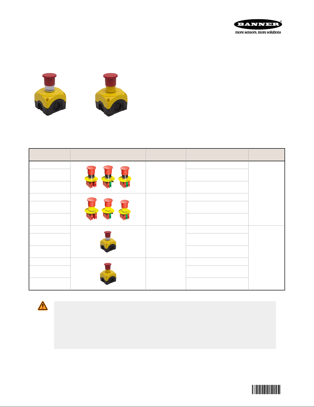
Figure 1. SSA-EBM-xxE Series
with Enclosure
Figure 2. SSA-EBP-xxE Series
with Enclosure
(positive) opening operation per IEC 60947-5-1
Models
SSA-EBM-02L
SSA-EBM-11L
SSA-EBM-12L
SSA-EBP-02L
SSA-EBP-11L
SSA-EBP-12L
SSA-EBM-02E
SSA-EBM-11E
SSA-EBM-12E
SSA-EBP-02E
SSA-EBP-11E
SSA-EBP-12E
Button Base
Material
Metal
Plastic
Metal
Plastic
Contacts
2 normally closed
1 normally closed and 1
normally open
2 normally closed and 1
normally open
2 normally closed
1 normally closed and 1
normally open
2 normally closed and 1
normally open
2 normally closed
1 normally closed and 1
normally open
2 normally closed and 1
normally open
2 normally closed
1 normally closed and 1
normally open
2 normally closed and 1
normally open
Enclosure
Included
No
Yes
WARNING: Not a Safeguarding Device
An Emergency Stop Device is not considered a safeguarding device because it requires an
overt action by an individual to stop machine motion or hazards.
A safeguarding device limits or eliminates an individual's exposure to a hazard without action by the
individual or others. Because an individual must actuate the device for it to function, these devices do
not fit the definition of a safeguarding device and cannot be substituted for required safeguarding. Refer
to the relevant standards to determine those requirements.
Original Document
111880 Rev. A
12 February 2014
Page 2
SSA-EB Series Emergency Stop Buttons
Important -- Read This First!
The user is responsible for satisfying all local, state, and national laws, rules, codes, and regulations relating to
the use of this product and its application. Banner Engineering Corp. has made every effort to provide complete
application, installation, operation, and maintenance instructions. Please direct any questions regarding the use or
installation of this product to the factory applications department at the telephone numbers or address found at http://
www.bannerengineering.com.
The user is responsible for making sure that all machine operators, maintenance personnel, electricians, and
supervisors are thoroughly familiar with and understand all instructions regarding the installation, maintenance, and use of
this product, and with the machinery it controls. The user and any personnel involved with the installation and use of this
product must be thoroughly familiar with all applicable standards, some of which are listed within the specifications.
Banner Engineering Corp. makes no claim regarding a specific recommendation of any organization, the accuracy or
effectiveness of any information provided, or the appropriateness of the provided information for a specific application.
Applicable U.S. Standards Applicable International Standards
ANSI B11 Standards for Machine Tools Safety
Contact: Safety Director, AMT – The Association for Manufacturing
Technology, 7901 Westpark Drive, McLean, VA 22102, Tel.:
703-893-2900
ANSI NFPA 79 Electrical Standard for Industrial Machinery
Contact: National Fire Protection Association, 1 Batterymarch
Park, P.O. Box 9101, Quincy, MA 02269-9101, Tel.: 800-344-3555
ANSI/RIA R15.06 Safety Requirements for Industrial Robots and
Robot Systems
Contact: Robotic Industries Association, 900 Victors Way, P.O. Box
3724, Ann Arbor, MI 48106, Tel.: 734-994-6088
ISO 12100-1 & -2 (EN 292-1 & -2) Safety of Machinery – Basic
Concepts, General Principles for Design
IEC 60204-1 Electrical Equipment of Machines Part 1: General
Requirements
ISO 13849-1 (EN 954-1) Safety-Related Parts of Control Systems
ISO 13856-1 (EN1760-1), Safety of Machinery – Pressure-
Sensitive Protective Devices
Contact: Global Engineering Documents, 15 Inverness Way East,
Englewood, CO 80112-5704, Tel.: 800-854- 7179
Overview
Models SSA-EB series are metal or plastic “mushroom-style” mechanical emergency stop buttons, available with or without
a compact enclosure housing, to provide emergency stop actuation. When the button is armed, the switch’s normally
closed contacts are closed and its normally open contacts, if present, are open. When the button is pushed, the switch’s
normally closed contacts open and its normally open contacts close. The contacts remain in this condition until the push
button is manually rearmed. To manually rearm, twist the push button.
These emergency stop buttons are not safeguarding devices. They do not automatically protect personnel from injury.
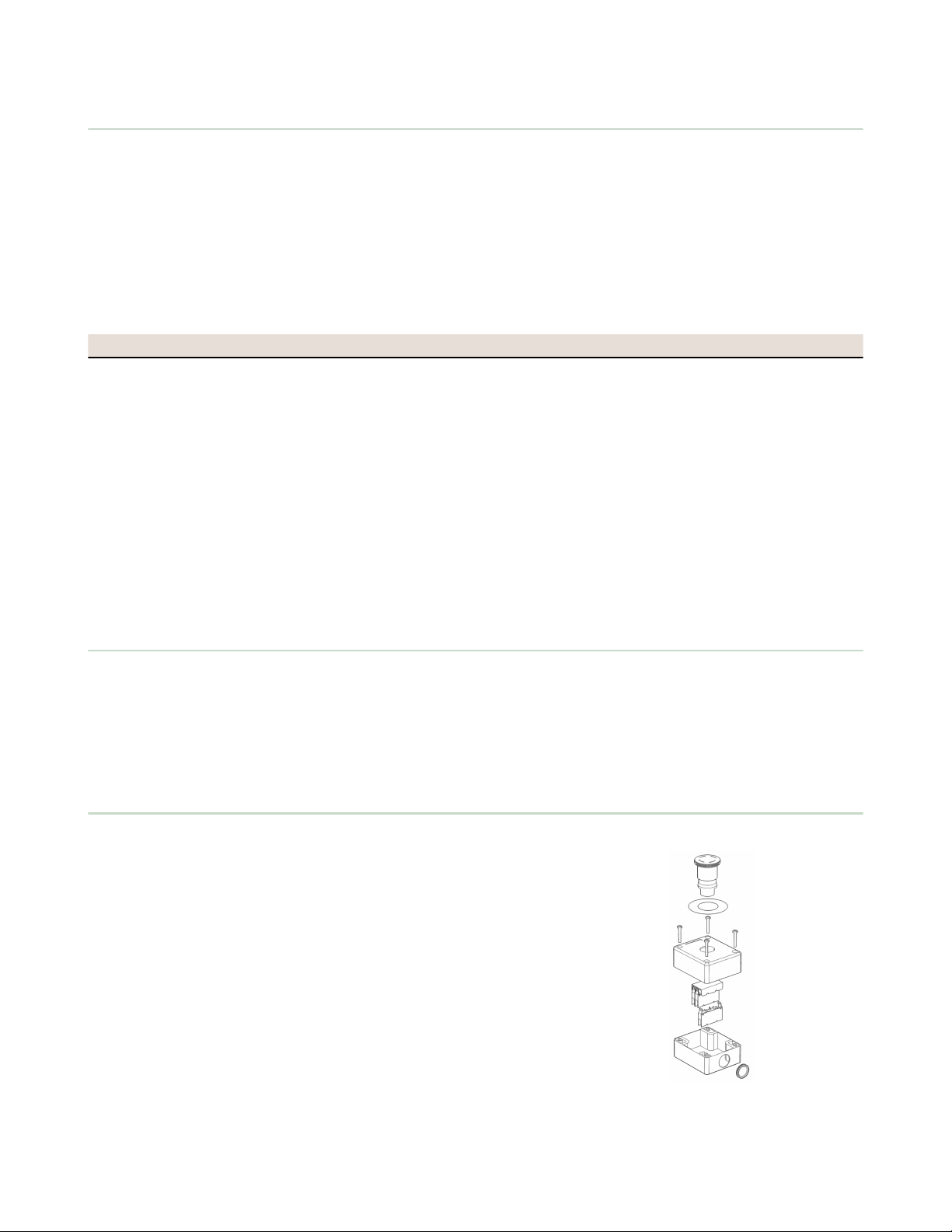
Installation
Mechanical Installation
1. Metal models: Latch the push button onto the mounting adapter
by rotating it.
2. All Models: Attach the mounting adapter to the mounting surface
using the incorporated screws. (Tmax = 7.14 in-lb/0.8 Nm).
Snap the auxiliary contacts onto the mounting adapter. Use the
disc label with legend at every switch per appropriate standards
3. Mount the E-Stop button on a rigid surface that is easily
accessible and visible to operators and other personnel. Refer to
appropriate standards for recommendations on number and
placement.
Electrical Installation
To access the wiring chamber, remove four screws and the cover.
Conduit mounting via removable rubber plug or knockout.
Figure 3. Assembly
2 www.bannerengineering.com - tel: 763-544-3164 P/N 111880 Rev. A
Page 3

SSA-EB Series Emergency Stop Buttons
Maintenance
At machine set up, a Designated Person
1
should test each emergency stop push button for proper machine shutdown
response.
The Designated Person should check the emergency stop buttons for proper operation, physical damage, button looseness,
and excessive environmental contamination. This should take place on a periodic schedule determined by the user, based
on the severity of the operating environment and the frequency of switch actuations
Adjust, repair, or replace components as needed. If inspection reveals contamination on the switch, thoroughly clean the
switch and eliminate the cause of the contamination. Replace the switch and/or appropriate components when any parts or
assemblies are damaged, broken, deformed, or badly worn; or if the electrical/mechanical specifications (for the
environment and operating conditions) have been exceeded.
Always test the control system for proper functioning under machine control conditions after performing maintenance,
replacing the emergency stop device, or replacing any component of the device.
Replacement Parts
8-LP2T-B6644
• 22.5 mm plastic button (mounting
adapter sold separately)
• Twist to release, mechanical latching
ISO 13850 (EN 418) compliant
• Diameter 40 mm (without mounting
adapter)
8-LM2T-B6644
• 22.5 mm metal button (mounting
adapter sold separately)
• Twist to release, mechanical latching
ISO 13850 (EN 418) compliant
• Diameter 40 mm (without mounting
adapter).
8-LM2T-C01
• Normally closed (N.C.) positively
driven contact element
• Direct (positive) opening operation
per IEC/EN 60947-5-1
8-LM2T-C10
Normally open (N.O.) auxiliary contact
element
8-LM2T-AU115
• 60 mm diameter
8-LM2T-AU120
Metal mounting adapter for metal button
LPZP1A5
• Compact size - 70mm x 70mm x 56mm (2.7” x 2.7” x 2.2”)
• One 22mm hole (with key way) for installation of emergency stop palm/push button
• Maximum of three contact blocks
• Polycarbonate construction
• Wire entry via three sides (M16, M20 or M25) or the bottom (M16)
• Environmental rating: IP66, IP67 and IP69K (with proper installation and rated button)
• Mounting hole location (x4) - 45mm x 58mm
1
A Designated Person is identified in writing by the employer as being appropriately trained to perform a specified checkout procedure. A Qualified Person
possesses a recognized degree or certificate or has extensive knowledge, training, and experience to solve problems relating to the emergency stop
installation (reference ANSI B30.2).
P/N 111880 Rev. A www.bannerengineering.com - tel: 763-544-3164 3
• Non-adhesive plastic legend with
“Emergency Stop” inscription
Page 4

39.9 mm dia
[1.57”]
56 mm
[2.2”]
70 mm
[2.76”]
104.9 mm
[4.13”]
58 mm
[2.28”]
45 mm
[1.77”]
4.3 mm dia
[0.1693”]
70 mm
[2.76”]
40
[1.6"]
10
[0.4"]
50
[1.97"]
43
[1.7"]
23
[0.9"]
1-6 Max
[0.04 - 0.24"]
ADD-ON
Elements
SSA-EB Series Emergency Stop Buttons
Specifications
Mechanical Life
300,000 operations
Operating Force
0.8 kg
Environmental rating
IP65; NEMA 4, 13
Operating Temperature
–25 °C to 60 °C (–13 °F to 140 °F)
European Rating
Utilization categories: AC15 and DC13
Ui = 690 V ac
Ith = 10 A
UL designation = A 600 Q600
Mechanical Life
1,000,000 operations
Connections
(1 or 2) 12 AWG (2.5 mm²) maximum wire size
Construction
Polyamide and polycarbonate
Emergency Stop Push Button
Mounting Adapter
Plastic button: The adapter is fixed to the mounting surface using
incorporated screws (Tmax = 0.6 Nm)
Metal button: The adapter is fixed to the mounting surface using
incorporated screws (Tmax = 0.8 Nm)
Construction
Plastic parts: Polyamide and polycarbonate
Metal parts: Aluminum and zinc alloy
Certifications
Compliant with EN/IEC 60497-1; -5-1
Contacts
Environmental rating
IP20
Operating Temperature
IP20
Operating Temperature
–25 °C to 60 °C (–13 °F to 140 °F)
Certifications
Compliant with EN/IEC 60497-1; -5-1
Dimensions
Figure 4. SSA-EBM-xxE and EBP-xxE Series E-Stop Buttons
Figure 5. SSA-EBM-xxL and EBP-xxL Series E-Stop Buttons
4 www.bannerengineering.com - tel: 763-544-3164 P/N 111880 Rev. A
Page 5

SSA-EB Series Emergency Stop Buttons
Banner Engineering Corp Limited Warranty
Banner Engineering Corp. warrants its products to be free from defects in material and workmanship for one year following
the date of shipment. Banner Engineering Corp. will repair or replace, free of charge, any product of its manufacture
which, at the time it is returned to the factory, is found to have been defective during the warranty period. This warranty
does not cover damage or liability for misuse, abuse, or the improper application or installation of the Banner product.
THIS LIMITED WARRANTY IS EXCLUSIVE AND IN LIEU OF ALL OTHER WARRANTIES WHETHER EXPRESS OR
IMPLIED (INCLUDING, WITHOUT LIMITATION, ANY WARRANTY OF MERCHANTABILITY OR FITNESS FOR A
PARTICULAR PURPOSE), AND WHETHER ARISING UNDER COURSE OF PERFORMANCE, COURSE OF DEALING OR
TRADE USAGE.
This Warranty is exclusive and limited to repair or, at the discretion of Banner Engineering Corp., replacement. IN NO
EVENT SHALL BANNER ENGINEERING CORP. BE LIABLE TO BUYER OR ANY OTHER PERSON OR ENTITY FOR
ANY EXTRA COSTS, EXPENSES, LOSSES, LOSS OF PROFITS, OR ANY INCIDENTAL, CONSEQUENTIAL OR
SPECIAL DAMAGES RESULTING FROM ANY PRODUCT DEFECT OR FROM THE USE OR INABILITY TO USE THE
PRODUCT, WHETHER ARISING IN CONTRACT OR WARRANTY, STATUTE, TORT, STRICT LIABILITY,
NEGLIGENCE, OR OTHERWISE.
Banner Engineering Corp. reserves the right to change, modify or improve the design of the product without assuming any
obligations or liabilities relating to any product previously manufactured by Banner Engineering Corp.
www.bannerengineering.com - tel: 763-544-3164
 Loading...