

Page 1
®
MAXI-BEAM
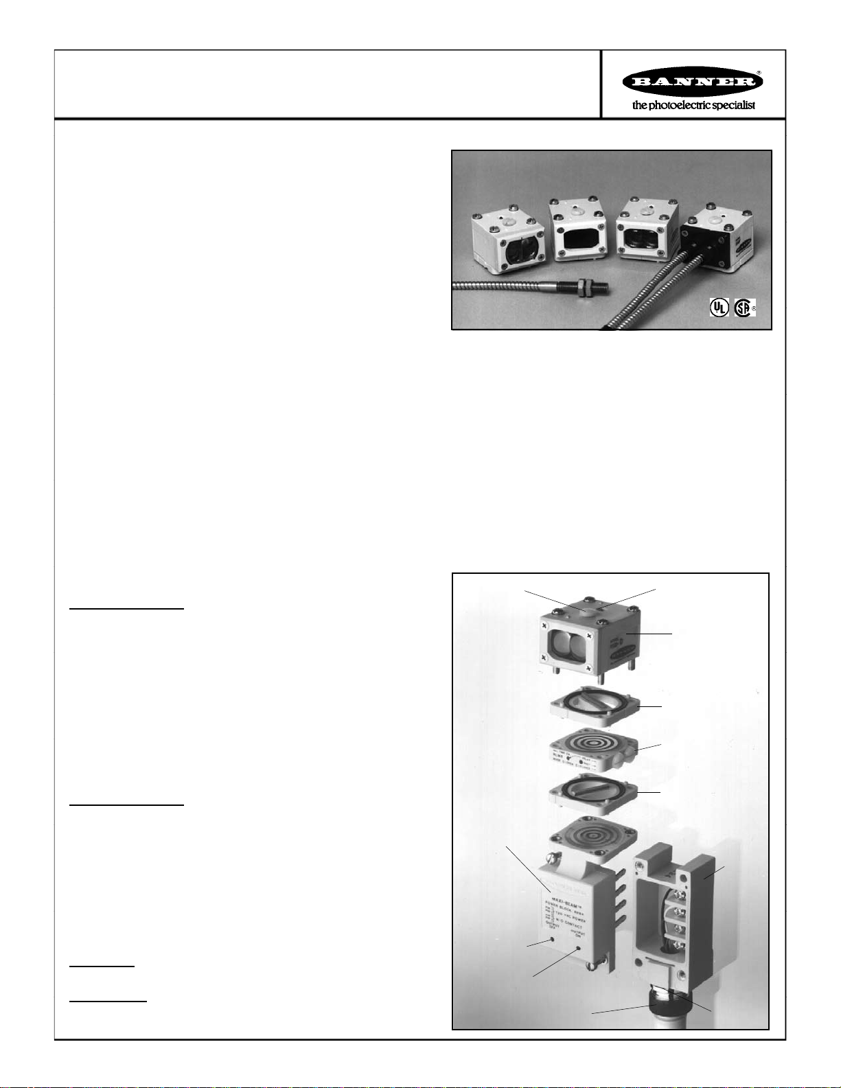
Banner MAXI-BEAM® sensors are highly versatile, self-contained, modularized photoelectric sensing controls that are ideally suited to industrial en-vironments. The basic MAXI-BEAM is an ON/OFF switch consisting of three
modules (sensor head, power block, and wiring base) and a unique, patented,
rotatable "programming ring" that enables you to program your choice of
"light" or "dark" operate mode, sensing range, and response time.
MAXI-BEAM sensor heads have an easily-accessible multi-turn SENSITIVITY control for precise adjustment of system gain. Interchangeable
sensor heads are rotatable in 90-degree increments and are available in
retroreective, diffuse, opposed, convergent, xed-eld proximity, and
beroptic sensing modes. Each sensor head also includes Banner's exclusive,
patented AID™ circuit (Alignment Indicating Device*), which features
an LED alignment indicator that lights whenever the sensor "sees" its own
modulated light source, and pulses at a rate proportional to the strength of
the received light signal.
A wide selection of MAXI-BEAM power block modules is available to
interface the sensor head to the circuit to be controlled. The plug-in design
of the wiring base enables easy exchange of the entire sensing electronics
without disturbing eld wiring.
Optional customer-installable logic modules easily convert the basic ON/OFF
MAXI-BEAM into either a one-shot or delay logic function control, with
several programmable timing ranges for each function.
MAXI-BEAM sensors are ruggedly constructed of molded VALOX
NEMA standards 1, 3, 4, 12, and 13, and have interchangeable molded
acrylic lenses. Modules simply snap and bolt together, with no interwiring necessary. Module interfaces are o-ring and quad-ring sealed for the
ultimate in dust, dirt, and moisture resistance.
To order a MAXI-BEAM, follow these steps:
1) Select a sensor head module,
2) Select a power block module,
3) Select a wiring base,
4) Select a logic module (if needed),
5) Select accessories as needed (see Banner product catalog).
Sensor Head Modules (described in this data sheet, P/N 03416)
RSBE & RSBR
300'
RSBESR & RSBRSR
RSBLV retroreective mode range to 30'
RSBLVAG
RSBD
long range diffuse proximity mode range to 5'
RSBDSR short-range diffuse proximity mode range to 30"
RSBCV visible red convergent mode, focus at: 1.5"
RSBC infrared convergent mode, focus at: 1.5"
RSBF infrared ber optic; for glass bers
RSBFV visible red ber optic; for glass bers
RSBEF & RSBRF
RSBFP
RSBFF50, RSBFF100
mm
Power Block Modules (see data sheet P/N 03418)
RPBT
10-30V dc; one sinking and one sourcing solid-state output
RPBT-1
RPBTLM
RPBA
105-130V ac (50/60Hz); SPST solid-state output
RPBA-1
R2PBA
RPBB
210-250V ac (50/60Hz); SPST solid-state output
RPBB-1
R2PBB
RPBU
RPBR
12-250V ac (50/60Hz) or 12-30V dc; SPST E/M relay output
RPBR2
Wiring Base (see data sheet P/N 03418)
RWB4
4-terminal wiring base for all models (except RPBTLM)
Logic Modules (see data sheet P/N 03417)
RLM5
ON/OFF delay (both functions adjustable up to 15 seconds)
RLM8
DELAYED ONE-SHOT (delay and pulse adjustable up to
15 seconds)
Printed in U
opposed mode r an g e t o
opposed mode (short range; narrow beam) range to 15'
retroreective mode (anti-glare lter) range to 15'
infrared ber optic opposed mode; for glass bers
visible red ber optic; for plastic bers
xed-eld proximity; sharp far-limit cutoff at 50 or 100
10-30V dc; for use with RSBE, ESR, EF emitters (no output circuit)
10-30V dc low-prole power block (requires no RWB4 wiring base)
105-130V ac (50/60Hz); for use with emitter (no output circuit)
2-wire operation; 105-130V ac (50/60Hz); SPST solid-state output
210-250V ac (50/60Hz); use with emitter (no output circuit)
2-wire operation; 210-250V ac (50/60Hz); SPST solid-state output
12-250V ac or 12-30V dc; SPST solid-state output (ac or dc)
12-250V ac (50/60Hz) or 12-30V dc; SPDT E/M relay output
Sensor Heads
Some MAXI-BEAM sensor heads: models RSBC, RSBDSR,
RSBLV, and RSBF (shown with bifurcated ber optic assembly
attached).
General Specications
Construction: Reinforced molded VALOX
lenses, o-ring and quad-ring gasketed components. Electronic components
are fully epoxy encapsulated. NEMA 1, 3, 4, 12, and 13.
Operating Temperature: -40 to +70°C (-40 to +158°F).
Sensitivity Adjustment: Easily accessible, located on top of the sensor
head beneath a watertight gasketed screw-cover. 15-turn clutched control;
rotate clockwise to increase sensitivity.
®
to
Alignment Indicator: Red LED on top of sensor head. Banner's ex-
clusive AID™ circuit (*US patent no. 4356393) lights the LED whenever
the sensor sees its own modulated light source, and pulses the LED at a
rate proportional to the strength of the received light signal.
False Pulse Suppression on Power-up: 100ms delay on power-
up.
Response Time and Repeatability: Specications to follow in indi-
vidual product descriptions are independent of signal strength.
VALOX® is a registered trademark of General Electric Co.
Sensitivity
Control
Power Block
Output OFF
LED
Output ON
LED
Quick Disconnect (optional)
®
housing, molded acrylic
LED/AID™
Indicator
Rotatable
Sensor Head
Programming
Ring
Optional
Logic Module
Programming
Ring for Logic
RWB4
Wi ri n g
Base
Conduit
Entrance
P/N 03416 Rev. )
Page 2
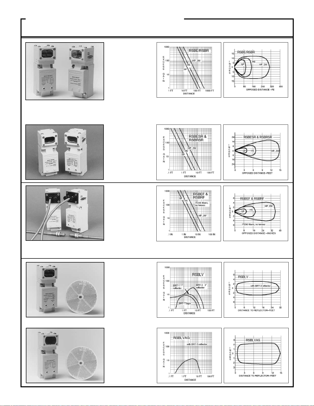
MAXI-BEAM Sensor Heads
Sensing Mode Models
RSBE & RSBR
Range: 300 feet (90 m) in
"HP" (high power) and 2W
(2 wire) modes
Beam: infrared, 880nm;
visible red tracer beam
Effective Beam: 0.5" dia.
Response:
HP, 2W mode: 10ms on/
5 off
HS mode: 1ms on/0.5 off
SP mode: 0.3ms on/off
Repeatability: HP, 2W=
1.4ms; HS = 0.1ms;
OPPOSED Mode
SP = 0.04ms
RSBESR &
RSBRSR
Range: 15 feet (4,5m) in
"HP" (high power) and 2W
(2 wire) modes
Beam: infrared, 880nm
Response:
HP, 2W modes:
10ms on/5 off
HS mode: 1ms on/0.5 off
SP mode: 0.3ms on/off
Repeatability: HP, 2W=
1.4ms; HS = 0.1ms;
SP = 0.04ms
Excess Gain
MAXI-BEAM emitters have a visible red "tracer beam". This beam is non-active,
and is used as a means of visual alignment during installation. A retroreector
temporarily attached to the receiver lens provides an effective target for the tracer
beam during alignment. The narrow beam of the RSBESR/RSBRSR pair is ideal
for sensing small parts (effective beam diameter is 0.14 inch).
Beam Pattern
OPPOSED FIBER OPTIC
Mode
(glass bers)
RETROREFLECTIVE Mode
RSBEF &
RSBRF
Range: see excess gain
curves
Beam: infrared, 880nm.
Response:
HP, 2W modes: 10ms
HS mode: 1ms
SP mode: 0.3ms on/off
Repeatability: HP, 2W=
3.3ms; HS = 0.3ms;
SP = 0.1ms
RSBLV
Range: 6 inches to 30 feet
(9 m) in all program modes
Beam: visible red, 650nm
Response:
HP, 2W, SP modes: 4ms
HS mode: 1ms
Repeatability:
HP, 2W, SP = 1.3ms;
HS = 0.3ms
RSBLVAG
(anti-glare lter)
Range: 1 to 15 feet (4,5 m)
in all program modes
Beam: visible red, 650nm;
with polarizing lter
Response:
HP, 2W, SP modes: 4ms
HS mode: 1ms
Repeatability: HP, 2W,
SP = 1.3ms; HS = 0.3ms
This sensor pair is designed for opposed mode operation using Banner glass ber
optics. Maximum range (HP mode) using L9 lenses is 12 feet. Maximum range
using L16F lenses is 50 feet.
2
Page 3

MAXI-BEAM Sensor Heads
1000
100
10
1
0.1 mm
1 mm
10 mm
100 mm
MAXI-BEAM Fixed-field
Sensor Heads
E
X
C
E
S
S
G
A
I
N
DISTANCE
100 mm
50 mm
5
(Range based on 90% reflectance
white test card)
Sensing Mode Models
RSBD
Range: 5 feet (1,5 m) in
HP and 2W modes
Beam: infrared, 880nm
Response:
HP, 2W modes: 10ms
HS mode: 1ms
SP mode: 0.3ms
Repeatability: HP, 2W=
3.3ms; HS = 0.3ms;
SP = 0.1ms
DIFFUSE Mode
CONVERGENT Mode
RSBDSR
(short range)
Range: 30 inches (76cm)
in HP and 2W modes
Beam: infrared, 880nm
Response:
HP, 2W modes: 10ms
HS mode: 1ms
SP mode: 0.3ms
Repeatability: HP, 2W=
3.3ms; HS =0.3ms;
SP =0.1ms
RSBC
Focus at 1.5 in. (38mm)
Beam: infrared, 940nm
Response:
HP, 2W modes: 10ms
HS mode: 1ms
SP mode: 0.3ms
Repeatability:
HP, 2W= 3.3ms;
HS = 0.3ms;
SP= 0.1ms
RSBCV
Focus at 1.5 in. (38mm);
performance equal in all
program modes.
Beam: visible red, 650nm.
Response:
HP, 2W, SP modes: 4ms
HS mode: 1ms
Repeatability:
HP, 2W, SP= 1.3ms;
HS = 0.3ms
Excess Gain
Powerful infrared beam reliably senses objects of low reectivity. Ideal for counting the ow of radiused products at a xed distance from the sensor.
Beam Pattern
Powerful visible red beam with precise .06" diameter sensing spot. Useful in many high-contrast color registration applications.
3
FIXED-FIELD Mode
RSBFF models
Far limit cutoff at:
50mm (model RSBFF50) or
100mm (model RSBFF100)
Beam:
infrared, 880nm.
Response:
HP mode: 10ms
Repeatability:
HP mode: 3.3ms
Fixed-eld sensor heads have an emitter element and two differently-aimed
receiver elements. This creates a
high-gain sensing eld able to detect
objects of low reectivity, and a sharp
far-limit sensing cutoff of 50mm (2
inches) or 100mm (4 inches) which
ignores backgrounds beyond cutoff.
These sensors are ideal for detecting a
part or surface that is only a fraction of
an inch in front of another surface.
RSBFFs may not be used with 2-wire
power blocks.
Page 4

MAXI-BEAM Sensor Heads
OBJECT
OBJECT
RETROREFLECTOR
OBJECT
OBJECT
OBJECT
Sensing Mode Models
FIBER OPTIC Mode
(glass bers)
OPPOSED
MODE
RETRO
MODE
RSBF
Range: see excess gain
curves
Beam: infrared, 880nm
Response:
HP, 2W modes: 10ms
HS mode: 1ms
SP mode: 0.3ms
Repeatability:
HP, 2W= 3.3ms;
HS = 0.3ms;
SP = 0.1ms
NOTE: if the
retroreective sensing
mode is used in
conjunction with the
HP or 2W program
mode, the GAIN control
must be reduced from
the factory setting in
order to avoid optical
feedback from the lens
assembly.
Excess Gain
Beam Pattern
DIFFUSE
MODE
FIBER OPTIC Mode
OPPOSED
MODE
For information on the
complete line of Banner
glass ber optics, see
Banner product catalog.
RSBFP
Range: see excess gain
curves
Beam: visible red, 650nm.
Response:
HS mode only, 1ms on/off
Repeatability:
HS = 0.3ms
The model RSBFP will
function only when
programmed for the "HS"
response mode.
The model RSBFP will
not operate with 2-wire
power blocks (models
R2PBA and R2PBB).
Model RSBFP is a visible-light sensor head designed for use with plastic ber
optics. It is compatible with all standard Banner plastic ber optic assemblies
(see Banner product catalog). In order to function properly, the RSBFP must be
programmed for the "HS" response mode. The RSBFP is not for use with glass
ber optics (instead use model RSBF or RSBFV).
DIFFUSE
MODE
4
For information on the
complete line of Banner
plastic ber optics, see
Banner product catalog.
Page 5

MAXI-BEAM Sensor Heads
OBJECT
OBJECT
RETROREFLECTOR
OBJECT
Sensing Mode Models Beam Pattern
Excess Gain
RSBFV
Range: see excess gain
curves
Beam: visible red, 650nm.
Response:
HS mode only, 1ms on/o
Repeatability:
HS = 0.3ms
The model RSBFV will
function only when
FIBER OPTIC Mode
(glass bers)
OPPOSED
MODE
RETRO
MODE
DIFFUSE
MODE
programmed for the "HS"
response mode.
The model RSBFV will
not operate with 2-wire
power blocks (models
R2PBA and R2PBB).
Model RSBFV is a
visible-light sensor head
designed for use with
glass ber optics. It is
compatible with all standard Banner glass ber
optic assemblies (see
Banner product catalog).
In order to function
properly, the RSBFV
must be programmed
for the "HS" response
mode. The RSBFV is
not for use with plastic
ber optics (instead use
RSBFP).
Programming the MAXI-BEAM Sensor Head
MAXI-BEAM sensor heads may be programmed for sensor response time (and range) and for
LIGHT/DARK operate. Each sensor head is supplied with a programming ring which attaches
below the the sensor head by a system of pegs. There are four programming notches around
the perimeter of the ring. To program the sensor head, simply nd the notch which will line
up with the desired program combination (see diagram, right). NOTE: the programming ring
may have to be turned upside-down in order to line up the notch with the program. If LIGHT
.noitisnart thgil-ot-krad a no ezigrene lliw tuptuo MAEB-IXAM eht ,detceles si ETAREPO
If DARK OPERATE is selected, the MAXI BEAM output will energize on a light-to-dark
transition. In the illustration, the MAXI-BEAM is set for high speed (HS) operation in the
LIGHT OPERATE output state. See the information about each individual sensor head for
the response time and range associated with each setting (HP, 2W, HS, SP). NOTE: when
programming the
for the receiver. EXCEPTION: if the receiver is programmed for the 2-wire (2W) mode, select
high power (HP) on the emitter.
RSBE, RSBSER, or RSBEF emitter, select the mode which is programmed
WARNING MAXI-BEAM photoelectric presence sensors do NOT include the self-checking redundant circuitry necessary
to allow their use in personnel safety applications. A sensor failure or malfunction can result in either an energized or de-energized
sensor output condition.
Never use these products as sensing devices for personnel protection. Their use as safety devices may create an unsafe condition
which could lead to serious injury or death.
Only MACHINE- GUARD and PERIMETER- GUARD Systems, and other systems so designated, are designed to meet OSHA and ANSI
machine safety standards for point- of -operation guarding devices. Nother Banner sensors or controls are designed to meet these
standards, and they must NOT be used as sensing devices for personnel protection.
5
Page 6

Dimension Drawing
Functional Schematic, MAXI-BEAM Sensor Heads
Banner Engineering Corp Limited
Warranty
Banner Engineering Corp. warrants its products to be free
from defects in material and workmanship for one year
following the date of shipment. Banner Engineering Corp.
will repair or replace, free of charge, any product of its
manufacture which, at the time it is returned to the factory,
is found to have been defective during the warranty period.
This warranty does not cover damage or liability for misuse,
abuse, or the improper application or installation of the
Banner product.
THIS LIMITED WARRANTY IS EXCLUSIVE AND IN
LIEU OF ALL OTHER WARRANTIES WHETHER
EXPRESS OR IMPLIED (INCLUDING, WITHOUT
LIMITATION, ANY WARRANTY OF MERCHANTABILITY
OR FITNESS FOR A PARTICULAR PURPOSE), AND
WHETHER ARISING UNDER COURSE OF
PERFORMANCE, COURSE OF DEALING OR TRADE
USAGE.
This Warranty is exclusive and limited to repair or, at the
discretion of Banner Engineering Corp., replacement. IN
NO EVENT SHALL BANNER ENGINEERING CORP. BE
LIABLE TO BUYER OR ANY OTHER PERSON OR
ENTITY FOR ANY EXTRA COSTS, EXPENSES,
LOSSES, LOSS OF PROFITS, OR ANY INCIDENTAL,
CONSEQUENTIAL OR SPECIAL DAMAGES
RESULTING FROM ANY PRODUCT DEFECT OR
FROM THE USE OR INABILITY TO USE THE PRODUCT,
WHETHER ARISING IN CONTRACT OR WARRANTY,
STATUTE, TORT, STRICT LIABILITY, NEGLIGENCE,
OR OTHERWISE.
Banner Engineering Corp. reserves the right to change,
modify or improve the design of the product without
assuming any obligations or liabilities relating to any
product previously manufactured by
Banner Engineering Corp.
Composite Functional Schematic, MAXI-BEAM Sensors
RWB4
Banner Engineering Corp. 9714 Tenth Ave. No. Minneapolis, MN 55441 Telephone: (612)544-3164 FAX (applications): (612)544-3573
 Loading...