

Page 1
MAXI-AMP® System
Stand-alone sensor contr ol modules
Product
Line
Specifications
Versatile, cost-effective sensor control modules: models
•
available for use with most Banner photoelectric sensors
Power supply, photoelectric amplifier (CD and CM
•
Series), programmable timing logic (CD5, CM5, and CL5
models), and output relay in a single, compact plug-in
module
•
CD5, CL5, and CM5 models include 12 selectable delay,
pulse, and latch timing logic functions
(single or dual functions)
•
All models have 5-amp SPDT electromechanical relay
output (solid-state switch optional); some models offer
additional solid-state dc switch (see table, page 2)
Printed in USA P/N 32882
Page 2
™
MAXI-AMP System
Stand-alone Sensor Control Modules
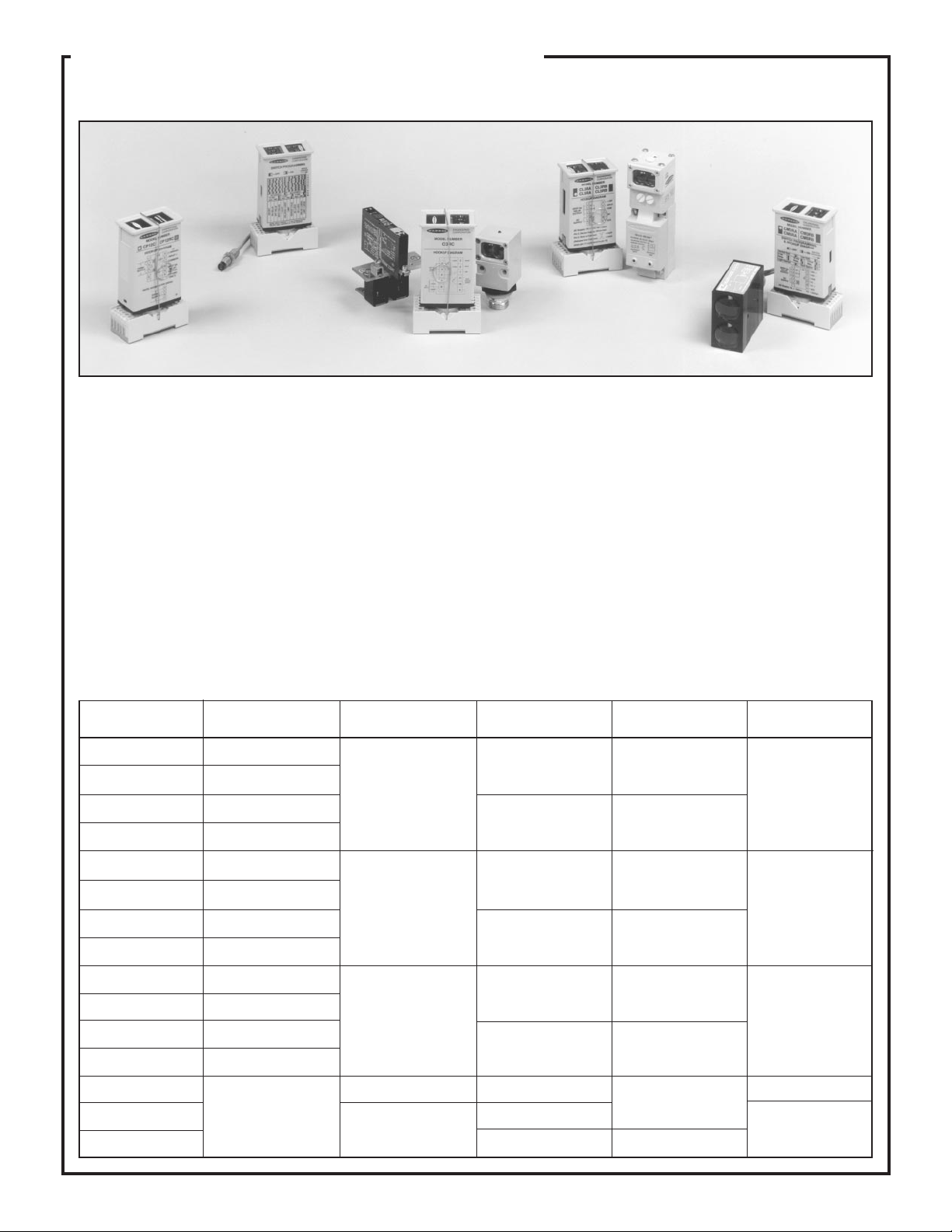
Banner MAXI-AMPs are the most versatile and cost-effective
sensor control modules available anywhere. MAXI-AMP system
modules combine power supply, photoelectric amplifier (CD and
CM series), programmable timing logic (CD5, CM5, and CL5
models), and output relay in a single, compact plug-in module. This
integrated stand-alone design saves both the expense of a separate
control chassis and a substantial amount of control panel space.
MAXI-AMP modules are powered directly by AC line voltage.
Models are available for either 120V ac or 220/240V ac operation.
CD Series MAXI-AMP modules accept input signals from SP12
Series preamplified remote sensors. The preamplified design of
this system produces exceptionally high noise immunity.
CM Series MAXI-AMPs are designed to work with the popular line
of Banner high-performance modulated remote sensors. The CR
Series is a low-gain version of the CM Series, and is designed for
use with the SP100 Series miniature remote sensors.
CL Series MAXI-AMP modules accept input signals from any
MODULE
MODEL
CD3RA
CD3RB
CD5RA
CD5RB
CM3RA
CM3RB
CM5RA
CM5RB
CL3RA
CL3RB
CL5RA
CL5RB
CI3RC
CP12RC
CP12C
SUPPLY
VOLTAGE
105 to 130V ac, or
12 to 28V dc
210 to 250V ac, or
12 to 28V dc
105 to 130V ac, or
12 to 28V dc
210 to 250V ac, or
12 to 28V dc
105 to 130V ac, or
12 to 28V dc
210 to 250V ac, or
12 to 28V dc
105 to 130V ac, or
12 to 28V dc
210 to 250V ac, or
12 to 28V dc
105 to 130V ac, or
12 to 28V dc
210 to 250V ac, or
12 to 28V dc
105 to 130V ac, or
12 to 28V dc
210 to 250V ac, or
12 to 28V dc
105 to 130V ac
or
210 to 250V ac
USED WITH
(INPUT)
CD Series MAXI-AMP
modules contain a
modulated photoelectric
amplifier for use with
SP12 Series preamplified
remote sensors
(pp. 7-9).
CM Series MAXI-AMP
modules contain a
modulated photoelectric
amplifier for use with the
full complement of
Banner high performance modulated remote
sensors (pp. 13-17).
CL Series modules
accept signals from any
Banner DC sensor or
module with NPN
(current sinking) output.
SMI912 series intrinsically
safe sensors.
Supplies 400mA to power
MAXI-AMP modules
and/or other 10-30V dc
sensing devices.
Banner dc module and most dc self-contained sensors.
CI Series MAXI-AMPs provide the power supply, current ampli-
fier, and output device for an SMI912 Series intrinsically safe
sensor. CI Series modules are covered in data sheet P/N 03461.
CD5, CM5, and CL5 models include a multi-function timing logic
circuit, which is easily programmed for twelve of the most popular
and useful delay, pulse, and latch functions. MAXI-AMPs offer the
choice of either single or dual timing functions in the same module.
MAXI-AMPs offer a 5-amp SPDT electromechanical relay output.
Solid-state switches are available as an option. CD3, CM3 and CL3
models offer an additional solid state dc switch.
®
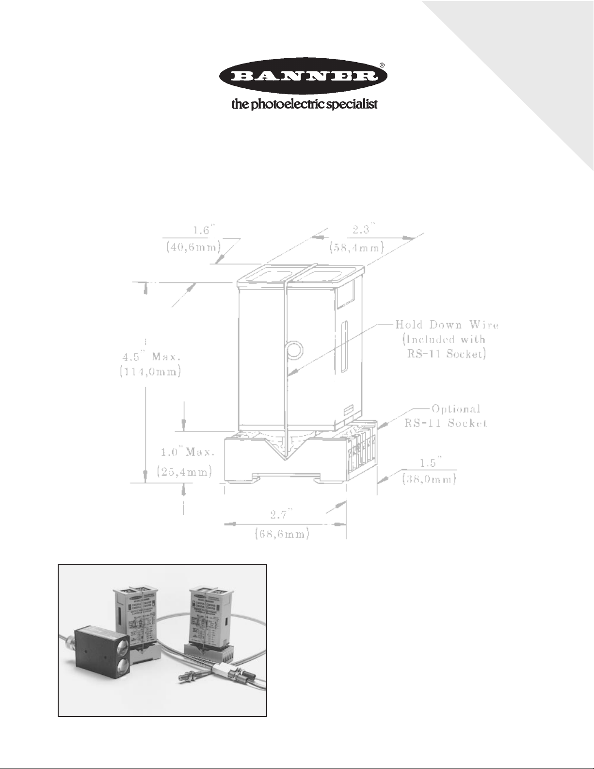
MAXI-AMPs are contained in a tough NORYL
housing which
measures a compact 1.6 x 2.3 x 4". Electrical connections are made
via any standard 11-pole round-pin relay socket (model RS-11).
All MAXI-AMP system modules (except model CI3RC) are CSA
certified and UL recognized.
OUTPUT
CONFIGURATION
SPDT electromechanical relay, plus NPN
transistor solid-state
switch
SPDT
electromechanical relay
SPDT electromechanical relay, plus NPN
transistor solid-state
switch
SPDT
electromechanical relay
SPDT electromechanical relay, plus NPN
transistor solid-state
switch
SPDT
electromechanical relay
SPDT E/M relay, isolated solid state DC switch
SPDT electromechanical relay
No output device
(power supply only)
LOGIC
FUNCTION(S)
ON/OFF
(output follows input)
Selection of 12 programmable functions
including delay, pulse,
limit, cycle, and latch
ON/OFF
(output follows input)
Selection of 12 programmable functions
including delay, pulse,
limit, cycle, and latch
ON/OFF
(output follows input)
Selection of 12 programmable functions
including delay, pulse,
limit, cycle, and latch
ON/OFF
(output follows input)
No logic function
(power supply only)
REFER TO
PAGES ...
See pages
3-9
See pages
10-17
See pages
18-21
See data sheet 03461
See page 22
2
Page 3
™
MAXI-AMP CD Series
Programmable Modulated Amplifier and Control Modules
for use with SP12 Series Preamplified Remote Photoelectric Barrel Sensors
Modulated photoelectric amplifier, power supply,
•
output relay, and versatile timing logic (CD5 models)
in one compact, stand-alone package
120 or 240V ac or 12-28V dc operation; requires only
•
the addition of a Banner SP12 preamplified opposed
mode sensor pair to create a powerful sensing system
CD5 models are easily programmed for any of twelve
•
delay, one-shot, and latch functions (either single or
dual timing); interrogation schemes are possible
using auxiliary input
Exceptionally high immunity to ambient light and
•
electrical noise; no false pulse on power-up
Rugged, 15-turn potentiometers for precise timing
•
and sensitivity adjustment; tough Noryl
Includes Banner's exclusive AID™ alignment system
•
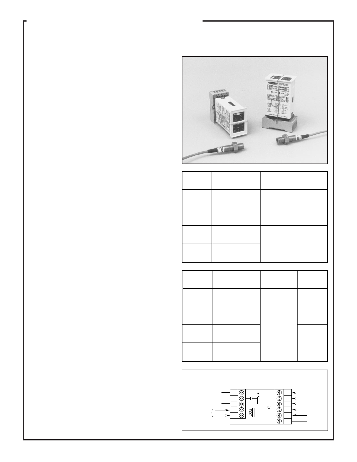
CD Series MAXI-AMP modules combine power supply, modulated
photoelectric amplifier, timing logic (in CD5 models) and output
switch in a single compact, cost-saving module. CD Series modules
work together with Banner SP12 Series preamplified remote sensors.
These sensors offer small size and high power, and are built to operate
in highly demanding sensing environments. Their preamplified design
gives them exceptionally high immunity to electrical noise (see page 7
for further information). MAXI-AMP modules themselves are also
ruggedly built for dependable industrial duty.
CD Series MAXI-AMP modules contain a state-of-the-art Banner
CMOS modulator/demodulator/amplifier circuit that offers high immunity to both ambient light and electrical interference plus reliable
sensor performance. All models have Banner's exclusive, patented
Alignment Indicating Device (AID™) system, which lights an LED
indicator whenever the receiver sees a "light" condition, and pulses the
LED at a rate proportional to the received light signal strength. MAXIAMP modules operate from a variety of voltages (see tables at right).
All CD Series modules are programmable for LIGHT or DARK operate. Module input response time may be set at either 1.5 or 15 milliseconds. The 15-millisecond response mode offers maximum sensing
power (excess gain) with SP12 Series sensors. CD Series modules also
feature selectable sensor modulation frequencies ("A" and "B"). This
makes it possible to operate two high-powered SP12 Series sensor pairs
using different modulation frequencies (at the same response time
setting) in close proximity to each other without optical crosstalk.
CD5 models include a versatile multi-function timing logic circuit that
is programmable for 12 popular and useful delay, one-shot, and latch
functions. Each timing function has a choice of three time ranges.
Timing and sensitivity adjustments use rugged 15-turn potentiometers
for very accurate settings. CD Series module circuit design prevents
false outputs on system power-up.
The output circuit for CD3A, 3B, 5A, and 5B modules consists of two
SPST solid-state switches: one for ac loads of up to 250V ac (3/4 amp),
and a second for dc loads of up to 30V dc (50 mA). Models CD5RA
and CD5RB have a 5-amp SPDT electromechanical relay. CD3RA and
CD3RB modules have a 5-amp SPDT electromechanical relay plus an
NPN transistor solid-state switch. For more information on output
circuit load capability, refer to the tables (right) and the Specifications
section on the next page.
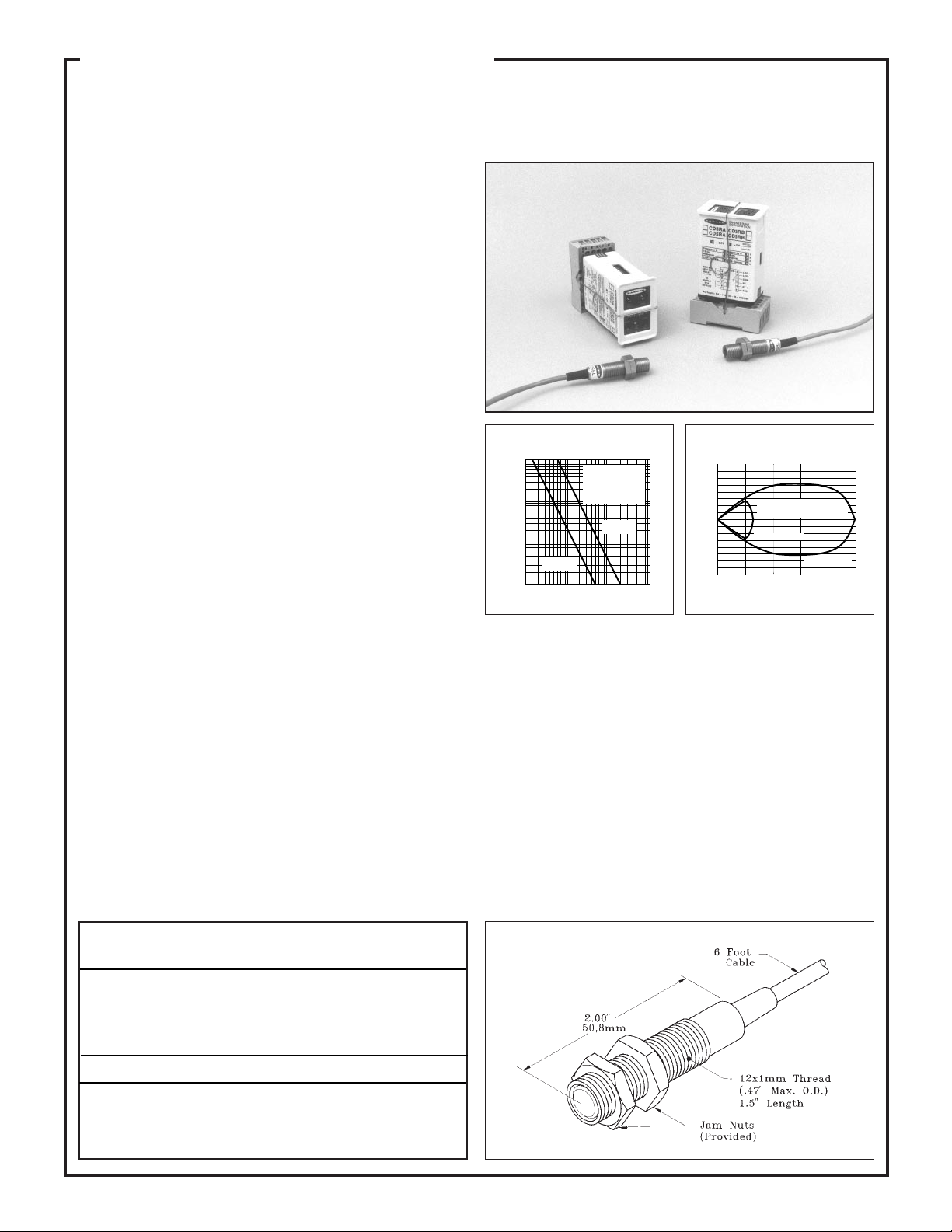
®
housing
MAXI-AMP™ CD Series amplifier and control modules are
designed to operate with SP12 Series
sensors (foreground, see page 7).
MODEL
CD3RA
CD3RB
CD5RA
CD5RB
MODEL
CD3A
CD3B
CD5A
CD5B
SUPPLY
VOLTAGE
105 to 130V ac, or
12 to 28V dc
210 to 250V ac, or
12 to 28V dc
105 to 130V ac, or
12 to 28V dc
210 to 250V ac, or
12 to 28V dc
SUPPLY
VOLTAGE
105 to 130V ac, or
12 to 28V dc
210 to 250V ac, or
12 to 28V dc
105 to 130V ac, or
12 to 28V dc
210 to 250V ac, or
12 to 28V dc
Generalized Hookup: models with solid-state output
Isolated
solid-state
contacts:
DC load
AC load
Load common
AC
Supply
4
5
6
7
8
CD3A
CD3B
CD5A
CD5B
SPDT electromechanical
relay, plus
NPN transistor
solid-state
switch
SPDT electromechanical
relay (5 amp
contact rating)
SPST solidstate contact
for switching
AC loads up
to 250V ac
and 3/4 amp,
plus solidstate contact
for switching
DC loads up
to 30V dc and
up to 50mA.
3
2
1
11
10
9
LOGICOUTPUT
ON/OFF
12
timing
functions
LOGICOUTPUT
ON/OFF
12
timing
functions
LED +
LED -
Common
PT PT +
Auxiliary
(see table)
3
Page 4
MAXI-AMP™ CD Series Modules Specifications
SUPPLY VOLTAGE: Models CD3(R)A, CD5(R)A: 105 to 130V ac,
50/60Hz (4 VA), or 12 to 28V dc* at 70mA. Models CD3(R)B,
CD5(R)B: 210 to 250V ac, 50/60Hz (4 VA), or 12 to 28V dc* at 70mA.
*NOTE: do not connect ac power when using external dc power.
OUTPUT CONFIGURATION:
CD3A, CD3B, CD5A, CD5B: Two solid-state SPST switches, one for
ac loads of up to 250V ac and up to 3/4 amp, the other for dc loads of up
to 30V dc and up to 50mA. CD3A and CD3B also have a logic level
current sinking NPN transistor switch at pin #9, maximum load 20mA
at 12V dc max.
CD3RA and CD3RB: SPDT electromechanical relay (see specifications, below) plus an NPN transistor solid-state logic-level dc switch (at
pin #9, maximum load 20mA at 12V dc max.).
CD5RA and CD5RB: SPDT electromechanical relay (specs below).
SPDT Electromechanical Relay Specifications:
CONTACT RATING: 250V ac max, 24V dc max, 5 amps max.
(resistive load), 1/10 H.P. at 240V ac. Install a transient suppressor
(MOV) across contacts that switch inductive loads.
CLOSURE TIME: 10 milliseconds max.
RELEASE TIME: 10 milliseconds max.
MAXIMUM SWITCHING SPEED: 20 operations/second
MECHANICAL LIFE: 20,000,000 operations
AMPLIFIER:
RESPONSE SPEED: Programmable for 1.5 or 15 milliseconds. NOTE:
use 15 millisecond setting for maximum sensor excess gain.
MODULATION FREQUENCY: selectable, "A" or "B".
SENSOR LEAD LENGTH: 100 feet (30 m) maximum, each sensor.
When splicing, use separate cable for emitter and receiver, or order
sensors with extended cable length.
SENSOR HOOKUP: One SP12 Series opposed mode sensor pair per
amplifier module. Additionally, one self-contained sensor may be
connected at pin #9 (CD5 models) to provide a RESET or INHIBIT
signal. +15V dc power for this one additional sensor is available at
module pin #3 (40mA maximum load).
TIMERS (CD5 models only):
Timing ranges: LOW range - 10 to 150 milliseconds
MIDDLE range - 0.1 to 1.5 seconds
HIGH range - 1 to 15 seconds
Repeatability: +/-2% of set time over all extremes of
supply voltage and temperature
ADJUSTMENTS: Miniature switches are provided for programming
of LIGHT/DARK operate, amplifier response time, modulation frequency, normally open or normally closed output and timing function
(CD5 models). 15-turn clutched potentiometer for gain (sensitivity) and
time settings (CD5 models).
OPERATING TEMPERATURE: 0 to 50°C (+32 to 122°F).
INDICATOR LEDs: Two LEDs. A red indicator LED is "ON" when
the module output is energized. Exclusive Banner Alignment Indicating
Device (AID™) system lights another red LED indicator whenever the
receiver "sees" its own modulated light source, and pulses it at a rate
proportional to the strength of the received light signal.
®
CONSTRUCTION: Rugged Noryl
polyphenylene oxide (PPO®)
housing, 1.6" x 2.3" x 4". Standard round-pin 11-pole plug base.
Noryl® is a registered trademark of General Electric Co.
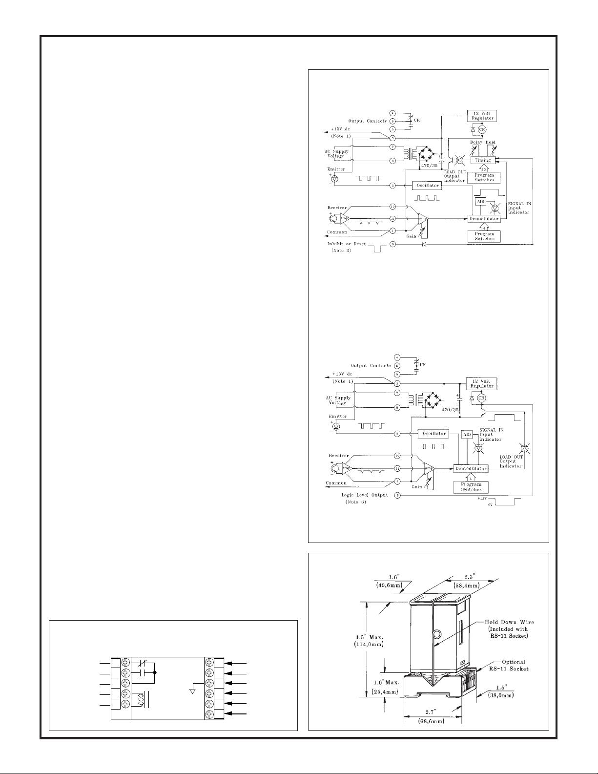
Functional Schematics
Models CD5RA, CD5RB
NOTE #1: power is available at pins #3 (+) and #1 (-) for an external 10 to 30V dc
device (see hookup example, page 9). Current available is 40 mA at 120V ac (240V
ac) line level; 30mA at 105V ac (210V ac) line level. Alternately, the module may be
powered by 12 to 28V dc at pins #3 (+) and #1 (-). Do not connect ac voltage when
using external dc power.
NOTE #2: pulling pin #9 low (to common) will inhibit the timing, or reset the latch
of CD5 models (see "Description of Logic Functions", page 6).
Models CD3RA, CD3RB
NOTE #3: pin #9 of CD3 models may be connected directly as the input to Banner CL
Series MAXI-AMPs or to Banner MICRO-AMP™ or Plug Logic modules (see
hookup example, page 9).
Dimension Drawing
Generalized Hookup:
models with electromechanical relay output
SPDT 5A
Relay
Output
CD3RA
AC
Supply
87654
CD3RB
CD5RA
CD5RB
4
LED +
LED -
Common
PT PT +
Auxiliary
9 10 11 1 2 3
(see table)
Page 5
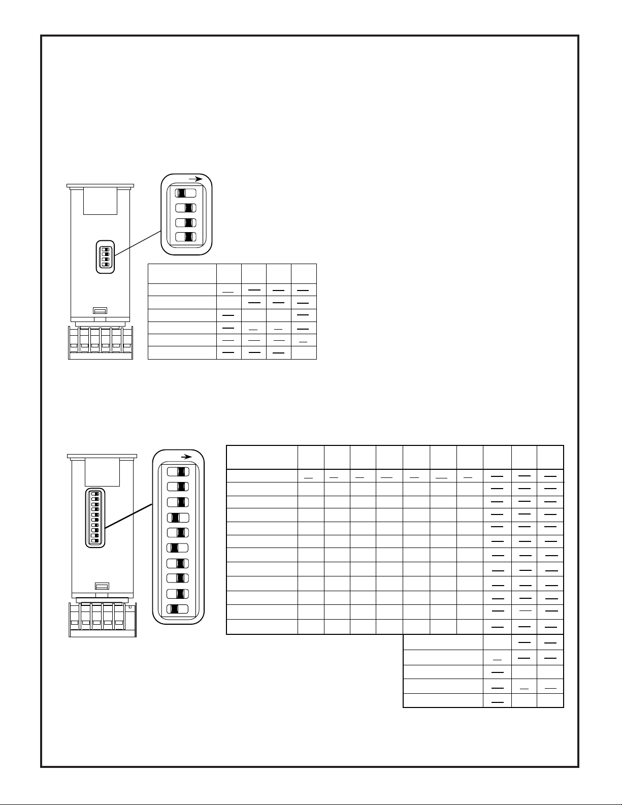
Amplifier Programming (all CD Series modules)
f
Amplifier response conditions may be programmed via the group of four
switches located on one of the narrow sides of the MAXI-AMP™
module.
Switch #1 selects the modulation frequency of the amplifier and the
emitter light source. When two pairs of SP12 Series sensors are being
used in close proximity to each other, the modulation frequency switch
of their respective CD Series modules should be set to different modula-
ON
O
1
F
F
2
3
4
AMPLIFIER
PROGRAMMING
Modulation freq. "A"
Modulation freq. "B"
1.5 millisecond response
15 millisecond response
Light operate
Dark operate
Factory settings are
shown at left. The
"underlined" settings in
table below are factory
settings.
SWITCH SWITCH SWITCH SWITCH
#1 #2 #3 #4
OFF
ON
OFF
OFF
ON
ON
ON
OFF
tion frequencies. This makes it possible to use the two sensor pairs
in close proximity without optical crosstalk. Both amplifiers must
be set for the same response time (either 1.5 or 15 milliseconds) to
ensure freedom from crosstalk.
Switches #2 and #3 are used to program the amplifier response
time. The 15 millisecond setting allows SP12 Series sensors to
operate at their maximum excess gain.
Switch #4 is used to select LIGHT OPERATE or DARK OPER-
ATE. In the LIGHT OPERATE mode, the output will energize (in
ON/OFF or LATCH operation) or the timing function will initiate (in
DELAY, ONE-SHOT, or LIMIT operation) when the receiver
"sees" sufficient light (excess gain greater than 1X). In DARK
OPERATE, the output will energize or timing will begin when the
receiver is sufficiently dark (excess gain less than 1X).
The diagram at the left shows the location of switches 1-4,
and the table summarizes the settings required for each
response condition.
NOTE: An adhesive-backed mylar label is supplied. It may
be marked to indicate switch programming and then applied to the MAXI-AMP housing as a switch cover.
Timing Logic Programming (CD5 models)
Settings illustrated below are factory settings. Factory settings are "underlined" in the table.
ON
O
1
F
F
2
3
4
5
6
7
8
9
10
TIMING LOGIC
PROGRAMMING
On/Of
On Delay
Off Delay
On and Off Delay
One-shot
Delayed One-shot
Limit
Repeat Cycle
AC Latch
DC Latch
Delay and Latch
Limit and Latch
A group of ten switches, located on the side of the module opposite the amplifier program
switches, is used to select the timing logic for the CD5 models.
Switches #1 through #7 are used to select the logic function. Switch #8 programs the output for
either NORMALLY OPEN or NORMALLY CLOSED operation. Switches #9 and #10
program the time range(s). There are three ranges: 10 to 150 milliseconds, 0.1 to 1.5 seconds,
and 1 to 15 seconds. The programmed range will be the same for both functions of a dual timing
mode (ON & OFF DELAY, DELAYED ONE-SHOT, and REPEAT CYCLE). However,
DELAY and HOLD times are independently adjustable within the selected range.
SWITCH SWITCH SWITCH SWITCH
#1 #2 #3 #4 #5 #6 #7 #8 #9 #10
ON ON OFF ON
ON
ON ON OFF ON OFF ON
ON OFF ON OFF ON OFF
OFF OFFOFF OFF OFF
ON ON ONOFFOFF OFFOFF
ON
OFF ON ON OFF
ON
ON ON OFF OFF ONONON
ON ON OFF OFF OFF ONON
OFF
OFF OFFOFF OFF ON
ONOFFOFF OFF ON OFF ON
OFF
OFF
OFF ON ON OFF ON
ONON OFF ONONON
SWITCH SWITCH SWITCH SWITCH SWITCH SWITCH
ON
OFF
ON
ONON
ON
ONONON
N/C Output
N/O Output
.15 Sec. Max. Time
1.5 Sec. Max. Time
15 Sec. Max. Time
OFF
ON
OFF OFF
OFF
ON
ON
OFF
The diagram shows switch locations, and the
table summarizes the program switch positions.
5
Page 6
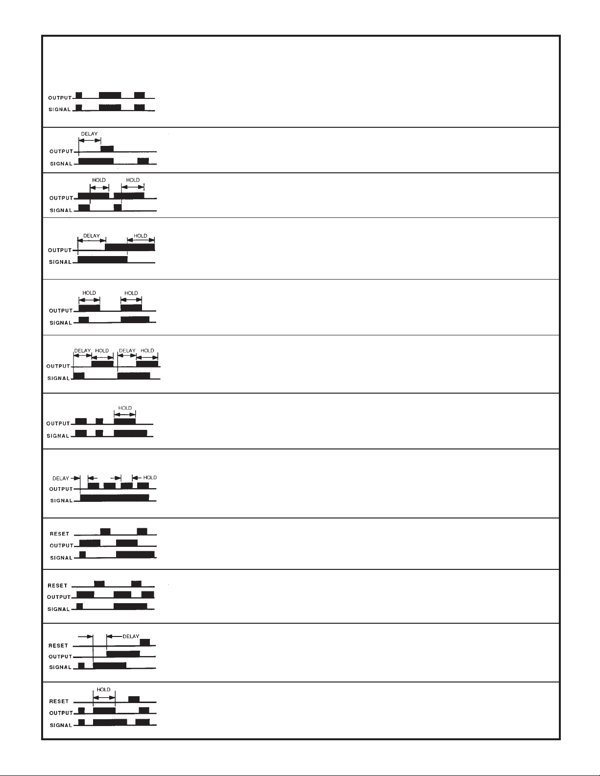
Description of Logic Functions for CD5, CL5, CM5, and CR5 models
ON/OFF: ON/OFF operation does not involve timing. The output simply follows the action of the input signal.
Grounding pin #9 (AUXILIARY) turns the output "off", regardless of the state of the input signal. This may be accomplished
by closing a switch or relay contact between pins #9 and #1 (common), or by connecting an open collector NPN (current sinking)
output of any external dc device directly to pin #9. NOTE: connect the COMMON of any external dc device to pin #1 of the
MAXI-AMP to establish a voltage reference between the dc supply for the external device and the internal dc supply of the
MAXI-AMP.
ON DELAY: The ON DELAY timer keeps the output "off" until the selected LIGHT or DARK signal has been present
for the preset "DELAY" time. If the input signal is interrupted, the timing is reset and starts over with the next signal. Grounding
pin #9 immediately cancels an output in progress and resets the delay timer. The delay timer is restarted when the inhibit signal
is removed, if an input signal is present.
OFF DELAY: The output energizes immediately when the input signal occurs, but does not de-energize until the signal
has been removed for the preset OFF-DELAY ("HOLD") time. Grounding pin #9 prevents an output from occuring. If an
inhibit input occurs during an output, the output remains "on" for the remainder of the OFF-DELAY time.
ON & OFF DELAY: ON and OFF DELAY logic combines both timing functions into a single mode. The ON-
DELAY ("DELAY") time and the OFF-DELAY ("HOLD") time are independently adjustable within the selected time range.
Momentary grounding of pin #9 during the ON-DELAY period resets the DELAY timer. An inhibit signal which occurs during
an output will allow the output to stay energized for the remainder of the OFF-DELAY time. ON and OFF DELAY logic is
often used in jam and void control, high/low level control, and edge-guiding applications.
ONE-SHOT: The output of a ONE-SHOT function is a pulse of adjustable "HOLD" duration which is independent
of the duration of the input signal. With the MAXI-AMP programmed for LIGHT operate, the pulse occurs when the input
signal changes from dark to light. In DARK operate, the pulse occurs with a light to dark input transition. Grounding pin #9
prevents the one-shot from triggering, but does not affect a pulse already under way.
DELAYED ONE-SHOT: A DELAYED ONE-SHOT is initiated by either a momentary or maintained input
signal. This input starts the adjustable "DELAY" period, after which the output pulses for an adjustable pulse ("HOLD") time.
No further action occurs unless the input is removed and reapplied, beginning a new sequence. Grounding pin #9 during the
delay period will cancel the sequence, and no output occurs. This feature is often used for inspection/rejection control logic.
An inhibit signal will not affect a pulse under way.
LIMIT: The output of the LIMIT function follows the action of the input, as it does with the ON/OFF function. However,
an input signal which is longer than the adjustable LIMIT ("HOLD") time will turn the output "off". Removing the input signal
resets the timer. This function is sometimes called "TIME LIMITED ON/OFF", and is useful for energy conservation.
Grounding pin #9 cancels the output. Lifting the inhibit restarts the LIMIT timer, if an input signal is present.
REPEAT CYCLE: The REPEAT CYCLE function provides an oscillating output when an input signal is present.
Presence of an input signal triggers an adjustable "DELAY" timer. After the delay, the output energizes for an adjustable
"HOLD" period. If the input remains, the output continues to cycle "on" and "off" at this rate indefinitely. When the signal
is removed, any output in progress completes and then remains "off" until the next signal and DELAY period. Grounding pin
#9 cancels the sequence, but will allow the completion of a "HOLD" period in progress. Lifting the inhibit signal begins the
DELAY period, if an input signal is present.
AC LATCH: An AC LATCH is the combination of a ONE-SHOT and a LATCH. A momentary or sustained input
will latch the output "on". Grounding pin #9 will reset the latch, even if the input signal remains. The output will not re-latch
until the input signal is removed and then reapplied.
DC LATCH: The output will latch "on" whenever the selected LIGHT or DARK input condition occurs. Grounding
pin #9 of a dc latch will turn the output "off" regardless of the state of the input signal. If the signal is present when the reset
is removed, the output will immediately latch "on" again.
DELAY AND LATCH: The DELAY + LATCH is a combination of the ON-DELAY and DC LATCH functions.
An input must be present for at least the adjustable "DELAY" time for the output to latch "on". If the input signal is removed
during the timing cycle, the timing is reset. Momentary grounding of pin #9 resets the latch and/or the DELAY timing cycle.
Sustained grounding of pin #9 inhibits any output.
LIMIT AND LATCH: The LIMIT + LATCH operates exactly like the LIMIT function, except that the LIMIT
("HOLD") timer can be reset only by the auxiliary input. An output remains latched "off" until reset by momentarily grounding
pin #9. In addition to resetting the timer, grounding pin #9 will hold the output "off", regardless of the state of the input signal.
6
Page 7
0
MAXI-AMP
System
SP12 Series Opposed Mode Remote Modulated Barrel Sensors
for use with MAXI-AMP CD Series Modules
Leakproof NEMA 6P threaded-barrel opposed mode
™
•
remote sensor pairs; VALOX® or stainless steel housing
Compact and powerful: 1/2" (12mm) in diameter by 2"
•
long; 200-foot sensing range. Apertures are available.
Special preamplified circuit design for noise immunity
•
equal to that of self-contained sensors
Banner SP12 Series sensors are a family of powerful, modulated,
totally-encapsulated opposed mode remote sensor pairs in compact,
threaded-barrel type housings. They are the ideal choice for applications that require high excess gain together with small size in difficult
sensing environments. SP12 Series sensors are especially effective at
penetrating heavy contaminants when used at close range.
The preamplified design of these sensors results in exceptional noise
immunity. Signals carried along remote receiver cables are often
subject to interference (from electrical noise sources) that can be as
strong as (or stronger than) the desired light signal. The severity of this
problem often worsens with increasing sensor cable length. SP12
Series receivers contain a preamplifier that immediately boosts the
received light signal to a high level before sending it down the cable to
the rest of the sensing system.
SP12 Series sensors are designed for use with the Banner CD Series
MAXI-AMP™ modules. CD Series modules provide sensor power,
additional amplification, a choice of several programmable timing
logic functions (CD5 models), and output circuitry for interfacing to
a load. They also allow two different programmable sensor modulation
frequencies, making it possible to use multiple high-powered sensor
pairs in close proximity to each other without optical crosstalk. CD
Series modules are available for a wide range of supply voltages. Each
CD module powers one SP12 emitter/receiver pair. See page 3 for more
information.
SP12 sensors are rated NEMA 6P (IEC IP67) for use in wet locations.
There is a choice of either VALOX
table, below). Positive sealing at both ends of the sensors, with no
exposed epoxy interfaces, eliminates all leak paths (including capillary
leakage). Electronics are fully encapsulated for maximum resistance to
mechanical shock and vibration. Lenses are acrylic, and quad-ring
sealed. These sensors may be used with watertight, thread-on apertures to create very narrow, very powerful effective beams (see next
page).
A 1/2" clearance hole is required for mounting. Alternatively, the
Banner model SMB12MM mounting bracket may be used (see next
page). SP12 Series sensors are supplied with 6-1/2 feet of PVCcovered attached cable, or QD connectors (page 8). Options for models
with attached cable are summarized below. The maximum recommended emitter or receiver cable length is 100 feet (each).
®
or stainless steel housing style (see
SP12 Series sensors (foreground) shown with MAXI-AMP™
CD Series amplifier and logic
modules (see pages 3-6).
Models are also available with QD connectors (page 8).
Beam PatternExcess Gain Curve
100
E
X
C
100
E
S
S
G
10
A
I
I
N
0
1 FT
SP12 Series
opposed mode
emitters and
receivers
15ms
response
1.5ms
response
10 FT 100 FT 1000FT
DISTANCE
60
40
I
20
N
C
0
H
E
20
S
40
60
SP12 Series emitters
and receivers
1.5ms response
15ms response
80 120 160 200
400
OPPOSED DISTANCE--FEET
Specifications, SP12 Sensors
SUPPLY VOLTAGE: sensors are powered from a Banner CD Series
MAXI-AMP™ module (see page 3).
RANGE: up to 200 feet in opposed mode (see gain curve, above).
RESPONSE SPEED: selectable for 1.5 or 15 milliseconds; a function
of the MAXI-AMP CD Series module.
LIGHT BEAM: infrared LED, 880nm. Effective beam diameter: 3/8".
CONSTRUCTION: NEMA 6P.
12mm diameter tubular threaded VALOX
positive sealing at both ends, quad-ring sealed acrylic lens. Electronics
fully epoxy-encapsulated. Two jam nuts are provided: VALOX® for
VALOX
®
units; stainless steel for stainless steel units. Mounting
requires 1/2" diameter clearance hole.
OPERATING TEMPERATURE: -40 to +70°C (-40 to +158°F).
CABLE: sensors are supplied with 6-1/2 feet of PVC-covered 2- or 3-
conductor cable. Models with QD connectors are available (page 8).
VALOX® is a registered trademark of General Electric Co.
®
or stainless steel housing;
SP12 Series Barrel Sensors
Model Type Housing Material
SP12SEL
SP12PEL
SP12SRL
SP12PRL
NOTE: Models with 30-foot attached cable are available (contact factory
for information). 2- and 3-conductor 50- and 100-foot extension cables
(without connectors) are also available. For 2-conductor (emitter) cable:
order model EC12E-50 (50') or model EC12E-100 (100'). For 3-conductor
(receiver) cable: order model EC12R-50 (50') or model EC12R-100 (100').
Emitter
Emitter
Receiver
Receiver
Stainless steel
VALOX
®
Stainless steel
VALOX
®
Dimension Drawing
7
Page 8
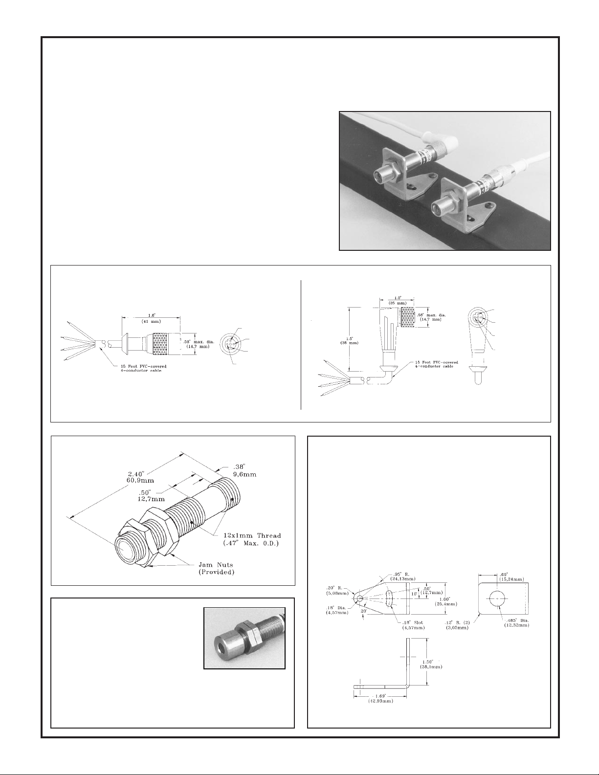
SP12 Series Opposed Mode Remote Modulated Barrel Sensors
with Quick Disconnect (QD) Cable Option
The stainless steel models of SP12 Series modulated remote barrel sensors
may be ordered with a built-in connector designed to mate with eurofast™
quick-disconnect (QD) cables. The resultant sensor model numbers are:
SP12SELQD (emitter), and
SP12SRLQD (receiver).
he mating cables are ordered separately. Cables are available in 15 foot
T
lengths with either of two styles of mating connector. Cable model MQDC415 has a straight connector, and model MQDC-415RA has a right-angled
connector (see drawings below). In both models, the plug body is molded
to the PVC cable for waterproof integrity. Plug contacts are gold-plated.
Dimensional Information for MQDC-415 Cable
White wire
Blue wire
Black wire
Brown wire
Dimension Drawing
Dimensional Information for MQDC-415RA Cable
White wire
Blue wire
Black wire
Brown wire
Model SMB12MM Mounting Bracket
Model SMB12MM is a stainless steel mounting bracket for SP12
Series sensors. The sensor mounts to the bracket using the two jam
nuts supplied with the sensor. This rugged, slotted bracket allows
±10 degrees of lateral movement. Bracket is 12-gauge stainless
steel. The bracket mounting holes accommodate #8 hardware.
SMB12MM bracket:
Apertures
Rectangular and circular thread-on watertight apertures are available for SP12
sensors. Apertures are used to shape and
size the sensor's effective beam and to
protect the sensor's lens. Use of apertures
with these high-gain sensors makes it
possible to create very narrow, concentrated sensing beams for
demanding applications. Aperture Kit AP12SC includes three
round apertures with openings of .02", .04". and .10" diameter.
Aperture kit AP12SR has three rectangular apertures .02", .04",
and .10" wide. Both include lens, o-rings, and thread-on housing.
8
Page 9

r
r
r
r
SP12 Sensor Hookup to CD Series MAXI-AMP™ Modules
1) Hookup of SP12 Series Sensors (all models)
SP12 Series sensors are especially designed for use with CD Series modules. The basic hookup is given here (QD sensor models shown). Each MAXI-AMP™
CD Series module supports use of one pair of SP12 Series sensors. CD5 Series module models also support use of a GATE or INHIBIT sensor at pin #9 (below,
this page).
Models with isolated solid-state contacts
DC Load
AC Load
Load Common
AC
SUPPLY*
CD3A
87654
CD3B
CD5A
CD5B
LED + (white)
LED - (green)
2 3
COMMON (black)
1
PT - (blue)
PT + (brown)
9 10 11
Emitter
AUX
Receiver
Models with electromechanical relay contacts
SPDT 5A
Relay
Output
AC
SUPPLY*
LED + (white)
LED - (green)
CD3RA
87654
CD3RB
CD5RA
CD5RB
COMMON (black)
PT - (blue)
PT + (brown)
9 10 11 1 2 3
AUX
Emitter
Receiver
*105 to 130V ac or 210 to 250V ac, 50/60Hz, depending on model. To power the MAXI-AMP™ module from a dc supply, connect
+12 to 28V dc at ≥70mA to terminal #3 and dc common to terminal #1. Make no connection to terminal #7 or #8.
2) Logic Level NPN Output (CD3 models)
The AUXILIARY terminal (#9) of models CD3A, CD3B, CD3RA and
CD3RB modules offers a logic-level NPN (current sinking) output which may
be used as a fast-response solid-state inhibit signal to the AUXILIARY input
of MAXI-AMP CD5, CL5, CM5, or CR5 Series modules. This output may
also serve as an input to any MICRO-AMP™, Plug Logic, or CL
AC
Supply
54
6
CM5
7
models
8
1 2 3
10 11
9
Series logic module. In addition,
this output may interface to other dc
devices or circuits like counters,
rate meters, or programmable logic
controllers. Switching capacity is
20mA maximum at 12V dc max.
AC
Supply
4
5
CD3
models
876
2 3
1
11
10
9
The example here shows the use of
SP12 Series sensors and a CD3 module to provide inspection information, with the SP300D functioning
as a product (GATE) sensor.
SP300D
(Inspection)
SP12 Series Emitte
white
green
black
red
Inhibit
white
green
black
blue
brown
Gate
(Interrogate)
See Hookup Diagram #1 (above) for load and power connection information.
Typically, the CM5 module would
be programmed for the ONE-SHOT
or DELAYED ONE-SHOT logic
function. If the SP12 pair "sees" an
acceptable condition when the
SP300D senses the leading (or trailing) edge of a product, the CD3 will
inhibit a reject pulse from occuring.
Data
SP12 Series Receive
3) Power for External Devices (all models)
External 10 to 30V dc devices such as
self-contained sensors may be connected
between terminals #3 (+) and #1 (-) of
any CD series MAXI-AMP module.
Terminal #3 offers 40mA maximum.
This is sufficient to power most Banner
self-contained dc sensors.
As the example at the right illustrates,
the current sinking output of a self-
contained sensor powered by the MAXIAMP may be used as the input to the
AUXILIARY terminal of a CD5 module.
AC
Supply
87654
+15V dc @40mA
CD5
models
NOTE: Black wire from
SE612
is not used
Inhibit
GATE
white
green
black
1 2 3
blue
brown
9 1011
White
Brown
+15V dc
(#3)
SP12 Series Emitte
DATA
(Inspection)SE612
Blue
(#1)
(Interrogate)
SP12 Series Receive
9
Page 10

MAXI-AMP™ CM Series
Modulated Amplifier Modules
CM Series MAXI-AMPs combine power supply, modulated photoelectric amplifier, timing logic (in CM5 models) and output relay in a
single compact, cost-saving module. CM-series modules work together with the popular family of Banner high-performance modulated
remote sensors (pages 13-17). These sensors offer small size and
excellent optical performance, and are built to operate in highly
demanding sensing environments. MAXI-AMP modules themselves
are also ruggedly built for dependable industrial duty.
CM Series MAXI-AMP modules contain the state-of-the-art Banner
custom-designed CMOS modulator/demodulator/amplifier circuit, offering high immunity to both ambient light and electrical interference
plus reliable sensor performance. All models have Banner's exclusive,
patented Alignment Indicating Device ("AID™") system, which lights
an LED indicator whenever the sensor sees a "light" condition, and
pulses the LED at a rate proportional to the received light signal
strength.
All CM Series modules are programmable for LIGHT or DARK
operate and either high or low hysteresis. Input response time may be
set at 0.3, 2, or 10 milliseconds. The 10-millisecond response mode
offers enhanced immunity to electrical interference ("noise"), and also
Recognized Certified
MODEL
CM3RA
CM3RB
CM5RA
CM5RB
minimizes optical "crosstalk" between adjacent sensors. Unlike other
amplifier designs, input response time settings of the CM Series
modules do not affect sensor range.
CM5 models include a versatile multi-function timing logic circuit
which is programmable for 12 of the most popular and useful delay,
one-shot, and latch functions (see page 6). Each timing function has a
choice of three time ranges. Timing and sensitivity adjustments are
accomplish-ed via rugged 15-turn potentiometers for very accurate
settings. CM Series circuitry is designed to prevent false outputs on
system power-up.
An auxiliary input is available on CM5 models for interrogation or reset
of the selected logic function (see example, page 17). Page 6 describes
the function of the auxiliary input for each logic mode. A dc power
supply is included for powering an additional self-contained dc sensor.
The output circuit for all CM Series modules is an SPDT 5-amp electromechanical relay. Additionally, CM3 models have an NPN transistor
solid-state switch. The output may be programmed for either normally
open or normally closed operation. A solid-state relay is offered as an
option to the electromechanical relay (see information below).
SUPPLY
VOLTAGE
105 to 130V ac, or
12 to 28V dc
210 to 250V ac, or
12 to 28V dc
105 to 130V ac, or
12 to 28V dc
210 to 250V ac, or
12 to 28V dc
OUTPUT
SPDT electromechanical
relay, plus NPN
transistor solidstate DC switch
SPDT electromechanical relay
(5 amp contact
rating)
LOGIC
ON/OFF
12
timing
functions
Solid-state Output Option
CM Series modules are available with a solid-state relay which replaces the
electromechanical relay. This is actually two SPST solid-state contacts. One
contact will switch ac loads. The contact is rated at 250V ac maximum and
3/4 amps maximum at 25 degrees C (derated to 1/2 amp at 50 degrees C). The
other solid-state contact will switch dc loads of up to 30V dc and up to 50
milliamps. Both contacts are isolated from the MAXI-AMP power supply.
MODEL
CM3A
CM3B
CM5A
CM5B
SUPPLY
VOLTAGE
105 to 130V ac, or
12 to 28V dc
210 to 250V ac, or
12 to 28V dc
105 to 130V ac, or
12 to 28V dc
210 to 250V ac, or
12 to 28V dc
OUTPUT
SPST solid-state
contact for
switching AC
loads up to 250
V ac and up to
3/4 amp, plus
solid-state contact for switching DC loads up
to 30V dc and up
to 50mA.
MAXI-AMP CR Series Modulated Modules for SP100 Series Miniature Remote Sensors
The amount of amplification available from CM Series MAXI-AMP
modules is too high to operate with the Banner SP100 Series of
miniature modulated remote sensors. CR Series modules correct this
incompatibility with a modified modulated amplifier design. CR Series
specifications are exactly the same as for the standard CM Series
models (listed above) except for the difference in amplifier gain.
Available models are listed in the table at the right.
SP100 Series sensors are ideal for OEM machinery and for tight spaces
where the use of photoelectric sensors was previously considered
impossible. The SP100 Series is described in the Banner catalog.
CR Series modules are also available with the solid-state output option
(see above).
MODEL
CR3RA
CR3RB
CR5RA
CR5RB
SUPPLY
VOLTAGE
105 to 130V ac, or
12 to 28V dc
210 to 250V ac, or
12 to 28V dc
105 to 130V ac, or
12 to 28V dc
210 to 250V ac, or
12 to 28V dc
OUTPUT
SPDT electromechanical
relay, plus NPN
transistor solidstate DC switch
SPDT electromechanical relay
(5 amp contact
rating)
LOGIC
ON/OFF
12
timing
functions
LOGIC
ON/OFF
12
timing
functions
10
Page 11

MAXI-AMP CM and CR Series Specifications
SUPPLY VOLTAGE: Models CM3(R)A, CM5(R)A, CR3(R)A, and
CR5(R)A: 105 to 130V ac, 50/60Hz (4 VA), or 12 to 28V dc* at 70mA.
Models CM3(R)B, CM5(R)B, CR3(R)B, and CR5(R)B: 210 to 250V ac, 50/
60Hz (4 VA), or 12 to 28V dc* at 70mA.
*NOTE: do not connect ac power if using external dc power.
OUTPUT CONFIGURATION:
Models CM3A, CM3B, CM5A, CM5B, CR3A, CR3B, CR5A, CR5B have
SPST solid-state relay for switching ac or dc (see page 10).
Models CM3RA, CM3RB, CM5RA, CM5RB, CR3RA, CR3RB, CR5RA,
CR5RB have SPDT electromechanical (e/m) relay with the following ratings:
CONTACT RATING: 250V ac max, 24V dc max, 5 amps max. (resistive load),
1/10 H.P. at 240V ac. Install transient suppressor (MOV) across contacts which
switch inductive loads.
CONTACT RESPONSE: 10 milliseconds max. open/close;
20 operations/second max.
MECHANICAL LIFE: 20,000,000 operations
CM3 and CR3 models also have a logic level current sinking NPN transistor
switch at pin #9. See schematic (right) and hookup info.
AMPLIFIER:
RESPONSE SPEED: programmable for 10, 2, or 0.3 milliseconds. NOTE: use
10 millisecond setting whenever possible for enhanced noise rejection.
HYSTERESIS: if programmed "HIGH", approximately 20%; if programmed
"LOW", approximately 5%. NOTE: see cautions for "LOW" setting, page 12.
MODULATION FREQUENCY: approximately 10kHz.
SENSOR LEAD LENGTH: 50 feet (15 m) maximum. Use separate
shielded cable for emitter and receiver, or order sensors with extended cable
length. NOTE: see splicing precautions, page 17.
MULTIPLE SENSOR HOOKUP: Up to three sensors may be wired
together to one CM-series amplifier for "OR" operation (in LIGHT operate) or
"NAND" operation (in DARK operate). Emitters are connected in series, and
receivers are connected in parallel. When wiring two sensors to one MAXIAMP, multiply excess gain data for each sensor by 1/2 (obtain data from
applicable excess gain curve). When wiring three sensors to one MAXI-AMP,
multiply excess gain by 1/3.
TIMERS (CM5 models only):
TIMING RANGES: LOW range - 10 to 150 milliseconds
REPEATABILITY: +/-2% of set time over all extremes of supply
MIDDLE range - 0.1 to 1.5 seconds
HIGH range - 1 to 15 seconds
voltage and temperature
ADJUSTMENTS: Miniature switches for programming of LIGHT/ DARK
operate, amplifier response time, amplifier hysteresis, normally open or normally closed output, and timing function (CM5 & CR5 models). 15-turn
clutched potentiometer for gain and time setting(s) (CM5 and CR5 models).
OPERATING TEMPERATURE: 0 to 50°C (32 to 122°F).
INDICATOR LEDs: Red indicator LED is "ON" when the module output
is energized. Exclusive Banner Alignment Indicating Device (AID™) system
lights a red LED indicator whenever the receiver "sees" its own modulated light
source, and pulses it at a rate which is proportional to the strength of the received
light signal.
CONSTRUCTION: Rugged NORYL
ing, 1.6" x 2.3" x 4". Standard round-pin 11-pole plug base.
®
polyphenylene oxide (PPO®) hous-
Functional Schematics
CM5 & CR5 Models
NOTE #1: power is available at pins #3 (+) and #1 (-) for an external 10 to 30V dc
device (see hookup example, page 17). Current available is 40 mA at 120V ac (240V
ac) line level; 30mA at 105V ac (210V ac) line level. Alternately, the module may
be powered by 12 to 28V dc at pins #3 (+) and #1 (-). Do not connect ac voltage if using
external dc power.
NOTE #2: pulling pin #9 low (to common) will inhibit the timing, or reset the latch
of CM5 or CR5 models (see "Description of Logic Functions", page 6).
CM3 & CR3 Models
NOTE #3: pin #9 of CM3 or CR3 models may be connected directly to the
AUXILIARY input of a MAXI-AMP or Banner M Series module. It may also serve
as the input to Banner CL series MAXI-AMPs or to Banner Plug Logic modules (see
hookup example, page 17).
Dimension Drawing
Generalized Hookup
models with electromechanical relay output
NOTE: If MAXI-AMP is powered by a dc power supply, connect +12 to 28V dc
@ ≥70mA to terminal #3 and dc common to terminal #1.
Make no connections to terminal #7 or #8.
11
Page 12

Amplifier Programming (all models)
Amplifier response conditions may be programmed via the group of four
switches located on one of the narrow sides of the MAXI-AMP module.
Switch #1 selects the amount of amplifier hysteresis. Hysteresis is the
amount of signal change beyond the switching threshold which is
required to cause the amplifier output to change state, and is expressed
as a percent of amplifier gain. The NORMAL setting of 20% should
always be used, except for low contrast situations such as many color
registration applications.
ON
1
O
F
F
2
3
4
AMPLIFIER
PROGRAMMING
Normal hysteresis (20%)
Low hysteresis (5%)
10 millisecond response
2 millisecond response
0.3 millisecond response
Light operate
Dark operate
Factory settings shown at
left. "Underlined" settings
in table below are factory
settings.
SWITCH SWITCH SWITCH SWITCH
#1 #2 #3 #4
ON
OFF
OFF
ON
ONON
ON
OFF
ON
OFF
NOTE: the LOW hysteresis setting should be used only when all
sensing conditions remain stable. "Buzzing" of the output (in ON/
OFF and LIMIT operation) or false outputs (in DELAY, ONESHOT, or LATCH operation) may occur if sensing variables (e.g.-
web flutter) result in optical contrast approaching unity.
Switches #2 and #3 are used to program the amplifier response time.
The 10 millisecond setting should be used whenever possible for the
greatest immunity to electrical interference ("noise"). The 2 millisecond setting has more interference rejection than the 0.3 millisecond
mode. Sensor performance (excess gain) is identical in all three
response settings.
Switch #4 is used to select LIGHT OPERATE or DARK
OPERATE. In the LIGHT OPERATE mode, the output will
energize (in ON/OFF or LATCH operation) or the timing
function will initiate (in DELAY, ONE-SHOT, or LIMIT
operation) when the receiver "sees" sufficient light (excess
gain greater than 1X). In DARK OPERATE, the output will
energize or timing will begin when the receiver is suffi-
ciently dark (excess gain less than 1X).
The diagram at the left shows the location of switches 1-4,
and the table summarizes the settings required for each
response condition.
NOTE: an adhesive-backed mylar label is supplied, which
may be marked to indicate switch programming and then
applied to the MAXI-AMP housing as a switch cover.
Timing Logic Programming (CM5 and CR5 models)
Settings illustrated below are factory settings. Factory settings are "underlined" in the table.
ON
1
O
F
F
2
3
4
5
6
7
8
9
10
TIMING LOGIC
PROGRAMMING
On/Off
On Delay
Off Delay
On and Off Delay
One-shot
Delayed One-shot
Limit
Repeat Cycle
AC Latch
DC Latch
Delay and Latch
Limit and Latch
A group of ten switches, located on the side of the module opposite the amplifier program
switches, is used to select the timing logic for the CM5 and CR5 models.
Switches #1 through #7 are used to select the logic function. Switch #8 programs the output
for either NORMALLY OPEN or NORMALLY CLOSED operation. Switches #9 and #10
program the time range(s). There are three ranges: 10 to 150 milliseconds, 0.1 to 1.5 seconds,
and 1 to 15 seconds. The programmed range will be the same for both functions of a dual
timing mode (ON & OFF DELAY, DELAYED ONE-SHOT, and REPEAT CYCLE).
However, DELAY and HOLD times are independently adjustable within the selected range.
SWITCH SWITCH SWITCH SWITCH
#1 #2 #3 #4 #5 #6 #7 #8 #9 #10
ON ON OFF ON
ON
ON ON OFF ON OFF ON
ON OFF ON OFF ON OFF
OFF OFFOFF OFF OFF
ON ON ONOFFOFF OFFOFF
ON
OFF ON ON OFF
ON
ON ON OFF OFF ONONON
ON ON OFF OFF OFF ONON
OFF
OFF OFFOFF OFF ON
ONOFFOFF OFF ON OFF ON
OFF
OFF ON ON OFF ON
ONON OFF ONONON
SWITCH SWITCH SWITCH SWITCH SWITCH SWITCH
OFF
ONON
ON
OFF
N/C Output
N/O Output
.15 Sec. Max. Time
1.5 Sec. Max. Time
15 Sec. Max. Time
The diagram shows switch locations, and the
table summarizes the program switch
positions.
ON
ON
ONONON
OFF
ON
OFF OFF
OFF
ON
ON
OFF
12
Page 13

MAXI-AMP System
Sensors for use with CM Series Modulated Amplifiers
Sensors are epoxy-encapsulated and optics are hermetically sealed. Cables are 6 feet (2m) long. 30-foot (9m) cables available by special order.
Sensor accessories are shown on page 24.
OPPOSED Mode
ALL MODELS:
Range: 8 feet (2,4m)
Beam: infrared, 880nm
Effective Beam:
.14 inch (3,6mm) dia.
LR models are emitters
PT models are receivers
LR200 & PT200
Temp. range: -40 to +100 degrees C
Housing material: black Delrin
LR250 & PT250 LR300 & PT300 LR400 & PT400
Temp. range: -40 to +100 degrees C
®
Housing material: black Delrin
Excess GainModels/Dimensions
1000
E
X
C
100
E
S
S
G
10
A
I
I
N
1
.1 FT 1 FT 10 FT 100 FT
Temp. range: -40 to +80 degrees C
®
Housing material: black VALOX
LR/PT200, 250,
300, & 400
DISTANCE
Beam Pattern
12
8
I
4
N
C
0
H
E
4
S
8
12
Temp. range: -40 to +100 degrees C
®
Housing material: anodized alum.
LR/PT200, 250,
300, 400
20
4 6 8 10
OPPOSED DISTANCE--FEET
LR/PT200, 250, 300, and 400 opposed mode remote sensors are
identical electronically and optically, and differ only in their housings.
All are totally epoxy-encapsulated and use hermetically sealed glass
lenses to eliminate condensation inside the optical chamber. These
sensors may be washed down without damage. Operating temperature
is determined by the type of cable used (see specifications above).
These sensor pairs feature wide beam angle for forgiving line-of-sight
alignment. At the same time, the effective beam of each pair is only
1/8 inch, allowing small-profile resolution and reliable response to fastmoving objects. LR models are emitters; PT models are receivers.
LR200 & PT200: this is a right-angle design which mounts through a
7/16 inch (12mm) diameter hole, using the steel jam nut which is
included. This pair is used most commonly on small conveyors when
it is desireable to run the cable directly down to a wireway.
LR250 & PT250: these sensors feature a 1/4 inch (6,4mm) diameter
smooth barrel design, and are usually held in place in a clearance hole
with a small set-screw. Optional mounting blocks (shown below) are
available. Model SMB250 holds the sensor in place with two setscrews. The block is then mounted to a bracket (like model SMB300,
page 15), or directly to a machine frame with two #6 screws. Block
model SMB250C holds an LR & PT250 together to converge at
approximately 1/2 inch ahead of the block.
SMB250 SMB250C
LR & PT300: this is a miniature right-angle design which is mounted
in place using two #4 screws. This pair uses a very flexible, low-profile
2-wire cable. Despite their small size, the optical performance of the
LR/PT300 is equal to the other remote sensor pairs.
LR400 & PT400: the 3/8 inch (9,5mm) diameter threaded barrel
design makes the LR/PT400 the most versatile and most popular remote
opposed sensor pair. They are easily mounted through clearance holes
using the jam nuts which are supplied. They may be used with optional
L4 or L16 lenses for extended range and/or higher excess gain. The
addition of an L4 lens on both the LR and PT400 will increase their
range from 8 feet to 40 feet and increase the excess gain at any distance
by a factor of 25X. A pair of L16 lenses will increase available excess
gain by a factor of 250X.
L4 lens
The LR/PT400 pair is often used at close range with optional AP400 aperture
assemblies to create a very small and well-defined effective beam for resolving
small profiles, increasing sensing repeatability, or easing response time requirements.
AP400 apertures
L16 lens
Aperture model
AP400-010
AP400-015
AP400-040
AP400-030R
Aperture size
.010" dia.
.015" dia.
.040" dia.
.030" x .125"
13
Page 14

MAXI-AMP System
Sensors for use with CM Series Modulated Amplifiers
Sensors are epoxy-encapsulated. Cables are 6 feet (2m) long. 30-foot (9m) cables available by special order.
Sensor accessories are shown on page 24.
Models/Dimensions Excess Gain
SP300EL &
SP300RL
Emitter-receiver pair SP300EL/RL are extremely rugged and are totally encapsulated in anodized aluminum housings. The threaded hub at the cable exit
allows for the use of flexible armored cable or protective PVC tubing with the
addition of compression gland model CF7-16 (page 24). This pair uses
SP300L
Range: 50 feet (15m)
Effective Beam: .5 inch (13mm) dia.
Temp. range: -40 to +100 degrees C
Housing material: anodized aluminum
Range: 15 feet (4,5m) with BRT-3
retroreflector
Temp. range: -40 to +80 degrees C
Housing material: blue anodized
aluminum
Beam Pattern
Long Range
OPPOSED Mode
1000
SP300EL/RL
E
X
C
100
E
S
S
SP300EL/RL
G
10
A
I
I
N
1
.1 FT 1 FT 10 FT 100 FT
DISTANCE
18
12
I
6
N
C
0
H
E
6
S
12
18
20
100
OPPOSED DISTANCE --FEET
30 40 50
collimating lenses to increase range. These sensors should also be used at short
ranges for their high excess gain or to avoid optical "crosstalk" in situations which
require several pairs to be mounted adjacent to one another.
RETROREFLECTIVE
Mode
NOTE: for complete information on retroreflective materials, see Banner catalog.
1000
E
X
100
C
E
S
S
G
10
A
I
I
N
SP300L
with
BRT-T tape
with
BRT-3 target
with
BRT-1 target
1
.1 FT 1 FT 10 FT 100 FT
DISTANCE
6
4
I
2
N
C
0
H
E
2
S
4
6
SP300L
with BRT-3 reflector
40
8 12 15 18
DISTANCE TO REFLECTOR--FEET
Model SP300L is a remote retroreflective sensor with the same rugged design
as the SP300EL/RL, described above. Its useable range is from 6 inches to 15
feet (0,2 to 4,5m) using the model BRT-3 retroreflector.
LP400WB
Range: 3 inches (76mm)
DIVERGENT
Mode
Temp. range:
-40 to +80 degrees C
Housing material: blue anodized
aluminum
"WB" in this model number designates "wide beam". The LP400WB is an
infrared divergent mode (wide angle diffuse mode) sensor which is particularly
14
If the object that is to break the beam has a shiny surface, then the SP300L and its
retroreflector should be mounted so that the beam is at an angle of 10 degrees or
more to that surface in order to eliminate false signals which are caused by proxing.
1000
LP400WB
E
X
100
C
E
S
S
G
10
A
I
I
N
1
.1 IN 1 IN 10 IN 100 IN
Range based on
90% reflectance
white test card
DISTANCE
1.5
1.0
I
.5
N
C
0
H
E
.5
S
1.0
1.5
DISTANCE TO 90% WHITE TEST CARD--INCHES
LP400WB
10
2 3 4 5
forgiving for reflectively sensing transparent or translucent materials or for
sensing objects with irregular surfaces (e.g.- webs with "flutter"). The optics are
such that even small threads or wires .005" (0,1mm) or greater in diameter may be
detected when they pass within .25" (6mm) of the sensor's plastic lens. Due to its
wide response pattern, the LP400WB should not be used for precise positioning
control, nor should it be mounted with its lens recessed into a hole.
Page 15

MAXI-AMP System
Sensors for use with CM Series Modulated amplifiers
Sensors are epoxy-encapsulated. Cables are 6 feet (2m) long. 30-foot (9m) cables available by special order.
Sensor accessories are shown on page 24.
Models/Dimensions
SP300D
Range: 12 inches (30cm)
Temp. range: -40 to +80 degrees C
Housing material: green anodized
aluminum
SP320D
Range: 12 inches (30cm)
Temp. range: -40 to +80 degrees C
Housing material: black VALOX
Excess Gain
Beam Pattern
DIFFUSE
Mode
®
1000
SP300D, SP320D
E
X
100
C
E
S
S
G
10
A
I
I
N
1
.1 IN 1 IN 10 IN 100 IN
DISTANCE
.6
.4
I
.2
N
C
0
H
E
.2
S
.4
.6
DISTANCE TO 90% WHITE TEST CARD--INCHES
SP300D: the SP300D is the diffuse mode version of the SP300L with the
same rugged aluminum housing and totally encapsulated construction. The
glass lenses are hermetically sealed, which eliminates any possibility of
condensation inside the lenses and allows operation in adverse environments like steam washdown and high vibration. The SP300D may be
mounted by its through-holes or with the SMB300 bracket, as shown below.
SP320D: model SP320D is identical to the SP300D, except for its housing.
The 320 is a miniature plastic package, designed to fit into very tight
locations. It mounts using two #4 (3mm) screws. The SP320D and the
SP300D are excellent for nearly any presence sensing application.
SP300D, 320D
30
6 9 12 15
SMB300
UNIVERSAL MOUNTING
BRACKET for
SP300 Sensors
SP1000V
Range: focus at 3.8 inches (96mm)
Temp. range: -40 to +80 degrees C
Housing material: black anodized
aluminum
CONVERGENT Mode
Accessory bracket model SMB300 is designed for 2-axis universal mounting of sensor models SP300EL, SP300RL, SP300L, and SP300D. These
sensors are affixed to the SMB300 with two #6 (3,5mm) screws. The
bracket, in turn, mounts with two #10 (5mm) screws.
In addition, as indicated by the dimension drawing, the SMB300 has a
clearance slot for mounting LR400, PT400, and LP400WB barrel sensors.
LR & PT200 sensors may be mounted with the SMB300, using its 7/16-20
threaded hole and steel jam nut, which is supplied with the sensors. LR250
and PT250 sensors may be used with the SMB300 when the SMB250 block
is used (see page 13). Also, two SMB250 blocks may be attached to the
SMB300 bracket and angled to mechanically converge an LR & PT250
sensor pair.
The SP1000V is a convergent mode sensor that produces a very small 0.1
inch (2,5mm) diameter sensing image at a point exactly 3.8 inches (96mm)
from its glass lenses. As the excess gain curve illustrates, the SP1000V has
a very sharp drop-off of gain beyond the focus point. This feature makes it
an excellent choice for detecting a small part which is only a fraction of an
inch in front of another surface, such as parts on a conveyor (viewed from
above). It is also ideal for fill level detection and for precise positioning
control, in lieu of opposed sensing.
1000
E
SP1000V
X
100
C
E
S
S
G
10
A
I
I
N
1
.1 IN 1 IN 10 IN 100 IN
DISTANCE
.090
.060
I
.030
N
C
0
H
E
.030
S
.060
.090
10
DISTANCE TO 90% WHITE TEST CARD--INCHES
SP1000V
2 3 5 4
15
Page 16

MAXI-AMP System
Sensors for use with CM Series Modulated Amplifiers
Sensors are epoxy-encapsulated and optics are hermetically sealed. Cables are 6 feet (2m) long. 30-foot (9m) cables available by special order.
Sensor accessories are shown on page 24.
Models/Dimensions
FIBER OPTIC Mode
glass fiber optics
FOF-400 Fiber optic Fitting
For complete information on glass
fiber optic assemblies and accessories, see Banner product catalog.
LR400 & PT400
with FOF-400 fittings and
fiber optics
Range: see excess gain curves
Temp. range: -40 to +100 degrees C
The threaded barrel design of the
LR400 and PT400 (see page 14) permit the connection of any Banner
glass fiber optic assembly by using
two model FOF-400 fittings. The
sensors are typically mounted
through 3/8 inch (10mm) diameter
clearance holes, with the FOF-400
fittings threaded onto them after
mounting. Setscrews in the fittings
lock the fibers in place, but allow
rapid replacement without disturbing any electrical wiring.
As the excess gain curves show, the
LR/PT400 combination produces a
high-performance fiber optic sensing system. With the amplifier's 1
millisecond response time, this system can be used for almost any fiberoptic requirement.
Fiber optic information:
IT13S: individual assembly
.06 in. (1,5mm) dia. bundle
IT23S: individual assembly
.12 in. (3mm) dia. bundle
BT13S:bifurcated assembly
.06 in. (1,5mm) dia. bundle
BT23S:bifurcated assembly
.12 in. (3mm) dia. bundle
L9: .5 in. (12mm) dia. lens
L16F: 1.0 in. (25mm) dia.
lens
1000
LR/PT400
E
X
100
C
E
S
S
with IT13S
G
fibers
10
A
I
I
N
1
.1 IN 1 IN 10 IN 100 IN
1000
E
X
C
100
E
S
S
G
10
A
Opposed mode,
I
I
with IT23S
N
fibers
1
.1 FT
1000
Retroreflective mode, with
BT13S fibers
E
with L16F
X
100
lens
C
and BRT-3
E
reflector
S
S
G
10
A
I
I
N
1
.1 FT 1 FT 10 FT 100 FT
1000
Diffuse mode -- range based on
90% reflectance white
test card
E
X
C
100
E
S
S
G
10
A
I
I
N
with
BP13S
fibers
1
.1 IN 1 IN 10 IN 100 IN
Opposed mode,
no lenses
with IT23S
fibers
DISTANCE
LR/PT400
with
L9
lenses
1 FT 10 FT 100 FT
DISTANCE
LR/PT400
with L9 lens
and BRT-3
reflector
DISTANCE
LR/PT400
with
BT23S
fibers
DISTANCE
with
L16F
lenses
Beam PatternExcess Gain
3
LR/PT400
2
I
1
N
C
0
H
E
1
S
2
3
OPPOSED DISTANCE--INCHES
LR/PT400
24
Opposed mode
16
I
8
N
C
0
H
E
8
S
16
24
9
LR/PT400
6
I
3
N
C
0
H
E
3
S
6
9
DISTANCE TO REFLECTOR--FEET
0.6
LR/PT400
0.4
I
0.2
N
C
0
H
E
0.2
S
0.4
0.6
DISTANCE TO 90% WHITE TEST CARD--INCHES
Opposed mode
w/IT23S fibers
w/IT13S fibers
12
60
IT23S fibers and
L9 lenses
150
OPPOSED DISTANCE--FEET
50
10
18
IT23S fibers and
L16F lenses
30 45 75
Retroreflective mode,
with BRT-3 reflector and
BT13S fiber
w/L9 lens
10
w/BT13S fibers
2
60
w/L16F lens
15
Diffuse mode
w/BT23S fibers
3
24
20
30
25
5 4
Hookup to CM Series MAXI-AMP Modules
The hookup diagrams on this page and the
next include all of the remote sensors for use
with CM Series modulated amplifier modules. It is important to note how the shield wire
of a remote sensor is wired. The shield wire is the
uninsulated wire in each sensor cable. Failure to
connect the shield as shown may result in false
operation of the amplifier. When wiring emitters, it is good practice to connect the positive
(white) wire first. LEDs are sensitive to application of the wrong voltage, and can easily be
destroyed.
NOTE: up to three sensors may be connected to
each amplifier (see specifications).
16
Hookup of LR/PT200, 250, 300, and 400
Page 17

Sensor Hookup Diagrams for CM Series MAXI-AMP Modules
Hookup of LR300 and PT300
Hookup of SP320D
Hookup of SP300D, SP300L, LP400WB,
and SP1000V
NOTE REGARDING CABLE SPLICING:
When splicing additional cable length to modulated remote sensors,
it is important to use a separate shielded cable for emitter and
receiver wires. Combining emitter and receiver wires together in
the same cable (even if the cable is shielded) will result in direct
coupling of the emitter signal to the receiver leads. This is called
"cable crosstalk", and will not allow full amplifier sensitivity setting
without an amplifier "lock on" situation, which appears as a continuous LIGHT condition. Banner offers extension cable for remote
sensors which, if used for cable splicing, will minimize the chances
for cable crosstalk (see page 24).
Logic Level NPN Output (CM3 models)
The AUXILIARY terminal (#9) of CM3 models offers a
logic-level NPN (current sinking) output which may be used
as a fast-response solid-state inhibit signal to the AUXILIARY input of MAXI-AMP CM5 modules. This output may
also serve as an input to any B Series, Plug Logic, or CL
Series module. In addition, this output may interface to
other dc devices or circuits like counters, rate meters, or
programmable logic controllers. Switching capacity is
20mA at 12V dc.
The example here shows the use of LR & PT400 sensors and
a CM3 module to provide inspection information, with the
SP300D functioning as a product sensor. Typically, the
CM5 module would be programmed for the ONE-SHOT or
DELAYED ONE-SHOT logic function. If the LR & PT400
"sees" an acceptable condition when the SP300D senses the
leading (or trailing) edge of a product, the CM3 will inhibit
a reject pulse from occuring.
Power for External Devices
External 10 to 30V dc devices such as self-contained sensors
may be connected between terminals #3 (+) and #1 (-) of any
CM series MAXI-AMP module. Terminal #3 offers 40mA
maximum. This is sufficient to power most Banner selfcontained dc sensors.
As the example at the right illustrates, the current sinking
output of a self-contained sensor powered by the MAXIAMP may be used as the input to the AUXILIARY terminal
of a CM5 module.
CM5
Model
CM3
Model
CM5
Model
17
Page 18

MAXI-AMP
™
CL Series
Logic-level Input Modules
Banner CL Series MAXI-AMP™ modules are the perfect solution for
many sensing/control applications where economy, versatility, dependability, and ruggedness are important. CL Series MAXI-AMPs
combine power supply, timing logic (in CL5 models) and output relay
in a single compact, cost-saving module. The integrated, stand-alone
design saves both the expense of a separate control chassis and a
substantial amount of panel space. Several models are available, for
either 120V ac or 240V ac operation, and either with or without timing
logic (models are listed in table at above right). Alternatively, any
model may be powered by 12 to 28V dc.
The well-defined electrical characteristics of CL Series MAXI-AMP
modules provide a wealth of application possibilities. The input
circuit accepts signals from any Banner dc sensor with an NPN
(current sinking) output; as well as from MAXI-AMP, MICRO-AMP,
and Plug Logic modules. The input is compatible with almost any
sensor or circuit which has an NPN transistor (current sinking) output.
Additionally, inputs may be generated by limit switches, contact
closures, and optical couplers. A 50mA power supply is included for
powering 10 to 30V dc devices.
CL5 models offer a versatile multi-function timing logic circuit which
is programmable for twelve of the most popular and useful delay, oneshot, and latch functions (see page 6). The MAXI-AMP offers the
choice of either single or dual timing functions in the same module.
Logic and timing may be easily reprogrammed as control requirements change.
Recognized Certified
MODEL
CL3RA
CL3RB
CL5RA
CL5RB
In order to allow accurate timing adjustments, each CL5 model has
three time ranges to choose from. Timing adjustments are made via
rugged 15-turn potentiometers. Circuitry is included to prevent any
possibility of false output on power-up.
An auxiliary input is available on CL5 models for interrogation or
reset of the selected logic function by using an additional sensor or
input signal (see example, page 20). Page 6 describes the function of
the auxiliary input for each logic mode.
The output circuit for all CL Series modules is an SPDT 5-amp electromechanical relay. A solid-state relay is offered as an option to the
electromechanical relay (see information below).
Additionally, CL3 models have an NPN transistor solid-state switch.
This solid-state output may be used to take advantage of the amplifier's
fast 1-millisecond response. This output may be connected directly to
the primary or auxiliary input of other Banner logic modules, including CL5 modules, MICRO-AMP logic modules, and Plug Logic
modules. In addition, this output can interface to other dc devices or
circuits such as counters, rate meters, or programmable controllers.
Switching capacity is 20mA at 12V dc. The output may be programmed for either normally open or normally closed operation.
Like all MAXI-AMPs, the CL Series modules are designed both
electrically and mechanically for solid dependability in industrial
environments.
SUPPLY
VOLTAGE
105 to 130V ac, or
12 to 28V dc
210 to 250V ac, or
12 to 28V dc
105 to 130V ac, or
12 to 28V dc
210 to 250V ac, or
12 to 28V dc
OUTPUT
SPDT electromechanical
relay, plus NPN
transistor solidstate switch
SPDT electromechanical relay
(5 amp contact
rating)
LOGIC
ON/OFF
12
timing
functions
Solid-state Output Option
CL Series modules are available with a solid-state relay which replaces
the electromechanical relay. This is actually two SPST solid-state
contacts. One contact will switch ac loads, and is rated at 250V ac
maximum and 3/4 amps maximum at 25 degrees C (derated to 1/2 amp
at 50 degrees C). A solid-state contact is particularly helpful when
switching inductive ac loads which can cause electrical "noise" and
contact damage when switched with a "hard" relay contact.
The other solid-state contact will switch dc loads of up to 30V dc and
up to 50 milliamps. Both solid-state outputs are electrically isolated
from the MAXI-AMP power supply. Both outputs switch within the 1
millisecond response time of the CL module circuitry. NOTE: ac loads
may take up to 1/2 cycle (8.3 milliseconds) to turn "off".
Both outputs are normally open, but may be programmed for normally
closed operation.
Except for the output configuration, the specifications for the models
listed in the table at the right are exactly the same as for the standard CL
Series models.
18
MODEL
CL3A
CL3B
CL5A
CL5B
SUPPLY
VOLTAGE
105 to 130V ac, or
12 to 28V dc
210 to 250V ac, or
12 to 28V dc
105 to 130V ac, or
12 to 28V dc
210 to 250V ac, or
12 to 28V dc
OUTPUT
SPST solid-state
contact for
switching AC
loads up to 250V
ac and up to 3/4
amp, plus solidstate contact for
switching dc
loads up to 30V
dc and up to
50mA.
LOGIC
ON/OFF
12
timing
functions
Page 19

MAXI-AMP CL Series Specifications
SUPPLY VOLTAGE: Models CL3RA, CL5RA: 105 to 130V ac,
50/60Hz (4 VA), or 12 to 28V dc* at 60mA. Models CL3RB, CL5RB:
210 to 250V ac, 50/60Hz (4 VA), or 12 to 28V dc at 60mA. *Do not
connect ac voltage if using external dc power.
OUTPUT CONFIGURATION: all models have SPDT electro-
mechanical relay:
CONTACT RATING: 250V ac max, 24V dc max, 5 amps max.
(resistive load), 1/10 H.P. at 240V ac. Install transient suppressor
(MOV) across contacts which switch inductive loads.
CLOSURE TIME: 10 milliseconds max.
RELEASE TIME: 10 milliseconds max.
MAXIMUM SWITCHING SPEED: 20 operations/second
MECHANICAL LIFE: 20,000,000 operations
CL3 models also have a logic level current sinking NPN transistor
switch at pin #9. See schematic below and hookup info.
AMPLIFIER:
RESPONSE SPEED: 1 millisecond
INPUT CHARACTERISTICS: input is switched when the voltage at
pin #2 is pulled below 1V dc or when less than 1K ohms is connected
between pins #2 and #1. When an inverting jumper is connected
between pins #10 and #11, input is switched when the voltage at pin #2
rises above 4.5V dc or when the impedance between pins #2 and #1
exceeds 15K ohms.
HYSTERESIS: greater than .35 volts, less than 2 volts.
MULTIPLE SENSOR HOOKUP: any number of switched output
devices may be connected in parallel to the input (see hookup example).
INDICATOR LEDs: Red indicator LEDs for input and output
status.
CONSTRUCTION: Rugged NORYL
®
(PPO
) housing, 1.6" x 2.3" x 4". Standard round-pin 11-pole plug
base.
®
polyphenylene oxide
OPERATING TEMPERATURE: 0 to 50 degrees C (32 to 122
degrees F).
Generalized Hookup
models with electromechanical relay output
Dimension Drawing
TIMERS (CL5 models only):
TIME RANGES: LOW range - 10 to 150 milliseconds
MIDDLE range - 0.1 to 1.5 seconds
REPEATABILITY: +/-2% of set time over all extremes of
HIGH range - 1 to 15 seconds
supply voltage and temperature
ADJUSTMENTS: Miniature switches for setting of timing function,
timing range, and output polarity (CL5 models). 15-turn clutched
potentiometer for time setting (CL5 models).
CL5 Models
Functional Schematics
CL3 Models
NOTE #1: power is available at pins #3 (+) and #1 (-) for an external 10 to 30V dc device
(see hookup example). Current available is 50mA at 120V ac (240V ac) line level; 40mA
at 105V ac (210V ac) line level. Alternately, the module may be powered by 12 to 28V
dc at pins #3 (+) and #1 (-). Do not connect ac voltage if using external dc power.
NOTE #2: pulling pin #9 low (to Common) will inhibit the timing, or reset the latch
of CL5 models. (See "Description of Logic Functions", page 6)
NOTE #3: pin #9 of model CL3RA and CL3RB may be connected directly to the
primary or auxiliary input of MAXI-AMP model CL5 or to Banner Plug Logic
modules.
19
Page 20

Sensor Hookup Diagrams for CL Series MAXI-AMP Modules
To MAXI-BEAM Sensors
NOTE: use power block model RPBT.
MAXI-BEAM
4
5
76
8
CL3
or
CL5
model
3
2
1
11
10
9
To MINI-BEAM SM312 Series Sensors
4
5
CL3
or
76
CL5
8
model
3
2
1
11
10
9
BROWN
WHITE
BLUE
NOTE: Black wire is not used
SM312
RPBT
To MULTI-BEAM Sensors
NOTE: use power block model PBT
or PBT2.
4
5
4
3
2
1
NOTE: the MAXI-AMP cannot power a MULTI-BEAM emitter and receiver pair.
Use a separate power source for the emitter (e.g.- power block PBA-1, etc.)
CL3
or
76
CL5
8
model
MULTI-BEAM
3
2
1
11
10
9
PBT
34
2
1
To VALU-BEAM SM912 Series Sensors
NOTE: Black wire is not used
4
5
76
8
CL3
or
CL5
model
2
11
9
SM912
3
1
10
BLUE
BROWN
WHITE
To ECONO-BEAM SE612 Series Sensors
BLUE
SE612
BROWN
WHITE
NOTE: Black wire is not used
4
5
76
8
CL3
or
CL5
model
3
2
1
11
10
9
Use of Auxiliary Input (CL5 models)
CL5 model MAXI-AMPs have an auxiliary input at terminal #9
which may be used for the interrogation or reset of the selected
logic function. This is accomplished by a switch closure between
pins #9 and #1 (Common). The auxiliary input may also be
switched by a DC device with an NPN transistor (current sinking)
output. The effect of the auxiliary input is described for each logic
function on page 6.
This example shows a typical inspection/rejection scheme which
uses a Banner MINI-BEAM as the inspection sensor. Typically,
the CL5 module would be programmed for the ONE-SHOT or
DELAYED ONE-SHOT logic function. If the SM312 "sees" an
acceptable condition when the SE612 senses the leading (or
trailing) edge of the product, the SM312 will inhibit a reject pulse
from occuring. Reject products will be ejected by the output pulse.
NOTE: the MAXI-AMP can supply 50mA for external 10 to 30V
dc devices. Carefully check the current draw of the devices to be
powered by the MAXI-AMP.
To EZ-BEAM Sensors
This hookup is for DC NPN (current
sinking) models of S18 Series,
Q25 Series, and other DC sensors
bearing the EZ-BEAM logo.
NOTE: Black wire is not used
4
5
76
8
CL3
or
CL5
model
NOTE: Black wire is not used
4
5
6
7
8
CL3
or
CL5
model
+V dc @50ma
Brown
3
2
1
11
10
9
Inhibit
+V dc
(#3)
SE61R
White
Brown
3
2
1
11
10
9
BROWN
BLACK
BLUE
NOTE: White wire is not used
GATE
(Interrogate)
White
Blue
Blue
(#1)
+15V dc
(#3)
SM312
SE61E
Brown
Blue
(#1)
DATA
(Inspection)
20
Page 21

Hookup of Multiple Self-contained Sensors
Any number of self-contained dc sensors may be wired together in parallel to a single CL Series MAXI-AMP module to
create almost any multiple-sensor logic configuration. Power
for the sensors may be obtained from MAXI-AMP 400mA
power supply CP12 (shown below) or from 1-amp model
PS120-15. The table at the right describes how the four most
frequently used multiple-sensor logic configurations may be
created.
MINI-BEAM SM312 Series and VALU-BEAM SM912 Series sensors have a switch on the back of their housings which
is used to program the sensors for LIGHT or DARK operate.
MAXI-BEAM sensors are set for LIGHT or DARK operate
using the programming ring. MULTI-BEAM sensors are
programmed for LIGHT or DARK operate with the logic
module jumper wire. OMNI-BEAMs are programmed by a
switch in the sensor block.
For ON/OFF sensor operation, light operate is equated to
normally open output, and dark operate is defined as
normally closed. EZ-BEAM sensors have both a normally
open and a normally closed output. Selection of either output
determines the LIGHT/DARK operate mode. ECONO-BEAM
sensors are not programmable and must be ordered for LIGHT
OPERATE (standard models) or DARK OPERATE (model
suffix "NC").
The addition of a jumper wire between MAXI-AMP terminals
#10 and #11 changes the input response from a low-going to
a high-going signal. This feature, combined with the selection
of LIGHT or DARK operate at the sensor, allows "AND" logic
with parallel sensor connections.
SENSOR PROGRAM:
Light or Dark Operate
LIGHT OPERATE
LIGHT OPERATE
DARK OPERATE
DARK OPERATE
105-130V ac
105-130V AC
+V dc
Brown
White
Brown
+V dc
White
Brown
+V dc
White
Blue SM31R/RL
OUTPUT OCCURS
(AFTER DELAY, IF
ANY)
If any receiver "sees"
light
When all receivers
"see" dark
If any receiver "sees"
dark
When all receivers
"see" light
Blue
SM31R/RL
(#1)
Blue
SM31R/RL
(#1)
LOGIC DESCRIPTION
LIGHT "OR"
DARK "AND"
DARK "OR"
LIGHT "AND"
Brown
+V dc
SM31E/EL
SM31E/EL
SM31E/EL
Blue
(#1)
Blue
(#1)
Blue
(#1)
Brown
+V dc
Brown
+V dc
INVERTING JUMPER
Installed Between Module
Terminals #10 and #11
NO
YES
NO
YES
4
5
CL3
6
or
7
CL5
8
model
4
5
CP12
6
power
7
supply
8
3
2
1
11
10
9
3
2
1
11
10
9
Timing Logic Programming (CL5 models)
Settings illustrated below are factory settings. Factory settings are "underlined" in the table.
ON
1
O
F
F
2
3
4
5
6
TIMING LOGIC
PROGRAMMING
On/Off
On Delay
Off Delay
On and Off Delay
One-shot
Delayed One-shot
Limit
7
8
9
10
Repeat Cycle
AC Latch
DC Latch
Delay and Latch
Limit and Latch
A group of ten switches located on one side of the module is used to select the timing logic for
CL5 models.
Switches #1 through #7 are used to select the logic function. Switch #8 programs the output
for either NORMALLY OPEN or NORMALLY CLOSED operation. Switches #9 and #10
program the time range(s). There are three ranges: 10 to 150 milliseconds, 0.1 to 1.5 seconds,
and 1 to 15 seconds. The programmed range will be the same for both functions of a dual timing
mode (ON & OFF DELAY, DELAYED ONE-SHOT, and REPEAT CYCLE). However,
DELAY and HOLD times are independently adjustable within the selected range.
SWITCH SWITCH SWITCH SWITCH
#1 #2 #3 #4 #5 #6 #7 #8 #9 #10
ON ON OFF ON
ON
ON ON OFF ON OFF ON
ON OFF ON OFF ON OFF
OFF OFFOFF OFF OFF
ON ON ONOFFOFF OFFOFF
ON
OFF ON ON OFF
ON
ON ON OFF OFF ONONON
ON ON OFF OFF OFF ONON
OFF
OFF OFFOFF OFF ON
ONOFFOFF OFF ON OFF ON
OFF
OFF ON ON OFF ON
ONON OFF ONONON
(NOTE: see page 6 for
description of logic functions)
SWITCH SWITCH SWITCH SWITCH SWITCH SWITCH
ON
OFF
ON
ONON
ON
OFF
ONONON
N/C Output
N/O Output
OFF
ON
.15 Sec. Max. Time
1.5 Sec. Max. Time
15 Sec. Max. Time
The diagram shows switch locations,
and the table summarizes the program
switch positions.
OFF OFF
OFF
ON
ON
OFF
21
Page 22

MAXI-AMP™ System
CP Series Power Supply Modules
MAXI-AMP CP Series power supply modules provide a convenient
source of power for 10 to 30V dc sensing devices such as Banner selfcontained dc sensors and/or any of the Banner logic modules and
remote amplifiers. It is an excellent way to supply power to a system
using multiple MAXI-AMP modules and associated sensors.
These supplies are designed for either 120 or 220/240V ac input
voltage (see hookup diagrams). They offer 400 milliamps for powering 10 to 30V dc devices.
Load Curve
MODEL
INPUT
VOLTAGE
OUTPUT
POWER
OUTPUT
DEVICE
105 to
CP12C
CP12RC
130V ac
(15 VA)
or
210 to
250V ac
(15 VA)
400 milliamps
maximum
for 10-30V
dc sensing
devices
50/60Hz
Model CP12RC includes a relay which may be switched by the output
of dc sensors or modules. The relay is a single-pole double-throw
(SPDT) 5 amp electromechanical type.
CP series power supplies are built into the rugged MAXI-AMP
housing. They connect via a standard 11-pole round-pin relay socket
(Banner RS-11). The RS-11 socket allows DIN rail mounting of the
power supply. Operating temperature for CP series power supply
modules is 0 to 50 degrees C (32 to 122 degrees F).
None
SPDT
5-amp
electromechanical
Dimensions
120V ac Hookup Diagram, CP12C
220/240V ac Hookup Diagram, CP12C
22
120V ac Hookup Diagram, CP12RC
3
2
9 10 11 1
105 to 130V ac
SOURCING INPUT
+12V CR
87654
CP12RC
CR
220/240V ac Hookup Diagram, CP12RC
3
2
9 10 11 1
210 to 250V ac
SOURCING INPUT
+12V
CR
87654
CR
CP12RC
+V output (see load curve)
SINKING INPUT
dc COMMON
RELAY OUTPUT
5 AMP CONTACTS
+V output (see load curve)
SINKING INPUT
dc COMMON
RELAY OUTPUT
5 AMP CONTACTS
Page 23

MAXI-AMP System
Mounting and Accessories
Panel Wall Mounting of MAXI-AMP Module
After the panel cutout has been completed and deburred, slide the MAXI-AMP through the cutout and
place one clip assembly into the rectangular depression
on each of the two narrow sides of the housing. Orient
clips as shown, and alternately tighten the screws for
equal pressure against the inside of the panel wall. Do
not overtighten the screws. Attach the optional EC116 extension cable (described below) to the MAXI-AMP
and route the opposite end of the cable to the RS-11 (or
equivalent) socket.
Model EC11-6 extension cable is 6 feet (2m) long.
Clips for panel wall mounting of the MAXI-AMP are
included with the cable.
Accessories for MAXI-AMP Modules
Model RS-11 Socket
Model RS-11 is an eleven-pole round-pin screw
terminal relay socket which is used to make electrical connections to any MAXI-AMP module.
The socket provides in-line wire clamp screw
terminals which will accept from one #24 AWG
up to two #14 wires at each pin. The RS-11 is UL
recognized (file #E92191) and CSA approved (file
#LR38486). It may be mounted directly to a panel
plate or via standard 35mm DIN-rail track (see
below). A hold-down wire is supplied with each
RS-11 socket (see Dimension Diagram on page
22).
The RS-11 is supplied with a coding ring and pin (see diagram at right). This allows a MAXI-AMP to be
keyed to fit only its own 11-pin socket. The pin is installed in one of the eleven slots in the RS-11, and the
notch in the ring is aligned to slip over the pin. When the MAXI-AMP is removed from the RS-11, the
coding ring stays with the MAXI-AMP base, while the coding pin remains in the socket.
35mm DIN Rail Track Model BENC-4 Enclosure
Track model DIN-35-70 accomodates one RS-11 socket. Model DIN-35-105
holds two sockets. Model DIN-35-140 holds up to three sockets. The RS-11
socket is designed to snap (or slide) directly into the 35mm DIN track.
Model BENC-4 is a NEMA-4 rated corrosion-resistant enclosure for a MAXIAMP module or other control device. It is supplied with a DIN-35-70 track for
easy mounting of one RS-11 socket. For mounting two sockets, use DIN-35-105.
23
Page 24

Accessories for High Performance Modulated Remote Sensors
Extension Cable
Modulated remote sensors require specially designed cable for efficient sensor performance.
Extension cable is available in 100 foot (30m)
lengths.
Cable Protection
AC-6 6 feet (1,8m)
AC-30 30 feet (9m)
This is mild-steel flexible tubing used
with the compression fittings, at right,
to achieve maximum protection to
sensor cables.
I.D. = 5/16"; O.D. = 7/16".
PVC-6 6 feet (1,8m)
PVC-30 30 feet (9m)
Heavy duty PVC tubing used to protect sensor cable in applications involving moisture and/or corrosive
materials. I.D. = 1/4"; O.D. = 3/8".
Extension Cable
Model
EC12E-100
EC12R-100
ESC-100
RSC-100
SSC-100
EC300E-100
EC300R-100
EC320-100
Used on Sensor Models
SP12SEL, SP12PEL
SP12SRL, SP12PRL
PT200, PT250, PT400,
SP300RL
LR200, LR250, LR400,
SP300EL
SP300D, SP300L, LP400WB,
SP1000V
LR300
PT300
SP320D
# of
Wires
2
3
3
3
5
2
2
4
White, Green
Black, Blue, Brown
White, Green, Shield
Red, Black, Shield
White, Green, Red, Black,
Shield
White, Shield
Red, Shield
White, Shield, Red, Shield
Compression Fittings used to Attach
Protective Tubing to Remote Sensors
CF3-8 3/8"-32 thread
CF7-16 7/16"-20 thread
Wire Colors
Compression Fitting
Model
CF3-8
CF7-16
Used to Attach Tubing
to these Models
LR400, PT400, LP400WB
SP300EL, SP300RL,SP300D,SP300L,
LR200, PT200
WARNING MAXI-AMP sensors, amplifiers, and logic modules do NOT include the self-checking redundant circuitry
necessary to allow their use in personnel safety applications. A sensor failure or malfunction can result in either an energized or a
!
Only MACHINE-GUARD and PERIMETER-GUARD Systems, and other systems so designated, are designed to meet OSHA and ANSI machine safety
standards for point-of-operation guarding devices. No other Banner sensors or controls are designed to meet these standards, and they must NOT be used
as sensing devices for personnel protection.
de-energized output condition.
Never use any MAXI-AMP product as a sensing device for personnel protection. Its use as a safety device may create an unsafe
condition which could lead to serious injury or death.
WARRANTY: Banner Engineering Corporation warrants its products to be free from defects for one year. Banner Engineering Corporation will repair or replace,
free of charge, any product of its manufacture found to be defective at the time it is returned to the factory during the warranty period. This warranty does not
cover damage or liability for the improper application of Banner products. This warranty is in lieu of any other warranty either expressed or implied.
Banner Engineering Corp. 9714 Tenth Ave. No. Minneapolis, MN 55441 Telephone: (612)544-3164 FAX (applications): (612)544-3573
 Loading...