

Page 1
MICRO-AMP® System
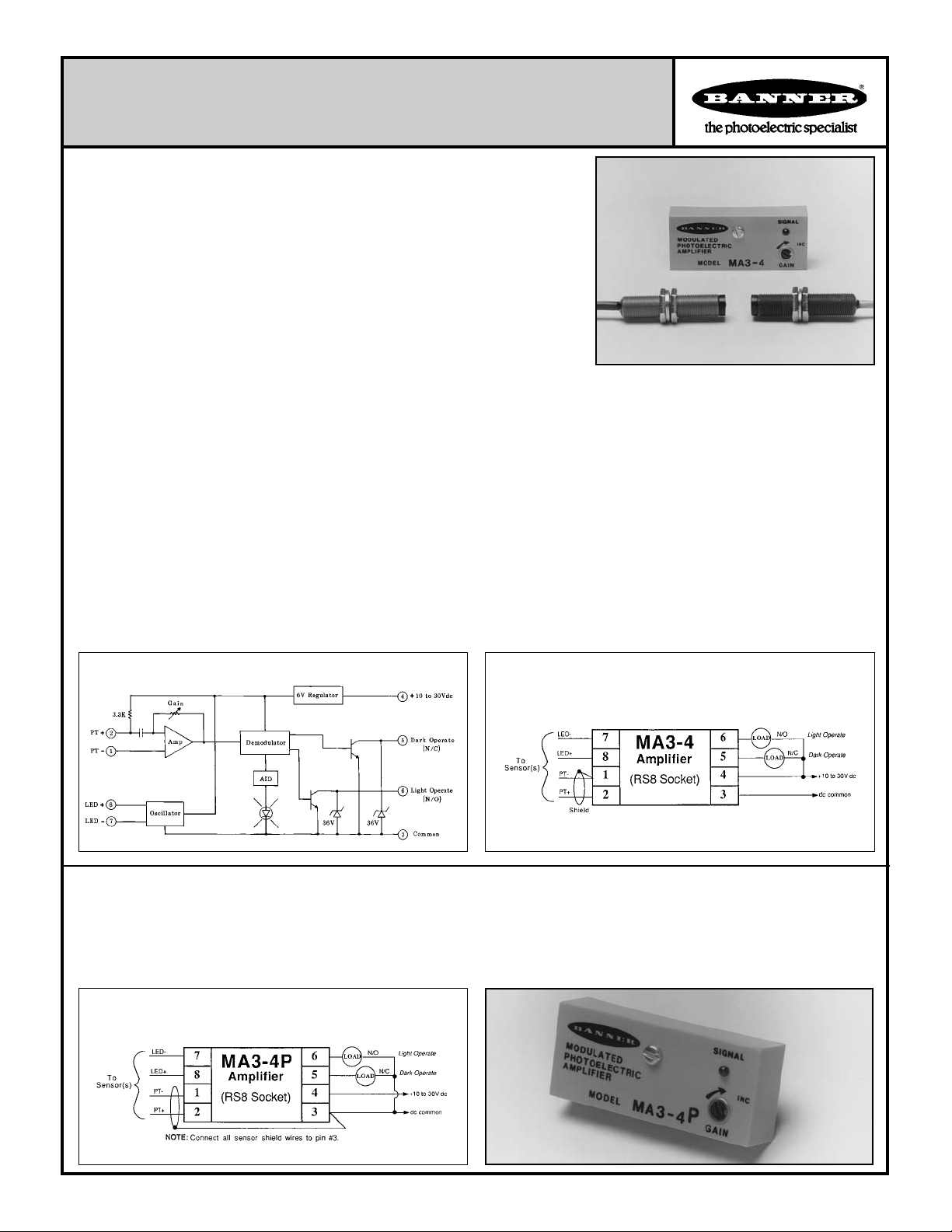
MA3-4 and MA3-4P Modulated Ampliers
Banner MICRO-AMP® module models MA3-4 and MA3-4P are modulated ampli-
ers designed for use with the popular family of Banner high-performance remote
sensors. When these modulated remote sensors are used with the MA3-4 or MA3-4P,
their optical response is the same as when they are used with the larger MAXI-AMP
CM Series modules.
These modules are powered by 10 to 30 volts dc. They feature the patented Banner
Alignment Indicator Device (AID™) signal strength LED. Sensor sensitivity is adjustable via a top-mounted GAIN potentiometer. Circuitry is epoxy-encapsulated and
protected by a tough molded VALOX
modules via the optional RS8 socket/wiring base, or the module may be mounted
directly to a printed circuit board.
The sensors which are used with these modules are totally encapsulated for durability
and innite life. Wide beam angles eliminate alignment problems, and high optical gain permits reliable sensing under severe conditions.
MICRO-AMP MA3-4 Specications
SUPPLY VOLTAGE: 10 to 30V dc at less than 20 milliamps (exclusive of load); 10% maximum ripple.
OUTPUT CONFIGURATION: two open-collector NPN (current
sinking) transistor (solid-state) switches; one normally-open (light
operate) and one normally closed (dark operate). 150 milliamps maximum, each output. Saturation voltage less than 0.5V dc at 10 milliamp
load. Off-state leakage current less than 1 microamp.
RESPONSE SPEED: 1 millisecond ON and OFF.
REPEATABILITY: 0.3 millisecond.
SENSOR LEAD LENGTH: 30 feet (9m) maximum.
®
housing. Connections may be made to these
ADJUSTMENT: GAIN adjustment (single-turn potentiometer; adjust
with small at-blade screwdriver).
INDICATOR: exclusive Banner Alignment Indicator Device (AID™)
system lights a red LED indicator whenever the sensor "sees" its own
modulated light source, and pulses at a rate proportional to the strength
of the received light signal.
CONSTRUCTION: totally encapsulated plug-in package with
molded VALOX® housing. Gold-ashed connection pins.
OPERATING TEMPERATURE:
-40 to +70 degrees C (-40 to +158 degrees F).
Functional Schematic, MA3-4
Hookup Diagram, MA3-4
Model MA3-4P: PNP (current sourcing) output
Model MA3-4P has the same specications and performance as the MA3-4 amplier, except that the MA3-4P has complementary PNP outputs
in place of the MA3-4's NPN conguration.
OUTPUT: two PNP transistors, complementary outputs; one normally open (light operate) and one normally closed (dark operate). 150 milliamps maximum, each output. Saturation voltage less than 1V dc at 10 milliamps. Off-state leakage current less than 1 microamp.
Hookup Diagram, MA3-4P
Printed in USA
P/N 03341F3G
Page 2
Sensors for use with the MA3-4 and MA3-4P Modulated Amplier
Sensors are epoxy-encapsulated and optics are hermetically sealed. Cables are 6 -1/2 feet (2m) long. 30-foot (9m) cables available by special
order.
Models/Dimensions
Excess Gain
Beam Pattern
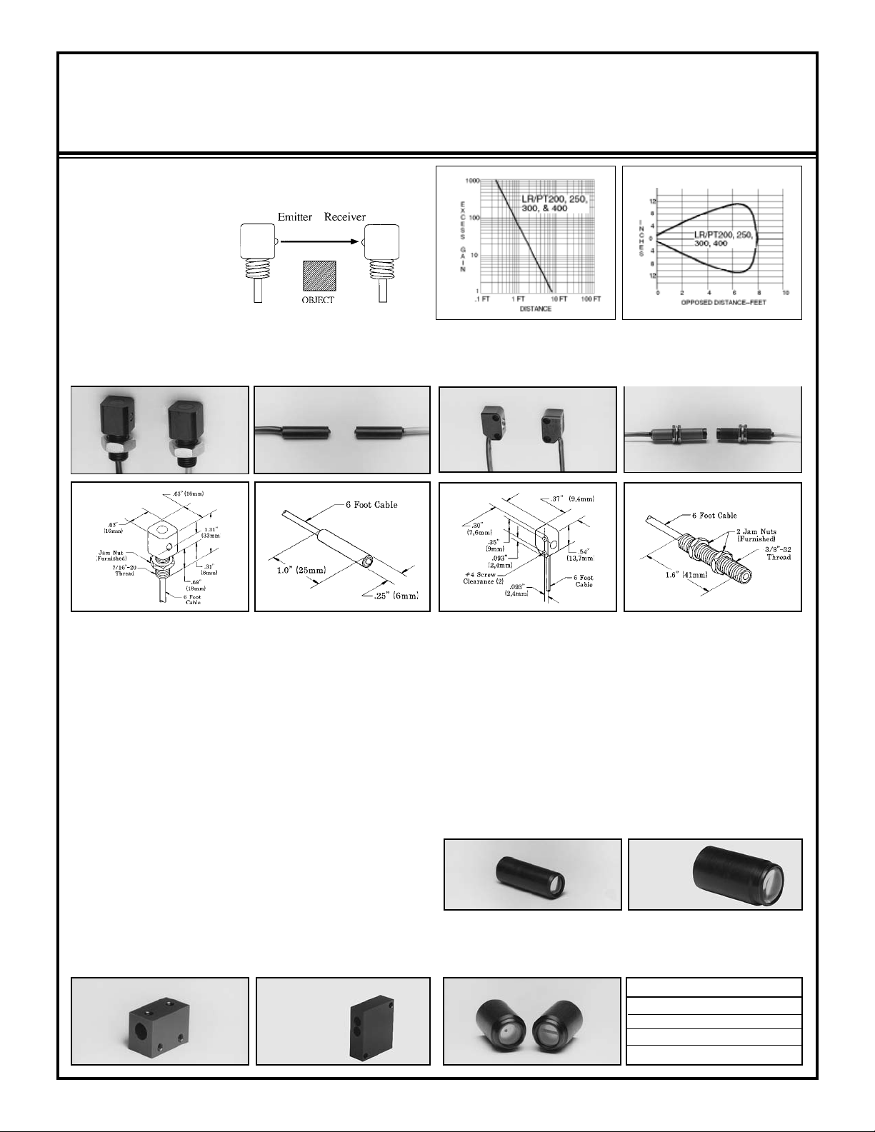
OPPOSED Mode
ALL MODELS
Range: 8 feet (2,4m)
Beam: infrared, 880nm
Effective Beam:
0.14 inch (3,6mm) dia.
PT models are receivers
LR models are emitters
LR200 & PT200
Temp. range: -40 to +100°C
Housing material: black Delrin
LR/PT200, 250, 300, and 400 opposed mode remote sensors are
identical electronically and optically, and differ only in their housings.
All are totally epoxy-encapsulated and use hermetically sealed glass
lenses to eliminate condensation inside the optical chamber. These
sensors may be washed down without damage. Operating temperature
is determined by the type of cable used (see specications above). All
models have a wide beam angle for forgiving line-of-sight alignment.
At the same time, the effective beam of each pair is only 1/8 inch, allowing small-prole resolution and reliable response to fast-moving
objects. LR models are emitters, and PT models are receivers.
LR200 & PT200: this is a right-angle design which mounts through
a 7/16 inch (12mm) diameter hole, using the steel jam nut which is
included. This pair is used most commonly on small conveyors when
it is desireable to run the cable directly down to a wireway.
LR250 & PT250: these sensors feature a 1/4 inch (6,4mm) diameter
smooth barrel design, and are usually held in place in a clearance hole
with a small set-screw. Optional mounting blocks (shown below)
are available. Model SMB250 holds the sensor in place with two
set-screws. The block is then mounted to a bracket (such as model
SMB300), or directly to a machine frame with two #6 screws. Block
model SMB250C holds an LR & PT250 together to converge at approximately 1/2 inch ahead of the block.
SMB250 SMB250C
®
LR250 & PT250 LR300 & PT300 LR400 & PT400
Temp. range: -40 to +100°C
Housing material: black Delrin
®
Temp. range: -40 to +80°C
Housing material: black VALOX
LR & PT300: this is a miniature right-angle design which is mounted
in place using two #4 screws. This pair uses a very exible, low-prole
2-wire cable. Despite their small size, the optical performance of the
LR/PT300 is equal to the other remote sensor pairs.
LR400 & PT400: the 3/8 inch (9,5mm) diameter threaded barrel design makes the LR/PT400 the most versatile and most popular remote
opposed sensor pair. They are easily mounted through clearance holes
using the jam nuts which are supplied. They may be used with optional
L4 or L16 lenses for extended range and/or higher excess gain. The
addition of an L4 lens on both the LR and PT400 will increase their
range from 8 feet to 40 feet and increase the excess gain at any distance
by a factor of 25X. A pair of L16 lenses will increase available excess
gain by a factor of 250X.
L4 lens
The LR/PT400 pair is often used at close range with optional AP400 aperture
assemblies to create a very small and well-dened effective beam for resolving small proles, increasing sensing repeatability, or easing response time
requirements.
AP400 apertures
Temp. range: -40 to +100°C
®
Housing material: anod. aluminum
L16 lens
Aperture model
AP400-010
AP400-015
AP400-040
AP400-030R
Aperture size
.010" dia.
.015" dia.
.040" dia.
.030" x .125"
2
Page 3

Sensors for use with MA3-4 and MA3-4P Modulated Ampliers
Sensors are epoxy-encapsulated. Cables are 6-1/2 feet (2m) long. 30-foot (9m) cables available by special order.
Models/Dimensions
SP300EL & SP300RL
Range: 50 feet (15m)
Effective Beam: .5 inch (13mm)
dia.
Emitter-receiver pair SP300EL/RL are extremely rugged and are totally
encapsulated in anodized aluminum housings. The threaded hub at the cable
exit allows for the use of exible armored cable or protective PVC tubing with
the addition of compression gland model CF7-16. This pair uses collimating
Temp. range: -40 to +100°C
Housing material: anodized
aluminum
SP300L
Range: 15 feet (4,5m)
with BRT-3 retroreector
Temp. range: -40 to +80°C
Housing material: blue anodized
aluminum
Excess Gain Beam Pattern
Long Range
OPPOSED Mode
lenses to increase range. These sensors should also be used at short ranges for
their high excess gain or to avoid optical "crosstalk" in situations which require
several pairs to be mounted adjacent to one another.
RETROREFLECTIVE
Mode
Model SP300L is a remote retroreective sensor with the same rugged design
as the SP300EL/RL, described above. Its useable range is from 6 inches to 15
feet (0,2 to 4,5m) using the model BRT-3 retroreector.
LP400WB
Range: 3 inches (76mm)
Temp. range: -40 to +80°C
Housing material: blue anodized
aluminum
"WB" in this model number designates "wide beam". The LP400WB is an
infrared divergent mode (wide angle diffuse mode) sensor which is particularly
forgiving for reectively sensing transparent or translucent materials or for
DIVERGENT Mode
If the object that is to break the beam has a shiny surface, then the SP300L and
its retroreector should be mounted so that the beam is at an angle of 10 degrees
or more to that surface in order to eliminate false signals which are caused by
proxing.
sensing objects with irregular surfaces (e.g.- webs with "utter"). The optics are
such that even small threads or wires .005" (0,1mm) or greater in diameter may be
detected when they pass within .25" (6mm) of the sensor's plastic lens. Due to its
wide response pattern, the LP400WB should not be used for precise positioning
control, nor should it be mounted with its lens recessed into a hole.
3
Page 4
Sensors for use with MA3-4 and MA3-4P Modulated Ampliers
Sensors are epoxy-encapsulated. Cables are 6-1/2 feet (2m) long. 30-foot (9m) cables available by special order.
Models/Dimensions
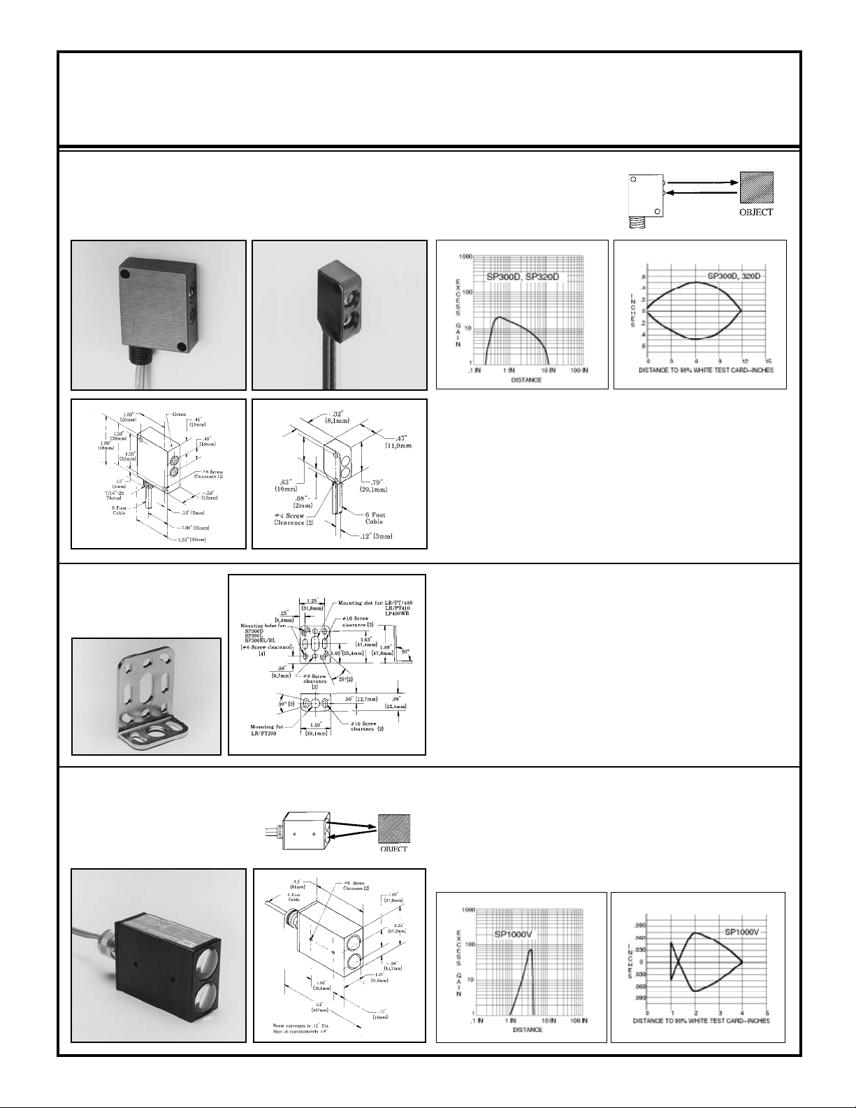
SP300D
Range: 12 inches (30cm) both models
Housing material (SP300D):
green anodized aluminum
SP320D
Temp. range: -40 to +80°C both
models
Housing material (SP320D):
black VALOX
®
Excess Gain Beam Pattern
DIFFUSE
Mode
SP300D: the SP300D is the diffuse mode version of the SP300L with the same
rugged aluminum housing and totally encapsulated construction. The glass
lenses are hermetically sealed, which eliminates any possibility of condensation inside the lenses and allows operation in adverse environments like steam
washdown and high vibration. The SP300D may be mounted by its throughholes or with the SMB300 bracket, as shown below.
SP320D: model SP320D is identical to the SP300D, except for its housing. The
320 is a miniature plastic package, designed to t into very tight locations. It
mounts using two #4 (3mm) screws. The SP320D and the SP300D are excellent
for nearly any presence sensing application.
SMB300
Universal Mounting
Bracket for
SP300 Sensors
SP1000V
Range: focus at 3.8 inches (96mm)
Temp. range: -40 to +80 degrees C
Housing material: black anodized
aluminum
CONVERGENT Mode
Accessory bracket model SMB300 is designed for 2-axis universal
mounting of sensor models SP300EL, SP300RL, SP300L, and SP300D.
These sensors are afxed to the SMB300 with two #6 (3,5mm) screws.
The bracket, in turn, mounts with two #10 (5mm) screws.
In addition, as indicated by the dimension drawing, the SMB300 has a
clearance slot for mounting LR400, PT400, and LP400WB barrel sensors. LR & PT200 sensors may be mounted with the SMB300, using
its 7/16-20 threaded hole and steel jam nut, which is supplied with the
sensors. LR250 and PT250 sensors may be used with the SMB300 when
the SMB250 block is used. Also, two SMB250 blocks may be attached
to the SMB300 bracket and angled to mechanically converge an LR &
PT250 sensor pair.
The SP1000V is a convergent mode sensor that produces a very small 0.1
inch (2,5mm) diameter sensing image at a point exactly 3.8 inches (96mm)
from its glass lenses. As the excess gain curve illustrates, the SP1000V has a
very sharp drop-off of gain beyond the focus point. This feature makes it an
excellent choice for detecting a small part which is only a fraction of an inch
in front of another surface, such as parts on a conveyor (viewed from above).
It is also ideal for ll level detection and for precise positioning control, in
lieu of opposed sensing.
4
Page 5
Sensors for use with MA3-4 and MA3-4P Modulated Ampliers
Sensors are epoxy-encapsulated and optics are hermetically sealed. Cables are 6-1/2 feet (2m) long. 30-foot (9m) cables available by special
order.
Excess GainModels/Dimensions
Beam Pattern
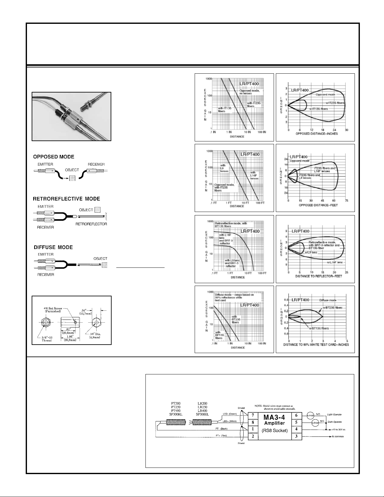
FIBER OPTIC Mode
glass ber optics
LR400 & PT400
with FOF-400 ttings
and ber optics
Range: see excess gain curves
Temp. range: -40 to +100°C
The threaded barrel design of the
LR400 and PT400 permit the connection of any Banner glass ber
optic assembly by using two model
FOF-400 ttings. The sensors are
typically mounted through a 3/8
inch (10mm) diameter clearance
hole, with the FOF-400 fittings
threaded onto them after mounting. Setscrews in the ttings lock
the bers in place, but allow rapid
replacement without disturbing any
electrical wiring.
As the excess gain curves show, the
LR/PT400 combination produces a
high-performance ber optic sensing system. With the amplier's
1 millisecond response time, this
system can be used for almost any
ber optic requirement.
Fiber optic information:
IT13S: individual assembly .06 in.
(1,5mm) dia. bundle
IT23S: individual assembly .12 in.
(3mm) dia. bundle
FOF-400 ber optic tting
BT13S:bifurcated assembly .06 in.
(1,5mm) dia. bundle
BT23S:bifurcated assembly .12 in.
(3mm) dia. bundle
L9: .5 in. (12mm) dia. lens
L16F: 1.0 in. (25mm) dia. lens
Sensor Hookup Diagrams for MA3-4 MICRO-AMP Modules (continued on
page 6)
The following hookup diagrams include all of the
remote sensors for use with the model MA3-4
modulated amplier module. It is important to
note how the shield wire of a remote sensor is
wired. The shield wire is the uninsulated wire
in each sensor cable. Failure to connect the
shield as shown may result in false operation of
the amplier. When wiring emitters, it is good
practice to connect the positive wire rst. LEDs
are sensitive to application of the wrong voltage,
and can easily be destroyed.
Hookup of LR/PT200, 250, 300, and 400
NOTE: only one sensor may be connected to
each MA3-4 amplier.
NOTE: Shield wires must be connected as shown to avoid cable crosstalk.
5
Page 6
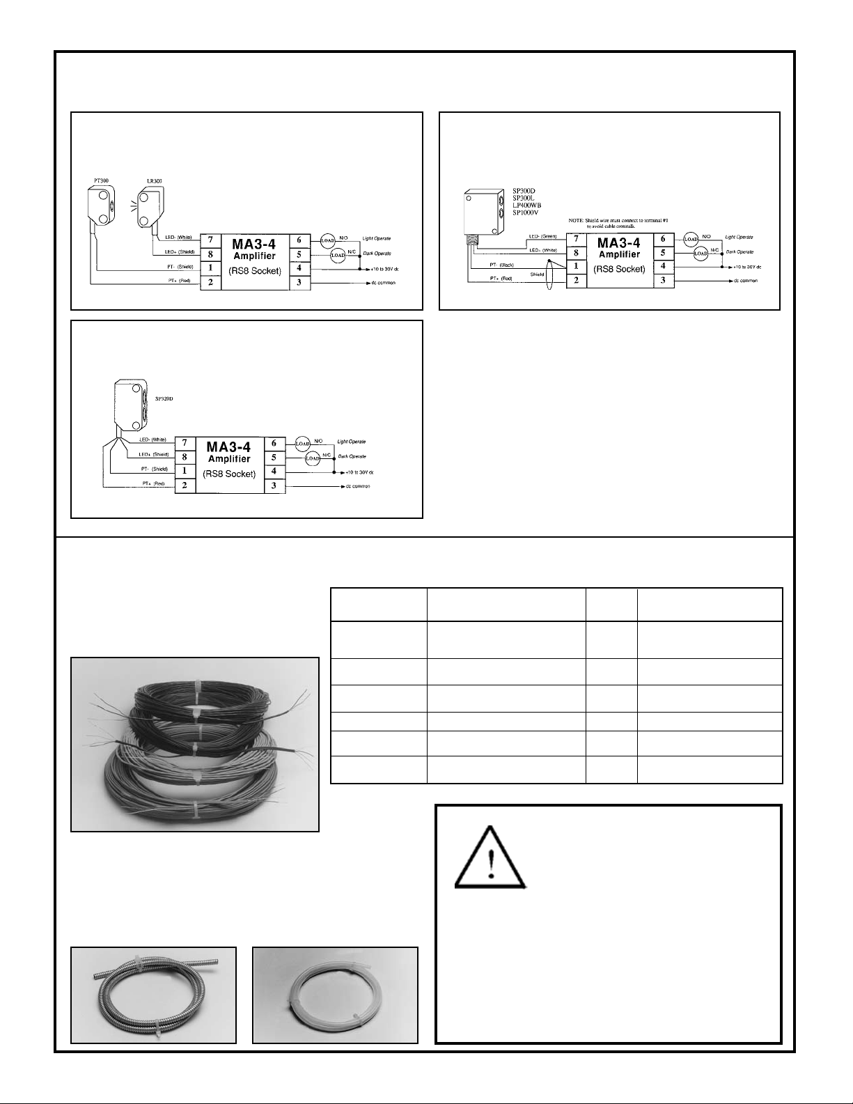
Sensor Hookup Diagrams for MA3-4 MICRO-AMP Modules (continued)
Hookup of LR300 and PT300 Hookup of SP300D, SP300L, LP400WB, SP1000V
Hookup of SP320D
IMPORTANT : Cable Splicing Information
Remote sensor cables may be run up to 30 feet (9m) away from the MA3-4
amplier. All sensor models are available from the factory with 30 feet of
cable, installed as an option.
When splicing additional cable to the standard 6-1/2 foot length, it is
important to use a separate shielded cable for emitter and receiver wires.
Combining emitter and receiver wires together in the same cable (even if
the cable is shielded) will result in direct coupling of the emitter signal to
the receiver leads.
This is called "cable crosstalk" and will not allow full amplier sensitivity
setting without an amplier "lock on" situation, which appears as a continuous LIGHT condition. Banner offers 100 foot (30m) lengths of sensor
extension cable (see below) which, if used for cable splicing, will minimize
the chances for cable crosstalk.
Accessories for High Performance Modulated Remote Sensors
Extension Cable
Modulated remote sensors require specially
designed cable for efcient sensor performance.
Extension cable is available in 100 foot (30m)
lengths.
Extension Cable
Model
ESC-100
RSC-100
SSC-100
EC300E-100
EC300R-100
EC320-100
Used on Sensor Models
LR200, LR250, LR400,
SP300EL
PT200, PT250, PT400,
SP300RL
SP300D, SP300L, LP400WB,
SP1000V
LR300
PT300
SP320D
# of
Wires
3
3
5
2
2
4
White, Green, Shield
Red, Black, Shield
White, Green, Red, Black,
Shield
White, Shield
Red, Shield
White, Shield, Red, Shield
Wire Colors
Cable Protection
AC-6 6 feet (1,8m)
AC-30 30 feet (9m)
This is mild-steel exible tubing
used with the compression ttings, at
right, to achieve maximum protection
to sensor cables.
I.D. = 5/16"; O.D. = 7/16".
PVC-6 6 feet (1,8m)
PVC-30 30 feet (9m)
Heavy duty PVC tubing used to
protect sensor cable in applications
involving moisture and/or corrosive
materials. I.D. = 1/4"; O.D. = 3/8".
WARNING MICRO-AMP
include the self-checking redundant circuitry necessary to allow their use in personnel safety applications. A sensor or amplier failure or malfunction
can result in either an energized or a de-energized
output condition.
Never use this product as a sensing device for personnel protection. Its
use as a safety device may create an unsafe condition which could lead
to serious injury or death.
Only MACHINE-GUARD and PERIMETER-GUARD Systems, and
other systems so designated, are designed to meet OSHA and ANSI
machine safety standards for point-of-operation guarding devices. No
other Banner sensors or controls are designed to meet these standards, and
they must NOT be used as sensing devices for personnel protection.
®
Systems do NOT
Banner Engineering Corp. 9714 10th Avenue No., Minneapolis, MN 55441 Telephone: (763) 544-3164 FAX (applications): (763) 544-3573
 Loading...