

Page 1
OPPOSED
P
POLAR RETRO
DIFFUSE
FIXED-FIELD
1
10
100
1 m
3.3 ft
10 m
33 ft
100 m
330 ft
.1 m
.33 ft
1000
E
X
C
E
S
S
G
A
I
N
DISTANCE
M18 Series
Opposed Mode
25 m
82 ft
20 m
66 ft
15 m
49 ft
10 m
32 ft
5 m
16 ft
0
0
500 mm
1000 mm
1500 mm
500 mm
1000 mm
1500 mm
0
20 in
40 in
60 in
20 in
40 in
60 in
DISTANCE
M18 Series
Opposed Mode
EZ-BEAM M18 Series Sensors
0 049201 8
Stainless steel 18mm barrel-style dc photoelectric sensors
• 18 mm threaded-barrel sensor
• 10 to 30V dc; choose SPDT (complementary) NPN or PNP outputs (150 mA max.
ea.)
• Easy to use; no adjustments are necessary
• Advanced self-diagnostics with separate alarm output*; dual LED system indicates
sensor performance
• Choice of integral cable or Euro-style quick disconnect connector
• Completely epoxy-encapsulated to provide superior durability, designed to meet rigorous IP69K standards for use in high pressure washdowns
• Brackets available for a wide array of mounting options
* U.S. patent 5087838 (see Specifications)
WARNING: Not To Be Used for Personnel Protection
Never use this device as a sensing device for personnel protection. Doing so could lead to serious
injury or death. This device does NOT include the self-checking redundant circuitry necessary to allow its
use in personnel safety applications. A sensor failure or malfunction can cause either an energized or deenergized sensor output condition.
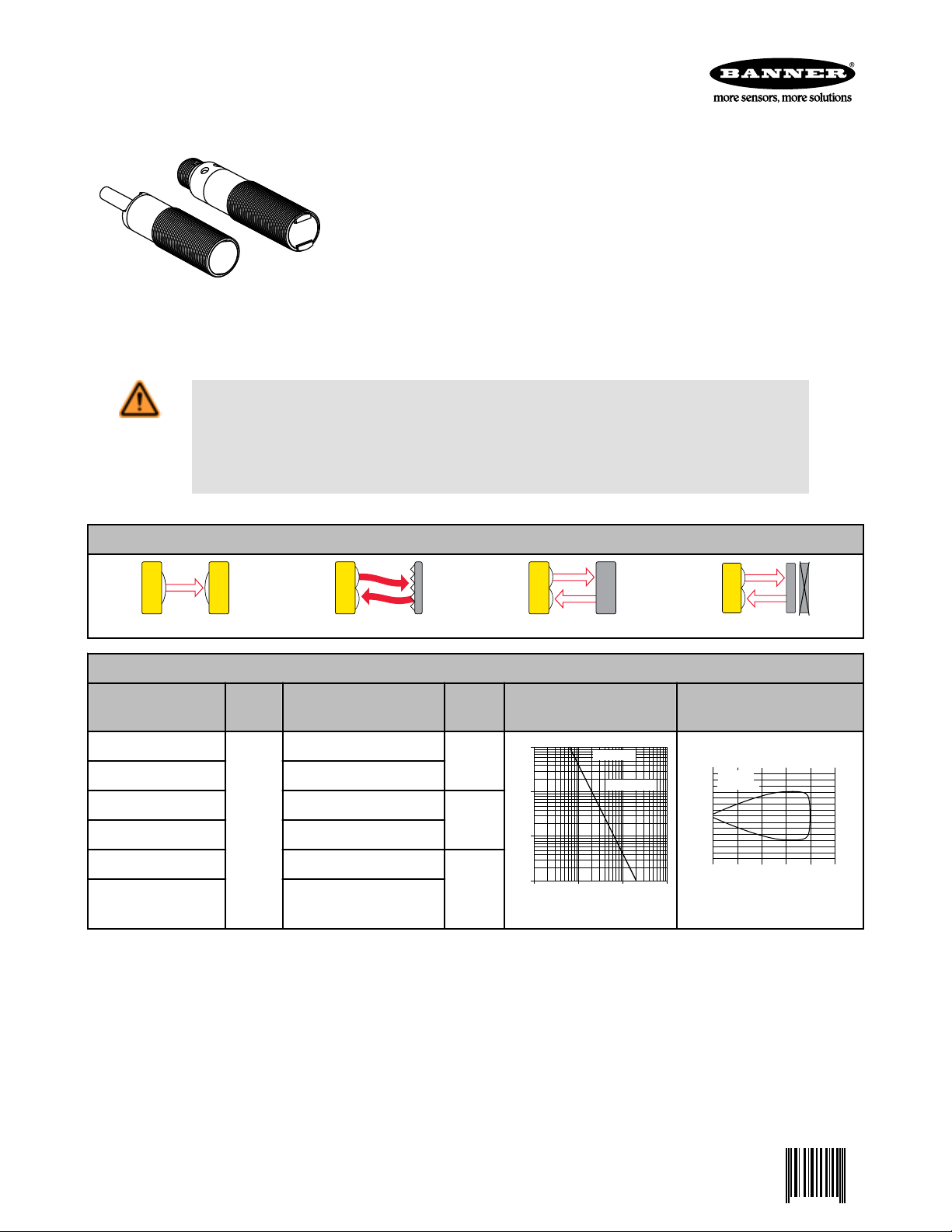
EZ-BEAM M18 Series Sensing Mode Options
M18 Series Opposed-Mode Emitter (E) and Receiver (R)
Models (Infrared,
950 nm)
M186E
Range Cable
2 m (6.5')
Output
Type
Excess Gain Beam Pattern
-
M186EQ 4-Pin Euro-style QD
M18SN6R 2 m (6.5')
M18SN6RQ 4-Pin Euro-style QD
(66')
20 m
NPN
M18SP6R 2 m (6.5')
PNP
M18SP6RQ 4-Pin Euro-style QD
Standard 2 m (6.5 ft) cable models are listed. To order the 9 m (30 ft) cable model, add suffix "W/30" (M18SN6R W/30). Models with a
QD connector require a mating cable.
P/N 049201 Rev. C 1/14/2013
Page 2
1
10
100
.1 m
.33 ft
1 m
3.3 ft
10 m
33 ft
.01 m
.033 ft
1000
E
X
C
E
S
S
G
A
I
N
DISTANCE
M18 Series
Non-Polarized Retro
with BRT-3 Reflector
2.5 m
8.0 ft
2.0 m
6.4 ft
1.5 m
4.8 ft
1.0 m
3.2 ft
.5 m
1.6 ft
0
0
40 mm
80 mm
120 mm
40 mm
80 mm
120 mm
0
1.6 in
3.2 in
4.7 in
1.6 in
3.2 in
4.7 in
DISTANCE
M18 Series
Non-Polarized Retro
with BRT-3 Reflector
1
10
100
.1 m
.33 ft
1 m
3.3 ft
10 m
33 ft
.01 m
.033 ft
1000
E
X
C
E
S
S
G
A
I
N
DISTANCE
M18 Series
Polarized Retro
with BRT-3 Reflector
2.5 m
8.0 ft
2.0 m
6.4 ft
1.5 m
4.8 ft
1.0 m
3.2 ft
.5 m
1.6 ft
0
0
50 mm
100 mm
150 mm
50 mm
100 mm
150 mm
0
2 in
4 in
6 in
2 in
4 in
6 in
DISTANCE
M18 Series
Polarized Retro
with BRT-3 Reflector
1
10
100
10 mm
.4 in
100 mm
4 in
1000 mm
40 in
1 mm
.04 in
1000
E
X
C
E
S
S
G
A
I
N
DISTANCE
M18 Series
Short Range
Diffuse Mode
Maximum Gain
Minimum Gain
125 mm
5 in
100 mm
4 in
75 mm
3 in
50 mm
2 in
25 mm
1 in
0
0
5 mm
10 mm
15 mm
5 mm
10 mm
15 mm
0
0.2 in
0.4 in
0.6 in
0.2 in
0.4 in
0.6 in
DISTANCE
M18 Series
Short Range Diffuse
1
10
100
10 mm
.4 in
100 mm
4 in
1000 mm
40 in
1 mm
.04 in
1000
E
X
C
E
S
S
G
A
I
N
DISTANCE
M18 Series
Long Range
Diffuse Mode
Maximum Gain
Minimum Gain
400 mm
15 in
320 mm
12 in
240 mm
9 in
160 mm
6 in
80 mm
3 in
0
0
5 mm
10 mm
15 mm
5 mm
10 mm
15 mm
0
0.2 in
0.4 in
0.6 in
0.2 in
0.4 in
0.6 in
DISTANCE
M18 Series
Long Range Diffuse
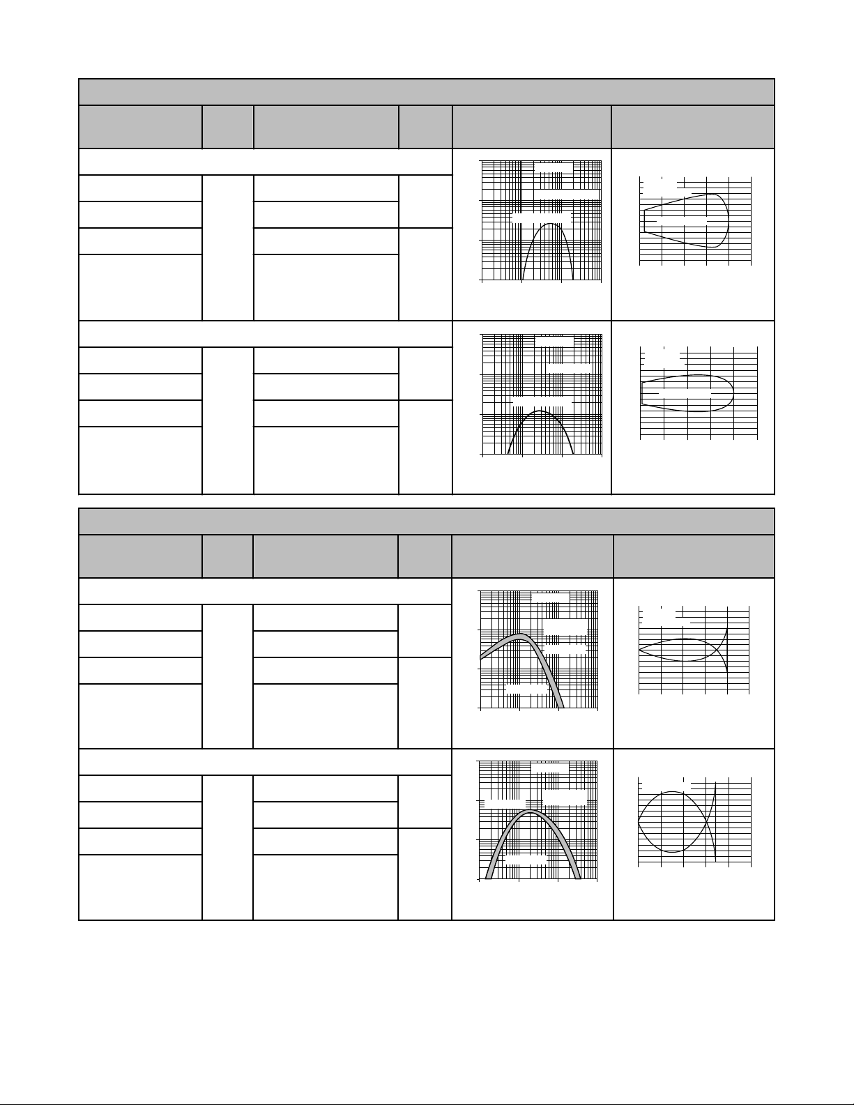
EZ-BEAM M18 Series Sensors
M18 Series Retroreflective Mode
Models Range Cable
Non-Polarized (Infrared, 950 nm)
M18SN6L
2 m (6.5')
M18SN6LQ 4-Pin Euro-style QD
M18SP6L 2 m (6.5')
2 m
(79")
M18SP6LQ 4-Pin Euro-style QD
Polarized (Visible red, 680 nm)
M18SN6LP
2 m (6.5')
M18SN6LPQ 4-Pin Euro-style QD
M18SP6LP 2 m (6.5')
2 m
(79")
M18SP6LPQ 4-Pin Euro-style QD
M18 Series Diffuse Mode (Infrared, 880 nm)
Output
Type
NPN
PNP
NPN
PNP
Excess Gain Beam Pattern
Models Range Cable
Output
Type
Excess Gain Beam Pattern
100 mm Range
M18SN6D
2 m (6.5')
NPN
M18SN6DQ 4-Pin Euro-style QD
M18SP6D 2 m (6.5')
100 mm
(4")
PNP
M18SP6DQ 4-Pin Euro-style QD
300 mm Range
M18SN6DL
2 m (6.5')
NPN
M18SN6DLQ 4-Pin Euro-style QD
M18SP6DL 2 m (6.5')
300 mm
(12")
PNP
M18SP6DLQ 4-Pin Euro-style QD
2 www.bannerengineering.com - tel: 763-544-3164 P/N 049201 Rev. C
Page 3
1
10
100
1 mm
.04 in
10 mm
.4 in
100 mm
4 in
.1 mm
.004 in
E
X
C
E
S
S
G
A
I
N
DISTANCE
1000
M18 Series
Fixed-field mode
with 25 mm far
limit cutoff
1
10
100
1 mm
.04 in
10 mm
.4 in
100 mm
4 in
.1 mm
.004 in
E
X
C
E
S
S
G
A
I
N
DISTANCE
1000
M18 Series
Fixed-field mode
with 50 mm far
limit cutoff
1
10
100
1 mm
.04 in
10 mm
.4 in
100 mm
4 in
.1 mm
.004 in
E
X
C
E
S
S
G
A
I
N
DISTANCE
1000
M18 Series
Fixed-field mode
with 100 mm far
limit cutoff
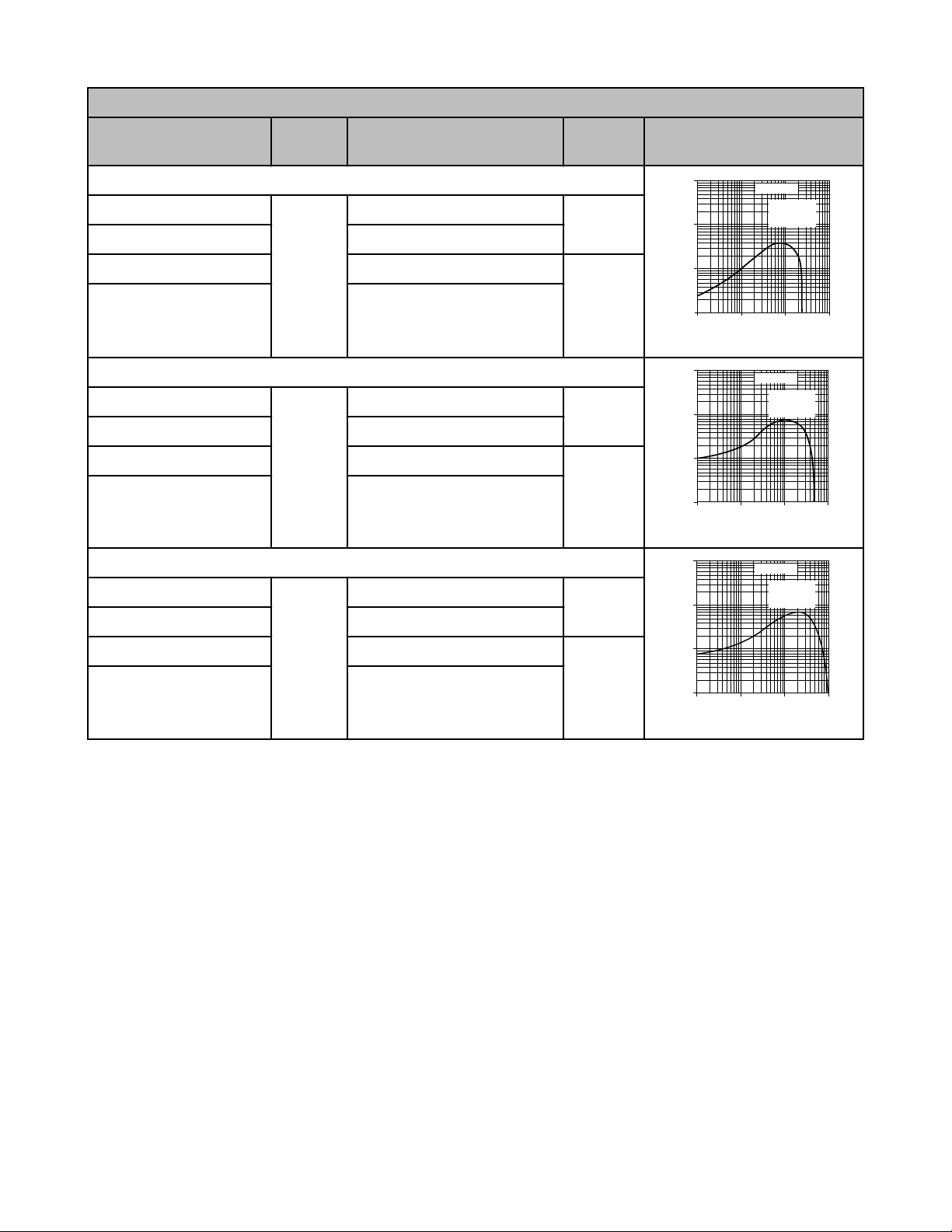
EZ-BEAM M18 Series Sensors
M18 Fixed-Field Mode
Models
Cutoff
Point
Cable
with 25 mm far limit cutoff
M18SN6FF25
2 m (6.5')
M18SN6FF25Q 4-Pin Euro-style QD
M18SP6FF25 2 m (6.5')
25 mm (1")
M18SP6FF25Q 4-Pin Euro-style QD
with 50 mm far limit cutoff
M18SN6FF50
2 m (6.5')
M18SN6FF50Q 4-Pin Euro-style QD
M18SP6FF50 2 m (6.5')
50 mm (2")
M18SP6FF50Q 4-Pin Euro-style QD
with 100 mm far limit cutoff
Output
Type
NPN
PNP
NPN
PNP
Excess Gain
M18SN6FF100
2 m (6.5')
NPN
M18SN6FF100Q 4-Pin Euro-style QD
M18SP6FF100 2 m (6.5')
100 mm
(4")
PNP
M18SP6FF100Q 4-Pin Euro-style QD
The excess gain curves above show excess gain vs. sensing distance for M18 Series fixed-field sensors with 25-, 50- and 100-millimeter
cutoffs. Maximum excess gain for the 25-mm models occurs at a lens-to-object distance of about 7 mm; for the 50-mm models, at about
10 mm; and for the 100-mm models, at about 20 mm. Sensing at or near these distances will make maximum use of each sensor’s
available sensing power. Backgrounds and background objects must always be placed beyond the cutoff distance.
These excess gain curves were generated using a white test card of 90% reflectance. Objects with reflectivity of less than 90% reflect
less light back to the sensor, and thus require proportionately more excess gain in order to be sensed with the same reliability as more
reflective objects. When sensing an object of very low reflectivity, it may be important to sense it at or near the distance of maximum
excess gain.
The effects of object reflectivity on cutoff distance, though small, may be important for some applications. Sensing of objects of less than
90% reflectivity causes the cutoff distances to be “pulled” slightly closer to the sensor. For example, an excess gain of 1 for an object that
reflects 1/10 as much light as the 90% white card is represented by the heavy horizontal graph line at excess gain = 10. An object of this
reflectivity results in far limit cutoffs of approximately 20, 40 and 70 mm (for 25-, 50- and 100-mm cutoff models, respectively).
Objects with reflectivity greater than 90% return more light to the sensor. For this reason, highly reflective backgrounds or background
objects such as mirrors, polished metal, and other sources of specular reflections require special consideration. To use a highly reflective
background, place it as far beyond the cutoff distance as possible and angle it to direct reflected light away from the sensor.
EZ-BEAM M18 Series Fixed-Field Sensor Setup Tips
For highest sensitivity, the sensor-to-object distance should be such that the object will be sensed at or near the point of maximum excess gain. The background must be placed beyond the cutoff distance. Following these two guidelines makes it possible to detect objects
of low reflectivity, even against close-in reflective backgrounds.
P/N 049201 Rev. C www.bannerengineering.com - tel: 763-544-3164 3
Page 4

Sensing
Axis
R2
R1
E
E
R2
R1
E = Emitter
R1 = Near Detector
R2 = Far Detector
M18FF Sensor
Core of
Emitted
Beam
Cutoff
Distance
Reflective
Background
Strong
Direct
Reflection
to R1
Fixed Sensing
Field
E
R2
R1
E = Emitter
R1 = Near Detector
R2 = Far Detector
M18FF Sensor
Core of
Emitted
Beam
Cutoff
Distance
Reflective
Background
Strong
Direct
Reflection
Away From
Sensor
Fixed Sensing
Field
E
R2
R1
E = Emitter
R1 = Near Detector
R2 = Far Detector
Area of R1 Response
Area of R2 Response
Area of R1 and R2 Response
Reflective
Background or
Moving Object
M18FF Sensor
Cutoff
Distance
Fixed Sensing
Field
R1 Response
R2 Response
E, R2, R1
E = Emitter
R1 = Near Detector
R2 = Far Detector
Area of R1 and R2 Response
M18FF Sensor
Reflective
Background
or Moving
Object
Cutoff
Distance
Fixed Sensing
Field
EZ-BEAM M18 Series Sensors
In the drawings and discussion, E, R1, and R2 identify how the sensor’s three optical elements (Emitter “E”, Near Detector “R1”, and Far
Detector “R2”) line up across the face of the sensor. In figures Reflective Background - Problem, Reflective Background - Solution, and
Object Beyond Cutoff - Problem, these elements align vertically; in Object Beyond Cutoff - Solution, they align horizontally. Note how the
position of the tabs on the front of the sensor helps to define the sensing axis of the sensor (Sensing Axis). The sensing axis becomes
important in situations like those illustrated in the Object Beyond Cutoff figures.
Sensing Axis. Reflective Background - Problem Reflective Background - Solution
As a general rule, the most reliable sensing of an object approaching from the side occurs when the line of approach is parallel to the
sensing axis.
Background Reflectivity and Placement. Avoid mirror-like backgrounds that produce specular reflections. False sensor response will
occur if a background surface reflects the sensor’s light more strongly to the near detector (R1) than to the far detector (R2). The result is
a false ON condition (Reflective Background - Problem). Use of a diffusely-reflective (matte) background will cure this problem. Other
possible solutions are to either angle the sensor or angle the background (in any plane) so that the background does not reflect back to
the sensor (Reflective Background - Solution).
An object beyond the cutoff distance, either moving or stationary (and when positioned as shown in Object Beyond Cutoff - Problem), can
cause unwanted triggering of the sensor because it reflects more light to the near detector than to the far detector. Remedy the problem
easily by rotating the sensor 90° (Object Beyond Cutoff - Solution) to align the sensing axis horizontally. The object then reflects the R1
and R2 fields equally, resulting in no false triggering. A better solution, if possible, may be to reposition the object or the sensor.
Unwanted triggering of the sensor from an object beyond the cutoff can also be caused by attempting to sense a small object moving
perpendicular to the sensor face, or by an object moving through the off-center position shown. Making the object larger, centering the
sensor relative to the object, or rotating the sensor to place the sensing axis perpendicular to the longer dimension of the object (Object
Beyond Cutoff - Solution) will solve the problem.
4 www.bannerengineering.com - tel: 763-544-3164 P/N 049201 Rev. C
Object Beyond Cutoff - Problem Object Beyond Cutoff - Solution
Page 5

EZ-BEAM M18 Series Sensors
Specifications
General
Supply Voltage
10 to 30V dc (10% maximum ripple)
Supply Current (Exclusive of Load Current)
Diffuse: 25 mA
Fixed-field: 35 mA
Opposed Mode Emitters: 25 mA
Opposed Mode Receivers: 20 mA
Retro, Non-polarized: 25 mA
Retro, Polarized: 30 mA
Supply Protection Circuitry
Protected against reverse polarity and transient voltages
Outputs
Configuration
SPDT (complementary) solid-state dc switch; choose
NPN (current sinking) or PNP (current sourcing) models.
Light operate: Normally open output conducts when the
sensor sees its own (or the emitter’s) modulated light
Dark operate: Normally closed output conducts when
the sensor sees dark; the normally closed output may
be wired as a normally open alarm output, depending
upon hookup to the power supply (U.S. patent
5087838)
Output Rating
150 mA maximum (each) in standard hookup; When
wired for alarm output, the total load may not exceed
150 mA
OFF-State Leakage Current: < 1 microamp at 30V dc
ON-State Saturation Voltage: < 1V at 10 mA dc; < 1.5V
at 150 mA dc
Indicators
Two LEDs (green and yellow)
Green glowing steadily: power to sensor is ON
Green flashing: output is overloaded
Yellow glowing steadily: normally open output is con-
ducting
Yellow flashing: excess gain marginal (1-1.5x) in light
condition
Construction
Housings: Stainless Steel
Lenses: Lexan® (opposed models) or acrylic
Connections
2 m (6.5') or 9 m (30') attached cable, or 4-pin Eurostyle quick disconnect fitting
Output Protection Circuitry
Protected against false pulse on power-up and continuous overload or short circuit of outputs
Output Response Time
Opposed mode: 3 milliseconds ON, 1.5 milliseconds
OFF
Polarized Retro, Non-polarized Retro, Fixed-field, and
Diffuse: 3 milliseconds ON and OFF
NOTE: 100 millisecond delay on power-up; outputs do
not conduct during this time
Repeatability
Opposed mode: 375 microseconds
Polarized Retro, Non-Polarized Retro, Fixed-field and
Diffuse modes: 750 microseconds
Repeatability and response are independent of signal
strength
Environmental
Rating
Leakproof design rated NEMA 6P, IP69K* (DIN 40050)
Vibration and Mechanical Shock
All models meet Mil. Std. 202F requirements.
Method 201A (Vibration; frequency 10 to 60 Hz, max.,
double amplitude 0.06" acceleration 10G).
Method 213B conditions H&I (Shock: 75G with unit op-
erating; 100G for non-operation)
* Cabled models meet IP69K if the cable is protected from highpressure spray
P/N 049201 Rev. C www.bannerengineering.com - tel: 763-544-3164 5
Operating Conditions
Temperature: -40° to +70°C (-40° to 158°F)
Maximum relative humidity: 90% at 50°C (non-con-
densing)
Page 6

59.2 mm*
(2.33")
Yellow LED
output indicator
37.0 mm
(1.46")
Jam nuts
(2 provided)
18 x 1 mm
thread
2 m
(6.5') Cable
Green LED
power indicator
78.0 mm*
(3.07")
Yellow LED
output indicator
Green LED
power indicator
bu
bn
-
+
bk
wh
Load
Load
Load
Load
10-30V dc
bn
bu
−
+
bk
wh
Load
Load
10-30V dc
bn
bu
+
−
10-30V dc
10-30V dc
bu
bn
−
+
bk
wh
Alarm
Load
10-30V dc
bn
bu
−
+
bk
wh
Alarm
Load
78.0 mm*
(3.07")
Yellow LED
output indicator
Green LED
power
indicator
44 Typ.
ø 14.5
M12 x 1
2
3
4
1
EZ-BEAM M18 Series Sensors
EZ-BEAM M18 Series Dimensions
Models with Attached Cable Models with Quick Disconnect
* Polarized retroreflective and fixed-field cabled models = 65.0 mm
(2.56")
* Polarized retroreflective and fixed-field QD models = 83.8 mm
(3.30")
EZ-BEAM M18 Series Wiring Connections
Sensors with NPN (Sinking) Outputs Sensors with PNP (Sourcing) Outputs
Standard Connection for Attached Cable and Quick Disconnect Models
Sensors with NPN (Sinking) Outputs Sensors with PNP (Sourcing) Outputs DC Emitters with Quick Disconnect (no
Alarm Connection for Attached Cable and Quick Disconnect Models
Emitters with Attached Cable
connection to bk and wh wires of QD cable)
Accessories
Cordsets
4-Pin Threaded M12/Euro-Style Cordsets
Straight
Model Length Style Dimensions Pinout
MQDC-406 1.83 m (6 ft)
MQDC-415 4.57 m (15 ft)
MQDC-430 9.14 m (30 ft)
6 www.bannerengineering.com - tel: 763-544-3164 P/N 049201 Rev. C
Page 7

32 Typ.
[1.26"]
30 Typ.
[1.18"]
ø 14.5 [0.57"]
M12 x 1
30
41
46
A
B
C
EZ-BEAM M18 Series Sensors
4-Pin Threaded M12/Euro-Style Cordsets
Model Length Style Dimensions Pinout
MQDC-450
15.2 m (50 ft)
MQDC-406RA 1.83 m (6 ft)
MQDC-415RA 4.57 m (15 ft)
MQDC-430RA 9.14 m (30 ft)
Right-Angle
MQDC-450RA 15.2 m (50 ft)
Mounting Brackets
SMB18A
• Right-angle mounting bracket with a curved slot for versatile
orientation
• 12-ga. stainless steel
• 18 mm sensor mounting hole
• Clearance for M4 (#8) hardware
Hole center spacing: A to B = 24.2
Hole size: A = ø 4.6, B = 17.0 x 4.6, C = ø 18.5
SMB18C
• 18 mm split clamp, black thermoplastic polyester
• Stainless steel mounting hardware included
1 = Brown
2 = White
3 = Blue
4 = Black
A = ø ##.# mm
Hole size: B = ø ##.#
SMB18SF
• 18 mm swivel bracket with M18 x 1 internal thread
• Black thermoplastic polyester
• Stainless steel swivel locking hardware included
Hole center spacing: A = 36.0
Hole size: A = ø 5.3, B = ø 18.0
SMB18UR
• 2-piece universal swivel bracket
• 300 series stainless steel
• Stainless steel swivel locking hardware included
• Mounting hole for 18 mm sensor
Hole center spacing: A = 25.4, B = 46.7
Hole size: B = 6.9 x 32.0, C = ø 18.3
P/N 049201 Rev. C www.bannerengineering.com - tel: 763-544-3164 7
Page 8

68
57
78
A
B
NOTE: Aperture adds 3/16" to sensor length.
Aperture styles
Round Rectangular
Aperture
(Rectangular type shown)
Lens
Housing
12.7 mm
(0.50")
O-ring (2)
22.4 mm
(0.88")
Outside Diameter
EZ-BEAM M18 Series Sensors
SMB30SK
• Flat-mount swivel bracket with extended range of motion
• Black reinforced thermoplastic polyester and 316 stainless
steel
• Stainless steel swivel locking hardware included
Hole center spacing: A = 50.8
Hole size: A = ø 7, B = ø 18
Aperture Kits
AP18SC
Kit includes round apertures of 0.5 mm (0.02"), 1.0 mm (0.04"), and 2.5 mm (0.10") diameter. Each kit also includes a thread-on aperture housing, a Teflon FEP® lens, and two 0rings.
Used with S18, M18.
AP18SR
Kit includes rectangular apertures of 0.5 mm (0.02") wide, 1.0 mm (0.04") wide, and 2.5 mm
(0.10") wide. Each kit also includes a thread-on aperture housing, a Teflon FEP® lens, and
two 0-rings.
Used with S18, M18.
Banner Engineering Corp Limited Warranty
Banner Engineering Corp. warrants its products to be free from defects in material and workmanship for one year following the date of
shipment. Banner Engineering Corp. will repair or replace, free of charge, any product of its manufacture which, at the time it is returned
to the factory, is found to have been defective during the warranty period. This warranty does not cover damage or liability for misuse,
abuse, or the improper application or installation of the Banner product.
THIS LIMITED WARRANTY IS EXCLUSIVE AND IN LIEU OF ALL OTHER WARRANTIES WHETHER EXPRESS OR IMPLIED (INCLUDING, WITHOUT LIMITATION, ANY WARRANTY OF MERCHANTABILITY OR FITNESS FOR A PARTICULAR PURPOSE), AND
WHETHER ARISING UNDER COURSE OF PERFORMANCE, COURSE OF DEALING OR TRADE USAGE.
This Warranty is exclusive and limited to repair or, at the discretion of Banner Engineering Corp., replacement. IN NO EVENT SHALL
BANNER ENGINEERING CORP. BE LIABLE TO BUYER OR ANY OTHER PERSON OR ENTITY FOR ANY EXTRA COSTS, EXPENSES, LOSSES, LOSS OF PROFITS, OR ANY INCIDENTAL, CONSEQUENTIAL OR SPECIAL DAMAGES RESULTING FROM ANY
PRODUCT DEFECT OR FROM THE USE OR INABILITY TO USE THE PRODUCT, WHETHER ARISING IN CONTRACT OR WARRANTY, STATUTE, TORT, STRICT LIABILITY, NEGLIGENCE, OR OTHERWISE.
Banner Engineering Corp. reserves the right to change, modify or improve the design of the product without assuming any obligations or
liabilities relating to any product previously manufactured by Banner Engineering Corp.
www.bannerengineering.com - tel: 763-544-3164
 Loading...