

Page 1
MULTI-BEAM®LS10 Light Screen System
For Sensing Small Parts at High Speeds
Printed in USA 05/08 P/N 03557 rev. F
*Emitters come with a 3-pin Mini-style connector; receivers come with a 4-pin connector. All require a mating cable; see page 5.
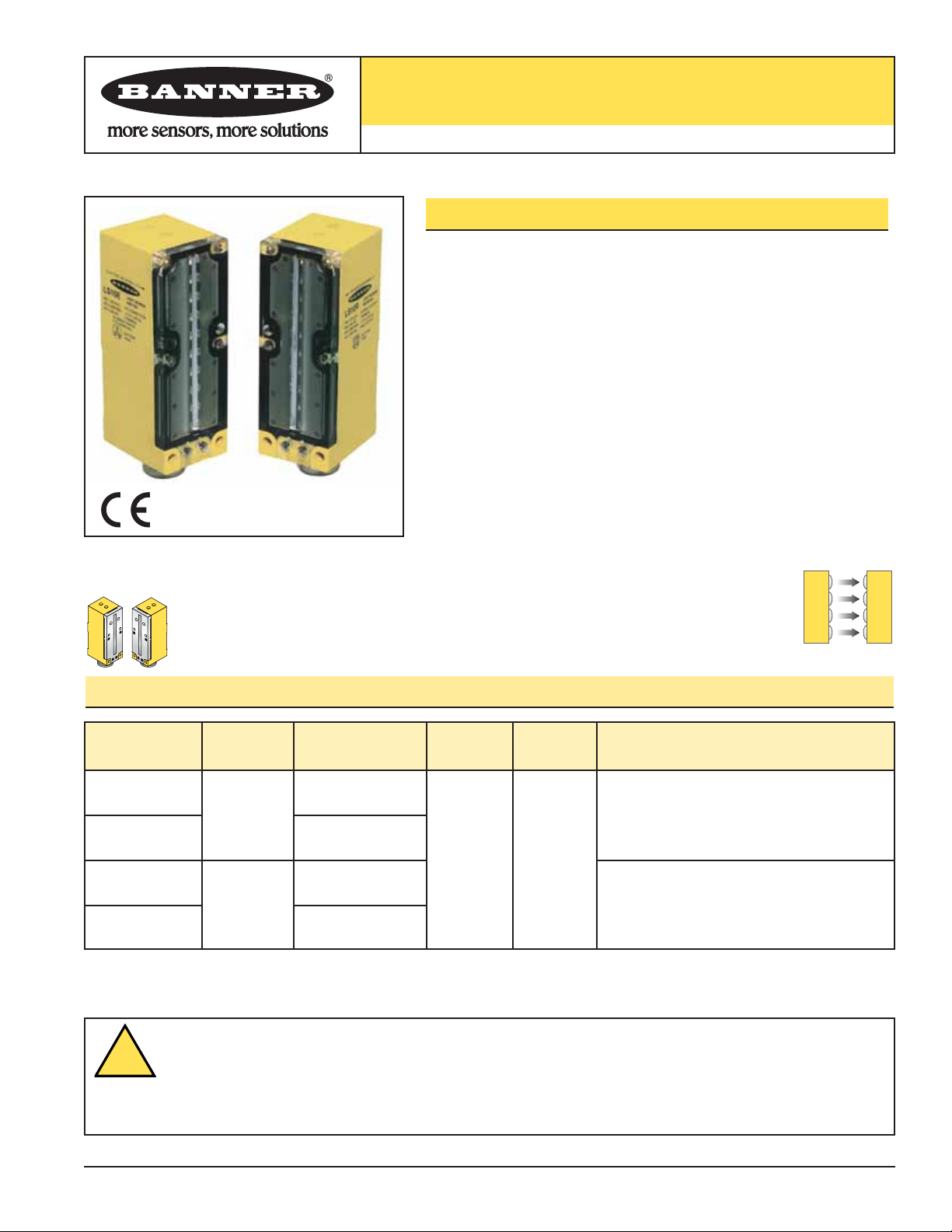
LS10 Light Screen System
• Emitter and receiver pair produce a strobed array of modulated light
beams to produce a light screen
• Simple, economical and highly reliable means of sensing small parts
which pass anywhere through the light screen
• Light screen area measures 90 mm (3.5") high, and as wide as the
distance between the emitter and receiver
• Fast, 1 millisecond response; output includes a 5-millisecond pulse
stretcher for interfacing reliability
• Tight beam spacing for sensing small parts as small as 5.6 mm (0.22")
diameter
• Totally self-contained; very rugged with totally encapsulated circuitry
• Bipolar design offers the choice of NPN (current sinking) or PNP
(current sourcing) outputs from the same receiver; both outputs may
be used simultaneously
LS10E
100 to 1220 mm
(4" to 48")
4-Pin Mini-style QD
7.6 mm (0.30")
LS10RSR
3-Pin Mini-style QD
Models Range Cable*
Supply
Voltage
Output
Type
Minimum Resolution
4-Pin Mini-style QD
LS10ESR
100 to 200 mm
(4" to 8")
3-Pin Mini-style QD
12-30V DC
Bipolar
NPN/PNP
DO
5.6 mm (0.22")
LS10R
Infrared, 880 nm
LS10 Series Opposed Mode Emitter (E) and Receiver (R)
WARNING . . .
Not To Be Used for Personnel Protection
Never use these products as sensing devices for personnel protection. Doing so could lead to serious injury or death.
These sensors do NOT include the self-checking redundant circuitry necessary to allow their use in personnel safety
applications. A sensor failure or malfunction can cause either an energized or de-energized sensor output condition. Consult your current
Banner Safety Products catalog for safety products which meet OSHA, ANSI and IEC standards for personnel protection.
!
Page 2
MULTI-BEAM®LS10 Light Screen System
2
Banner Engineering Corp. • Minneapolis, U.S.A.
www.bannerengineering.com • Tel: 763.544.3164
LS10 System Overview
LS10 Light Screen Systems consist of two self-contained units: an emitter and a
receiver. Multiple infrared LEDs in the emitter are aligned in a row and strobed (turned
ON one at a time) in a specific sequence and at a high frequency. Receivers contain a
matching array of phototransistors. The length (height) of the array is 90 mm (3.5"),
and produces a curtain of light as wide as the distance between the emitter and
receiver. The receiver may be placed 4" to 48" opposed from the emitter
(LS10E/LS10R) or 4" to 8" away (LS10ESR/LS10RSR). The LS10E/LS10R system can
detect objects as small as 7.6 mm (0.30") in diameter; minimum detectable object
profile for the LS10ESR/LS10RSR system is 5.6 mm (0.22").
NOTE: Sensing should not take place within 1/2" of any LS10 system sensor face.
The light from the emitter is modulated to minimize sensitivity to ambient light. An
indicator LED on the emitter lights whenever power is applied. The receiver has an
Alignment LED which lights whenever the beam is broken.
The receiver output interfaces directly with dc loads or circuits up to 30V dc, and
offers both sinking (NPN) and sourcing (PNP) output transistors. The sinking (NPN)
output may be connected directly to any Banner MAXI-AMP or MICRO-AMP logic
module for additional system control. Outputs are energized continuously while the
beam is broken. A 5 millisecond pulse stretcher (OFF delay) is included to improve
interfacing reliability.
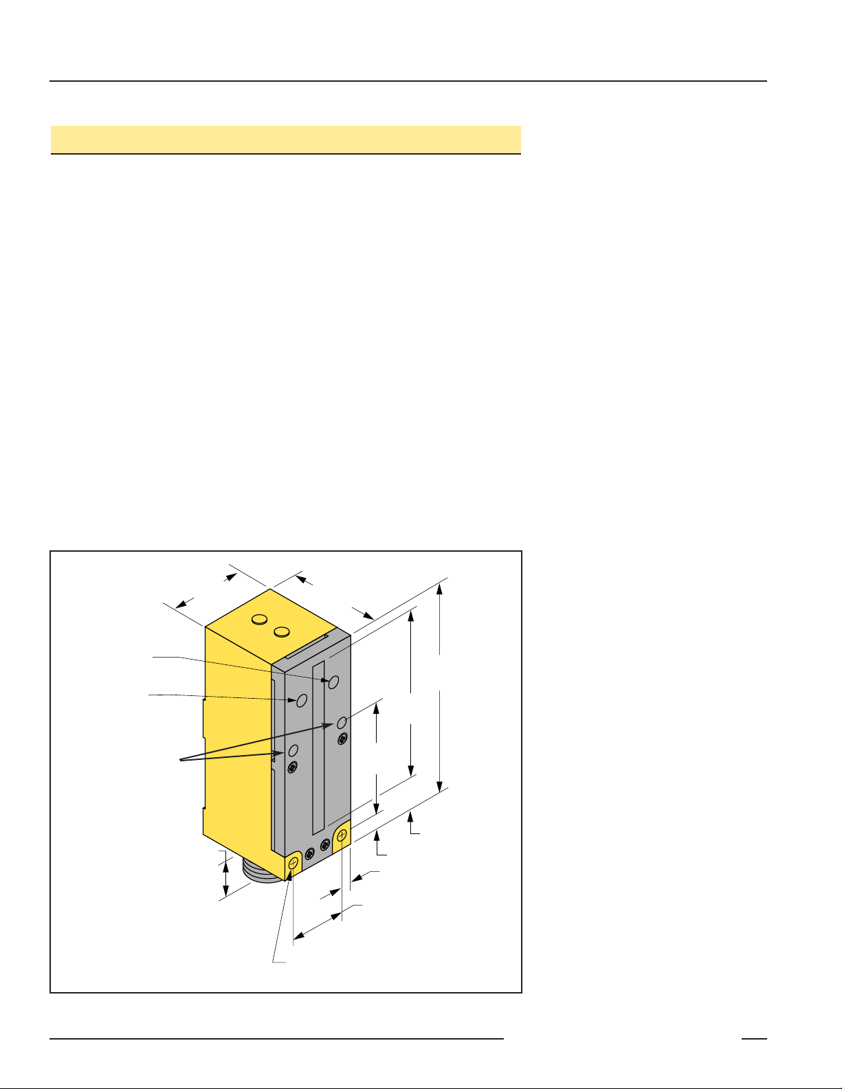
Figure 1. LS10 features
Max. Torque
2.28 Nm (20 in/lbs)
For Mounting Hardware
Receiver:
Alignment LED
Emitter:
Power ON LED
40.1 mm
(1.58")
13.2 mm
(0.52")
49.0 mm
(1.93")
116.0 mm
(4.55")
89.0 mm
(3.5")
60.0 mm
(2.36")
18.0 mm (0.71")
7.6 mm (0.30")
5.1 mm (0.20") (2)
30.0 mm (1.18") (2)
5 mm (0.2") (#10)
Screw Clearance (4)
Page 3

MULTI-BEAM®LS10 Light Screen System
3
Banner Engineering Corp. • Minneapolis, U.S.A.
www.bannerengineering.com • Tel: 763.544.3164
Installation and Alignment
The reliable performance of light screen systems requires careful alignment and
secure mounting. The 2-part, 3-axis mounting brackets on page 5 are highly
recommended. Mounting locations should be as free from vibration as possible. If
vibration is unavoidable, mount the emitter and receiver to vibrate together; no highamplitude differential vibration is allowed.
Mount the emitter and receiver at their operating locations with their front panels
exactly parallel and opposite each other. (The row of transmitter LEDs should be
exactly parallel with and opposite to the row of receiver phototransistors.) This
constitutes optimal mechanical alignment.
Optimal mechanical alignment does not always result in perfect optical alignment, and
perfect optical alignment is absolutely necessary. When optical alignment is
satisfactory, and emitter/receiver vibration is at moderate or lower levels, the receiver
Alignment status indicator (see Figure 1) will be OFF and remain OFF whenever the
light screen is unobstructed.
Adjusting Optical Alignment
Beginning with perfect mechanical alignment, adjust optical alignment as described in
steps #1 through #5. The procedure assumes use of the SMBLS mounting bracket
shown in Figure 2. Only the position of the emitter will be adjusted.
1) Loosen the two bolts holding the two parts of the bracket together just enough to
allow the upper (“carriage”) bracket, along with the emitter, to be rotated. Also,
slightly loosen the mounting bolts in the curved slots of the “base” bracket, which
will allow the bracket to be tipped from side to side.
2) With power applied to both the emitter and receiver, “tip” the entire bracket
(including the emitter) slightly from side to side. Find the extremes of movement
between which the receiver’s red Alignment LED remains OFF. Secure the base
bracket at the point midway between the extremes.
3) Rotate the carriage bracket (to which the emitter is attached) slightly in both
directions, as shown in Figure 2. Find the extremes of rotation between which the
receiver’s red Alignment indicator LED remains OFF. Secure the emitter midway
between the extremes by tightening the two bolts that lock the two parts of the
bracket together.
4) Loosen the two mounting bolts that hold the emitter to the carriage bracket. Slide
the emitter up and down vertically in the bracket, noting the extremes between
which the receiver’s Alignment LED indicator remains OFF. Tighten the bolts to
secure the emitter midway between the extremes. (NOTE: If the initial mechanical
alignment was inadequate, it may be necessary to repeatedly alternate tipping,
rotating, and sliding movements to attain perfect optical alignment.)
5) Check for proper alignment by moving a pencil (or a similar object) along the 3.5"
dimension of the sensing window. The receiver Alignment indicator LED and
outputs should come ON while the pencil is anywhere within the sensing window.
When this is true, tighten all mounting hardware securely in position.
Carriage
Figure 2. Achieving perfect optical
alignment with the LS10; bracket
SMBLS shown.
Bracket
Rotation
Sliding
Tipping
Base
Bracket
Page 4

MULTI-BEAM®LS10 Light Screen System
4
Banner Engineering Corp. • Minneapolis, U.S.A.
www.bannerengineering.com • Tel: 763.544.3164
LS10 Series Specifications
Certifications
Supply Voltage and Current 12 to 30V dc (10% maximum ripple) at less than 70 mA (emitter) or 45 mA (receiver – exclusive of load)
Supply Protection Circuitry Protected against reverse polarity
Output Configuration Bipolar: One current sourcing (PNP) and one current sinking (NPN) open-collector transistor
Output Rating 125 mA maximum each output
Off-state leakage current: less than 1 microamp
Output saturation voltage (PNP output): < 1 volt at 10 mA and < 2 volts at 150 mA
Output saturation voltage (NPN output): < 200 millivolts at 10 mA and < 1 volt at 150 mA
Output Protection Circuitry Protected against false pulse on power-up and continuous overload or short circuit of outputs
Output Response Time Receiver will respond to a “dark” signal of 1 millisecond or longer duration; a 5-millisecond pulse stretcher
(OFF Delay) is included to improve interfacing reliability; successive parts must have at least 10 millisecond
separation
Repeatability 30 microseconds (light-to-dark)
Resolution 5.6 mm (0.22") or 7.6 mm (0.30"), depending on model
Indicators Power (emitter only): lights whenever power is applied
Alignment (receiver only): lights whenever light screen is interrupted
Construction Reinforced thermoplastic polyester housing, acrylic lenses, and stainless steel hardware
Environmental Rating Meets NEMA standards 1, 2, 3, 12, and 13; IEC IP54
Connections See product selection tables
Operating Conditions Temperature: 0° to +50°C (+32° to 122°F)
Maximum relative humidity: 90% at 50°C (non-condensing)
Application Notes i) The best sensing resolution occurs near the center of the sensing area, midway between the emitter
and receiver.
ii) Outputs are energized continuously while the light screen is interrupted.
LS10 Emitters with Quick-Disconnect
(3-Pin Mini-Style)
LS10 Receivers with Quick-Disconnect
(4-Pin Mini-Style)
bn
bk
bu
+
–
12-30V dc
bn
wh
bu
+
–
bk
12-30V dc
Load
Load
LS10 Series Hookups
Black Wire
Blue Wire
Brown Wire
White Wire
Brown Wire
Black Wire
Blue Wire
Page 5

MULTI-BEAM®LS10 Light Screen System
5
Banner Engineering Corp. • Minneapolis, U.S.A.
www.bannerengineering.com • Tel: 763.544.3164
Accessories
Replacement Lens Assemblies
LS Series lens assemblies are field-replaceable.
Model Description
UC-LS10
UC-LS10SR
Replacement lens for LS10E and LS10R
Replacement lens for LS10ESR and LS10RSR
Quick-Disconnect (QD) Cables
4-Pin Mini
MBCC-406
MBCC-412
MBCC-430
2 m (6.5')
4 m (12')
9 m (30')
Style Model Length Connector
3-Pin Mini
MBCC-306
MBCC-312
MBCC-330
2 m (6.5')
4 m (12')
9 m (30')
Straight
Straight
Used with:
LS10 Series Emitters
LS10 Series Receivers
Mounting Brackets
SMBLS
• Two 11-gauge zinc plated steel, right angle brackets
fasten together to they can rotate relative to each other
• Assembly hardware and cable gland are included
SMB30UR
• 2-piece universal swivel bracket for limit-switch
style sensors
• 300 series stainless steel
• Includes stainless steel swivel locking hardware
64.0 mm
(2.52")
30.0 mm
(1.18")
4 x 6.0 mm
(0.24")
60.0 mm
(2.36")
4 x 16.0 mm
(0.64")
8X #10-32 Tap
172.0 mm
(6.77")
99.8 mm
(3.93")
57.2 mm
(2.25")
9.7 mm
(0.38")
50.8 mm
(2.00")
69.9 mm
(2.75")
57.2 mm
(2.25")
#10 Hardware
(included)
7.1 mm
(0.28") x 90°
(2 slots)
1/4"-28 x 1/2"
Screw
2X
66.0 mm
(2.60")
50.8 mm
(2.00")
70.0 mm
(2.76")
5 x 7 mm (1/4")
Clearance
Page 6

Banner Engineering Corp., 9714 Tenth Ave. No., Minneapolis, MN 55441 • Phone: 763.544.3164 • www.bannerengineering.com
MULTI-BEAM®LS10 Light Screen System
WARRANTY: Banner Engineering Corp. warrants its products to be free from defects for one year. Banner Engineering Corp. will repair or
replace, free of charge, any product of its manufacture found to be defective at the time it is returned to the factory during the warranty
period. This warranty does not cover damage or liability for the improper application of Banner products. This warranty is in lieu of any
other warranty either expressed or implied.
 Loading...