

Page 1
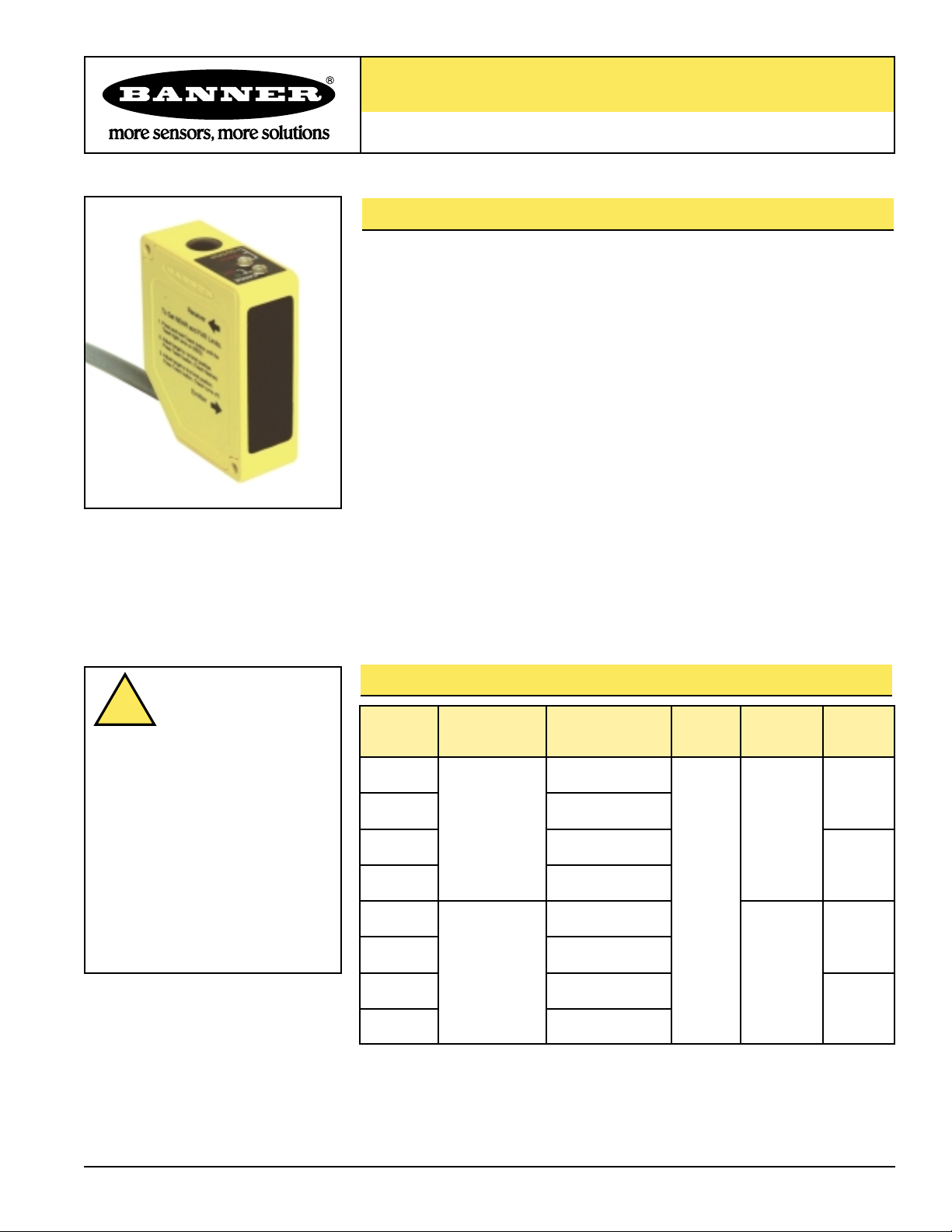
L-GAGE™Q50A Series with Analog Output
LED-Based Linear Displacement Sensor with Analog Output and TEACH-Mode
Programming
Printed in USA 06/01 P/N 67416
L-GAGE Q50A Analog Output Sensor Features
• Fast, easy-to-use TEACH-Mode programming; no potentiometer adjustments
• Selectable output response speeds: 4 milliseconds or 64 milliseconds (see hookup)
• Teach a sensing window size and position, or a 50 mm window centered on a
taught point
• Two sensing ranges, depending on model: 50 to 150 mm (visible red beam
models), and 50 to 200 mm (infrared beam models)
• Sensor linearity is better than 1.5 mm
• Banner’s patented scalable analog output (U.S. patent #6,122,039) automatically
distributes the output signal over the width of the programmed sensing window
• Analog output slope can be either positive or negative, depending upon which
window limit is programmed first
• Two bicolor Status LEDs
• Choose 2 meter or 9 meter unterminated cable, or swivel 5-pin Euro-style QD
connector
• Rugged construction withstands demanding sensing environments; rated IEC IP67,
NEMA 6
• Select models with either visible red or infrared beam
• Select models with either a 0-10V or 4-20 mA output
L-GAGE Q50A Analog Output Sensor Models
Model
Number
Sensing
Range Cable*
Supply
Voltage Beam Output
Q50AVI
50 to 150 mm
(2.0" to 5.9")
5-wire,
2 m (6.5') cable
15 to
30V dc
Visible Red
LED
4 to 20 mA
Q50AVIQ 5-pin Euro-style QD
Q50AVU
5-wire,
2 m (6.5') cable
0 to 10V
Q50AVUQ 5-pin Euro-style QD
Q50AI
50 to 200 mm
(2.0" to 7.9")
5-wire,
2 m (6.5') cable
Infrared LED
4 to 20 mA
Q50AIQ 5-pin Euro-style QD
Q50AU
5-wire,
2 m (6.5') cable
0 to 10V
Q50AUQ 5-pin Euro-style QD
* 9 meter cables are available by adding suffix “W/30” to the model number of any cabled
sensor (e.g., Q50AVI W/30). A model with a QD connector requires a mating cable;
see page 8.
WARNING . . .
Not To Be Used for
Personnel Protection
Never use these products as
sensing devices for personnel protection.
Doing so could lead to serious injury or
death.
These sensors do NOT include the selfchecking redundant circuitry necessary to
allow their use in personnel safety
applications. A sensor failure or
malfunction can cause either an energized
or de-energized sensor output condition.
Consult your current Banner Safety
Products catalog for safety products which
meet OSHA, ANSI and IEC standards for
personnel protection.
NOTE: Q50B models also available, with 100 to
400 mm range
!
Page 2
L-GAGE Q50A – Analog Output Sensor
page 2
Banner Engineering Corp. • Minneapolis, U.S.A.
www.bannerengineering.com • Tel: 763.544.3164
L-GAGE Q50A Analog Output Sensor Overview
The Q50A is an easy-to-use triangulation sensor which provides
a sophisticated, yet cost-effective solution for demanding
measurement applications. Q50A Series sensors feature
compact, all-in-one design and require no separate controller.
Near and far sensing window limits are set quickly using simple
push-button or remote signal TEACH-mode programming. The
analog output has the option of being set with a sensing
distance centered within a 50 mm window. The sensor features
Banner’s patented digital signal processing algorithm (U.S. patent
#6,122,039), which automatically distributes the 0 to 10V dc (or 4
to 20 mA) output signal over the width of the programmed
window.
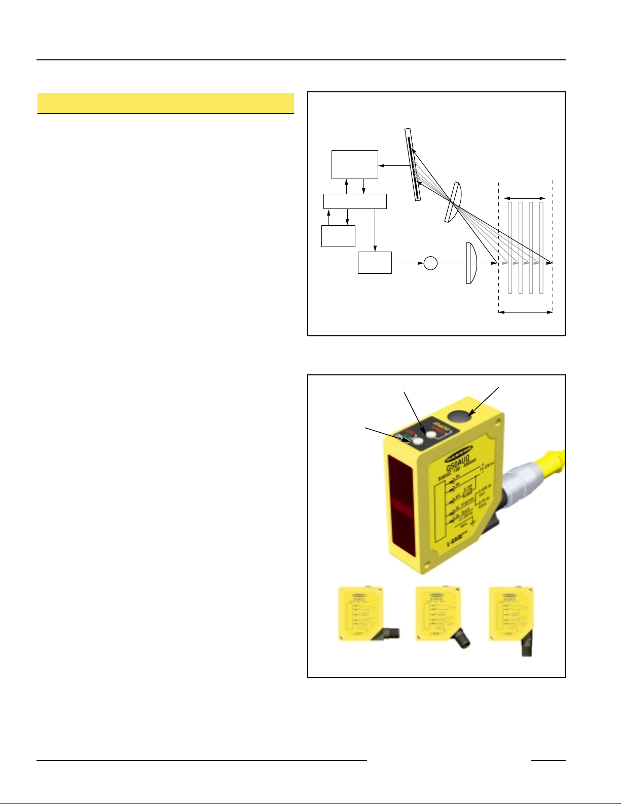
Optical Triangulation
The function of the Q50A Sensor is based on optical
triangulation (see Figure 1). The emitter circuitry and optics
create a light source which is directed toward a target. The light
source bounces off the target, scattering some of its light
through the sensor’s receiver lens to its position-sensitive-device
(PSD) receiver element. The target’s distance from the receiver
determines the light’s angle to the receiver element; this angle
determines where the returned light will touch the PSD receiver
element.
The position of the light on the PSD receiver element is
processed through analog and digital electronics and analyzed
by the microprocessor, which calculates the appropriate output
value. The analog output provides either a current or voltage
output proportional to the target’s position within the userprogrammed analog window limits (see page 4).
Figure 1. Using optical triangulation to determine sensing distance
Figure 2. L-GAGE Q50A sensor features
Range
Indicator LED
(red or green)
Teach/Output
Indicator LED
(yellow or red)
Programming
Push Button
QD fitting rotates for hookup in any direction
PSD
Receiver
Element
R
Signal
Conditioning
Circuitry
Microprocessor
Output
Circuitry
Emitter
Circuitry
E
Emitter
Lenses
Near
Limit
Target Movement
Programmed
Sensing Window
Far
Limit
Page 3
L-GAGE Q50A – Analog Output Sensor
page 3
Banner Engineering Corp. • Minneapolis, U.S.A.
www.bannerengineering.com • Tel: 763.544.3164
Using the L-GAGE Q50A Analog Output Sensor
Response Speed
To control the response speed, connect the black wire as
follows:
Fast Speed (4 ms): Connect black wire to +5 to 30V dc
Slow Speed (64 ms): Connect black wire to 0 to +2V dc (or
open connection)
Window Limits
Window limits may be taught to the sensor either remotely
(using the gray wire) or by using the sensor’s Teach push
button.
The Q50A sensor operates in two modes: TEACH (or
programming) mode and RUN mode.
NOTE: All LED indicators momentarily go OFF when the sensor
changes state between RUN and TEACH modes.
Indicator Status Conditions
Indicator Status
Range LED Green — Target is within sensing range
(green/red) Red — Target is outside sensing range
OFF — Sensor Power OFF
Teach/Output Yellow — Target is within taught window limits
LED OFF — Target is outside taught window limits
(yellow/red) Red — Sensor is in TEACH mode
TEACH-Mode Programming
Push-Button Procedure
1. Press the Teach push button until the Teach LED turns red
(hold button in for about 2 seconds). This indicates the
sensor is waiting for the first window limit.
2. Position the target for the first limit. The Range LED should be
green, indicating a valid target. Briefly “click” the Teach push
button. This will teach the sensor the first limit. The Teach
LED will flash red at 2 Hz to acknowledge receiving the first
window limit; it is now waiting for the second limit.
3. Position the target for the second limit and “click” the Teach
push button again to teach the sensor the second limit. The
Teach LED will return to either yellow or OFF as the sensor
returns to RUN mode.
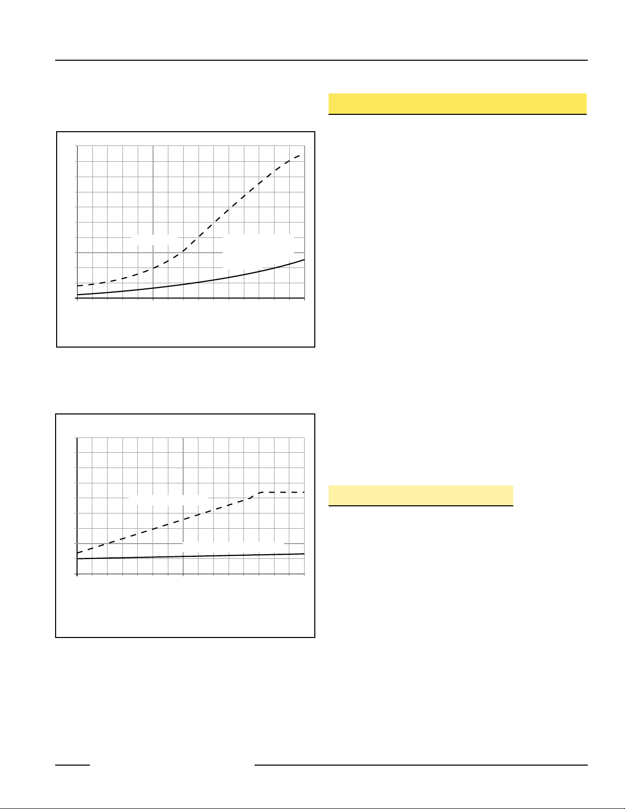
Figure 4. L-GAGE Q50A color sensitivity (This represents the
expected change in output when the target color is
changed from a 90% reflectance Kodak White Card to a
6% and 18% reflectance surface.)
Figure 3. L-GAGE Q50A resolution
Q50A (infrared models) range is 50 - 200 mm
Q50AV (visible models) range is 50 - 150 mm
5
4
3
2
Resolution (mm)
1
0
50
NOTE: Resolution is independent of color (90% Kodak White Card to 6% Black)
Fast Response
100
Distance (mm)
Slow Response (90%
Reflectance Kodak White
Card to 6% Reflectance
Black Card)
150 200
9
8
7
6
5
4
3
Color Sensitivity (mm)
2
1
0
50
NOTES:
Color sensitivity is independent of response time
Q50A (infrared models) span is 50-200 mm
Q50AV (visible models) span is 50-150 mm
6% Reflectance Black Card
18% Reflectance Kodak Grey Card
100
Distance (mm)
150 200
Page 4

L-GAGE Q50A – Analog Output Sensor
page 4
Teaching Analog Limits Using a Fixed 50 mm Window
For some analog applications, a fixed sensing window centered about a taught point is
required. The TEACH procedure is simple: teaching the same limit twice causes the
sensor to program a window centered on the position taught. This window is 50 mm
wide (taught position ± 25 mm).
Remote Programming
A function is provided to program the sensor remotely or to disable/enable the push
button; this is accomplished via the gray wire. Disabling the push button prevents
anyone on the production floor from adjusting any of the programming settings.
Connect the gray wire of the Q50A Gauging Sensor to +5 to 30V dc, with a remote
programming switch connected between them. NOTE: The impedance of the remote
teach input is 15 kΩ.
To program, pulse the wire as illustrated in Figure 5. NOTE: The duration of each pulse
(corresponding to a push button “click”) is 0.04 to 0.8 seconds.
Figure 5. Timing for remote TEACH programming
Run Mode
NOTE: All LED indicators momentarily go OFF when the sensor changes state between
RUN and TEACH modes.
Range LED
When the sensor detects a target within its sensing range (either 50 to 150 mm for
visible-beam models, or 50 to 200 mm for infrared beam models) the LED will be solid
green. In the absence of a target, the Range LED is solid red. Refer to the Indicator
Status table on page 3.
Teach/Output LED
In RUN mode, the Output LED is yellow when a target is sensed within the
programmed window limits; otherwise the Output LED is red. Refer to the Indicator
Status table on page 3.
Analog Output
The Q50A gauging sensor may be programmed for either a positive or a negative output
slope (see Figure 6). If the near limit is taught first, the slope will be positive; if the far limit
is taught first, the slope will be negative. Banner’s patented scalable analog output
automatically distributes the output signal over the width of the programmed sensing
window. (Output is either 0 to 10V or 4 to 20 mA, depending on model.)
Figure 6. Analog voltage output as a
function of target position
(loss of signal – 0 Volts)
Figure 7. Analog current output as a
function of target position
(loss of signal – 3.6 mA)
Banner Engineering Corp. • Minneapolis, U.S.A.
www.bannerengineering.com • Tel: 763.544.3164
> 0.8 sec
T
Teach Second
Window Limit
Push Button Lockout
Remote Teach
Window Limits
Push Button
Lockout
T
Teach First
Window Limit
TTTTTTT
0.04 sec < T < 0.8 sec
10
Analog Output (V dc)
0
Near
Window
Positive
Slope
Target Position
Far
Window
20
Positive
Slope
Analog Output (mA)
4
Near
Window
Target Position
Far
Window
Page 5

L-GAGE Q50A – Analog Output Sensor
page 5
Banner Engineering Corp. • Minneapolis, U.S.A.
www.bannerengineering.com • Tel: 763.544.3164
Installation Notes
Some targets (those with a stepped plane facing the sensor, a boundary line, or
rounded targets) pose specific problems for sensing distances. For such applications,
see Figure 8 for suggested mounting orientations.
Figure 8. Sensor orientations for typical targets
Recommended
NOT Recommended
Page 6

L-GAGE Q50A Analog Output Sensor Specifications
L-GAGE Q50A – Analog Output Sensor
page 6
Banner Engineering Corp. • Minneapolis, U.S.A.
www.bannerengineering.com • Tel: 763.544.3164
Q50A: 50 to 200 mm (2" to 7.9")Sensing Range
Linearity
Output Protection
Supply Voltage 15 to 30V dc (10% maximum ripple); 70 mA max. (exclusive of load)
Supply Protection Circuitry Protected against reverse polarity and transient over voltages
Delay at Power-up 2 seconds
Sensing Beam Wave length Q50AV: 685 nm (typical) Q50A: 880 nm (typical)
Beam Size Q50AV: 20 mm dia. (max.) Q50A: 20 mm dia. (max.)
Output Configuration Depending on model
4-20 mA current sourcing models: 1 kΩ max. load @ 24V dc. Max. load = [(Vcc-4.5)/0.02]Ω
Loss of signal or target outside of sensor range: 3.6 mA
0-10V voltage sourcing models: 15 mA max.
Loss of signal or target outside of sensor range: 0V
Protected against short circuit conditions
Temperature Drift
Output Response Time Analog Output Average Update -3 dB Frequency
Interval Rate Response
Fast: 4 ms 1 ms 112 Hz
Slow: 64 ms 4 ms 7 Hz
±1.5 mm
Resolution See Figure 3 for typical values
Target Distance:100 mm
Slow Response: 0.5 mm max.
Fast Response: 2.0 mm max.
Color Sensitivity (typical) See Figure 4
Q50AV: 50 to 150 mm (2" to 5.9")
From 0° to 50°C: 0.08 mm/°C
From -10° to 55°C: 0.11 mm/°C
Remote and Speed Input
Impedance
15 kΩ
Remote Teach Input To Teach: Connect gray wire to +5 to 30V dc
To Disable: Connect gray wire to 0 to +2V dc (or open connection)
Adjustments Response Speed:
Fast Speed: Connect black wire to +5 to 30V dc
Slow Speed: Connect black wire to 0 to +2V dc (or open connection)
Indicators Range LED Green — Target is within sensing range
Indicator Red — Target is outside sensing range
(green/red) OFF — Sensor Power OFF
Teach/Output Yellow — Target is within taught window limits
LED Indicator OFF — Target is outside taught window limits
(yellow/red) Red — Sensor is in TEACH mode
Minimum Taught Window
Model #
Ambient Light Immunity <10,000 Lux
Distance
Q50A
Q50AV
5 mm
5 mm
10 mm
10 mm
15 mm
15 mm
20 mm
20 mm
25 mm
25 mm
–
35 mm
–
50 mm
50 mm 75 mm
100 mm 125 mm 150 mm 175 mm 200 mm
Page 7

L-GAGE Q50A Analog Output Sensor Specifications (continued)
L-GAGE Q50A Dimensions
L-GAGE Q50A – Analog Output Sensor
page 7
Banner Engineering Corp. • Minneapolis, U.S.A.
www.bannerengineering.com • Tel: 763.544.3164
Bare
GE
Connections 2 m or 9 m 5-conductor PVC-covered attached cable or 5-pin Euro-style quick disconnect
Construction Housing: Molded ABS/Polycarbonate
Window Lens: Acrylic
Environmental Rating IEC IP67, NEMA 6
Vibration and
Mechanical Shock
All models meet Mil. Std. 202F requirements. Method 201A (Vibration: 10 to 60Hz max. double amplitude
0.06", maximum acceleration 10G). Also meets IEC 947-5-2 requirements: 30G, 11 ms duration, half sine
wave.
Operating Conditions Temperature: -10° to +55°C (+14° to +131°F)
Max. Rel. Humidity: 90% at +50°C (non-condensing)
Application Notes Allow 15-minute warm-up for maximum linearity.
Hardware M3 hardware is included.
L-GAGE Q50A Hookups
Cable Models
Quick-Disconnect Models
77.0 mm
(3.03")
60.0 mm
(2.36")
M3 Hardware is Included
Receiver
To Set NEAR and FAR Limits.
1. Press and hold Teach button until the
Teach light turns on (RED)
2. Adjust target to 1st limit position.
Press Teach button. (Teach flashes)
3. Adjust target to 2nd limit position.
Press Teach button (Teach turns off)
Emitter
bn
bu
wh
bk
gy
Load
Response
each
T
+5-30V dc
Bare
25 mm
(0.98")
15 mm
(0.59")
+
15-30V dc
–
5-30V dc
4ms
0-2V dc
s
64m
IN
19.7 mm
(0.77")
15 mm
(0.59")
52.0 mm
(2.05")
OUT
RANGE
RANGE: 100 - 400mm
TEACH
OUTPUT
49.8 mm
(1.96")
Q50AUQ
bn
bubnbu
wh
bk
gy
+5-30V dc
L-GA
4.0 mm
(0.16")
4.0 mm
(0.16")
41.8 mm
(1.65")
67.3 mm
(2.65")
15-30V dc
Load
5-30V dc
response
4ms
Teach
0-2V dc
64ms
2x ø3.4 mm
(0.13")
Q50AU
RANGE: 100 - 400mm
+
–
bnbubn
bu
wh
Load
Response
bk
gy
each
T
+5-30V dc
bn
bubnbu
wh
response
bk
gy
Teach
+5-30V dc
Bare
L-GAGE™
+
15-30V dc
–
5-30V dc
4ms
0-2V dc
64ms
+
15-30V dc
–
Load
5-30V dc
4ms
0-2V dc
64ms
Bare
Page 8

Euro-Style Quick-Disconnect Cables
L-GAGE Q50A – Analog Output Sensor
Banner Engineering Corp., 9714 Tenth Ave. No., Minneapolis, MN 55441 • Phone: 763.544.3164 • www.bannerengineering.com • Email: sensors@bannerengineering.com
WARRANTY: Banner Engineering Corp.
warrants its products to be free from
defects for one year. Banner Engineering
Corp. will repair or replace, free of charge,
any product of its manufacture found to
be defective at the time it is returned to
the factory during the warranty period.
This warranty does not cover damage or
liability for the improper application of
Banner products. This warranty is in lieu
of any other warranty either expressed or
implied.
Accessories
Mounting Brackets
SMBQ50
• Right-angle bracket
• 14-ga., 304 Stainless Steel
5-Pin Euro
Straight
MQDEC2-506
MQDEC2-515
MQDEC2-530
2 m (6.5')
5 m (15')
9 m (30')
Style Model Length Connector
Pin-out
5-Pin Euro
Right-
angle
MQDEC2-506RA
MQDEC2-515RA
MQDEC2-530RA
2 m (6.5')
5 m (15')
9 m (30')
44 mm max.
(1.7")
38 mm max.
M12 x 1
ø 15 mm
(0.6")
(1.5")
42.0 mm
4.0 mm
(0.16")
3x ø3.9 mm
(0.16")
(1.65")
8.0 mm
(0.32")
45°
15.0 mm
(0.60")
53.0 mm
(2.09")
4.0 mm
(0.16")
67.0 mm
(2.63")
R 66.7 mm
(2.63")
3°
ø 15 mm
(0.6")
M12 x 1
38 mm max.
(1.5")
Brown Wire
Black Wire
White Wire
Blue Wire
Gray Wire
7.0 mm
(0.28")
6°
38.8°
1.9 mm
(0.07")
10.0 mm
(0.39")
4.2 mm
(0.17")
32.5 mm
(1.28")
20.0 mm
(0.79")
1.9 mm
(0.07")
10°
R24.1 mm
(0.95")
3x R2.25 mm
(0.09")
5°
 Loading...