

Page 1
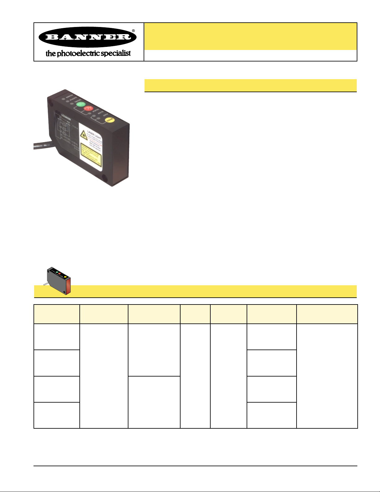
L-GAGE Laser Gauging Sensor Models
L-GAGE™Laser Gauging Sensor – 45 to 60 mm Range
Class 2 visible laser displacement sensor with both analog and discrete (switched) outputs
Printed in USA P/N 55801
L-GAGE Laser Gauging Sensor Features
• Self-contained Class 2 modulated visible laser gauging sensor needs no separate controller
• Narrow effective beam is excellent for precision distance, height or thickness
measurement or gauging applications
• Resolution to better than 10 microns
• Sensing window may be sized as needed, and placed anywhere within the
45.0 to 60.0 millimeter (1.77" to 2.36") sensing distance; 1.5 mm (0.06") minimum
window size
• Banner’s unique scalable analog output (patent pending) automatically distributes
the output signal over the width of the programmed sensing window
• Analog and discrete (switched) outputs
• Window limits for analog and discrete outputs may be set independently
• Analog output slope is either positive or negative, depending upon which window
limit is programmed first
• Fast, easy-to-use integrated push-button TEACH-mode programming; no
potentiometer adjustments
• Remote TEACH function for security and convenience
• Unique feature holds analog output value for 2 seconds upon loss of signal
• Modulated laser beam and narrow optical band-pass filter provide a high level of
ambient light immunity, including immunity from high-energy factory lighting
• Alarm output for signal saturation
• Output response is programmable for three speeds
• 12 to 30V dc operation
• Enclosure rated IECIP67; NEMA 4X
LG5B65PI
Models Sensing Distance Cable*
Supply
Voltage
LG5B65NI
45.0 to 60.0 mm
(1.77 to 2.36")
2 m (6.5')
8-wire
12 to 30V dc
* NOTE: 9 m (30') cables are available by adding suffix “W/30” to the model number of any cabled sensor (e.g., LG5A65NI W/30)
†
See Figure 2 on page 4 for more information. NOTE: In general, 70 mm focal point models are recommended for most distance measurement
applications, because small surface irregularities will be averaged out due to the larger beam size.
TEACH
SLOW
FAST
P
O
W
E
R
O
U
T
P
U
T
S
IG
N
A
L
SPEED
A
D
PNP (sourcing)
Discrete Output
NPN (sinking)
Analog Output
Analog current output
(4 to 20 mA)
PNP (sourcing)
LG5A65PI
NPN (sinking)
LG5A65NI
Focal Point
†
53 mm (2.1")
Beam size at 53 mm:
ø0.1 mm (ø0.004")
70 mm (2.8")
Beam size at 53 mm:
0.4 x 0.6 mm
(0.016 x 0.024")
Page 2
L-GAGE™ Laser Gauging Sensor
page
2
L-GAGE Laser Gauging Sensor Overview
Banner’s Class 2 visible laser displacement sensor brings a sophisticated, yet costeffective solution to precision measurement applications. L-GAGE Series sensors
feature all-in-one design and require no separate controller.
Near and far sensing window limits are set quickly using simple push-button or
remote signal TEACH-mode programming. One sensor can simultaneously provide
both analog and discrete (switched) outputs. Sensing window limits for each output
may be independently programmed, if desired. The analog signal features Banner’s
unique scalable output (patent pending), which automatically distributes the 4 to 20
milliamp output signal over the width of the programmed sensing window. If an
analog voltage output is required, this can be accomplished by using an alternate
hookup. (See Hookups, page 5.)
The L-GAGE Laser Gauging Sensor boasts many additional features, including
selectable response speed, self-diagnostics with alarm output, comprehensive status
indicator system, and unique output “hold” function for momentary signal loss in
profiling applications.
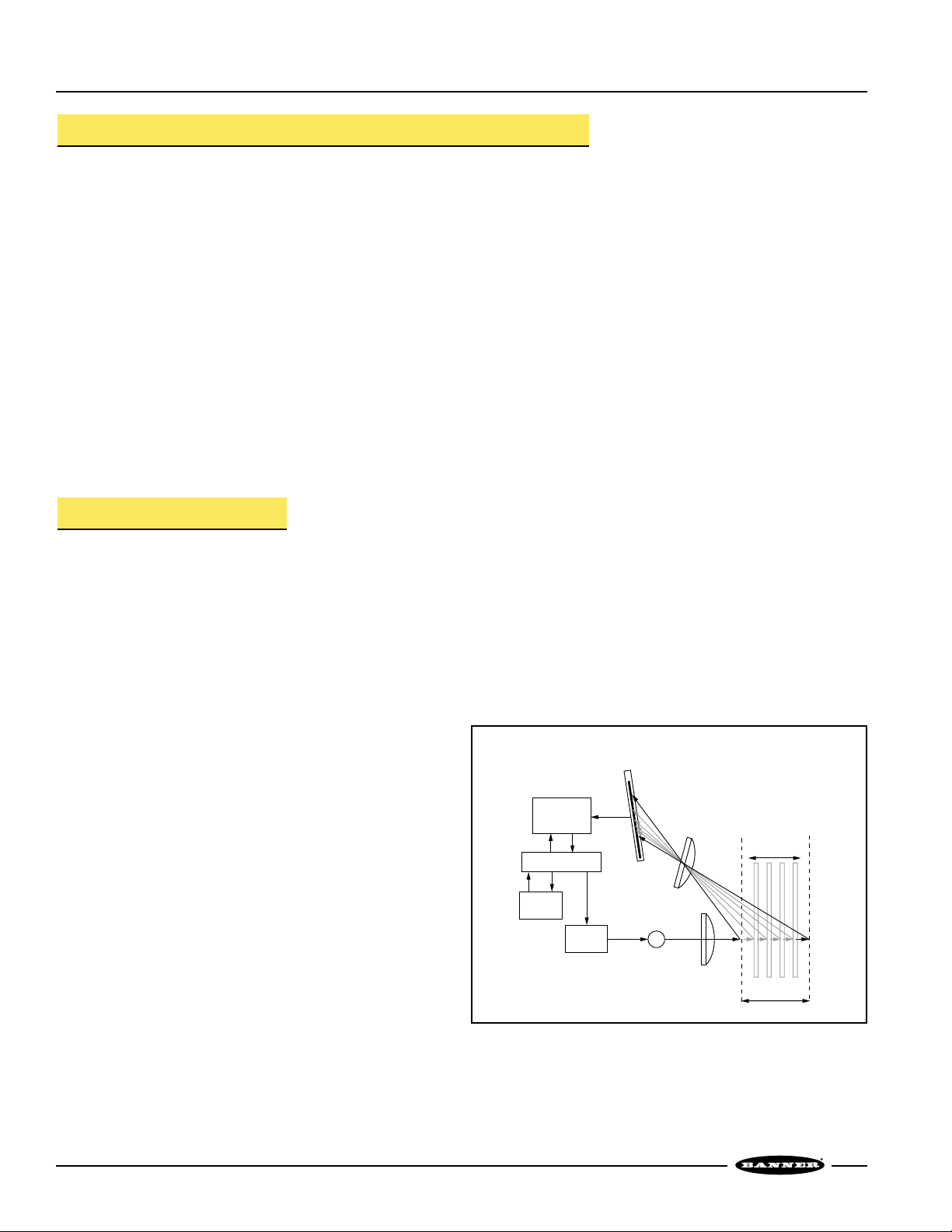
Optical Triangulation
The design of the L-GAGE Laser Gauging Sensor is based on optical triangulation (see
figure 1). An emitter transmits visible laser light through a lens, toward a target. The
laser light beam from the emitter bounces off the target, scattering some of its light
through another lens to the sensor’s PSD (position-sensitive device) receiver element.
The target’s distance from the receiver determines the angle the light travels to the
receiver element; this angle in turn determines where the received light will fall along
the PSD receiver element.
The position of the light on the PSD receiver element is processed through analog
and digital electronics and analyzed by the microprocessor,
which calculates the appropriate output value. The analog
output provides a variable 4 to 20 milliamp current that is
proportional to the target’s position within the user-programmed
analog window limits (see page 8). The discrete (switched)
output energizes whenever the target is located between the
user-programmed discrete window limits. Analog and discrete
window limits may be the same, or programmed independently.
Figure 1. Optical triangulation sensing system overview
Signal
Conditioning
Circuitry
Microprocessor
Output
Circuitry
Emitter
Circuitry
PSD
Receiver
Element
R
E
Laser
Emitter
Lenses
Near
Limit
Target Movement
Programmed
Sensing Window
Far
Limit
Page 3

L-GAGE™ Laser Gauging Sensor
page
3
L-GAGE Laser Gauging Sensor Specifications
Sensing Range
Supply Voltage 12 to 30V dc, (10% maximum ripple); 50 mA max at 24V dc (exclusive of load)
Supply Protection Circuitry Protected against reverse polarity, over voltage, and transient voltages
Delay at Power-up 1.25 second
Sensing Beam 670 nm visible red IEC and CDRH Class 2 laser; 0.15 mW radiant output power
Output Configurations Discrete (switched) output: SPST solid-state switch; choose NPN (current sinking) or PNP (current
sourcing) models
Analog output: 4 to 20 milliamp current sourcing
Alarm output: SPST solid-state switch; NPN (current sinking) or PNP (current sourcing), depending on
discrete output model
Output Ratings Discrete (switched) and Alarm output: 100 mA maximum
Off-state leakage current: less than 5 microamps
Output saturation voltage (PNP output): less than 1.2 volts at 10 mA and less then 1.6 volts at 100 mA
Output saturation voltage (NPN output): less than 200 millivolts at 10 mA
and less then 600 millivolts at 100 mA
Analog output: 1 kΩ max @ 24V dc; max load resistance = Vcc – 3.3
[
0.02
Ω
]
Output Response Time Discrete Output:
Fast: 3.6 milliseconds ON and OFF
Medium: 10 milliseconds ON and OFF
Slow: 40 milliseconds ON and OFF
Analog Output (-3 dB):
Fast: 250 Hz (1.6 milliseconds average with 1.6 millisecond update rate)
Medium: 40 Hz (10 milliseconds average with 1.6 millisecond update rate)
Slow: 10 Hz (40 milliseconds average with 2.1 millisecond update rate)
Analog Resolution and
Repeatability of Discrete
Trip Point*
Fast: 0.06% of sensing distance (<30 microns @50 mm)
Medium: 0.03% of sensing distance (<15 microns @50 mm)
Slow: 0.02% of sensing distance (<10 microns @50 mm)
Analog Linearity* ± 60 microns (±0.002")
Hyste r esis (Discrete Output) <0.35% of sensing distance
Laser Control Connect green wire to +5 to 30V dc to enable laser beam; connect to 0 to +1.8V dc (or open connection)
to disable; 250 millisecond delay upon enable.
45.0 to 60.0 mm (1.77" to 2.36")
Adjustments Response speed: push button toggles between 1.6, 10, and 40 milliseconds
Window limits (analog or discrete): TEACH-mode programming of near and far window limits (see
programming procedure). Limits may also be taught remotely via TEACH input (see page 7).
Analog output slope: the first limit taught is assigned to minimum output current (4mA).
Output Protection Outputs are protected against continuous overload and short circuit
Color Sensitivity* <75 microns (0.003") (typical) for white to dark gray ceramic target
Temperature Drift ±7 microns/°C
*Using white ceramic test surface (see Application Notes).
Resolution and linearity specified at 24V dc, 22°C.
Minimum Window Size
(Analog or Discrete)
1.5 mm (0.06")
Remote Teach and Laser
Control Input Impedance
55 kΩ
Page 4
G
N
L-GAGE Laser Gauging Sensor Specifications (continued)
L-GAGE™ Laser Gauging Sensor
page
4
Indicators
Construction Housing: Zinc alloy die-cast, plated and painted finish
Cover plate: aluminum with painted finish
Lens: acrylic
Green Power ON LED: Indicates when power is ON, overloaded output and laser status.
Yellow Output LED: Indicates when discrete load output is conducting.
Red Signal LED: Indicates when target is within sensing range and the condition of the received light
signal.
Tri-color Red/Green/Yellow TEACH LED: Indicates sensor is ready for programming each limit (indicates
red for analog output, green for discrete, and yellow for simultaneous analog and discrete.)
Yellow Fast/Slow LEDs: Combination of 2 lights ON or OFF indicates one of 3 response speeds.
NOTE: See page 5 for more information on indicator behavior.
Environmental Rating IP67, NEMA 4X
Vibration and
Mechanical Shock
Vibration: 60 Hz, 30 minutes, 3 axes
Shock: 30G for 11 milliseconds, half sine wave, 3 axes
Operating Conditions Temperature: -10° to +50° C (+14° to 122° F)
Maximum relative humidity: 90% at 50° C, non-condensing
Application Notes For comparison, white ceramic test surface has approximately 91% of the reflectivity of a white Kodak test
card with a matte finish. A dark gray ceramic test surface has approximately 11% of the reflectivity of a white
Kodak test card with a matte finish.
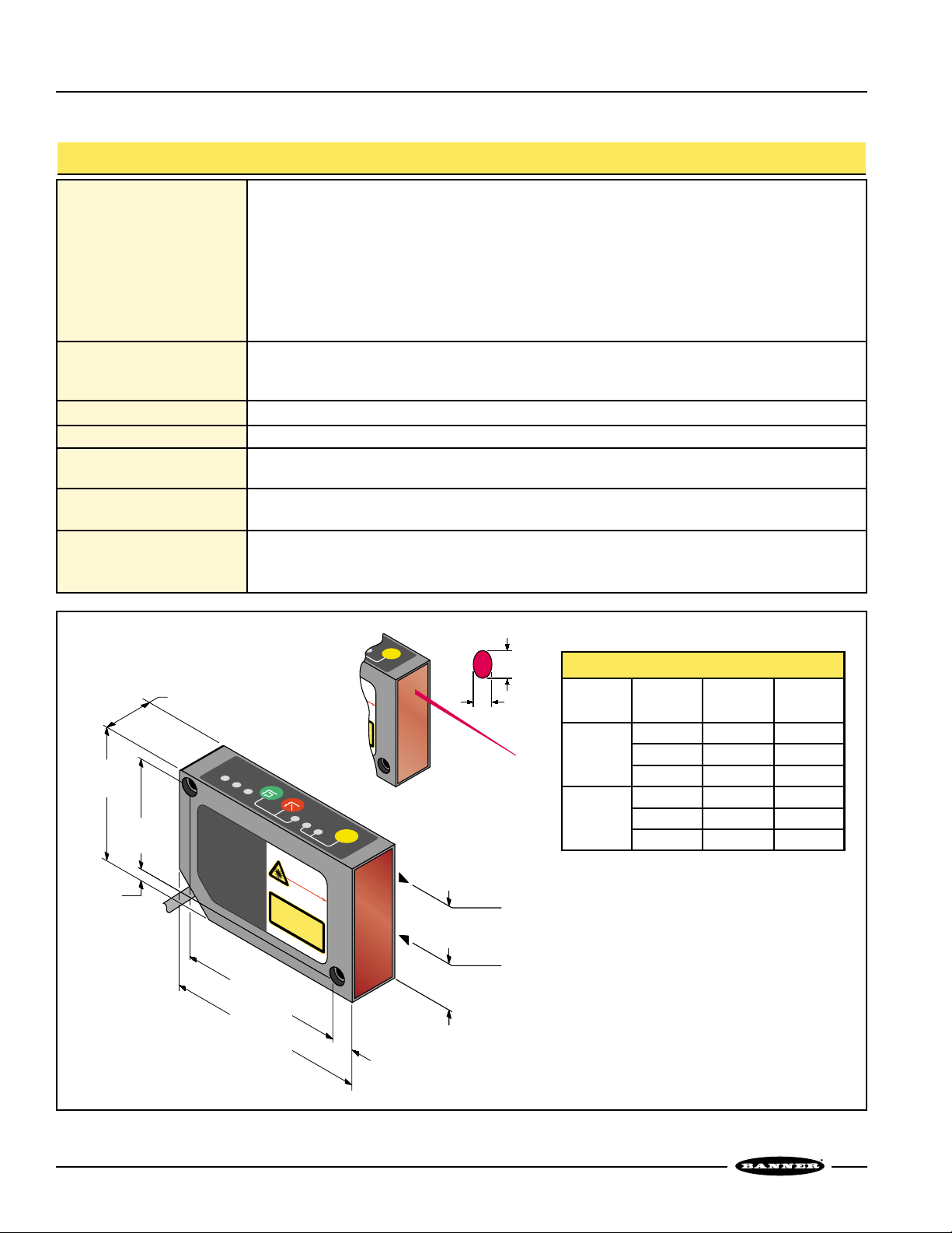
Figure 2. L-GAGE Laser Gauging Sensor and beam dimensions
Connections 2 m (6.5') or 9 m (30') 7-conductor shielded PVC-jacketed attached cable.
L-GAGE Beam Dimensions (typical)
Focal
Point
†
Distance
Beam
Width (X)
Beam
Height (Y)
53 mm
(2.1")
45 mm 0.3 mm 0.5 mm
60 mm
53 mm
0.3 mm
0.1 mm
0.5 mm
0.1 mm
70 mm
(2.8")
45 mm 0.6 mm 0.9 mm
53 mm 0.4 mm 0.6 mm
60 mm 0.3 mm 0.4 mm
† The Focal Point is the distance measured from
the lens (front of sensor) at which the diameter
of the laser image is smallest.
A
L
D
A
55.3 mm
(2.18")
4.6 mm
(0.18")
45.5 mm
(1.79")
20.2 mm (0.80")
POWER
68.3 mm
OUTPUT
SIGNAL
(2.69")
D
R
A
D
IA
8
K
N
H
z
6
8
6
-1
0
- 6
C
8
O
M
P
1
0
L
4
IE
0
.1
0
A
LASER LIGHT
D
O
N
O
C
T
L
A
S
S
T
S
A
R
2
E
L
A
I
N
S
E
R
Avoid exposure -
P
laser light emitted
from his aperture
T
P
O
W
6
E
%
R
D
0
0
U
n
.1
T
m
5
Y
m
C
S
Y
W
C
A
L
IT
N
H
D
2
E
1
C
N
6
F
0
R
8
2
5
-1
TEACH
T
O
R
O
W
E
:1
9
B
E
A
M
D
U
C
T
9
4
LASER LIGHT
D
O
N
C
O
L
T
A
S
S
A
v
l
a
s
f
r
o
RADIANT POWER 0.15 mW
8KHz 8-16% DUTY CYCLE
660 - 680 nm
COMPLIES WITH 21 CFR
1040.10 AND EN60825-1:1994
SLOW
FAST
S
T
A
2
L
A
S
o
i
d
e
e
r
l
i
m
h
SPEED
TEACH
SLOW
FAST
R
E
I
N
T
E
O
R
B
P
E
R
A
O
M
D
U
C
x
p
T
o
s
g
u
h
r
e
t
e
-
m
i
s
i
t
a
t
e
p
d
e
r
t
u
r
e
SPEED
23.9 mm
19.1 mm
Beam Dimensions
X
Emitted Light
(0.94")
Received Light
(0.75")
Y
82.3 mm
(3.24")
9.3 mm
(0.37")
Page 5

L-GAGE™ Laser Gauging Sensor
page
5
L-GAGE Laser Gauging Sensor Hookups
NPN Hookup
PNP Hookup
Conversion from Current to
Voltage Output
*NOTE: The bare shield wire should be connected as follows:
1) If the sensor housing is mounted so that it is in continuity with both the machine
frame and earth ground, connect the bare wire (also) to earth ground.
2) If the sensor housing is mounted so that it is insulated from the machine frame,
connect the bare wire to -V dc (together with the blue wire).
3) If the sensor is mounted so that it is in continuity with the machine frame, but
not with earth ground, do not connect the bare wire (i.e. cut off the bare wire).
**NOTE:
For best results, install a small
amount of capacitance (e.g., 0.1µF)
in parallel with the load resistor
Typical Voltage Response
Value
of R
Output Voltage
250Ω
500Ω
1 to 5V
2 to 10V
Modes
The L-GAGE Laser Gauging Sensor operates in two modes: TEACH (or programming)
and RUN.
TEACH-Mode Programming
Response Speed
Use the Speed push button to toggle between the three response speed settings. The
combination of indicator lights (Fast and Slow) will tell you which of the three is
selected:
Using the L-GAGE Laser Gauging Sensor
Slow Fast
Analog Output
Frequency Response (-3dB)
ON OFF 10 Hz
ON ON 40 Hz
OFF ON 250 Hz
Discrete Output
Response Speed
40 milliseconds
10 milliseconds
3.6 milliseconds
bn
bu
4-20 mA
wh
Load
Discrete
gy
Load
Alarm
rd
Load
ye
Remote Teach
Laser Control
gn
bare wire*
+
12-30V dc
–
+5-30V dc
+5-30V dc
0V dc
ON
OFF
bn
bu
4-20 mA
wh
Load
Discrete
gy
Load
Alarm
rd
Load
ye
Remote Teach
Laser Control
gn
bare wire*
12-30V dc
+
–
+5-30V dc
+5-30V dc
0V dc
ON
OFF
bn
bu
**
wh
RV
+
12-30V dc
–
Page 6

L-GAGE™ Laser Gauging Sensor
page
6
Window Limits
Window limits may be taught to the sensor in several ways. The following methods
describe the TEACH procedures for programming using the sensor push buttons;
remote programming (remote TEACH) procedures are described on page 7.
Teaching Limits for Either Analog or Discrete Output
1. Choose the output for the first set of window limits (analog or discrete) and push
and hold the corresponding button until the tri-color TEACH LED turns ON
(solid). This indicates the sensor is waiting for the first limit: red for analog
output, or green for discrete output.
2. Position the target for the first limit and briefly “click” the same button. This will
teach the sensor the first limit. The TEACH LED will flash at 2Hz to acknowledge
receiving the first window limit; it is now waiting for the second limit.
3. Position the target for the second limit and “click” the button again. This will
teach the sensor the second limit. The TEACH LED will turn OFF to indicate that
the sensor will now function in normal RUN mode.
4. Repeat for the opposite output (analog or discrete) if a second output is desired.
Teaching Analog Limits Using the Auto-Zero Feature (Analog Output)
For some analog applications, a sensing distance set point centered within a sensing
window may be required. The TEACH procedure is simple: teaching the same limit
twice causes the sensor to program a 10 mm wide window centered on the position
taught (position ±5 mm).
Teaching Fixed-Field Sensing Mode (Discrete Output)
Teaching the same limit twice creates a sensing window with the far limit at the teach
distance and the near limit at the minimum operating range of the sensor
(approximately 44 mm).
Teaching Limits for Both Analog and Discrete Outputs Simultaneously
If you want both your discrete and analog outputs to be set at exactly the same limits,
you may set both simultaneously.
1. Push and hold either the Analog or the Discrete programming push button until
the tri-color TEACH LED turns ON. “Click” the other button (Analog or Discrete).
The TEACH LED turns Yellow. The sensor is waiting for the first limit.
2. Position the target for the first limit and “click” either TEACH button. The TEACH
LED will flash at 2Hz, alternating red and green, to acknowledge receiving the
first window limit; it is now waiting for the second limit.
3. Position the target for the second limit and “click” the buttons again to teach the
sensor the second limit. The TEACH LED will turn OFF to indicate that the sensor
will now function in normal RUN mode.
Figure 3. L-GAGE™Laser Gauging Sensor
programming push buttons and
indicators
Response Speed
Push Button
Response Speed
Indicators
Teach LED
Analog Output
Programming Push Button
Discrete (Switched) Output
Programming Push Button
Signal LED
Output LED
Power ON/OFF LED
SPEED
FAST
SLOW
TEACH
A
D
SIGNAL
OUTPUT
POWER
Page 7

Figure 4. Timing programs for remote TEACH programming
L-GAGE™ Laser Gauging Sensor
page
7
Remote Programming
To program the sensor remotely or to disable the keypad, the Remote Programming
function may be used. Disabling the keypad prevents anyone on the production floor
from adjusting any of the programming settings. Connect the yellow wire of the
L-GAGE Laser Gauging Sensor to +5 to 30V dc, with a remote programming switch
connected between them. NOTE: The impedance of the remote teach imput is 55 kΩ.
Programming is accomplished by following the sequence of input pulses, following
the button-pushes and “clicks” for programming on the sensor buttons. The duration
of each pulse (corresponding to a push button “click”), and the period between
multiple pulses, are defined as: 0.04 seconds < T < 0.8 seconds.
To access each of the programming modes, pulse the remote switch a prescribed
number of times:
• 1 pulse: Discrete TEACH Mode
• 2 pulses: Analog TEACH Mode
• 3 pulses: Dual Discrete/Analog TEACH Mode
• 4 pulses: Disables (locks out) or enables the keypad for security
> 0.8 sec
Teach Second
Discrete Limit
T T
Teach First
Analog Limit
Teach First Limits Teach Second Limits
> 0.8 sec
T
Teach Second
Analog Limit
> 0.8 sec
TTT
Discrete
Limits Only
Analog
Limits Only
Analog & Digital
Together
T
Teach First
Discrete Limit
TT
TTTT
T TTT
T
T
Push Button
Lockout
0.04 sec < T < 0.8 sec
Push Button Lockout
Page 8

L-GAGE™ Laser Gauging Sensor
page
8
RUN Mode
Signal LED
The Signal LED indicates the strength and condition of the sensor’s incoming signal.
Signal LED Status Indicates
OFF
No signal is received, or the target is beyond the range limitations
of the sensor (with some tolerance beyond the recommended
minimum and maximum sensing distance)
Flashing @ 2Hz Received signal is adequate for processing
Flashing @ 10Hz
Received signal is in saturation (i.e., signal is too strong); alarm
output energizes
ON Solid Received signal is within the nominal conditions for the sensor
Output LED
The Output LED lights when the discrete output is conducting.
Power ON/OFF LED
The Power ON/OFF LED indicates the operating status of the sensor.
Power ON/OFF LED Indicates
OFF Power is OFF
Flashing @ 2Hz Discrete or alarm output is overloaded
Flashing @ 1Hz Power ON, Laser is disabled
ON Solid Sensor is operating normally (power is ON, Laser enabled)
Power Up/Laser Enable
When powering up the sensor, the following should occur:
• All LEDs turn ON for 1 second
• Allow 1.25 second delay for Laser Enable at power up. (If sensor is already powered
up, allow 0.25 second for Laser Enable.)
Analog Output
The L-GAGE Laser Gauge may be programmed for either a positive or a negative output
slope, depending on which condition is taught first (see Figure 5). If the near limit is
taught first, the slope will be positive; if the far limit is taught first, the slope will be
negative. Banner’s unique scalable analog output (patent pending) automatically
distributes the output signal over the width of the programmed sensing window. Factory
analog output is 4 to 20 mA; if a voltage output (e.g. 1 to 5V dc) is required, this can be
accomplished by using an alternate hookup (see Hookups, page 5).
The L-GAGE also features a 2-second hold upon loss of the analog signal, which is useful
for profiling and similar applications. In the event of analog signal loss for longer than 2
seconds, the analog output goes to 3.6 mA, which may be used to trigger an alarm.
Figure 5. Output current as a function of
target position
NOTE: The linear analog output tracks
slightly past each window limit
(from 3.8 to 20.5 mA).
20
Analog Output (mA)
4
Near
Window
Positive
Slope
Target Position
Far
Window
Page 9

L-GAGE™ Laser Gauging Sensor
page
9
Installation Notes
Some targets (those with a stepped plane facing the sensor, a boundary line, or
rounded targets) pose specific problems for sensing distances. For such applications,
see figure 6. for suggested mounting orientations.
Figure 6. Sensor orientations for typical targets
Class 2 Safety Notes
Low-power lasers are by definition
incapable of causing eye injury within
the duration of the blink, or aversion
response of 0.25 seconds. They must
also emit only visible wavelengths
(400-700 nm). Therefore, an ocular
hazard can only exist if an individual
overcomes their natural aversion to
bright light and stares directly into the
laser beam. The product requirements
for these lasers are to have a [hazard]
label and to have an indicator light to
indicate laser emission.
The two operational safety rules are:
• Do not permit a person to stare at the
laser from within the beam
• Do not point the laser at a person’s
eye at close range
Beam Paths:
The beam emitted by a class 2 laser
product should be terminated at the
end of its useful path. Open laser beam
paths should be located above or
below eye level where practical.
Recommended
NOT Recommended
CAUTION . . .
This sensor contains no user-servicable components. Do not attempt to
repair. Incorrect component values may produce hazardous laser
radiation levels.
P
O
W
E
1040.10 AND EN60825-1:1994
COMPLIES WITH 21 CFR
660 - 680 nm
8KHz 8-16% DUTY CYCLE
RADIANT POWER 0.15 mW
R
O
U
T
P
U
T
S
IG
N
P
O
W
E
R
O
U
T
P
U
T
SIG
N
A
L
D
A
T
E
A
C
H
from his aperture
CLASS 2 LASER PRODUCT
laser light emitted
DO NOT STARE INTO BEAM
Avoid exposure -
S
L
O
LASER LIGHT
W
F
A
S
T
S
P
E
E
D
1040.10 AND EN60825-1:1994
COMPLIES WITH 21 CFR
660 - 680 nm
8KHz 8-16% DUTY CYCLE
RADIANT POWER 0.15 mW
A
L
D
A
T
E
A
C
H
from his aperture
CLASS 2 LASER PRODUCT
laser light emitted
DO NOT STARE INTO BEAM
Avoid exposure -
S
L
O
LASER LIGHT
W
F
A
S
T
S
P
E
E
D
1040.10 AND EN60825-1:1994
COMPLIES WITH 21 CFR
660 - 680 nm
8KHz 8-16% DUTY CYCLE
RADIANT POWER 0.15 mW
P
O
W
E
R
O
U
T
P
U
T
SIG
N
A
L
D
A
T
E
A
C
H
from his aperture
CLASS 2 LASER PRODUCT
laser light emitted
DO NOT STARE INTO BEAM
Avoid exposure -
S
L
O
LASER LIGHT
W
F
A
S
T
S
P
E
E
D
LASER LIGHT
DO NOT STARE INTO BEAM
CLASS 2 LASER PRODUCT
Avoid exposure laser light emitted
from this aperture
RADIANT POWER 0.15 mW
8KHz 8-16% DUTY CYCLE
660 - 680 nm
COMPLIES WITH 21 CFR
1040.10 AND EN60825-1:1994
R
E
W
O
P
T
U
P
T
U
O
L
A
N
IG
S
D
Teach light turns ON.
button. (Teach turns OFF)
(Teach flashes)
3Adjust target to 2nd limit point. Press Teach
A
2Adjust target to 1st limit point. Press Teach button.
H
C
1Press and hold appropriate Teach button until
A
E
T
To Set DISCRETE limits, use the D (green) Teach button.
To Set ANALOG limits, use the A (red) Teach button.
W
O
L
S
T
S
A
F
D
E
E
P
S
R
E
T
U
L
A
H
W
D
E
E
!
R
E
W
O
P
T
U
P
T
U
O
W
O
P
P
T
U
O
N
IG
S
D
Teach light turns ON.
button. (Teach turns OFF)
(Teach flashes)
3Adjust target to 2nd limit point. Press Teach
A
2Adjust target to 1st limit point. Press Teach button.
C
1Press and hold appropriate Teach button until
A
E
T
To Set DISCRETE limits, use the D (green) Teach button.
To Set ANALOG limits, use the A (red) Teach button.
O
L
S
T
S
A
F
P
S
L
A
N
G
SI
D
Teach light turns ON.
button. (Teach turns OFF)
(Teach flashes)
3Adjust target to 2nd limit point. Press Teach
A
2Adjust target to 1st limit point. Press Teach button.
H
C
1Press and hold appropriate Teach button until
A
E
T
To Set DISCRETE limits, use the D (green) Teach button.
To Set ANALOG limits, use the A (red) Teach button.
W
O
L
S
T
S
A
F
D
E
E
P
S
Page 10

L-GAGE™ Laser Gauging Sensor
page
10
Accessories
Brackets
Model Description
SMBLG
L-GAGE Sensing
Mounting Bracket
• 304 Stainless Steel
Dimensions
53.0 mm
(2.09")
37.6 mm
(1.48")
13.0 mm
(0.51")
2x 6.5 mm
(0.26")
5.9 mm
(0.23")
31.0 mm
(1.22")
31.0 mm
(1.22")
2.2 mm
(0.09")
ø56.0 mm (2.21")
ø43.0 mm (1.69")
ø6.3 mm (0.25")
47.0 mm
(1.85")
38.5 mm
(1.52")
55.0 mm
(2.17")
95.0 mm
(3.74")
77.0 mm
(3.03")
2x
20.0 mm
(0.79")
3x M3 x 0.5
ø75.5 mm
(2.97")
ø88.5 mm
(3.49")
4x 17.0°
4x 25.0°
8x Full Radius
2x 15°
2x 30°
2x 8.0 mm
(0.32")
72.8 mm
(2.87")
61.0 mm
(2.40")
30.5 mm
(1.20")
2x 20°
2x 40°
27.0 mm
(1.06")
ø6.3 mm (0.25")
ø44.5 mm (1.75")
ø31.5 mm (1.24")
2x 14.0 mm
(0.55")
2x 9.0 mm
(0.35")
8x Full Radius
Page 11

L-GAGE™ Laser Gauging Sensor
page
11
Brackets
Model Description
SMBLGA
L-GAGE Adjustable
Bracket Assembly
• 304 Stainless Steel
Dimensions
ø6.3 mm (0.25")
ø44.5 mm (1.75")
ø31.5 mm (1.24")
2x 14.0 mm
2x 9.0 mm
(0.35")
(0.55")
2.2 mm
(0.09")
2x 40°
27.0 mm
(1.06")
40 mm Typ.
(1.5")
2x 20°
30.5 mm
(1.20")
8x Full Radius
61.0 mm
(2.40")
53.0 mm
72.8 mm
(2.87")
(2.09")
37.6 mm
(1.48")
5.9 mm
(0.23")
31.0 mm
(1.22")
31.0 mm
(1.22")
2.2 mm
(0.09")
47.0 mm
(1.85")
38.5 mm
(1.52")
55.0 mm
(2.17")
95.0 mm
(3.74")
77.0 mm
(3.03")
3x M3 x 0.5
ø75.5 mm
(2.97")
ø88.5 mm
(3.49")
4x 17.0°
4x 25.0°
8x Full
Radius
40 mm Typ.
(1.5")
13.0 mm
(0.51")
2x 6.5 mm
(0.26")
ø56.0 mm (2.21")
ø43.0 mm (1.69")
ø6.3 mm (0.25")
2x
20.0 mm
(0.79")
2x 15°
2x 8.0 mm
(0.32")
2x 30°
Page 12

Banner Engineering Corp., 9714 Tenth Ave. No., Minneapolis, MN 55441 • Phone: 612.544.3164 • Fax: 612.544.3573 • E-mail: sensors@baneng.com
L-GAGE™ Laser Gauging Sensor
WARRANTY: Banner Engineering Corporation warrants its products to be free from defects for one year. Banner Engineering Corporation
will repair or replace, free of charge, any product of its manufacture found to be defective at the time it is returned to the factory during the
warranty period. This warranty does not cover damage or liability for the improper application of Banner products. This warranty is in lieu
of any other warranty either expressed or implied.
WARNING . . .
Not To Be Used for Personnel Protection
Never use these products as sensing devices for personnel protection. Doing so could lead to serious injury or death.
These sensors do NOT include the self-checking redundant circuitry necessary to allow their use in personnel safety
applications. A sensor failure or malfunction can cause either an energized or de-energized sensor output condition. Consult your current
Banner Safety Products catalog for safety products which meet OSHA, ANSI and IEC standards for personnel protection.
!
 Loading...