

Page 1
™
™
L-GAGE
L-GAGE
Laser Gauging Sensors
Laser Gauging Sensors
Page 2
L-GAGE
L-GAGE™: A new paradigm for precision laser measurement.
™
: A new paradigm for precision laser measurement.
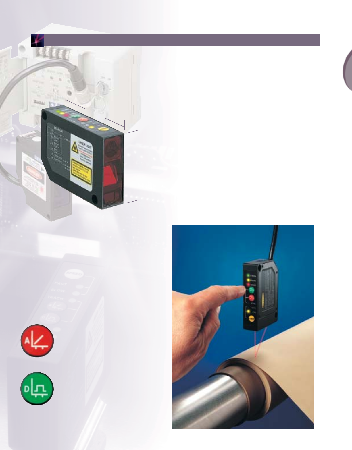
Unique,*self-contained design replaces large, cumbersome systems.
Laser gauging sensors are typically large, two-piece systems, and are difficult to
use. The new Banner L-GAGE has changed all that with a completely self-contained,
12 to 30V dc patent-pending design measuring only 55 mm X 82 mm X 20 mm
82 mm
(3.2")
55mm
(2.2")
(2.2" X 3.2" X 0.8"). By eliminating the need for a separate controller, the
one-piece L-GAGE is easier to wire, decreases setup time and conserves valuable
production space, with the added bonus of superior performance.
*Patent pending
Ultra-precise & accurate, with both analog & discrete outputs.
Advanced digital signal processing algorithms make the L-GAGE Class 2 modulated
visible laser gauging sensor a powerhouse of performance for a wide range of
measurement applications. It features an outstanding maximum resolution of
3 µm (0.0001"). It’s ultra-narrow effective beam resolves precision distance, height
or thickness measurement and gauging applications, including robot arm
calibration, wafer profiling, diameter or thickness measurement, and assembly
dimension inspection, to name only a few.
A price point as sharp as its laser emitter.
Now you can upgrade to laser technology for the same cost as
a contacting sensor. L-GAGE sensors are the first in their category
to break the $1,000 price barrier, providing an economical and
highly accurate solution at a much lower cost. Previously
cost-prohibitive applications can now be solved with ease. And
because L-GAGE sensors do not contact the parts they measure,
they can be used with moving processes, hot parts and sticky
parts. They also include measuring features that are unavailable
on contacting probes, giving the L-GAGE sensors a distinct
advantage in performance as well as price.
Infinitely more flexible.
L-GAGE sensors are vastly more flexible and
easier to program than currently-available
gauging sensors. Why buy an inflexible fixedrange laser sensor when the more-advanced
L-GAGE lets you pick the exact range you need
with the push of a button? And you get both
discrete (switched) and analog outputs in the
same unit, each independently programmable.
It’s a better solution for all your applications. For
additional flexibility, analog units are available
with either 4 to 20 mA or 0 to10V outputs.
2
Page 3
L-GAGE
L-GAGE™: The world’s first teachable laser sensor.
(2.9" to 4.9")
™
: The world’s first teachable laser sensor.
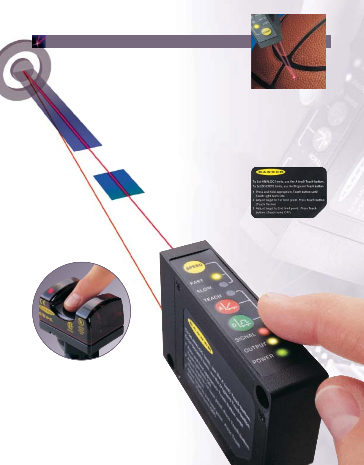
Define your own custom sensing window
by simply pushing a button.
Unlike older, inflexible, fixed-range technology, Banner’s
unique TEACH-mode programming allows you to set your own
75 mm to 125 mm
custom-sized sensing windows, and place them anywhere within
either a 45 mm to 60 mm (1.8" to 2.4") or 75 mm to 125 mm
(2.9" to 4.9") range using a single push button. One
L-GAGE sensor can be easily programmed to provide
an analog output, discrete output, or both
simultaneously with independently controlled
sensing window limits.
45 mm to 60 mm
(1.8" to 2.4")
Automatic gain control.
L-GAGE sensors feature Automatic
Gain Control (AGC) to automatically
compensate for varying colors,
helping to minimize linearity errors
and false triggering associated with
conventional laser sensors.
Remote programming.
For maximum convenience and easier access
for programming hard-to-reach sensors,
TEACH-mode programming can also be
accomplished from a remote location using
an external switch, computer or controller.
The integral key pad may be locked remotely,
providing added security by eliminating
possible tampering with sensor adjustments.
Easy as 1, 2, 3!
Simple programming instructions
(three short sentences) are printed
on the side of the L-GAGE for
permanent, easy access.
3
Page 4

L-GAGE
L-GAGE™: Advanced features help you solve more applications.
™
: Advanced features help you solve more applications.
Exclusive scalable analog output.
Unlike conventional gauging sensors, and available only from
Banner,
L-GAGE sensors allow you to automatically scale the
analog output over your desired sensing window. This unique
feature speeds setup and allows for maximum resolution in electricallynoisy environments. Unique Auto-Zero feature allows you to easily set a
sensing distance set point centered within a 10 mm wide window.
Fast LED:
1.0 ms response
Programmable response times.
Output response is programmable to three speeds,
one, 10, and 100 milliseconds, by simply pushing a button.
You instantly get the response time that works with your
Both LEDs:
10 ms response
Slow LED:
100 ms response
machine cycle speeds.
Advanced diagnostics.
L-GAGE sensors keep you
constantly informed of
operating status throughout
programming and operation.
Sensors also include an alarm
output for signal saturation;
discrete output can be
programmed to detect a
missing target.
Yellow fast/slow LEDs indicate
response time.
Tri-color (red, green, yellow)
TEACH LED indicates sensor is
ready for programming each
limit (analog, discrete, or both
analog and discrete).
Analog Teach button.
Ambient light immunity.
With its modulated laser beam and narrow
optical band-pass filter, the L-GAGE is
highly immune to ambient light,
including high-energy factory lighting.
Protected circuitry.
Integral circuitry protects L-GAGE sensors
from reverse polarity, over voltage, and
transient voltage.
Durable construction.
Rugged L-GAGE sensors have a die-cast
zinc alloy housing, with an aluminum
top cover and an acrylic lens cover.
They are rated IP67 and NEMA 6, and
have an operating temperature range
of -10° to +50°C (+14° to +122°F).
Discrete Teach button.
Red LED indicates target is in the
sensing window and the condition
of the received light signal.
Yellow LED indicates when the
discrete load output is conducting.
Green LED indicates Power ON
and flashes to indicate Output
Overloaded and disabled laser.
Pre-wired or quick-disconnect, 10 to 30V dc.
L-GAGE sensors are available with a 2 m (6.5') or 9 m
(30') attached, 8-conductor PVC potted-in cable, or an 8-pin
Euro-style quick disconnect pigtail connector that allows easy sensor
installation and removal. Keyed connectors prevent wiring errors.
4
Page 5

L-GAGE
RADIANT POWER 0.15 mW
8KHz 8-16% DUTY CYCLE
660 - 680 nm
COMPLIES WITH 21 CFR
1040.10 AND EN60825-1:1994
DO NOT STARE INTO BEAM
CLASS 2 LASER PRODUCT
LASER LIGHT
Avoid exposure -
laser light emitted
from his aperture
T
E
A
C
H
S
L
O
W
F
A
S
T
P
O
W
E
R
O
U
T
P
U
T
S
I
G
N
A
L
S
P
E
E
D
A
D
RADIANT POWER 0.15 mW
8KHz 8-16% DUTY CYCLE
660 - 680 nm
COMPLIES WITH 21 CFR
1040.10 AND EN60825-1:1994
DO NOT STARE INTO BEAM
CLASS 2 LASER PRODUCT
LASER LIGHT
Avoid exposure -
laser light emitted
from his aperture
T
E
A
C
H
S
L
O
W
F
A
S
T
P
O
W
E
R
O
U
T
P
U
T
S
I
G
N
A
L
S
PE
E
D
A
D
RADIANT POWER 0.15 mW
8KHz 8-16% DUTY CYCLE
660 - 680 nm
COMPLIES WITH 21 CFR
1040.10 AND EN60825-1:1994
DO NOT STARE INTO BEAM
CLASS 2 LASER PRODUCT
LASER LIGHT
Avoid exposure -
laser light emitted
from his aperture
T
EA
C
H
S
L
O
W
F
A
S
T
P
O
W
E
R
O
U
T
P
U
T
S
IG
N
A
L
S
P
E
E
D
A
D
T
o
S
e
t
A
N
A
L
O
G
l
i
m
i
t
s
,
u
s
e
t
h
e
A
(
r
e
d
)
T
e
a
c
h
b
u
t
t
o
n
.
T
o
S
e
t
D
I
S
C
R
E
T
E
l
i
m
i
t
s
,
u
s
e
t
h
e
D
(
g
r
e
e
n
)
T
e
a
c
h
b
u
t
t
o
n
.
1
P
r
e
s
s
a
n
d
h
o
l
d
a
p
p
r
o
p
r
i
a
t
e
T
e
a
c
h
b
u
t
t
o
n
u
n
t
i
l
T
e
a
c
h
l
i
g
h
t
t
u
r
n
s
O
N
.
2
A
d
j
u
s
t
t
a
r
g
e
t
t
o
1
s
t
l
i
m
i
t
p
o
i
n
t
.
P
r
e
s
s
T
e
a
c
h
b
u
t
t
o
n
.
(
T
e
a
c
h
f
l
a
s
h
e
s
)
3
A
d
j
u
s
t
t
a
r
g
e
t
t
o
2
n
d
l
i
m
i
t
p
o
i
n
t
.
P
r
e
s
s
T
e
a
c
h
b
u
t
t
o
n
.
(
T
e
a
c
h
t
u
r
n
s
O
F
F
)
TEACH
SLOW
FA
ST
P
O
W
E
R
OUTPUT
S
I
G
N
A
L
SPEED
A
D
T
o
S
e
t
A
N
A
L
O
G
l
i
m
i
t
s
,
u
s
e
t
h
e
A
(
r
e
d
)
T
e
a
c
h
b
u
t
t
o
n
.
T
o
S
e
t
D
I
S
C
R
E
T
E
l
i
m
i
t
s
,
u
s
e
t
h
e
D
(
g
r
e
e
n
)
T
e
a
c
h
b
u
t
t
o
n
.
1
P
r
e
s
s
a
n
d
h
o
l
d
a
p
p
r
o
p
r
i
a
t
e
T
e
a
c
h
b
u
t
t
o
n
u
n
t
i
l
T
e
a
c
h
l
i
g
h
t
t
u
r
n
s
O
N
.
2
A
d
j
u
s
t
t
a
r
g
e
t
t
o
1
s
t
l
i
m
i
t
p
o
i
n
t
.
P
r
e
s
s
T
e
a
c
h
b
u
t
t
o
n
.
(
T
e
a
c
h
f
l
a
s
h
e
s
)
3
A
d
j
u
s
t
t
a
r
g
e
t
t
o
2
n
d
l
i
m
i
t
p
o
i
n
t
.
P
r
e
s
s
T
e
a
c
h
b
u
t
t
o
n
.
(
T
e
a
c
h
t
u
r
n
s
O
F
F
)
TEACH
SLOW
FA
ST
P
O
W
E
R
OUTPU
T
S
I
G
N
A
L
SPEED
A
D
T
o
S
e
t
A
N
A
L
O
G
li
m
i
t
s
,
u
s
e
t
h
e
A
(
r
e
d
)
T
e
a
c
h
b
u
t
t
o
n
.
T
o
S
e
t
D
I
S
C
R
E
T
E
l
i
m
i
t
s
,
u
s
e
t
h
e
D
(
g
r
e
e
n
)
T
e
a
c
h
b
u
t
t
o
n
.
1
P
r
e
s
s
a
n
d
h
o
l
d
a
p
p
r
o
p
r
ia
t
e
T
e
a
c
h
b
u
t
t
o
n
u
n
t
i
l
T
e
a
c
h
l
i
g
h
t
t
u
r
n
s
O
N
.
2
A
d
j
u
s
t
t
a
r
g
e
t
t
o
1
s
t
l
i
m
i
t
p
o
i
n
t
.
P
r
e
s
s
T
e
a
c
h
b
u
t
t
o
n
.
(
T
e
a
c
h
f
l
a
s
h
e
s
)
3
A
d
j
u
s
t
t
a
r
g
e
t
t
o
2
n
d
l
i
m
i
t
p
o
i
n
t
.
P
r
e
s
s
T
e
a
c
h
b
u
t
t
o
n
.
(
T
e
a
c
h
t
u
r
n
s
O
F
F
)
TEACH
SLOW
FAS
T
P
O
W
E
R
OUTPUT
S
I
G
N
A
L
SPEED
A
D
RADIANT POWER 0.15 mW
8KHz 8-16% DUTY CYCLE
660 - 680 nm
COMPLIES WITH 21 CFR
1040.10 AND EN60825-1:1994
DO NOT STARE INTO BEAM
CLASS 2 LASER PRODUCT
LASER LIGHT
Avoid exposure -
laser light emitted
from his aperture
T
E
A
C
H
S
L
O
W
F
A
S
T
P
O
W
E
R
O
U
T
P
U
T
S
I
G
N
A
L
S
P
E
E
D
A
D
P
U
T
4 mm
20 mm
12 mm
28 mm
T
E
A
C
H
S
L
O
W
F
A
S
T
P
O
W
E
R
O
U
T
P
U
T
S
I
G
N
A
L
S
P
E
E
D
A
D
T
o S
e
t A
N
A
L
O
G
lim
i
t
s,
u
s
e th
e
A
(re
d
) T
e
a
ch
b
u
tto
n.
To
S
et
D
I
S
C
R
E
T
E
li
m
its
, us
e
t
he
D
(g
re
e
n)
T
eac
h
b
u
t
to
n
.
1P
re
s
s
a
n
d h
o
ld
a
pp
ro
p
r
ia
te
T
ea
ch
b
ut
to
n
u
nt
il
T
e
a
c
h
lig
ht
tur
n
s
O
N
.
2A
d
ju
st
ta
rg
et to
1
st
li
m
i
t p
oi
nt
. P
re
s
s T
ea
c
h
b
u
tto
n.
(T
e
ac
h
flas
h
e
s
)
3A
d
ju
st ta
rg
e
t to
2
n
d
lim
it
po
i
nt.
P
re
ss
Te
a
c
h
b
u
tto
n
. (T
e
a
ch
t
ur
ns
O
F
F
)
T
E
A
C
H
S
L
O
W
F
A
S
T
P
O
W
E
R
O
U
T
P
U
T
S
I
G
N
A
L
S
P
E
E
D
A
D
T
o
S
e
t
A
N
A
L
O
G
l
im
its
, u
se
t
he
A
(re
d)
Te
a
c
h
b
utt
on
.
To
S
e
t D
IS
C
R
E
TE
l
im
it
s, u
s
e
t
h
e
D
(gr
ee
n
) T
e
a
ch
bu
t
t
on
.
1P
res
s an
d
h
old
a
p
pr
op
ria
t
e
T
e
a
ch
b
u
tto
n
u
n
t
il
T
ea
c
h
li
gh
t t
u
rns
O
N
.
2A
d
ju
st t
a
rg
e
t to
1
s
t l
im
it
p
oi
n
t.
Pre
s
s
T
e
a
c
h
b
u
tto
n
. (T
e
a
c
h
fla
s
h
e
s)
3A
dj
u
st
tar
ge
t
to
2n
d
li
m
i
t po
i
nt.
P
r
e
ss
Te
a
c
h
b
ut
t
on
. (
T
ea
ch
tu
rn
s O
FF
)
T
E
A
C
H
S
L
O
W
F
A
S
T
P
O
W
E
R
O
U
T
P
U
T
S
I
G
N
A
L
S
P
E
E
D
A
D
T
o
S
e
t
A
N
A
L
O
G
l
im
its
,
us
e
th
e
A
(re
d
) T
e
ac
h
b
ut
ton
.
T
o
Se
t
D
IS
C
RE
T
E lim
it
s
, u
se
th
e
D
(
g
re
en
)
T
ea
c
h
b
ut
ton
.
1P
re
ss
a
nd
h
o
ld
ap
p
ro
p
ria
te
T
e
a
ch
b
u
tto
n
u
nt
i
l
T
e
ach
l
ig
ht t
ur
n
s
O
N
.
2A
dj
us
t
tar
ge
t t
o
1
st
lim
it
po
in
t.
Pr
es
s
T
e
a
ch
b
u
tt
on
.
(T
ea
c
h
fla
sh
es
)
3A
dj
us
t ta
rg
e
t
to
2
nd
lim
it p
o
in
t
. P
re
s
s T
e
a
c
h
b
utto
n
. (T
e
ach
tu
rn
s O
F
F)
RADIANT POWER 0.15 mW
8KHz 8-16% DUTY CYCLE
660 - 680 nm
COMPLIES WITH 21 CFR
1040.10 AND EN60825-1:1994
DO NOT STARE INTO BEAM
CLASS 2 LASER PRODUCT
LASER LIGHT
Avoid exposure -
laser light emitted
from his aperture
T
E
A
C
H
S
L
O
W
F
A
S
T
P
O
W
E
R
O
U
T
P
U
T
S
I
G
N
A
L
S
P
E
E
D
A
D
RADIANT POWER 0.15 mW
8KHz 8-16% DUTY CYCLE
660 - 680 nm
COMPLIES WITH 21 CFR
1040.10 AND EN60825-1:1994
DO NOT STARE INTO BEAM
CLASS 2 LASER PRODUCT
LASER LIGHT
Avoid exposure -
laser light emitted
from his aperture
T
E
A
C
H
S
L
O
W
F
A
S
T
P
O
W
E
R
O
U
T
P
U
T
S
I
G
N
A
L
S
P
E
E
D
A
D
RADIANT POWER 0.15 mW
8KHz 8-16% DUTY CYCLE
660 - 680 nm
COMPLIES WITH 21 CFR
1040.10 AND EN60825-1:1994
DO NOT STARE INTO BEAM
CLASS 2 LASER PRODUCT
LASER LIGHT
Avoid exposure -
laser light emitted
from his aperture
T
E
A
C
H
S
L
O
W
F
A
S
T
P
O
W
E
R
O
U
T
P
U
T
S
I
G
N
A
L
S
P
E
E
D
A
D
A
F
F - (A+B) = Thickness
B
L-GAGE™Laser Sensor Applications
™
Laser Sensor Applications
WOOD PROFILING
Objective: Profile wood moldings; inspect milled dimensions.
Sensor: L-GAGE model LG10A65NU
Operation: The L-GAGE, with a 100 mm standoff distance and
a 50 mm measuring window, can accurately profile
a wide variety of wooden moldings in milling
applications. Not only is the L-GAGE fast and
accurate, it is also very tolerant of changing wood
colors. For example, changing from dark walnut to
light ash requires no change in sensor configuration.
RUN-OUT INSPECTION OF WHEEL CASTING
Objective: Prior to machining, inspect a wheel casting to ensure
that six critical dimensions are within tolerance.
Sensor: L-GAGE model LG5A65PU
Operation: Wheel castings slide into a rotating fixture beneath six
stationary L-GAGE sensors. Each L-GAGE is positioned
so that a nominal casting is at the center of the sensor’s
measuring window. The 0 to 10V dc outputs of all six
sensors are fed into a PLC, which records maximum runout.
The LG5A, with its wide beam diameter, was selected for
best output stability on a rough casting surface. The L-GAGE
non-contact sensor eliminates frequent sensor replacement
and recalibration.
S
I
G
N
A
L
D
1040.10 AND EN60825-1:1994
COMPLIES WITH 21 CFR
660 - 680 nm
8KHz 8-16% DUTY CYCLE
RADIANT POWER 0.15 mW
A
T
E
A
C
H
from his aperture
CLASS 2 LASER PRODUCT
laser light emitted
DO NOT STARE INTO BEAM
Avoid exposure -
S
LO
LASER LIGHT
W
F
A
S
T
S
P
E
E
D
THICKNESS MEASUREMENT OF PLYWOOD
Objective: Measure thickness at three points across the width
of a sheet of plywood
Sensor: L-GAGE model LG10A65NU
Operation: Three pairs of L-GAGE sensors are set up across a sheet
of laminate. Thickness at each location is determined
by subtracting the distance from each sensor to the
plywood from the distance between the pair of sensors:
t = F - (A+ B), where A is the top distance, B is the
bottom distance, and F is the fixed distance between the
sensors in each pair.
5
Page 6

L-GAGE
L-GAGE™Laser Sensors Model Selection & Accessories
™
Laser Sensors Model Selection & Accessories
4-20 mA current analog output
■
Model Number Part Number Range Focal Point Resolution* Cables Analog Output Discrete Output
LG5A65NI
LG5A65NIQ
LG5A65PI
LG5A65PIQ
LG5A65NU
LG5A65NUQ
LG5A65PU
LG5A65PUQ
LG5B65NI
LG5B65NIQ
LG5B65PI
LG5B65PIQ
LG5B65NU
LG5B65NUQ
LG5B65PU
LG5B65PUQ
LG10A65NI
LG10A65NIQ
LG10A65PI
LG10A65PIQ
LG10A65NU
LG10A65NUQ
LG10A65PU
LG10A65PUQ
* Best resolution for analog and discrete outputs determined with a white ceramic test surface at the specified distance, with the sensor response speed set for slow (100 milliseconds).
** For 9 m (30') cable assembly, add w/30 to model number.
54086
54087
54089
54090
57571
57572
57565
57566
55964
55968
55966
55969
57574
57575
57568
57569
54092
54093
54095
54096
57577
57578
57580
57581
45-60 mm (1.8"-2.4")
75-125 mm (3.0"-4.9")
70 mm (2.8")
53 mm (2.1")
For small
object detection
180 mm (7.1")
<3 µm (0.0001")
<10 µm (0.0004")
@ 100 mm
0-10V dc voltage analog output
■
6" (15.2 cm) 8-pin Euro QD
6" (15.2 cm) 8-pin Euro QD
6" (15.2 cm) 8-pin Euro QD
@ 50 mm
6" (15.2 cm) 8-pin Euro QD
6" (15.2 cm) 8-pin Euro QD
6" (15.2 cm) 8-pin Euro QD
6" (15.2 cm) 8-pin Euro QD
6" (15.2 cm) 8-pin Euro QD
6" (15.2 cm) 8-pin Euro QD
6" (15.2 cm) 8-pin Euro QD
6" (15.2 cm) 8-pin Euro QD
6" (15.2 cm) 8-pin Euro QD
2m (6.5') 8-wire**
2m (6.5') 8-wire**
2m (6.5') 8-wire**
2m (6.5') 8-wire**
2m (6.5') 8-wire**
2m (6.5') 8-wire**
2m (6.5') 8-wire**
2m (6.5') 8-wire**
2m (6.5') 8-wire**
2m (6.5') 8-wire**
2m (6.5') 8-wire**
2m (6.5') 8-wire**
NPN (sinking)
4-20ma Sourcing
PNP (sourcing)
NPN (sinking)
0-10V dc Sourcing
PNP (sourcing)
NPN (sinking)
4-20ma Sourcing
PNP (sourcing)
NPN (sinking)
0-10V dc Sourcing
PNP (sourcing)
NPN (sinking)
4-20ma Sourcing
PNP (sourcing)
NPN (sinking)
0-10V dc Sourcing
PNP (sourcing)
L-GAGE Mounting Bracket Model SMBLG (Part Number 55815)
Type 304 stainless steel mounting bracket is corrosion resistant and provides up to 42° of vertical adjustment
and up to 40° of horizontal adjustment. This attractively designed unit enhances the appearance of your
equipment and saves you time and money through reduced installation time and lower total installed cost.
Custom brackets can be designed for your unique applications.
L-GAGE Mounting Bracket Model SMBLGA (Part Number 55906)
Similar to Model SMBLG above but also provides spring-loaded precision adjustment screws enabling the
installer to make extremely accurate adjustments for small targets or long range applications. Type 304
stainless steel. Request the Banner Sensor Catalog (P/N 99000) or CD ROM (P/N 99100) for other available
models. Custom brackets can be designed for your unique applications.
Euro-style Quick Disconnect Cable Model MQDC-830 (Part Number 57595)
Straight 8-pin cable, 9 m (30') length. Electrically shielded design with PUR jacket and polyurethane
connector body with nickel plated brass coupling nut.
6
Page 7

L-GAGE
L-GAGE™Laser Sensor Specifications & Dimensions
™
Laser Sensor Specifications & Dimensions
Supply Specifications:
Supply Voltage:12 to 30V dc, (10% maximum ripple); 50mA max at 24Vdc
(exclusive of load).
Sensing Supply Protection Circuitry: Protected against reverse polarity,
over voltage, and transient voltages.
Delay at Power-up:1.25 second.
Sensing Characteristics:
Sensing Beam: 670 nm visible red IEC and CDRH Class 2 laser; 0.20 mW
maximum radiant output power.
Range: LG5: 45.0 to 60.0 mm (1.77" to 2.36"); LG10: 75.0 to 125.0 mm (2.95" to 4.92").
Minimum Window Size (Analog or Discrete): LG5: 1.5 mm (0.06");
LG10: 5 mm (0.2").
Analog Resolution and Repeatability of Discrete Trip Point:
LG5 System response speed set at fast: <40 µm (0.0016") @ 50 mm (2").
System response speed set at medium: <12 µm (0.0005") @ 50 mm (2").
System response speed set at slow: <3 µm (0.0001") @ 50 mm (2").
LG10 System response speed set at fast: <150 µm (0.006") @ 100 mm (2").
System response speed set at medium: <50 µm (0.0016") @ 100 mm (2").
System response speed set at slow: <10 µm (0.0016") @ 100 mm (2").
Analog Linearity:
LG5 ±60 µm (±0.002") over 45 to 60 mm (1.77" to 2.36") sensing window.
±10 µm (±0.0004") over 49 to 51 mm (1.93" to 2.00") sensing window.
LG10 ±200 µm (±0.008") over 75 to 125 mm (2.95" to 4.92") sensing window.
±20 µm (±0.0008") over 95 to 100 mm (3.74" to 3.93") sensing window.
55.3 mm
(2.18")
4.6 mm
(0.18")
45.5 mm
(1.79")
20.2 mm (0.80")
ER
T
82.3 mm
(3.24")
POW
O
U
T
P
U
SIGNAL
RADIA
8KH
660 - 680 nm
C
1040.10 AN
68.3 mm
(2.69")
D
O
MP
D
C
NT P
z 8-16%
LIES W
A
C
H
L
A
S
E
O
N
R
O
T
L
S
A
S
T
S
A
2
R
L
A
S
E
Avoid exposure laser light em
from
his aperture
OW
ER 0.15 m
D
UTY CYCLE
ITH 21 CFR
D EN60825-1:1994
POWER
OUTPUT
SIGNAL
D
A
T
E
A
C
S
H
L
O
W
S
T
L
A
S
D
E
O
N
R
C
O
L
T
L
A
S
S
I
T
S
G
A
2
R
H
E
L
A
IN
T
S
T
E
O
R
B
A
P
v
E
R
o
A
O
id
M
D
la
e
U
C
s
x
e
T
p
r lig
o
s
fro
u
h
R
re
m
t e
A
-
D
h
m
is
IA
8
it
a
K
N
te
H
p
T
d
z
e
P
6
8
r
6
tu
O
-1
0
r
W
- 6
e
6
C
%
E
O
8
R
D
0
M
0
nm
U
1
P
.1
T
0
L
5
4
Y
I
E
m
0
C
.1
S
W
Y
W
0
C
A
IT
L
N
E
H
D
2
E
1
N
C
6
F
0
8
R
25
-1
:1
9
9
4
T
E
A
SLO
W
F
A
ST
SPEED
L
IG
H
E
IN
T
T
O
R
B
P
E
R
A
O
M
D
U
C
T
itted
W
F
A
S
P
E
E
D
23.9 mm
(0.94")
Beam Dimensions
Y
X
Emitted Light
Received Light
19.1 mm
(0.75")
9.3 mm
(0.37")
Hysteresis (Discrete Output): LG5: < 0.2 mm (0.008"); LG10 <1 mm (0.04").
Color Sensitivity: LG5: <75 µm (0.003") (typical) for white or dark gray ceramic target;
LG10: < 100 µm (0.01") (typical) for white or dark gray ceramic target.
Temperature Drift: LG5: ±7 µm /°C; LG10: ±25 µm /°C.
Output Specifications:
Output Configurations: Discrete (switched) output: SPST solid-state switch
(choose NPN or PNP models).
Analog output: Current models: 4 to 20 milliamp current
sourcing; Voltage models: 0 to10V dc current sourcing.
Alarm output: SPST Solid-state switch (NPN or PNP
depending on discrete output model).
Output Ratings: Discrete (switched): 100 mA maximum.
Analog output: Current models: 1KΩ max @ 24V dc;
Voltage models: 2.5KΩ minimum load impedance.
Alarm output: 100 mA maximum.
Output Protection: Discrete outputs are protected against continuous overload
and short circuit.
Output Response Time: Discrete output: system response speed set at fast:
2.0 milliseconds ON and OFF; system response speed set
at medium: 10 milliseconds ON and OFF; system
response speed set at slow: 100 milliseconds ON and OFF.
Analog output (-3 dB): fast: 450 Hz (1 millisecond);
medium: 45 Hz (10 millisecond); slow: 4.5 Hz
(100 millisecond).
L-GAGE Beam Dimensions (typical)
Focal
Point* Width (X) Height (Y)
Distances
45 mm 0.3 mm 0.5 mm
53 mm
(2.1")
53 mm 0.1 mm 0.1 mm
60 mm 0.3 mm 0.5 mm
45 mm 0.6 mm 0.9 mm
70 mm
(2.8")
53 mm 0.4 mm 0.6 mm
60 mm 0.3 mm 0.4 mm
75 mm 1.1 mm 1.5 mm
180 mm
(7.1")
100 mm 0.8 mm 1.1 mm
125 mm 0.6 mm 0.8 mm
* The Focal Point is the distance measured from the lens (front of sensor) at which
the diameter of the laser image is smallest.
Beam Beam
7
Page 8

Banner: Industry’s number one supplier of sensors & machine safety products.
Banner: Industry’s number one supplier of sensors & machine safety products.
When you buy your sensors and machine
safety products from Banner, you gain the
confidence of dealing with the industry’s
largest, most knowledgeable and experienced
photoelectric company. We have the broadest
line of products and the most advanced
manufacturing capabilities in the industry.
We can handle any size order, large or
small, utilizing the most advanced
manufacturing capabilities.
We can deliver any of more than 15,000
different products in just three days–most
can ship within hours!
Just as important, we have the largest
photoelectric sales and support network
in the industry, backed by the world’s finest
application engineers. With our global sales
support network, we’re close by wherever
you’re located, and we’re ready to help you
with your applications, plus give you
excellent service support. When you add it up,
you’ll find the best value in Banner products.
Visit Banner On-Line at
www
.baneng.com
• Complete product information for:
–
Photoelectric sensors
–
Measurement and
inspection sensors
–
Machine safety products
• Up-to-date “What’s New” page.
• Complete descriptions for each product,
with links to product data sheets and
dimension drawings.
• Product catalogs, specifier’s guides,
and product brochures available for
immediate download or email request.
•
Documents available in multiple languages.
For more information or
applications assistance:
Call 1.888.3.SENSOR
(1.888.373.6767)
The Banner Photoelectric
Sensors Catalog & CD ROM.
The industry’s most complete catalog;
more than 700 pages of detailed
product and technical information
on more than 12,000 photoelectric
sensors. Simple selection charts
make specifying the
correct sensor easier
than ever. Call, write,
or email for your
copy today, P/N
99000; CD ROM,
P/N 99100.
Worldwide Representation.
• Australia
• Argentina
• Austria
• Belgium
• Brazil
• Canada
• Chile
• China
• Colombia
• Costa Rica
• Czech Republic
• Denmark
• Egypt
• Estonia
• Finland
• France
• Germany
• Greece
• Hong Kong
• Hungary
• Iceland
• India
• Indonesia
• Ireland
• Israel
• Italy
• Japan
• Korea
• Latvia
• Lithuania
• Luxembourg
• Malaysia
• Mexico
The Banner Machine Safety
Products Catalog & CD ROM.
A complete catalog of Machine Safety
Products including Banner’s extensive
line of safety light screen controllers,
emitters and receivers. Also included
are Banner’s two-hand anti-tiedown
controls and full line of safety interlock
switches and E-stop
safety modules.
Call, write, or
email for your
copy today, P/N
99500; CD ROM,
P/N 99100.
• Netherlands
• New Zealand
• Norway
• Pakistan
• Peru
• Philippines
• Poland
• Portugal
• South Africa
• Russia/CIS
• Singapore
• Slovakia
• Spain
• Sweden
• Switzerland
• Taiwan
• Thailand
• Turkey
• United
Kingdom
• Uruguay
• Venezuela
Banner Engineering Corporation, P.O. Box 9414, Minneapolis, MN 55440 U.S.A.
Phone 612.544 .3164 Fax 612.544 .3213 www.baneng.com Email: sensors@baneng.com
PRINTED IN U.S.A. Copyright, 1999 Banner Engineering Corporation P/N 59987
 Loading...