

Page 1
EZ-LIGHT
Indicator Lights and
Pick-to-Light Sensors
SECOND EDITION
™
Page 2
Banner lights the way for Lean manufacturing.
A level of reliable operator guidance or simple indication. Easily installs and operates with
virtually no maintenance—using as little energy as possible.
2
Page 3
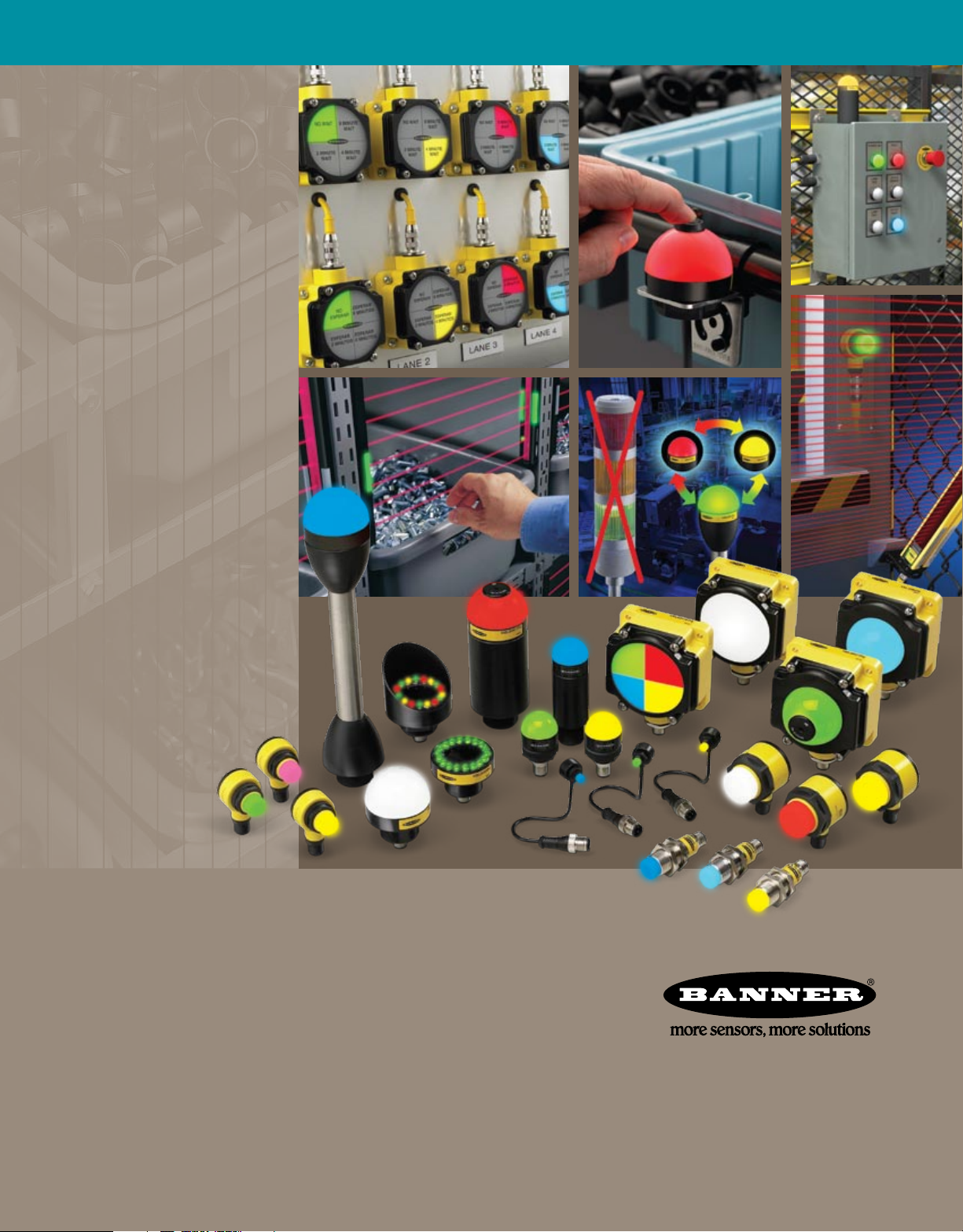
Beyond Andon: EZ-LIGHT™, the next generation of visual indication
Banner’s EZ-LIGHT™ family of products provides numerous solutions for visual process management
and operator guidance. From innovative multi-color indicator lights to pick-to-light and sequence-guided
assembly, error-proofing and productivity solutions, EZ-LIGHT replaces conventional indicators and devices,
providing process refinement in ways never before possible. Incorporating sensor technology into operator
guidance indicators ensures virtually error-free assembly and the highest levels of productivity.
EZ-LIGHT™ solutions
•
Deliver real-time operational status indication for workers and supervisors
• Eliminate false readings from stray light; always appear gray when off
• Prompt operators and guide sequential part selection
• Verify correct action with sensor or push-button indication
• Offer point sensing or arrays for wide area pick-to-light
• Feature compatibility with PLC or other logic-level control outputs
• Install quickly and easily with pre-wired or quick-disconnect options
• Promote high visibility from all angles
• Reduce costs, defects and Muda (waste)
• Improve plant flow, productivity and efficiency
3
Page 4
EZ-LIGHT™ Product Features
EXAMPLE APPLICATIONS
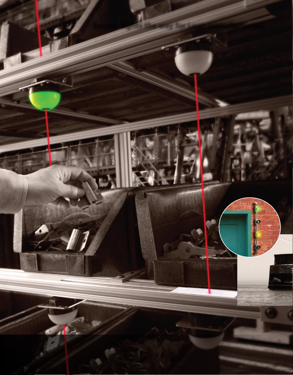
Process Status
Overhead Door & Gate Status
Vehicle Position Indicator
for Outdoor Applications
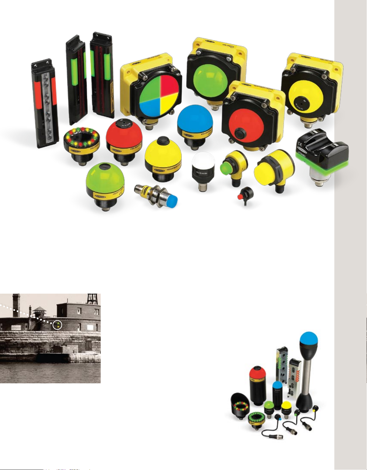
A complete range of models and styles
• Smart General-Purpose indicators displaying up to three colors in one device
• Multi-Function indicators displaying up to five colors with solid, flashing or
sequenced flashing cycles
• Sensor Emulator indicators displaying sensor status where sensor visibility is
obscured or limited
• Segmented indicators delivering simultaneous one, two, three or four color
display for multiple status indication
• Daylight Visible indicators generating intense levels of light output for
outdoor applications or areas of high ambient light
• Audible indicators combining visible light indication with audio alerts
• Pick-to-Light indicators and sensors reducing assembly and picking errors,
improving product quality while reducing costs
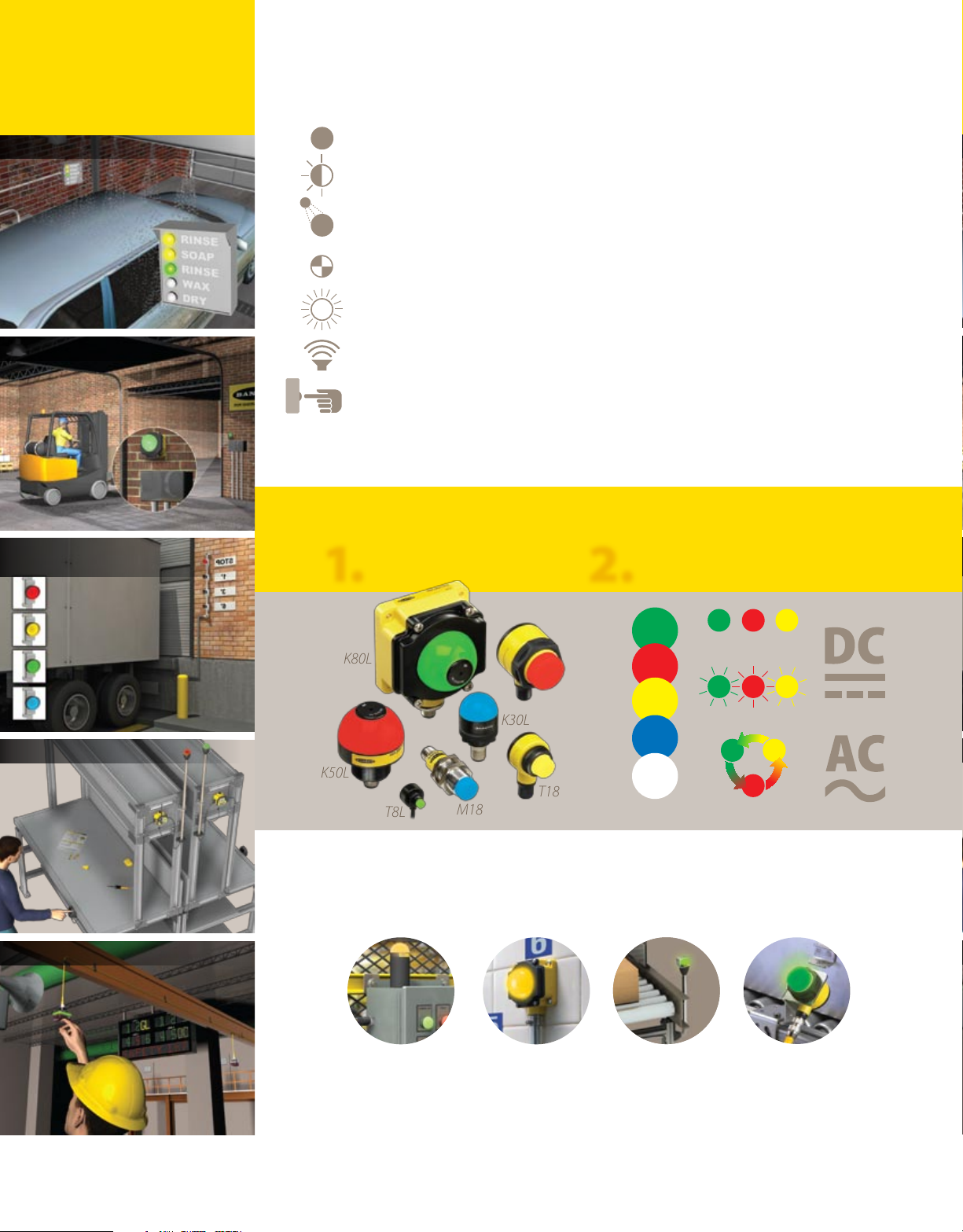
Specify your EZ-LIGHT™ in 4 Easy Steps
1. 2.
Choose your housing Choose color, function, voltage
Call for Service
Line Problem Call
ON steady
Flashing
Alternating
K50L
K80L
T8L
T30
K30L
T18
M18
Mounting solutions for any application
• Installs quickly with a single drilled hole and many mounting options
Cabinet mounting Surface mount Standoff pipe and Base, nose and
protective brackets DIN-mount brackets
• Includes models with 22 or 30 mm threaded base for panel mounting
• Features mounting hubs for both EMT and gas/water pipe mounting (K50L model)
• Offers models and accessories for machine- and wall-mounting, as well as
ceiling suspension
4
Page 5

Robust, durable, green and Lean design
• Completely self-contained operation—no controller needed
• Extremely long-lasting LED technology providing >100,000
hours (11 years continuous) working life
• Very low power consumption: <1W for most DC models, <2W for
AC models—compare to competitive units that consume up to 15W
• Ergonomic, lean shape that sheds debris and moisture
• No hook hazards for moving equipment and personnel—unlike conventional
stack lights
EXAMPLE APPLICATIONS
Process Inspection Indicator
• Robust IP67/IP69K-rated, water- and oil-tight industrial housings for direct
machine mounting
• Rugged, compact design that is cost-effective and easy-to-install
• Shock, vibration and impact resistant
• Compatibility with AS-i modules and fieldbus splitter boxes
Choose input type
3. 4.
- OR -
Choose your connection
Attached Cable PVC or PUR Pigtail QD
Integral QD Terminal-Wired
4-Color Point-of-Use Indicator
Remote Level Indicator
Cabinet-Mount Status Indication
Numerous color display options
• Single devices displaying up to 5 colors each—replacing multiple indicators
to save panel space and costs
• Models with 31 functions for steady, flashing or alternating colors
• Excellent but non-aggressive light brilliance and visibility for operators
Elevated Indication
with Audible Alert
5
Page 6

EZ-LIGHT™ Operator Indicator Lights
80.8 mm
109.5 mm
66.3 mm
ø 50 mm
45 mm
56.8 mm
63.7 mm
61 mm
ø 30 mm
58 mm
16.5 mm
Housing
Description
Maximum Colors
in One Housing
Standard Colors
Functions
K80L K50L T30 M18 K30L T18 T8L
50 mm dome or
flat profile
5 5 3 3 3 3 2
General Purpose
ON steady
Sensor Emulator
Remote indicator,
ON steady
Multi-Function
ON steady,
Flashing,
Alternating
Audible
Steady (75 dB)
Loud steady (95 dB)
Pulsed (75 dB)
Segmented
Up to 4 segments
50 mm dome or
flat profile
General Purpose
ON steady
Sensor Emulator
Remote indicator,
ON steady
Multi-Function
ON steady,
Flashing,
Alternating
Audible
Steady (75 dB)
Loud steady (95 dB)
Pulsed (75 dB)
30 mm T-style 18 mm barrel 30 mm dome 18 mm T-style 8 mm T-style
General Purpose
ON steady
Sensor Emulator
Remote indicator,
ON steady
Multi-Function
ON steady,
Flashing,
Alternating
General Purpose
ON steady
Sensor Emulator
Remote indicator,
ON steady
Multi-Function
ON steady,
Flashing,
Alternating
General Purpose
ON steady
Sensor Emulator
Remote indicator,
ON steady
Specifications
Power Requirement
Input
Connection
(depending on number of
colors and functionality)
Mounting Flat or DIN-mount
Construction Thermoplastic Thermoplastic Thermoplastic Nickel-plated brass Thermoplastic Thermoplastic Polycarbonate
Rating
Operating Temperature
18 to 30V dc or
85 to 130V ac
DC: NPN or PNP
AC: 85 to 130V ac
4-, 5- or 8-pin
integral Euro QD
4-, 5- or 8-pin
pigtail Euro QD
Terminal-wired
Audible: IP50
All others: IP67
Audible: -20˚ to +50˚ C
All others: -40˚ to +50˚ C
18 to 30V dc or
85 to 130V ac
DC: NPN or PNP
AC: 85 to 130V ac
4-, 5- or 8-pin
integral Euro QD
4-, 5- or 8-pin
pigtail Euro QD
2 m attached cable
30 mm threaded
base
Audible: IP50
All others: IP67
Audible: -20˚ to +50˚ C
All others: -40˚ to +50˚ C
10 to 30V dc 10 to 30V dc 10 to 30V dc 10 to 30V dc 10 to 30V dc
NPN or PNP NPN or PNP NPN or PNP NPN or PNP NPN or PNP
4- or 5-pin
integral Euro QD
4- or 5-pin
pigtail Euro QD
2 m attached cable
30 mm threaded
nose
4- or 5-pin
integral Euro QD
4- or 5-pin
pigtail Euro QD
2 m attached cable
18 mm threaded
barrel
4-pin
integral Euro QD
4-pin
pigtail Euro QD
2 m attached cable
22 mm threaded
base
IP67 IP67 IP67 IP67 IP67
-40˚ to +50˚ C -40˚ to +50˚ C -40˚ to +50˚ C -40˚ to +50˚ C -40˚ to +50˚ C
6
More information online at bannerengineering.com
Page 7

53.6 mm
33 mm
19.1 mm
15.8 mm
EZ-LIGHT™ Specialty Indicator Lights
80.8 mm
109.5 mm
SEGMENTED AUDIBLE DAYLIGHT VISIBLE
41 mm
K80L K80L/K50L K50LD
50 mm flat profile 50 mm dome 50 mm flat profile
4 4 3
109.5 mm
80.8 mm
66.3 mm
ø 50 mm
ø 50 mm
56.8 mm
49.5 mm
General Purpose
ON steady
Sensor Emulator
Remote indicator,
ON steady
4-pin
integral Euro QD
4-pin
pigtail Euro QD
2 m attached cable
General Purpose
ON steady
Sensor Emulator
Remote indicator,
ON steady
4-pin
pigtail Euro QD
2 m attached cable
Segmented
Up to 4 segments
No segments
Audible
Steady (75 dB)
Loud steady (95 dB)
Pulsed (75 dB)
Daylight Visible
Intense levels of light
output for outdoor
applications
4 segments
Horizontal split
Top half
18 to 30V dc 18 to 30V dc 18 to 30V dc
NPN or PNP NPN or PNP NPN or PNP
5-pin
integral Euro QD
5-pin
pigtail Euro QD
Terminal-wired
K50L: 2 m attached cable
K80L: Terminal-wired
5-pin
integral Euro QD
5-pin
pigtail Euro QD
4-pin
integral Euro QD
4-pin
pigtail Euro QD
2 m attached cable
18 mm threaded
nose
8 mm threaded
nose
Flat or DIN-mount
Thermoplastic Thermoplastic Thermoplastic
IP67 IP50 IP67
-40˚ to +50˚ C -20˚ to +50˚ C -40˚ to +50˚ C
More information online at bannerengineering.com
K80L: Flat or DIN-mount
K50L: 30 mm threaded base
30 mm threaded
base
7
Page 8

EZ-LIGHT™ Pick-to-Light Sensors
ø 50 mm
80.8 mm
72.5 mm 43.2 mm
59.9 mm
16.4 mm
30 mm
30 mm
15 mm
PVA100: 137.8 mm
PVA225: 266.4 mm
PVA300: 341.4 mm
PVA375: 416.6 mm
Two-component
light array
Housing
Description
56.8 mm
K50 K80 VTB PVD PVA
50 mm dome light
indicator with sensor
or push button
109.5 mm
50 mm dome light
indicator with
push button
57.1 mm
Ultra-bright optical
touch button
PVD100: 137.8 mm
PVD225: 266.4 mm
One-component
light array
Job Light
Retro: 2 m
Maximum
Sensing Range
Fixed-Field: 25, 50,
100 mm
— —
Retro: 2 m
Diffuse: 400 mm
Opposed: 2 m
Push-Button: —
Minimum Object
Detection Size
— — —
Retro: 51 to 100 mm
Diffuse: 55 mm
35 mm
Specifications
Power Requirement 12 to 30V dc 12 to 30V dc 12 to 30V dc 12 to 30V dc 12 to 30V dc
Output Configuration
One NPN or PNP &
NO or NC,
depending on
model
One NPN or PNP &
NO or NC,
depending on
model
One NPN or PNP,
depending on
model
One user-selectable
PNP or NPN
One NPN or PNP,
depending on model;
programmable for
light or dark operate
Connection
Mounting
4- or 5-pin
integral Euro QD
4- or 5-pin
pigtail Euro QD
2 m or 9 m
attached cable
30 mm
threaded base
4- or 5-pin
integral Euro QD
4- or 5-pin
pigtail Euro QD
2 m or 9 m
attached cable
Flat or DIN-mount
4- or 5-pin
integral Euro QD
2 m or 9 m
attached cable
30 mm
threaded base
5-pin
pigtail Euro QD
2 m or 9 m
attached cable
4-pin
pigtail Euro QD
2 m
attached cable
Flat mount Flat mount
Black polysulfone or
Construction
Polycarbonate &
nylon
Polycarbonate &
nylon
red polycarbonate
with white
Black painted
aluminum
Black anodized
aluminum
polycarbonate base
Rating
IP69K (depending
on installation)
IP69K (depending
on installation)
IP66; NEMA 4X IP62; NEMA 2 IP62; NEMA 2
Operating Temperature -40˚ to +50˚ C -40˚ to +50˚ C -20˚ to +50˚ C 0˚ to +50˚ C 0˚ to +50˚ C
Data Sheet
2-color: 126441
3-color: 137551
2-color: 126441
3-color: 137551
67570 113230 52088
8
8
More information online at bannerengineering.com
Page 9

EZ-LIGHT™ Accessories
Standoff Pipe and Cabinet Mounting K50LD Sun Shield
SA-M30E12
Ther moplastic
Acetal adapter
and cover
SOP-E12-150SS
(150 mm)
or
SOP-E12-300SS
(300 mm)
stainless steel pipe
SA-E12M30
Ther moplastic
Acetal mounting base
SA-M30M30-75
Ther moplastic
Acetal standof f with
30 mm mounting
base for cabinet
mounting or use
with most 30 mm
brackets
SA-30RL 55X93
Zinc coated, oversized
right-angle legend plate
for identification labels
SA-M22M22-50
Ther moplastic Ac etal
standoff with 22.5 mm
mounting base for
cabinet mounting
SMBE12USS
Stainless s teel
bracket for wall or
other flat surfaces
SA-30RL55X93C
Zinc coated bracket
with strain relief
K50DS
Ther moplastic
Polyester sun shield
Brackets
Right-Angle Swivel Brackets Adapter (22.5 to 18 mm)
SMB8MM
T8L
SMB22A
M18 T18
T30 K50L
SMB18A
SMB30A
M18
SMB18FA
SMB30FA
SA-2218
M18
T18
DIN-Rail
SMBDX80DIN
SMB30RAV K
K30L
T30 T30
K50L
K80LK50L
Quick-Disconnect (QD) Cordsets
4-Pin Euro-Style Splitter 4-Pin Euro-Style 5-Pin Euro-Style 8-Pin Euro-Style 5-Pin Micro-Style
Model Branches Tr unk
(Fema le) (Male)
CSB-M1240M1240 None None
CSB-M1241M1241 2 x 0.3 m 0.3 m
CSB-M1248M1241 2 x 0.3 m 2.5 m
Used with:
• Sensor emulator
Model* Length
MQDC-406 2 m
MQDC-415 5 m
MQDC-430 9 m
Used with:
• General purpose (DC)
• Sensor emulator
• Daylight visible
More information online at bannerengineering.com
Model* Length
MQDC1-506 2 m
MQDC1-515 5 m
MQDC1-530 9 m
Used with:
• 3- or 4-color,
multi-function
• Segmented
• Audible
*For a right-angle cordset, add RA to the model number (example, MQDC- 406RA).
Model* Length
MQDC2S-806 2 m
MQDC2S-815 5 m
MQDC2S-830 9 m
Used with:
• 5-color, multi-function
Model* Length
MQVR 3S-506 2 m
MQVR 3S-515 5 m
MQVR3S-530 9 m
Used with:
• General purpose (AC)
9
9
Page 10

Color*
Housing C1 C2 C3 Input Connection
Color*
Housing C1 C2 C3 Voltage Connection
EZ-LIGHT™ Model Guide
Specify your model in 4 easy steps:
1. Choose your housing
2. Choose your color, function and voltage
3. Choose your input type
4. Choose your connection
General Purpose: DC Models
K50L G R Y P Q P
M18
T18
T30
K30L
K50L
K80L
T8L (1 or 2
color only)
G = Green
R = Red
Y = Yellow
B = Blue
W = White
X = No color
P = PNP (Sourcing)
N = NPN (Sinking)
Blank = K80L: Terminal-wired
All others: 2 m
Q = 4-pin Euro integral QD (except T8L)
QP = 4-pin Euro pigtail QD
Hookup Diagram: HK01
Online Data Sheet:
P/N 130865 (1 color)
P/N 121899 (2 & 3 color)
K50LD K50L K30L
K80L T30 T18 T8L M18
General Purpose: AC Models
*No color: General P urpose and Daylight Visible only
Hookup Diagram: HK02
Online Data Sheet: P/N 134548
K50L G R Y A120 Q
K50L
K80L
G = Green
R = Red
Y = Yellow
B = Blue
W = White
A120 = 120V ac
Blank = 2 m
Q = 5-pin Micro integral QD
Hookup Diagram: HK03
Multi-Function: 3 Color
Color*
Housing C1 C2 C3 Function
Online Data Sheet: P/N 121902
†
Input Connection
K50L G R Y 2 P QP
M18
T30
K50L
K80L
2 = Multi-Function
G = Green
R = Red
Y = Yellow
B = Blue
W = White
Multi-Function: 5 Color
Color*†
Housing C1 C2 C3 C4 C5 Input Connection
P = PNP (Sourcing)
N = NPN (Sinking)
Blank = K80L: Terminal-wired
All others: 2 m
Q = 5-pin Euro integral QD
QP = 5-pin Euro pigtail QD
Hookup Diagram: HK04
Online Data Sheet: P/N 131413
K50L GRYBW P Q P
K50L
K80L
G = Green
R = Red
Y = Yellow
B = Blue
W = White
P = PNP (Sourcing)
N = NPN (Sinking)
Blank = K80L: Terminal-wired
K50L: 2 m
Q = 8-pin Euro integral QD
QP = 8-pin Euro pigtail QD
Hookup Diagram: HK03
Multi-Function: 4 Color
Color*
Housing C1 C2 C3 C4 Function
Online Data Sheet: P/N 137329
†
Input Connection
K50L G R Y B 4 P QP
K50L
K80L
4 = Multi-Function
G = Green
R = Red
Y = Yellow
B = Blue
W = White
Sensor Emulator: 2 Color
Color*
Housing C1 C2 Function Input Connection
P = PNP (Sourcing)
N = NPN (Sinking)
Blank = K80L: Terminal-wired
K50L: 2 m
Q = 5-pin Euro integral QD
QP = 5-pin Euro pigtail QD
Hookup Diagram: HK05
Online Data Sheet: P/N 121900
K50L G Y X7 P QP
T8L
M18
T18
T30
K30L
K50L
K80L
X7 = Sensor Emulator
G = Green
R = Red
Y = Yellow
B = Blue
W = White
P = PNP (Sourcing)
N = NPN (Sinking)
Blank = K80L: Terminal-wired
All others: 2 m
Q = 4-pin Euro integral QD (except T8L)
QP = 4-pin Euro pigtail QD
* Number of colors are determined by C1, C2, C3, C4, C5 specified in model guides.
General-purpose models (DC only): For less than 3 colors, use X as a model placeholder (example, K50LGXXPQP for green only).
†
LED function of ON steady, flashing or alternating (depending on hookup).
10
More information online at bannerengineering.com
Page 11

EZ-LIGHT™
Note: Many other
G R Y B W X
*No color: General Purpose and Daylight Visible only
*
colors are available
NOTE: For reference only; confirm model number with
Banner as some configurations are not available.
Segmented
Hookup Diagram: HK03
Online Data Sheet: P/N 132728
Segment Color*
Housing Configuration C1 C2 C3 C4 Function Input Connection
K80L 4 - G R Y B 1 P Q
K80L
4 = 4 segments
3 = 1 half & 2 qtr.
2 = 2 halves
1 = Entire area
4
3TH
Blank = 4 segments or
2H
1
no segments
H = Horizontal split
TH = Top half
*For less than 4 colors, use X as a model placeholder (example, K80L2HGRXX1PQ = )
G = Green
R = Red
Y = Yellow
B = Blue
W = White
X = Place holder
1 = Micro
Programmed
P = PNP (Sourcing)
N = NPN (Sinking)
Blank = Terminal-wired
Q = 5-pin Euro pigtail QD
QP = 5-pin Euro pigtail QD
Hookup Diagrams
HK01
4-Pin
Euro
HK02
5-Pin
Micro
HK03
• General Purpose (DC)
• Daylight Visible
KEY
1 = Brow n
2 = Whi te
3 = Blue
4 = Bla ck
PNP NPN
*K50L and K80L voltage 18-30V dc
• General Purpose (AC)
• 3- or 4-color, Multi-Function
• Segmented
• Audible
KEY
1 = Brow n
2 = Whi te
3 = Yellow *
4 = Bla ck
5 = Blue
* = Not U sed
Hookup Diagram: HK03
Audible
Online Data Sheet: P/N 13524 2
Color Audible Color
Housing C1 C2 Alarm C4 Input Connection
K50L G R A2 Y P QP
K50L
K80L
Daylight Visible
Color*
Housing C1 C2 C3 Input
G = Green
R = Red
Y = Yellow
B = Blue
W = White
P = PNP (Sourcing)
N = NPN (Sinking)
A1 = Steady tone
A2 = Pulsed tone
AL1 = Loud steady tone
Blank = K80L: Terminal-wired
K50L: 2 m
Q = 5-pin integral QD
QP = 5-pin Euro pigtail QD
Hookup Diagram: HK01
Online Data Sheet: P/N 137330
†
Connection
K50LD G R Y P QP
K50LD
* For single color models with full brightness, use XC2X in model number (example, K50LDXGXPQP).
For single color models with intensity control of one color, use same color for C1, C2, C3 (example, K50LDGGGPQP).
†
1-color models are PNP/NPN selectable.
G = Green
R = Red
Y = Yellow
B = Blue
W = White
X = No color
P = PNP (Sourcing)
N = NPN (Sinking)
Blank = 2 m
Q = 4-pin integral QD
QP = 4-pin Euro pigtail QD
5-Pin
Euro
HK04
8-Pin
Euro
HK05
4-Pin
Euro
KEY
1 = Brow n
2 = Whi te
3 = Blue
4 = Bla ck
5 = Gra y
PNP NPN
*K50L and K80L voltage 18-30V dc
NOTE: Hookup diagrams are for LED ON steady.
See data sheet for LED function information.
• 5-color, Multi-Function
KEY
1 = Whi te
2 = Brow n
3 = Gre en
4 = Yellow
5 = Gra y
6 = Pink
7 = Blue
8 = Red
PNP NPN
NOTE: Hookup diagrams are for LED ON steady.
See data sheet for LED function information.
• Sensor Emulator
KEY
1 = Brow n
2 = Whi te
3 = Blue
4 = Bla ck
PNP NPN
More information online at bannerengineering.com
11
Page 12

From simple to advanced,
Banner solves more applications in your plant!
Sensors Vision Wireless Indicator Lights Machine Safety
•
Presence
•
Absence
•
Inspection
•
Gating
•
Counting
•
Measurement
•
Position
•
Pattern Recognition
•
Complex Part Inspection
•
Multi-Component Gauging
•
Part ID/Orientation
•
Assembly Verification
•
Print Verification
•
Traceability (Bar Code
and Text)
•
Process Control
& Monitoring
•
Factory Automation
•
Agriculture & Water
Management
•
Traffic Monitoring
& Control
•
Commercial &
Consumer Monitoring
•
Bin & Part Picking
•
Error Proofing
•
Pick-to-Light & Call for Parts
•
Visual & Audible Indication
•
Operator Guidance
•
Visual Management
•
Andon Indication
•
Pilot & Stack Light
Replacement
•
Safety Light Screens
•
Fiber Optic Safety Systems
•
Safety Modules &
Controllers
•
Emergency Stop Devices
•
Safety Interlocks
•
Ergonomic Two-Hand
Control & Run Bars
Banner Engineering Corp.
9714 Tenth Avenue North
Minneapolis, Minnesota 55441
763-544-3164 • Fax: 763-544-3213
1-888-3-SENSOR (1-888-373-6767)
www.bannerengineering.com
email: sensors@bannerengineering.com
P/N 141526
 Loading...