

Page 1
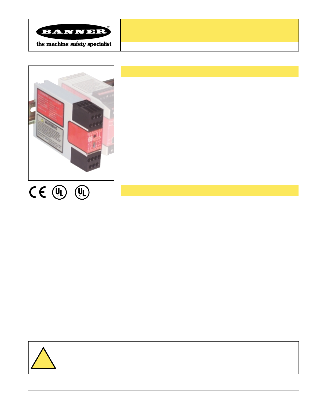
Model EM-T-7A Extension Module
One- or two-channel control for use with a Primary Safety Device
Printed in USA P/N 54208B0B
Features
• Extension Module provides additional safety outputs for a Primary Safety Device
(for example, an E-stop Safety Module or a 2-hand control module), if controlled
and monitored by this device
• Features four 6-amp switching channels for connection to control-reliable machine
power interrupt circuits
• Four redundant output channels
• Contact status outputs are provided for connection to the Primary Safety Device’s
monitoring input
• 24V dc operation
• Housed in a narrow, 22.5 mm (0.9") DIN-rail-mountable module
• Convenient plug-in terminal blocks
• Design complies with standards UL 991 and EN 60204
Description
The model EM-T-7A Extension Module provides additional forced-guided (positiveguided) relay contacts for a Primary Safety Device, such as an E-stop Safety Module or
a two-hand-control module. Controlled by the safety outputs of the Primary Safety
Device, the EM-T-7A Extension Module provides four redundant outputs. These outputs
may be connected to control-reliable machine power interrupt circuits. Each of the four
Extension Module outputs is a series connection of two forced-guided relay contacts
(K1 and K2 in Figure 3).
The outputs of the Extension Module follow the action of the safety outputs from the
Primary Safety Device which control it, within a switching delay time of approximately
20 milliseconds. The Extension Module’s four outputs are each rated for up to 250V
ac/dc at up to 6A.
The Extension Module offers an output circuit at terminals Y1 and Y2 which provides
K1 and K2 contact status information for connection to the monitoring input of the
Primary Safety Device (see Figure 3). This monitoring circuit prevents the Primary
Safety Device from being reset if contacts of either K1 or K2 of the Extension Module
fail in a shorted condition.
The Extension Module has indicators for input power (green), and status of internal
relays (K1 and K2, both green) (see Figure 1). There are no adjustments and no userserviceable parts. See page 6 for information regarding repair service.
WARNING . . .
This Extension Module is not a point-of-operation guarding device, as defined by OSHA
regulations. It is necessary to install point-of-operation guarding devices, such as safety light curtains and/or
hard guards, to protect personnel from hazardous machinery. Failure to install point-of-operation guards on
hazardous machinery could lead to serious injury or death.
R
R
C
!
Page 2

Extension Module – Model EM-T-7A
page 2
Banner Engineering Corp. • Minneapolis, U.S.A.
Website: http://www.baneng.com • Tel: 888.373.6767
IMPORTANT NOTICE . . . Read this page before proceeding!
Banner Engineering Corp. has made every effort to provide complete application, installation, operation, and maintenance
instructions. In addition, any questions regarding the use or installation of this Banner Extension Module should be directed to
the factory applications department at the telephone numbers or addresses shown on the back cover.
The user shall ensure that all machine operators, maintenance personnel, electricians, and supervisors are thoroughly familiar
with and understand all instructions regarding the installation, maintenance, and use of this Extension Module, and with the
machinery it controls.
The user and any personnel involved with the installation and use of this Extension Module must be thoroughly familiar with
all applicable ANSI/NFPA standards. The standards, listed below, directly address the use of Primary Safety Devices, by
which the Extension Module can be controlled. Banner Engineering Corp. makes no claim regarding a specific
recommendation of any organization, the accuracy or effectiveness of any information provided, or the appropriateness of
the provided information for a specific application.
The user has the responsibility to ensure that all local, state, and national laws, rules, codes, and regulations relating to the use of
this Extension Module in any particular application are satisfied. Extreme care is urged that all legal requirements have been met
and that all installation and maintenance instructions contained in this manual are followed.
U. S. Standards Applicable to Use of Primary Safety Devices
ANSI B11 Standards for Machine Tools “Safety Requirements for the Construction, Care and Use”
Available from: Safety Director
AMT – The Association for Manufacturing Technology
7901 Westpark Drive
McLean, VA 22101-4269
Tel.: 703-827-5266
NFPA 79 “Electrical Standard for Industrial Machinery (1997)”
Available from: National Fire Protection Association
1 Batterymarch Park, P.O. Box 9101
Quincy, MA 02269-9101
Tel.: 800-344-3555
ANSI/RIA R15.06 “Safety Requirements for Industrial Robots and Robot Systems”
Available from: Robotic Industries Association
900 Victors Way, P.O. Box 3724
Ann Arbor, MI 48106
Tel.: 734-994-6088
European Standards Applicable to Use of Primary Safety Devices
EN 292-1 “Safety of Machinery – Basic Concepts, General Principles for Design
Part 1: Basic Terminology, Methodology”
EN 292-2 “Safety of Machinery – Basic Concepts, General Principles for Design
Part 2: Technical Principles and Specifications”
EN 60204-1 “Electrical Equipment of Machines: Part 1: General Requirements”
Also, request a type “C” standard for your specific machinery.
EN 418 “Safety of Machinery – Emergency Stop Equipment Functional Aspects, Principles for Design”
Available from: Global Engineering Documents
15 Inverness Way East
Englewood, CO 80112-5704
Tel.: 800-854-7179
!
Page 3
Extension Module – Model EM-T-7A
page 3
Banner Engineering Corp. • Minneapolis, U.S.A.
Website: http://www.baneng.com • Tel: 888.373.6767
Supply Protection Circuitry
Application Notes There are no adjustments and no user-serviceable parts. See page 6 for information regarding repair service.
Protected against transient voltages and reverse polarity
Output Configuration Four output channels:
Each channel is a series connection of two forced-guided (positive-guided) relay contacts –
AgNi, gold-flashed
Contact ratings:
Maximum voltage: 250V ac/dc
Maximum current: 6 A ac/dc
Minimum current: 30 mA @ 24V dc
Maximum power: 1500VA, 200 W
Mechanical life: 50,000,000 operations
Electrical life: 100,000 at full resistive load
Feedback contact rating (Y1-Y2): 24V dc @ 0.5A
NOTE: Transient suppression is recommended when switching inductive loads. Install suppressors
across load. Never install suppressors across output contacts (see Warning, page 5).
Output Response Time 20 milliseconds maximum (if channel u-k fails, maximum response time is 200 milliseconds)
Status Indicators 3 green LED indicators:
Power ON
K1 energized
K2 energized
Input Requirements Inputs from Primary Safety Device must each be capable of switching 30 to 250mA @ 13 to 28V dc.
Construction Polycarbonate housing.
Mounting Mounts to standard 35 mm DIN-rail track.
Vibration Resistance 10 to 55Hz @ 0.35 mm displacement per IEC 68-2-6
Operating Temperature 0° to +50°C (+32° to 122°F)
Supply Voltage and Current A1-A2: 24V dc, +/-15%, 10% maximum ripple
Model EM-T-7A Specifications
Environmental Rating Rated NEMA 1, IEC IP20. Extension Module must be installed inside an enclosure rated NEMA 3 (IEC
IP54), or better.
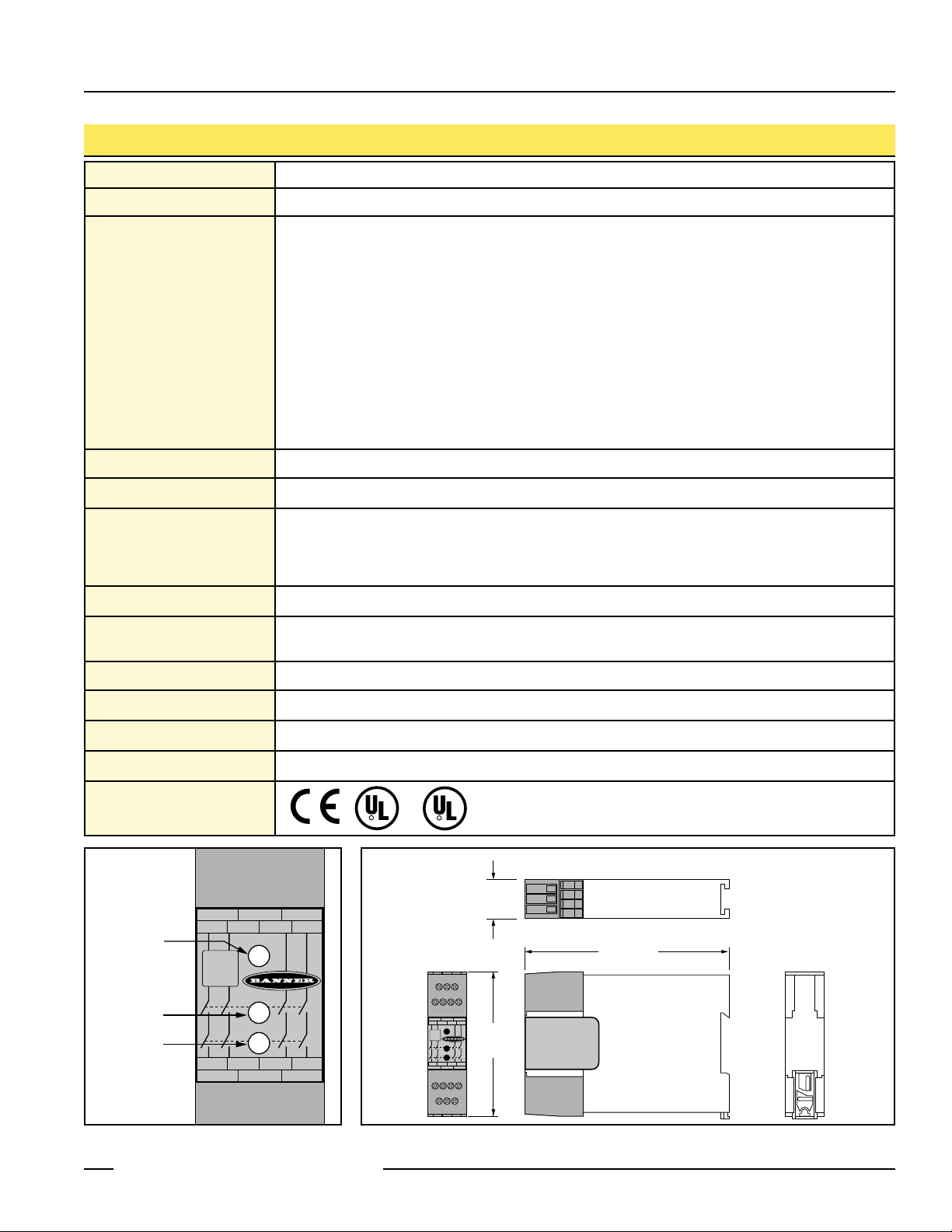
Figure 2. Extension Module enclosure dimensions
Figure 1. EM-T-7A status indicators
Certifications
R
R
C
22.5 mm
A1 Y1 K1
23 33 43
Power
Ch.1
Ch.2
UY2A2
K1
K2
(0.89")
84.0 mm
(3.31")
118.0 mm
(4.65")
Input Power
ON
K1 Energized
K2 Energized
A1 Y1 K1
13
23 33 43
Power
Machine
Safety
EM-T-7A
Ch.1
Ch.2
14 24 34 44
UY2A2
K1
K2
13
Machine
Safety
EM-T-7A
14 24 34 44
Page 4
Extension Module – Model EM-T-7A
page 4
Banner Engineering Corp. • Minneapolis, U.S.A.
Website: http://www.baneng.com • Tel: 888.373.6767
Installation
Primary Safety Device Requirements
Model EM-T-7A Extension Module is driven by one or two safety output channels of a
Primary Safety Device. The design of the Primary Safety Device must meet OSHA and
ANSI control reliability requirements. The EM-T-7A must be used ONLY with Primary
Safety Devices which have a dedicated input for feedback monitor contacts (see hookup
diagrams).
Each output channel of the Primary Safety Device must meet the following
requirements:
• Include two (or more) redundant, normally open forced-guided (positive-guided)
contacts,
• Be self-monitored to result in a safe (open) condition in the event of a contact failure,
and
• Be capable of switching 30 to 250 mA at 13 to 28V dc.
Mechanical Installation
The model EM-T-7A Extension Module must be installed inside an enclosure. It is not
designed for exposed wiring. It is the user’s responsibility to house the Extension Module in
an enclosure with NEMA 3 (IEC IP54) rating, or better.
Dimensions of the Extension Module are shown in Figure 2; it mounts directly to standard
35mm DIN rail.
Electrical Installation
As the Extension Module can be used with many different Primary Safety Devices and can
interface to a multitude of machine control configurations, it is not possible to give exact
wiring instructions for the output contacts. The following guidelines are general in nature.
The output contacts of the Extension Module have no delay function. They will open within
20 milliseconds from the time that the controlling contacts coming from the Primary
Safety Device open.
IMPORTANT: Review the following discussion of one-channel and two-channel control
before connecting the Extension Module to its Primary Safety Device.
CAUTION . . .
Dangerous Voltages
Always disconnect all power from the
Extension Module, the Primary Safety
Device, and from the machine being
controlled before making any wire
connections. Electrical installation and
wiring must be made by qualified
personnel and must comply with the NEC
(National Electrical Code), EN 60204-1
and -2, and all applicable local standards
and codes.
WARNING . . .
Not for
Use As a Stand-Alone
Safety Relay
1) DO NOT connect E-stop switches,
2-hand-control switches, safety
interlock switches, or similar devices
directly to this Extension Module.
2) ALWAYS connect terminals Y1 and Y2
of this Extension Module to the
monitoring input of the Primary
Safety Device that controls it (see
Figure 3).
This Extension Module does not have the
circuitry required to perform a self-check. A
single fault inside the unit or in external
devices like switches or E-Stop buttons
connected to the unit can go undetected
and create an unsafe condition. Failure to
properly connect this Extension Module to
a control-reliable Primary Safety Device
could result in serious injury or death.
!
Page 5

Extension Module – Model EM-T-7A
page 5
Banner Engineering Corp. • Minneapolis, U.S.A.
Website: http://www.baneng.com • Tel: 888.373.6767
WARNING . . .
Use of Arc Suppressors
If arc suppressors are used,
they MUST be installed as shown across
the actuator coil of the master stop
control elements (MSC1 to MSC4).
NEVER install suppressors directly
across the output contacts of the
Extension Module. It is possible for
suppressors to fail as a short circuit. If
installed directly across the output
contacts of the Extension Module, a
short-circuited suppressor will create an
unsafe condition which could result in
serious injury or death.
WARNING . . .
Maintain Control Reliability
NEVER wire an intermediate
device (e.g., a programmable logic
controller/ PLC), other than a safety
relay, between any safety output of the
Extension Module and the master stop
control element it switches. To do so
sacrifices the control reliability of the
control-to-machine interface, and creates
an unsafe condition which could result in
serious injury or death. Whenever a
safety relay is added as an intermediate
switching device, a normally-closed
forced-guided monitor contact of that
relay must be added to the series
feedback loop.
(Reference ANSI B11.1 – 1988,
Appendix B4)
!
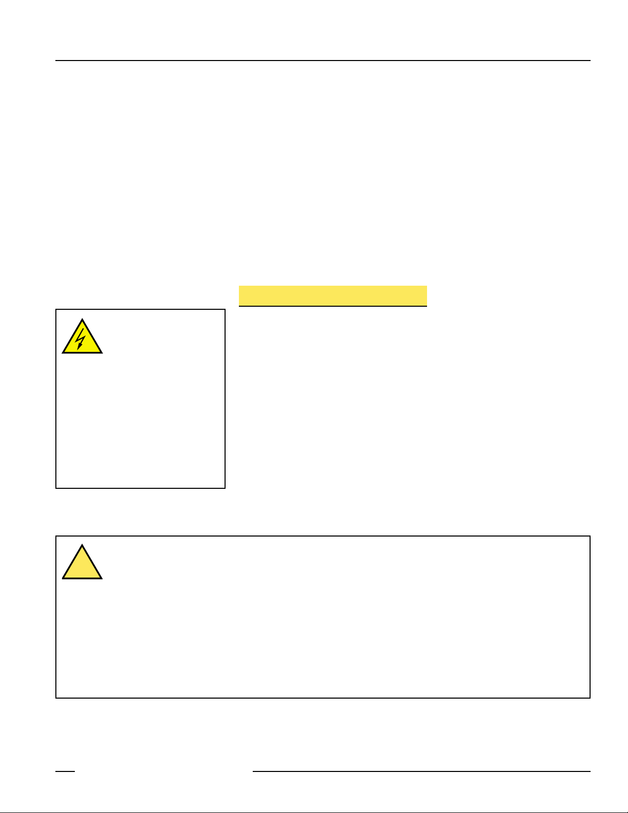
Figure 3. Generalized EM-T-7A Hookup for One-Channel Control
NOTE:
This hookup is general in
nature. Your specific hookup
may vary significantly,
depending on the Primary
Safety Device used and the
machine control configuration.
One-Channel Control (Figure 3)
One-channel control affords simplicity of wiring. However, one-channel wiring requires
eliminating the possibility of an unsafe failure of the control wires (which connect the
output of the Primary Safety Device to the input of the Extension Module). One of the
ways to reduce the probability of such failure is to locate the Primary Safety Device
adjacent to the Extension Module in the same enclosure.
The output of the Primary Safety Device must consist of two or more series-connected,
normally open contacts, coming from forced-guided safety relays. These contacts
must be monitored for failure by the Primary Safety Device. In addition, a single contact
failure cannot prevent normal stopping action, and a successive cycle cannot be
initiated until the failure has been corrected. An example of this type of output is any
single output channel of a Banner E-stop safety module.
!
L1
Machine Control Circuit
+24
V dc
EM-T-7A
A1 KY1
13
23 33 43
Monitoring Contact
Feedback Input
Primary
Safety
Device
14 24 34 44
Monitoring Contact
Feedback Input
L2
*
Machine
Master Stop
Control Elements
*Arc Suppressors
(See Warning)
MSC1
U Y2
MSC2
*
A2
0
V dc
MSC1
MSC2 MSC3 MSC4
MSC Monitor Contacts
MSC3
*
MSC4
*
Page 6

Extension Module – Model EM-T-7A
page 6
Banner Engineering Corp. • Minneapolis, U.S.A.
Website: http://www.baneng.com • Tel: 888.373.6767
Two-Channel Control (Figure 4)
Two-channel control allows the Primary Safety Device to detect an unsafe failure of the
control wires. Two-channel control should be used whenever unsafe failure of the
control wires cannot be eliminated.
The outputs of the Primary Safety Device must each be normally open, forced-guided
contacts from redundant safety relays. These contacts must be monitored for failure by
the Primary Safety Device. In addition, a single contact failure cannot prevent normal
stopping action, and a successive cycle cannot be initiated until the failure has been
corrected.
Connection to the Machine to be Controlled
The hookup diagrams in Figures 3 and 4 show a generic connection of the four safety
output channels of the Extension Module to Master Stop Control Elements MSC1
through MSC4. A Master Stop Control Element is defined as an electrically powered
device, external to the Extension Module, which stops the machinery being controlled
by immediate removal of electrical power to the machine and (when necessary) by
applying braking to dangerous motion (reference ANSI B11.19, section 5.2: “Stop
Control”). To achieve control reliability, two redundant MSCs are required to control
each machine hazard.
Figure 4. Generalized EM-T-7A Hookup for Two-Channel Control
NOTE:
This hookup is general in
nature. Your specific hookup
may vary significantly,
depending on the Primary
Safety Device used and the
machine control configuration.
NOTICE regarding MSCs
To achieve control reliability, two
redundant Master Stop Control
Elements (MSCs) are required to
control each machine hazard. Each
MSC must be capable of
immediately stopping the dangerous
machine motion, irrespective of the
state of the other. Some machines
offer only one primary control
element. For such machines, it is
necessary to duplicate the circuit of
the single MSC to add a second
MSC.
MSCs must offer at least one
forced-guided auxiliary contact
which is wired to the monitoring
contact feedback input of the
Primary Safety Device (see hookup
diagrams).
L1
Machine Control Circuit
+24
V dc
V dc
0
EM-T-7A
A1 KY1
13
23 33 43
Monitoring Contact
Feedback Input
Primary
Safety
Device
14 24 34 44
Monitoring Contact
Feedback Input
*
Machine
Master Stop
Control Elements
*Arc Suppressors
(See Warning)
U Y2 A2
MSC1
MSC2
*
MSC1
MSC2 MSC3 MSC4
MSC Monitor Contacts
MSC3
*
MSC4
*
L2
Page 7
Extension Module – Model EM-T-7A
page 7
Banner Engineering Corp. • Minneapolis, U.S.A.
Website: http://www.baneng.com • Tel: 888.373.6767
CAUTION . . .
Disconnect Power Prior to
Checkout
Before performing the initial checkout
procedure, make certain all power is
disconnected from the machine to be
controlled. Dangerous voltages may be
present along the Extension Module
wiring barriers whenever power to the
machine control elements is ON.
Exercise extreme caution whenever
machine control power is or may be
present.
To satisfy the requirements of control reliability, all MSCs must offer at least one normally
closed forced-guided monitor contact. One normally closed monitor contact from each
MSC is wired in series to the monitoring contact feedback input of the Primary Safety
Device, as shown in Figures 3 and 4. In operation, if one of the switching contacts of any
MSC fails in the shorted condition, the associated monitor contact will remain open. As a
result, it will not be possible to reset the Primary Safety Device.
Many types of mechanisms are used to arrest dangerous machine motion. Examples
include mechanical braking systems, clutch mechanisms, and combinations of brakes
and clutches. Additionally, control of the arresting scheme may be hydraulic or
pneumatic. As a result, an MSC may be one of several control types, including a wide
variety of contactors and electromechanical valves. If your machine documentation
leaves any doubt about the proper connection points for the Extension Module output
contacts, do not make any connections. Contact the machine builder for clarification
regarding connection to the MSCs.
Initial Checkout Procedure
NOTE: The Extension Module can only be used safely when its operation is controlled
via an appropriate Primary Safety Device, connected to the Extension Module
according to wiring diagrams shown in Figure 3 or 4.
Checkout procedure:
1) Remove the power controlling and switched by the machine control elements (see
Caution at left).
2) Verify that the Primary Safety Device which will be controlling the Extension
Module is operating correctly, according to its product documentation and
manufacturer’s recommendations.
3) Confirm proper connection of the Extension Module to the controlling Primary
Safety Device according to the wiring diagram (see Figures 3 and 4).
4) Verify that all four Extension Module output contacts follow exactly the operation of
the safety output contacts of the controlling Primary Safety Device, when the
Primary Safety Device is operated according to its product documentation and
manufacturer’s recommendations.
WARNING . . . MSC Monitoring
All Master Stop Control elements (MSCs), such as control relays, must be of forced-guided, captive contact design to
allow the MSC Monitoring circuit to detect unsafe failures within the master stop control elements. This monitoring
extends the safe switching point of the Primary Safety Device and the EM-T-7A Extension Module to the MSC elements. For this
monitoring to be effective, it is required that a minimum of two redundant MSCs control each hazard. This is to detect the unsafe failure
of one MSC (e.g. a welded contact), while stopping the hazard and preventing a successive machine cycle with the second MSC.
If the MSCs are the last electrically controlled device generating the hazard (i.e. not relays or contactors) and do not have forcedguided, captive contacts to monitor, then the customer must ensure that failure or fault of any single component of the MSCs will not
result in a hazardous situation and will prevent a successive machine cycle.
NOTE: MSC Monitoring is also called External Device Monitoring (EDM), MPCE Feedback, and relay backchecking.
!
Page 8

Extension Module – Model EM-T-7A
Banner Engineering Corp., 9714 Tenth Ave. No., Minneapolis, MN 55441 • Phone: 888.373.6767 • http://www.baneng.com • Email: sensors@baneng.com
WARRANTY: Banner Engineering Corp. warrants its products to be free from defects for one year. Banner Engineering Corp. will repair or
replace, free of charge, any product of its manufacture found to be defective at the time it is returned to the factory during the warranty period.
This warranty does not cover damage or liability for the improper application of Banner products. This warranty is in lieu of any other warranty
either expressed or implied.
Periodic Checkout
The checkout procedure described on page 7 should be performed according to the
intervals specified by the product documentation of the Primary Safety Device
controlling this Extension Module.
Repairs
Do not attempt any repairs to the EM-T-7A Extension Module. It contains no fieldreplaceable components. Return the Extension Module to the factory for warranty
repair or replacement.
If it ever becomes necessary to return an Extension Module to the factory, please do
the following:
1) Contact the Banner Factory Application Engineering Group at the addresses or at
the numbers listed at the bottom of page 8. They will attempt to troubleshoot the
system from your description of the problem. If they conclude that a component is
defective, they will issue an RMA (Return Merchandise Authorization) number for
your paperwork, and give you the proper shipping address.
2) Pack the Extension Module carefully. Damage which occurs in return shipping is
not covered by warranty.
 Loading...