

Page 1

Ten-Input Emergency Stop Safety Module
Model ES-TA-3F1 with DeviceNet
™
Contents
Section 1 Product Description . . . . . . 3
Section 2 Emergency Stop Switch . . . 4
Requirements . . . . . . . . . . .
Section 3 Mounting the E-Stop . . . . . 5
Safety Module
Section 4 Electrical Hookup . . . . . . . . 6
and Initial Checkout
Section 5 Operating Instructions . . . 10
Section 6 Troubleshooting . . . . . . . . 13
Section 7 Repairs . . . . . . . . . . . . . . 15
Section 8 DeviceNet . . . . . . . . . . . . 17
Section 9 Product Specifications . . . 20
Features
• Monitors up to ten normally-closed Emergency Stop switch circuits for a
contact failure or wiring fault
• Diverse-redundant input monitoring circuit
• DeviceNet
™
monitoring of status and diagnostic information
• Auto reset or monitored manual reset
•Two output switching channels for connection to control-reliable power
interrupt circuits
• Designed to comply with standards UL991, EN418, and
EN954-1 (Safety Category 4)
• For use in functional stop category 0 applications per NFPA 79
and EN418
• Plug-in terminal blocks and replaceable circuit boards
• LED indicators for status of all inputs and outputs
• Manual MAC ID Address switches and LED
• Autobaud
Buy: www.ValinOnline.com | Phone 844-385-3099 | Email: CustomerService@valin.com
R
Page 2

E-Stop Safety Module – Model ES-TA-3F1
Important ... read this page before proceeding!
Banner Engineering Corp. has made every effort to provide complete application, installation, operation, and maintenance instructions. In addition,
any questions regarding the use or installation of Banner model ES-TA-3F1 Emergency Stop Safety Module should be directed to the factory
applications department at the telephone numbers or address shown on back cover.
The user must ensure that all machine operators, maintenance personnel, electricians, and supervisors are thoroughly familiar with and understand
all instructions regarding the installation, maintenance, and use of the model ES-TA-3F1 Emergency Stop Safety Module, and with the machinery it
controls.
The user and any personnel involved with the installation and use of the model ES-TA-3F1 Emergency Stop Safety Module must be thoroughly
familiar with all applicable ANSI/NFPA standards. The standards, listed below, directly address the use of emergency stop systems. Banner
Engineering Corp. makes no claim regarding a specific recommendation of any organization, the accuracy or effectiveness of any information
provided, or the appropriateness of the provided information for a specific application.
The user has the responsibility to ensure that all local, state, and national laws, rules, codes, and regulations relating to the use of this Emergency
Stop Safety Module in any particular application are satisfied. Extreme care is urged that all legal requirements have been met and that all installation
and maintenance instructions contained in this manual are followed.
U. S. Standards Applicable to Use of Emergency Stop Safety Modules
ANSI B11 Standards for Machine Tools “Safety Requirements for the Construction, Care and Use”
Available from: Safety Director
AMT – The Association for Manufacturing Technology
7901 Westpark Drive
McLean, VA 22101-4269
Phone: 703.827.5266
NFPA79 “Electrical Standard for Industrial Machinery (1997)”
Available from: National Fire Protection Association
1 Batterymarch Park, P.O. Box 9101
Quincy, MA 02269-9101
Phone: 800.344.3555
ANSI/RIA R15.06 “Safety Requirements for Industrial Robots and Robot Systems”
Available from: Robotic Industries Association
900 Victors Way, P.O. Box 3724
Ann Arbor, MI 48106
Phone: 734.994.6088
European Standards Applicable to Use of Emergency Stop Safety Modules
EN292-1 “Safety of Machinery – Basic Concepts, General Principles for Design
Part 1: Basic Terminology, Methodology”
EN292-2 “Safety of Machinery – Basic Concepts, General Principles for Design
Part 2: Technical Principals and Specifications”
EN60204-1 “Electrical Equipment of Machines: Part 1: General Requirements”
Also, request a type “C” standard for your specific machinery.
EN418 “Safety of Machinery – Emergency Stop Equipment Functional Aspects, Principles for Design”
Available from: Global Engineering Documents
15 Inverness Way East
Englewood, CO 80112-5704
Phone: 800.854.7179
Buy: www.ValinOnline.com | Phone 844-385-3099 | Email: CustomerService@valin.com
!
Page 3

E-Stop Safety Module – Model ES-TA-3F1
SECTION 1 – Product Description
The purpose of the model ES-TA-3F1 Emergency Stop (E-stop) Safety Module is to
increase the control reliability of a multiple-input Emergency Stop circuit. The ANSI
B11.19 standard states:
“Control reliability of electrical, electronic, or pneumatic systems
frequently consists of multiple, independent parallel or series
circuitry or components so arranged that any single failure . . .
either sends a stop command to the machine tool or prevents a
successive cycle from being initiated.”
As indicated in Figure 3, a typical Emergency Stop switch offers two redundant
switching contacts. In a properly designed machine stop circuit, the opening of either of
the two Emergency Stop contacts immediately removes electrical power from the
machine control elements which react to stop hazardous machine motion and/or any
other machine hazard. This redundancy of stopping control offered by a two-pole
Emergency Stop switch is the first step towards control reliability. However, failure or
defeat of one of the switch contacts to a short-circuit will go undetected, thereby
removing the redundancy, and leaving the Emergency Stop circuit prone to eventual
failure.
The model ES-TA-3F1 E-Stop Safety Module connects up to ten Emergency Stop
switches to the machine Emergency Stop control elements. The Emergency Stop
switches become the inputs to the Safety Module, which monitors the condition of both
contacts of each E-stop switch connected to it. The output of the E-stop Safety Module
consists of two redundant output switching channels, each of which is the series
connection of two force-guided relay contacts (K1 and K2 in Figure 3).
As recommended by the Control Reliability section of ANSI B11.19, outputs of the
E-Stop Safety Module consist of two contacts (K1 and K2). These contacts are
mechanically linked, force-guided contacts, allowing the Safety Module to monitor the
outputs for failures. If the Safety Module detects failure of any contact of either the input
E-stop switches or the output relays, the Safety Module output is disabled and cannot
be reset. The two switching output circuits of the Safety Module are rated for up to
250V ac at up to 4 amps (resistive load).
The model ES-TA-3F1 E-Stop Safety Module also provides a selectable (automatic or
manual) reset function.
Key to Categories
• A Functional Stop Category (0, 1 or 2),
per EN60204-1 and NFPA79, refers to the
type of stopping action required by the
guarded machine in question. Some
machines may be stopped safely,
immediately following a stop command
(removal of power); others, due to their
high speed, mass or momentum, would
run on following an immediate stop
command. These machines require power
to be provided to the guarded machine’s
braking system for a specified delay time,
to effect a controlled stop.
Category 0 Stop: immediate removal of
power, uncontrolled stop
Category 1 Stop: controlled stop with a
delay before power is removed from
guarded machine
Category 2 Stop: controlled stop with
power left available to the guarded machine
actuators
• A Safety Category (B, 1, 2, 3 or 4), per
EN954-1, refers to “the performance of a
safety related part of a control system (or
circuit) with respect to the occurrence of
faults...” Of the many factors involved when
selecting an appropriate safety category,
hazard analysis, risk assessment and risk
reduction are among the most important.
The level of risk is based on the severity of
a potential harm and its probability of
occurring, which is used to determine the
appropriate performance of a control
system or circuit. Typically, as described in
Annex B of EN954-1, in cases where
serious injury is possible:
- Safety Category 2 would be selected
only if exposure to a hazard is
infrequent, and of a short duration.
- Safety Category 4 would be selected
if exposure to a hazard is frequent to
continuous, or if exposure is for a long
duration.
For more information, refer to standards
EN954-1, EN418, NFPA 79, EN60204-1 and
British Standard 5304:(1988).
Buy: www.ValinOnline.com | Phone 844-385-3099 | Email: CustomerService@valin.com
Page 4

E-Stop Safety Module – Model ES-TA-3F1
The Safety Module has indicators for input power, E-Stop inputs, monitor inputs, reset
input and output relay status (see Figure 1). A selector for Auto or Manual Reset is
located under the control panel cover (see page 8 for instructions). See Sections 6 and
7 for information regarding troubleshooting and repairs.
Figure 1. ES-TA-3F1 status indicators
SECTION 2 – Emergency Stop Switch Requirements
As shown in Figure 3, each Emergency Stop switch must provide two contacts which
are closed when the switches are in the “ready” position. Once activated, the
Emergency Stop switch must open both contacts. The switch may be returned to the
closed-contact position only by a deliberate action (such as twisting, pulling or
unlocking). Additionally, NFPA79, section 13.2 Emergency Stop Devices specifies the
following switch (“stop control”) requirements:
• Emergency Stop push buttons must be located at each operator control station
and at other operating stations where emergency shutdown is required.
• Stop and Emergency Stop push buttons must be continuously operable from all
control and operating stations where located.
• Actuators of Emergency Stop devices must be colored RED. The background
immediately around the device actuator must be colored YELLOW. The actuator
of a push-button-operated device must be of the palm or mushroom-head type.
• The Emergency Stop actuator must be either a momentary or self-latching type.
NOTE: Some applications may have additional requirements. The user must refer to all
relevant regulations.
WARNING. . .
Model ES-TA-3F1
Emergency Stop Safety
Module is not a point-ofoperation guarding device, as defined
by OSHA regulations. It is necessary to
install point-of-operation guarding
devices, such as safety light screens
and/or hard guards, to protect
personnel from hazardous machinery.
Failure to install point-of-operation
guards on hazardous machinery can
result in a dangerous condition which
could lead to serious injury or death.
Buy: www.ValinOnline.com | Phone 844-385-3099 | Email: CustomerService@valin.com
!
Page 5

E-Stop Safety Module – Model ES-TA-3F1
SECTION 3 – Mounting the E-Stop Safety Module
Mount the ES-TA-3F1 E-Stop Safety Module inside a lockable enclosure which has a
minimum rating of NEMA3 (IP54). The model ES-TA-3F1 E-Stop Safety Module is not
designed for exposed wiring. It is the user’s responsibility to house the Safety
Module in an enclosure with NEMA 3 (IEC IP54). For security reasons, the key to the
lockable enclosure should be in the possession of a Qualified Person (see section 5.1,
Security Protocol).
The Safety Module housing may be mounted onto standard 35 mm DIN rail or may be
mounted directly to the backplate of the lockable enclosure, using the supplied
hardware. Leave a minimum 1 cm (1/4") gap between the Safety Module housing and
adjacent housings, to allow room for potential board replacement at a later date.
The ES-TA-3F1 E-Stop Safety Module should be configured before initial checkout and
use (see section 4.4 and 4.5).
Figure 2. ES-TA-3F1 Safety Module dimensions
Buy: www.ValinOnline.com | Phone 844-385-3099 | Email: CustomerService@valin.com
7.1 mm
(0.28")
7.4 mm
(0.29")
60.8 mm
(2.40")
149.0 mm
(5.87")
134.2 mm
(5.28")
DIN Mounting Tab
(Supplied)
110.0 mm
(4.33")
35.0 mm
(1.38")
DIN Mounting Slot
Slot for Screws (2)
M3.5 x 0.6 mm (2)
75.0 mm
(2.93")
Combo Head (Phillips/Slotted) Screws
M3.5 x 0.6 mm x 14 mm (2) (#6 x 0.5" equivalent) (Supplied)
M3.5 mm Washers (2) (#6 equivalent) (Supplied)
M3.5 mm x 0.6 mm Nuts (2) (#6 equivalent) (Supplied)
Recommended torque is
16-20 in-lbs on mounting screws
Page 6

E-Stop Safety Module – Model ES-TA-3F1
Buy: www.ValinOnline.com | Phone 844-385-3099 | Email: CustomerService@valin.com
SECTION 4 – Electrical Hookup and Initial Checkout
It is not possible to give exact wiring instructions for a device such as the model
ES-TA-3F1 E-Stop Safety Module which interfaces to a multitude of machine control
configurations. The following guidelines are general in nature.
The E-Stop Safety Module has no delay function. The output relay contacts open within
25 milliseconds from the time that any Emergency Stop switch contact opens. This
classifies the E-Stop Safety Module as a functional “Category 0” Emergency Stop
control as defined by NFPA 79 (National Fire Protection Association Standard for
Industrial Machinery) and EN418 (European Standard: “Safety of Machinery,
Emergency Stop Equipment, Functional Aspects – Principles of Design”).
4.1 Connection of Emergency Stop Switches
Connect the two poles of each Emergency Stop switch as shown in Figure 3. The
switches in Figure 3 are shown in their “ready” position with both contacts closed. See
Product Specifications on page 20 for E-stop switch input requirements.
NOTE: Jumper any unused inputs to simulate an emergency stop switch in the
closed-contact position.
4.2 Connection of Reset Switch
The circuit Reset switch can be any mechanical switch, such as a normally open
momentary switch, or a two-position key switch. The Reset switch must meet the
requirements listed in the Product Specifications on page 20. The Reset switch
connects between terminals 22 and 50 of the Safety Module.
The Reset switch must be located outside and not accessible from the area of
dangerous motion, and must be positioned so that any area of dangerous motion
may be observed by the switch operator during the Reset operation. Any areas not
in full view must use supplemental guarding to detect personnel.
CAUTION . . .
Electrical Hazard
Always disconnect power
from the ES-TA-3F1 E-Stop
Safety Module and all power from the
machine being controlled before
making or removing any wire
connections.
Electrical installation and wiring must be
made by qualified personnel and must
comply with the NEC (National Electrical
Code), IEC 60204-1 and -2, and all
applicable local standards and codes.
CAUTION . . .
Do Not Use As A Safety
!
Safety Module is not to be used as a gate
or interlocking switch monitor. The use of
input devices other than emergency stop
switches (see section 2) may result in a
reduction in the safety category as
described by EN 954-1.
Switch (Interlock) Monitor
The ES-TA-3F1 E-Stop
WARNING . . .
Do Not Use Jumpers to
!
Bypass an E-stop circuit.
Page 7

E-Stop Safety Module – Model ES-TA-3F1
Figure 3. General hookup information for model ES-TA-3F1 Emergency Stop Safety Module
WARNING . . .
Arc Suppressors
If arc suppressors are used,
they MUST be installed as
shown across the load of the Master Stop
Control elements (MSC1, MSC2, MSC3
and MSC4). NEVER install suppressors
directly across the output contacts of
the E-Stop Safety Module. It is possible
for suppressors to fail as a short circuit.
If installed directly across the output
contacts of the Safety Module, a short-
circuited suppressor will create an
unsafe condition which could result in
serious injury or death.
WARNING . . .
Intermediate Devices
NEVER wire an intermediate
device (for example, a
programmable logic controller - PLC),
other than a captive contact (forceguided) relay, between E-Stop Safety
Module outputs and the Master Stop
Control element it switches. To do so
sacrifices the control reliability of the
control-to-machine interface, and
creates an unsafe condition which could
result in serious injury or death.
Whenever a force-guided relay is added as
an intermediate switching device, a
normally closed, force-guided monitor
contact of that relay must be connected in
series with the monitor contact of the
Master Stop Control element it is
switching. (Reference ANSI B11.1 – 1988,
Appendix B4)
v
Figure 4. DeviceNet connections
Buy: www.ValinOnline.com | Phone 844-385-3099 | Email: CustomerService@valin.com
Common
ES1
Emergency Stop Switch #1
ES2
Emergency Stop Switch #2
ES3
Emergency Stop Switch #3
ES4
Emergency Stop Switch #4
ES5
Emergency Stop Switch #5
ES6
Emergency Stop Switch #6
NOTE:
Use jumper wires to make connections to any
unused emergency stop switch or monitor inputs.
Wire to simulate a closed contact.
ac
b
ac
bd
ac
bd
ac
bd
ac
bd
ac
bd
L1
Machine
Control
Circuit
55
56
24V dc
29 1
2
3
ES-TA-3F1
31
30
4
5
33
32
6
7
35
34
8
9
37
36
10
11
39
38
38
12
13
41
38
40
Internal
Redundant
Safety Relays
K1 K2
14
15
43
42
16
17
45
44
18
19
47
46
20
21
49
48
22
50
23
51
24
52
25
53
26
54
27
28
+
c
a
d
bd
Emergency Stop Switch #7
abc
d
abc
d
abc
d
Reset Switch
MSC1
Monitor
MSC2
Monitor
MSC3
Monitor
MSC4
Monitor
*Arc Suppressors
(See Warning)
ES7
ES8
Emergency Stop Switch #8
ES9
Emergency Stop Switch #9
ES10
Emergency Stop Switch #10
Master Stop
Control Elements
MSC2
**
MSC1
MSC3
**
MSC4
L2
V- (black)
CAN_L (blue)
Shield
CAN_H (white)
31 32 33 34 35 36 3729 30
V+ (Red)
D5 D4 D3 D2 D1
!
!
De
Page 8

E-Stop Safety Module – Model ES-TA-3F1
4.3 Setting the MAC ID Address
In order for the DeviceNet controller to process information from its individual inputs,
each input must have a unique 2-digit address. (For example, two devices on the same
bus network may not both have 26 as their address; however, two devices within the
same factory may have addresses of 26, if they are on separate bus networks.)
The E-Stop Safety Module’s address may be assigned in two ways: locally, using the
two rotary selectors on the front of the Module (see Figure 5), or remotely, using the
rotary selectors and the DeviceNet controller. To set the address locally, set the rotary
selectors to a number between 00 and 63 and cycle power to the DeviceNet connection.
To allow the DeviceNet controller to set the address, set the rotary selectors to a
number higher than 63; the address can then be set using the controller.
The MAC ID LED will be OFF when the MAC ID address rotary switches match the
current address of the E-Stop Safety Module (as recognized by the DeviceNet
controller). If the addresses do not agree, the LED will flash. (To correct this problem,
see DeviceNet Troubleshooting.) The MAC ID LED will be ON steadily when the MAC ID
address rotary switches are above 63 and the current address of the E-Stop Safety
Module (as recognized by the DeviceNet controller) was set with the MAC ID address
rotary switches above 63.
4.4 Selecting Auto or Manual Reset Mode
The E-Stop Safety Module is switchable between Auto and Manual reset (the factory
setting is Manual). When Manual reset is selected, the E-Stop Safety Module may be
reset only by a manual Reset switch. When Auto reset is selected, the Safety Module
automatically resets whenever power is applied to the device, or at the moment when
all E-stop and Monitor inputs become closed. (The manual Reset switch is ignored
when Auto reset is selected.) Regardless of which reset method is selected, the E-stop
cannot be started unless all starting prerequisites have been met (power to the system,
and all E-stop and monitor inputs closed).
To select reset mode, open the Module cover and remove the green Reset Mode
selector from the black socket. Reinsert the Reset Mode selector so that the mode you
select (either AUTO or MANUAL, one printed on each side of the Reset Mode selector)
is facing up. (See Figure 6.)
In all cases, the user must ensure that closing the Emergency Stop switch (in Auto
reset) or manually resetting the E-Stop Safety Module does not initiate a restart (per
NFPA 79 Section 9.6.3).
Figure 6. Selecting Auto or Manual Reset
Figure 5. MAC ID address rotary selectors
and LED
Buy: www.ValinOnline.com | Phone 844-385-3099 | Email: CustomerService@valin.com
Page 9

E-Stop Safety Module – Model ES-TA-3F1
4.5 Selecting the Autobaud Feature
The model ES-TA-3F1 E-Stop Safety Module has an autobaud feature which allows for
automatic recognition of the baud rate on the network into which the Safety Module is
installed. This convenient feature automatically matches the Safety Module baud rate to
the network without requiring a baud rate configuration step. The autobaud feature is
set to ON at the factory. When the autobaud parameter is set to ON, the baud rate
parameter may not be set via the DeviceNet network. The autobaud parameter may be
turned off by setting the DeviceNet autobaud parameter to OFF (see the EDS file for
path information). When the autobaud parameter is set to OFF, the baud rate parameter
may be set via the DeviceNet network to the desired baud rate.
To determine if autobaud is set to ON, power (at the DeviceNet power inputs) the
E-Stop Safety Module while it is not connected to the DeviceNet network; the Bus
Status Indicator will flash green, then red, then OFF in a repetitive sequence. If
autobaud is set to OFF, then the Bus Status Indicator will flash green (or red) after the
initial green/red sequence at power up.
4.6 Initial Checkout Procedure
1) IMPORTANT: Ensure that there are no connections at terminals 55/27 and 56/28.
2) Close all E-stop inputs. Ensure all monitoring inputs are closed and that the Reset
input is open. (Refer to Figure 3.)
3) Apply input power to the E-Stop Safety Module at terminals 1 and 29. Verify that K1,
K2 and Reset indicators are OFF. Verify that all E-stop and monitor indicators are
ON. (If Auto/Manual Reset selector is set to Auto mode, verify that K1, K2 and all Estop indicators are ON; Reset and all monitor indicators are OFF.)
4) Close the Reset input (if Auto/Manual Reset selector is set to AUTO mode, go to
step 5). Verify that the Reset and K1 LED indicators go ON. K2 indicator should
remain OFF. Open the Reset switch and verify that the Reset indicator is OFF. The K1
and K2 indicators should both be ON at this time. If the K2 indicator comes ON
before the Reset switch is opened, disconnect the input power and check all wiring.
Return to step 2 after the cause of any problem has been corrected.
5) Activate one Emergency Stop switch (open its contacts). The K1 and K2 indicators
should turn OFF, simultaneously. If either indicator does not go OFF, check the E-stop
indicators. (The indicators for the activated Emergency Stop switch should be OFF, as
well as indicators for E-stops with higher numbers. For example, if E-stop #6 is
activated, the indicators for #6, #7, #8, #9 and #10 should all go OFF simultaneously.)
If all E-stop indicators are OK but either or both K1 and K2 indicators are ON,
disconnect the input power and check all wiring. Return to step 2 after the cause of
the problem has been corrected.
6) Repeat the above checkout procedure for each E-stop switch, individually (ES1
through ES10).
IMPORTANT . . .
Check Each Switch
Individually
Check ALL Emergency Stop
switches, individually, during each
checkout procedure. When two or more
Emergency Stop switches are used, each
switch must be individually actuated
(engaged), then re-armed and the E-Stop
Safety Module reset. This allows the
E-Stop Safety Module to check each
switch and its wiring to detect faults.
Buy: www.ValinOnline.com | Phone 844-385-3099 | Email: CustomerService@valin.com
!
Page 10

E-Stop Safety Module – Model ES-TA-3F1
4.7 Connection to the Machine to be Controlled
The hookup diagram (Figure 3) shows a generic connection of the ES-TA-3F1 E-Stop
Safety Module’s two redundant output circuits to Master Stop Control elements MSC1,
MSC2, MSC3 and MSC4. A Master Stop Control element is an electrically powered
device, external to the Safety Module, which stops the machinery being controlled by
immediate removal of electrical power to the machine and (when necessary) by
applying braking to dangerous motion (reference ANSI B11.19, section 5.2: “Stop
Control”). This stopping action must be accomplished by removing power to either
Master Stop Control element.
To satisfy the requirements of Safety Category 4 of prEN 954-1, the Master Stop
Control elements must offer a normally closed, force-guided monitor contact. One
normally closed monitor contact from each Master Stop Control element is wired to the
appropriate terminals on the module (see Figure 3). In operation, if any of the Master
Stop Control elements fails to de-energize, the associated monitor contact will remain
open. As a result, it will not be possible to reset the E-Stop Safety Module.
NOTE: If less than four MSC elements are controlled by the E-Stop Safety Module,
jumper the unused monitor inputs to simulate a closed contact. See NOTICE
Regarding MSC Monitor Hookup, at right.
Apply power to the machine control elements and perform the Periodic Checkout
Procedure (see section 5.2).
SECTION 5 – Operating Instructions
5.1 Security Protocol
The model ES-TA-3F1 E-Stop Safety Module should be mounted inside a lockable
enclosure. For security reasons, the key to the lockable enclosure must be in the
possession of a Qualified Person or Persons. A Qualified Person is a person who, by
possession of a recognized degree or certificate of professional training, or who, by
extensive knowledge, training, and experience, has successfully demonstrated the
ability to solve problems relating to the subject matter and work (ANSI B30.2-1983).
The key to the Reset switch (if the Reset switch, as installed, requires a key) should be
available to a Designated Person or Persons. A Designated Person is one who is
identified and designated in writing, by the employer, as being appropriately trained and
qualified to perform a specified checkout procedure. A machine operator who meets
these requirements may be a Designated Person.
CAUTION . . .
Dangerous Voltage
Before performing the initial
checkout procedure, make
certain all power is disconnected from
the machine to be controlled. Dangerous
voltages may be present along the E-Stop
Safety Module wiring barriers whenever
power to the machine control elements is
“ON”. Exercise extreme caution
whenever machine control power is or
may be present. Always disconnect
power to the machine control elements
before opening the enclosure housing of
the E-Stop Safety Module.
NOTICE Regarding
MSC Monitor Hookup
It is strongly recommended that one
normally closed auxiliary contact of
each Master Stop Control element
(MSC) be wired as an MSC monitor
contact, as shown in Figure 3. If this is
done, any inconsistency of action
between the MSCs will create a fault
condition, which will prevent the
E-Stop Module from resetting.
Buy: www.ValinOnline.com | Phone 844-385-3099 | Email: CustomerService@valin.com
Page 11

E-Stop Safety Module – Model ES-TA-3F1
5.2 Periodic Checkout Requirements
The functioning of the Emergency Stop system (including the E-Stop Safety Module
and the guarded machine) must be verified on a regular periodic basis to ensure proper
operation (see also the machine manufacturer’s recommendations).
Procedure:
1) With the machine running, activate one Emergency Stop switch (open its
contacts). Verify that the machine stops. (The K1 and K2 indicators should turn
OFF simultaneously. If either indicator does not go OFF, check the E-stop
indicators. The indicators for the activated Emergency Stop switch should be OFF,
as well as indicators for E-stops with higher numbers. For example, if E-stop #6 is
activated, the indicators for #6, #7, #8, #9 and #10 should all go OFF
simultaneously.) If all E-stop indicators are OK but either or both K1 and K2
indicators are ON, disconnect the input power and check all wiring. Repeat this
step after the cause of any problem has been corrected.
2) Return the Emergency Stop switch to its closed-contact position. Close and open
the Reset switch (if the controller is in Auto Reset mode, this action is not
necessary). The machine must not start at this point. Initiate the machine startup
procedure (per manufacturer’s instructions). Verify that the machine restarts in
correct sequence.
3) Repeat the above checkout procedure for each E-stop switch, individually (ES1
through ES10).
5.3 Normal Operation
Following are examples of LED status indication and DeviceNet information for typical
E-Stop Safety Module RUN, STOP, and FAULT conditions.
5.3.1 RUN Condition
The following LED status represents a normal run condition, where all E-stop switches
are closed, and the E-Stop Module has been reset so that K1 and K2 output contacts
are closed:
Figure 7. Indicator status for normal RUN condition
Operating mode: OK (Go)
E-stop Inputs: All Closed
Monitor Inputs:
Mon 1 Open
(NOTE: unused,
jumpered monitor
contacts will not be
listed as open)
Reset Mode:
Manual Reset
(or Auto Reset,
depending on selection)
Reset Input:
- - - - - (or Disabled if in Auto
Reset mode)
K1 Relay: Energized
K2 Relay: Energized
Autobaud:
On (or Off, depending
on selection)
Fault Type: No Fault
Action 1: - - - - - -
Action 2: - - - - - -
Action 3: - - - - - -
A normal RUN condition is reported to
DeviceNet as follows:
Buy: www.ValinOnline.com | Phone 844-385-3099 | Email: CustomerService@valin.com
24V
DC
PWR
+
ES1
AB
ES2
AB
ES3
AB
ES4
AB
ES5
AB
ES6
AB
ES7
AB
Indicator Key
Indicator "ON"
Indicator "OFF"
ES8
AB
ES9
AB
ES10
AB
RESET
MONITOR
123
4
K2
K1
Page 12

E-Stop Safety Module – Model ES-TA-3F1
Figure 8. Indicator status for STOP condition (E-stop switch ES3 is actuated)
Operating mode: Stop Condition
E-stop Inputs: E-Stop 3 Open
Monitor Inputs: All Closed
Reset Mode:
Manual Reset
(or Auto Reset,
depending on selection)
Reset Input:
Open (or Disabled if in
Auto Reset mode)
K1 Relay: De-energized
K2 Relay: De-energized
Autobaud:
On (or Off, depending
on selection)
Fault Type: No Fault
Action 1: - - - - - -
Action 2: - - - - - -
Action 3: - - - - - -
A STOP condition created by actuation of
E-stop switch ES3 is reported to DeviceNet
as follows:
A FAULT condition created by failure of
contact “B” of E-stop switch ES4 is
reported to DeviceNet as follows:
Operating mode: Fault Condition
E-stop Inputs: 4A Open 4B Short
Monitor Inputs: All Closed
Reset Mode:
Manual Reset
(or Auto Reset,
depending on selection)
Reset Input:
Open (or Disabled if in
Auto Reset mode)
K1 Relay: De-energized
K2 Relay: Energized
Autobaud:
On (or Off, depending
on selection)
Fault Type: E-Stop 4 Fault
Action 1: Check E-Stop 4
Action 2: New Relay Board
Action 3: New Comm. Board
Figure 9. Typical indicator status for FAULT condition (contact “B” of E-stop switch ES4
remains closed upon actuation)
5.3.2 STOP Condition
If any E-stop switch is actuated during a normal run condition, the output contacts of
K1 and K2 will open. The following LED status illustrates a situation where E-stop
switch ES3 has been actuated:
When the E-stop switch is reset, (ES3 in this example), the indicator lights for ES3,
ES4, ES5, ES6 ,ES7, ES8, ES9 and ES10 will come back ON.
K1 and K2 will close and their LED indicators will come ON:
1) After the Reset switch is closed and then opened (Manual Reset mode) or,
2) Immediately upon resetting ES3 (Auto Reset mode).
5.3.3 FAULT Condition
The following status indication illustrates a typical fault condition in which one switch
contact remains closed when an E-stop switch is actuated. This example illustrates the
situation where contact “B” of switch ES4 fails, closed:
Buy: www.ValinOnline.com | Phone 844-385-3099 | Email: CustomerService@valin.com
24V
DC
PWR
+
ES1
AB
ES2
AB
ES3
AB
ES4
AB
ES5
AB
ES6
AB
ES7
AB
ES8
AB
ES9
AB
Indicator Key
Indicator "ON"
Indicator "OFF"
ES10
AB
RESET
MONITOR
123
4
K2
K1
24V
DC
PWR
+
ES1
AB
ES2
AB
ES3
AB
ES4
AB
ES5
AB
ES6
AB
ES7
AB
ES8
AB
ES9
AB
Indicator Key
Indicator "ON"
Indicator "OFF"
ES10
AB
RESET
MONITOR
123
4
K2
K1
Page 13

E-Stop Safety Module – Model ES-TA-3F1
Fault Type Cause Recommended Action
E-stop input fault 1 input shorted, 1 input open
Check E-stop inputs
Replace Power Supply PC board
Replace Communication PC board
Replace Interconnection PC board
Reset input fault Shorted input on power up
Check Reset input
Replace Power Supply PC board
Replace Communication PC board
Monitor input
fault
Open input on power-up
or after stop
Check for open Monitor inputs
Replace Power Supply PC board
Replace Communication PC board
Output relay fault Internal circuit failure
Replace Relay PC board
Replace Communication PC board
Power fault
No power or power supply
failure
Check power, LED working?
Replace Relay PC board
Replace Communication PC board
Auto Reset fault
Missing selector card or
Internal circuit failure
Check missing Auto Reset selector card
Replace Power Supply PC board
Replace Communication PC board
The ES-TA-3F1 E-Stop Safety Module also features a self-contained provision for
troubleshooting; indicator LEDs on the front cover provide clues to possible faults. If the
circuit is working properly, the Power LED should be ON, and the individual indicator
lights for each Emergency Stop switch input should remain ON.
If one of the Emergency Stop switches connected to the circuit has been activated, its
indicator on the front panel of the module will go OFF; in addition, each indicator to the
right of it on the panel will also go OFF. (For example, if switch #4 has been activated, the
indicators for switches 4, 5, 6, 7, 8, 9 and 10 will be OFF.)
To reset, begin by verifying that the problem prompting the E-stop procedure has been
corrected. The E-stop switch indicator, and all those to the right of it on the control
module front panel, should go ON. Then activate the Reset switch connected to the
E-Stop Safety Module, and reset the E-stop switch indicated by the first LED to be OFF,
reading from left to right on the control panel. (For example, if switch #4 has been
activated, the indicators for switches 4, 5, 6, 7, 8, 9 and 10 will be OFF; start by resetting
switch #4.) Verify that all monitor indicators are ON. (If one of the monitor inputs is
open, its indicator will go OFF; in addition, each monitor indicator to the right of it will
also go OFF. For example, if monitor 2 is open, the indicators for monitor 2, 3 and 4 will
be OFF.)
If any of the E-stop switch indicators remain OFF, repeat this step with the next E-stop
switch indicator (again, the first/left-most unlit LED on the front of the module
control panel).
NOTE: After a successful reset, both of the K1/K2 indicators should be ON. If not, the E-Stop
Module has an internal fault and should be returned to the factory for repair.
SECTION 6 — Troubleshooting
Use the indicator LEDs on the E-Stop Safety Module to diagnose fault type (see Section
5.3). Use your DeviceNet Manager as a troubleshooting aid. Also, see the most current
Electronic Data Sheet (EDS) file; it assigns a number to a specific text string that will be
helpful in troubleshooting problems.
6.1 General E-Stop Module Faults
Buy: www.ValinOnline.com | Phone 844-385-3099 | Email: CustomerService@valin.com
Page 14

E-Stop Safety Module – Model ES-TA-3F1
6.2 E-Stop Module Faults Specific to DeviceNet
ES-TA-3F1
Network Status Indicator Description Recommended Action
Green ON Steady
On line, connected/allocated to
master
No action required.
Green Flashing
On line, not connected/allocated to
master;
If autobaud is ON, address and baud
rate ok
1) Connect/allocate the device to the master.
2) Check that all connectors and wiring are correct and tightly connected.
3) Check that the overall network is functional by connecting to some other
device on the same DeviceNet network.
4) If autobaud is turned OFF, set the autobaud parameter (offline) to ON or
set the MAC ID switches to a value known not to be in use and offline try
to connect at 125K (factory default), then 250K, then 500K baud until
successful. If unsuccessful, repeat step 2.
Red ON Steady
Critical network fault or
duplicate node address detected
1) Check to ensure that no other device on the network has the
same MAC ID (network address). Each DeviceNet device must have a
unique MAC ID. Use the MAC ID address switches (set at 00 to 63) or set
the MAC ID over the network by setting MAC ID parameter to the desired
value (the MAC ID switches must be set to 64 or higher to allow setting
of the MAC ID via the network.)
2) If autobaud is turned OFF, check that the configured baud rate matches
the baud rate of the network.
3) Ensure that the DeviceNet network is properly terminated and grounded
per DeviceNet specifications.
4) Check for insufficient network power supply.
Red Flashing
Connection timeout or no power to
E-Stop Safety Module
1) Check input power to the E-Stop Safety Module.
2) Check DeviceNet I/O connection time out expected packet rate (EPR)
parameter setting and/or problem with DeviceNet master.
OFF No network power or off line
1) Check the DeviceNet connector(s) for proper supply voltage and wiring
for loose or incorrect connections.
Green/Red/OFF
Autobaud detecting network baud
rate.
1) Check that all connectors and wiring are correct and tightly connected.
2) Check that the overall network is functional by connecting/allocating to
some other device on the same DeviceNet network.
3) Create repetitive network communication to some other device on the
same DeviceNet network. This will allow detection of the baud rate.
ES-TA-3F1
MAC ID Indicator Description Recommended Action
ON Steady
MAC ID address is controlled by the
master.
No action required.
Flashing
The address indicated by the MAC ID
switches does not match the current
address. This indicates that the
switch setting has been changed
with the device on. This is normal if
the user is in the process of
changing the address.
1) If switches have been changed, return the switches to the correct address
(the indicator will stop flashing).
2) If trying to change the address, complete the address change procedure.
OFF
MAC ID address is controlled by the
MAC ID switches.
No action required.
Buy: www.ValinOnline.com | Phone 844-385-3099 | Email: CustomerService@valin.com
Page 15

E-Stop Safety Module – Model ES-TA-3F1
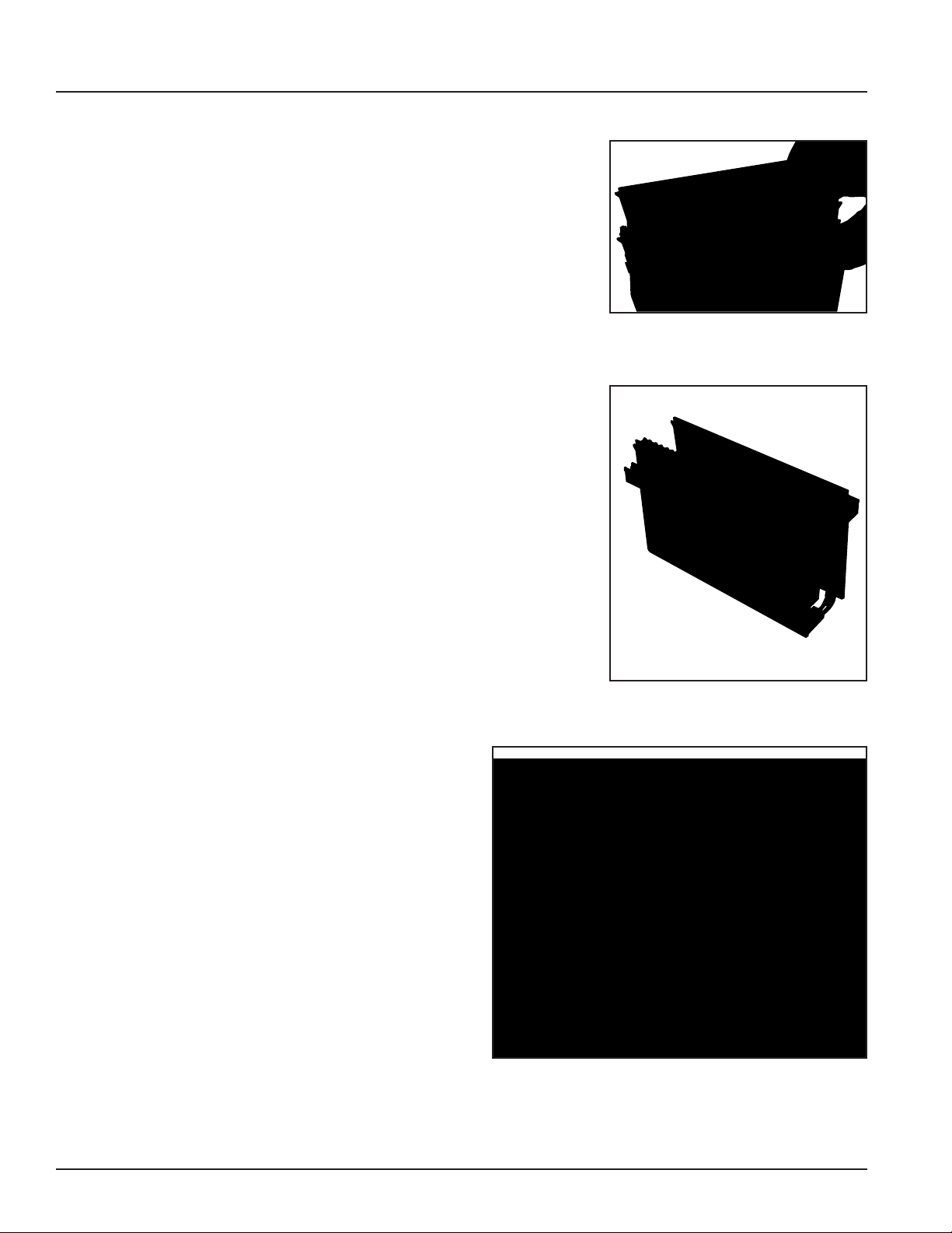
Figure 10. Gently pry up each of the five
wiring barriers.
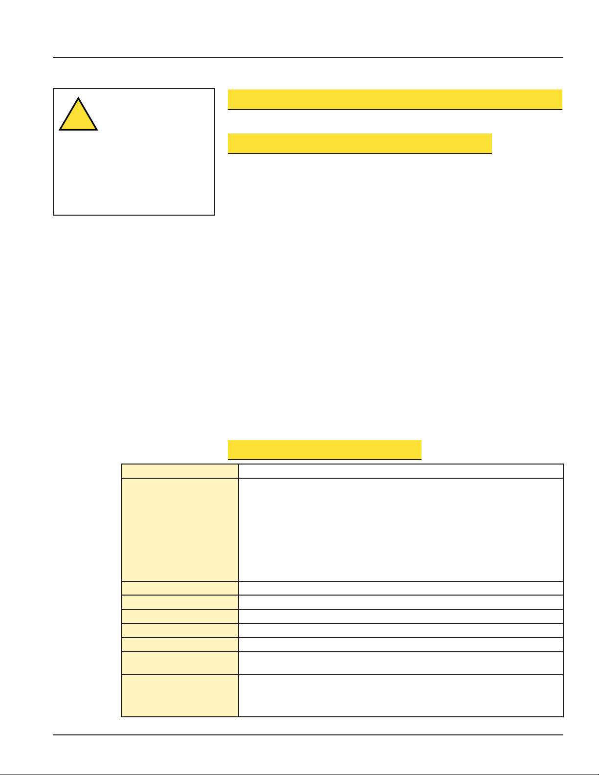
Figure 11. Remove the cover.
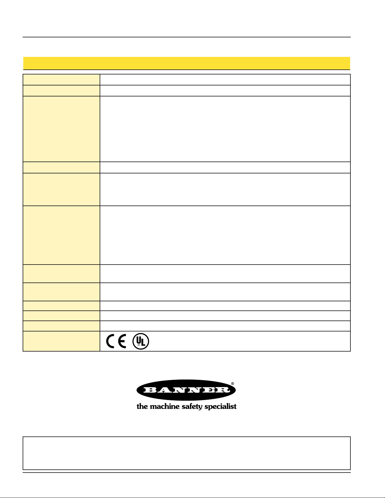
Figure 12. Gently push the sides of the
module outward.
Replacement Circuit Boards Model No. Part No.
Replacement Power Supply and Relay board ESD-PST-2 55706
Replacement Communication board with DeviceNet ESD-AB-2D 55705
Replacement Interconnection board ESD-IB-2 55704
Replacement Reset Mode Selector ESD-JB-1 54994
Removing the Circuit Boards
1) Remove the five wiring barriers (leaving the wires connected to them, if possible)
by gently prying each barrier up and off, using a flat-blade screwdriver (Figure 10).
2) Remove the cover by placing your thumb and index fingers opposite each other at
the center of the cover. Place your index (first) finger on the edge of the cover. Pull
upward on the cover center, while your index finger holds the cover edge down.
Pull until the cover edge clears the slots in the housing.
3) Gently push the sides of the module housing outward (at the top corners) to
dislodge the four locking tabs (on the two circuit boards) from the slots on the
sides of the housing (Figure 12). Pull the assembly of the three circuit boards
straight out of the module housing.
4) Disconnect the circuit boards from one another (Figure 15).
SECTION 7 – Repairs
Board Replacement
In some cases, it may be possible to repair your Module by replacing one or more of
its boards. See the chart below for the proper replacements and the installation
instructions that follow.
Buy: www.ValinOnline.com | Phone 844-385-3099 | Email: CustomerService@valin.com
Page 16
E-Stop Safety Module – Model ES-TA-3F1
Installing the Replacement Circuit Boards
1) The boards install in reverse order: first connect all three circuit boards together.
2) Align the board edges with the slots on the Module walls (use the slots which are
closest to the vented Module walls). Slide the three-board assembly into the
Module. Apply pressure on the top edge of the boards until the locking tabs on the
boards engage the slots on the housing. Squeeze the sides of the housing to fully
engage the tabs into their slots (Figure 13).
3) Replace the Module cover by holding the center of the cover between your thumb
and fingers. Place your index (first) finger on the edge of the cover. Insert the tabs
of the cover opposite your index finger into the slots on the housing. While holding
the center of the cover in an arc, insert the tabs of the other edge into the slots;
press the center of the cover into place until it is flat.
4) Remount the Module and replace the wiring barriers by pushing them down into
their receptacles. Take care to match the terminal labels on the wiring barriers with
the terminal labels on the board headers.
If it ever becomes necessary to return an E-Stop Safety Module to the factory, please
do the following:
1) Contact the Banner Factory Application Engineering Group at the address or at the
numbers listed at the bottom of the back page. They will attempt to troubleshoot
the system from your description of the problem. If they conclude that a
component is defective, they will issue an RMA (Return Merchandise
Authorization) number for your paperwork, and give you the proper shipping
address.
2) Pack the E-Stop Safety Module carefully. Damage which occurs in return shipping
is not covered by warranty.
Figure 13. Pull the three-circuit board
assembly from the housing.
Figure 14. Three-circuit board assembly.
Figure 15. Disconnect the circuit boards from one another.
Buy: www.ValinOnline.com | Phone 844-385-3099 | Email: CustomerService@valin.com
Page 17
E-Stop Safety Module – Model ES-TA-3F1
SECTION 8 – DeviceNet
8.1 Information Communicated to DeviceNet
Module Status OK (GO)
Power-Up
Stop Condition
Fault
E-Stop Inputs Status All Closed
E-Stop X Open (Where X is 1, 2, 3, 4, 5, 6, 7, 8, 9 or 10. Only
one open input is reported at a time.)
Fault (Input number and status of both circuits for that input;
i.e., 1A Open, 1B short)
Monitor Inputs Status All Closed
Monitor X Open (Where X is 1, 2, 3, or 4. Only one open
input is reported at a time.)
Reset Mode Auto Reset or Manual Reset*
Reset Input Status Open, Closed or Disabled (Reset Input is disabled in Auto
Reset mode)
Output Module Status K1 Energized or De-energized
K2 Energized or De-energized
Diagnostic Information Fault Type
Troubleshooting Suggestions
Autobaud ON* or OFF
* Factory setting
WARNING . . .
For Information
Monitoring Only
NEVER use the DeviceNet
™
data to control a safety-related function.
DeviceNet
™
information must be used for
non-safety monitoring purposes, only. To
do so creates an unsafe condition which
could lead to serious injury or death.
8.2 DeviceNet Specifications
Bus Status Indicator
A bi-colored (red/green) LED visible on the control module indicates network status:
Green Steady On line, connected/allocated to master
Flashing On line, not connected/allocated to master; if Autobaud is
ON, address and baud rate ok
Red Steady Critical network fault or duplicate node address detected
Flashing Connection timeout or no power to light screen
Green/Red OFF No network power or off line
Green/Red/OFF Flashing Autobaud detecting network baud rate
Sequentially
Power Requirements 11 to 25V dc; 80 mA (supplied by DeviceNet network)
Device Type
131 (E-Stop Safety Module)
Connection Types Supported Explicit Message, Poll, COS (Change of State)
Network Address
0-63 (Manual switches or Network configured)
Baud Rate Supported
Autobaud or Network configured (125K, 250K, 500K)
Factory setting is Autobaud ON.
EDS File Part Number
52243
EDS File Name
131_1_1.eds
Bit Map Icon File Name
131.bmp
NOTE: EDS and Bitmap files on 3.5" floppy disk supplied with
controller (part number 52243). For custom EDS files or Bitmap
files contact Banner Applications Department
Product Code
1 (10-Input E-Stop Module)
Vendor Code
12 (Banner Engineering Corp.)
Buy: www.ValinOnline.com | Phone 844-385-3099 | Email: CustomerService@valin.com
!
Page 18

E-Stop Safety Module – Model ES-TA-3F1
8.3 POLL & COS I/O Assembly Instances
Device I/O assemblies consist of:
• Poll: One product specific input assembly containing operating mode, status of E-
stop inputs, status of Monitor inputs, status of Reset Mode, status of Reset
input, status of output relays (K1 and K2), Autobaud setting and Fault type.
• COS: One product-specific input assembly containing the operating mode only.
8.4 I/O Assemblies Data Attribute Format
Assembly instance 1 is used as the response data for the Poll command. Produced
connection size of 4 bytes. Consumed connection size of 0 bytes.
Assembly instance 2 is used as the response data for the COS command. A COS
command is issued in response to a change in the E-Stop Module operating mode.
Produced connection size of 1 byte. Consumed connection size of 0 bytes.
Byte Bit 7 Bit 6 Bit 5 Bit 4 Bit 3 Bit 2 Bit 1 Bit 0
0 E-Stop Inputs Operating Mode
1
Reset
Mode
Invalid
Reset
Mode
Reset
Input
Invalid
Reset
Input
K1
Relay
Invalid
K1
Relay
State
K2
Relay
Invalid
K2
Relay
State
2 Reserved Autobaud Reserved
Monitor
Input
Invalid
Monitor
Input 4
Monitor
Input 3
Monitor
Input 2
Monitor
Input 1
3 Reserved Reserved Reserved Fault Type
Byte Bit 7 Bit 6 Bit 5 Bit 4 Bit 3 Bit 2 Bit 1 Bit 0
0 E-Stop Inputs Operating Mode
Buy: www.ValinOnline.com | Phone 844-385-3099 | Email: CustomerService@valin.com
Page 19

E-Stop Safety Module – Model ES-TA-3F1
8.5 Additional Information Available through Explicit Messaging
Autobaud Setting:
1 byte message, 0 = OFF, 1 = ON. See EDS file for path information.
Factory setting is ON.
Diagnostic Information:
See EDS file for details regarding Fault Type and Troubleshooting suggestion information.
E-Stop Inputs
0: All E-Stops are closed.
1: E-Stop 1 is open.
2: E-Stop 2 is open.
3: E-Stop 3 is open.
4: E-Stop 4 is open.
5: E-Stop 5 is open.
6: E-Stop 6 is open.
7: E-Stop 7 is open.
8: E-Stop 8 is open.
9: E-Stop 9 is open.
10: E-Stop 10 is open.
11: E-Stop 1A is open, 1B is short.
12: E-Stop 1A is short, 1B is open.
13: E-Stop 2A is open, 2B is short.
14: E-Stop 2A is short, 2B is open.
15: E-Stop 3A is open, 3B is short.
16: E-Stop 3A is short, 3B is open.
17: E-Stop 4A is open, 4B is short.
18: E-Stop 4A is short, 4B is open.
19: E-Stop 5A is open, 5B is short.
20: E-Stop 5A is short, 5B is open.
21: E-Stop 6A is open, 6B is short.
22: E-Stop 6A is short, 6B is open.
23: E-Stop 7A is open, 7B is short.
24: E-Stop 7A is short, 7B is open.
25: E-Stop 8A is open, 8B is short.
26: E-Stop 8A is short, 8B is open.
27: E-Stop 9A is open, 9B is short.
28: E-Stop 9A is short, 9B is open.
29: E-Stop 10A is open, 10B is short.
30: E-Stop 10A is short, 10B is open.
31: E-Stop status is unknown.
Operating Mode
0: Power-Up
1: OK (Go)
2: Stop Condition
3: Fault
4: Operating mode is unknown.
Reset Mode Invalid
0: The reset mode is known.
1: The reset mode is unknown.
Reset Mode
0: The reset mode is manual.
1: The reset mode is automatic.
Reset Input Invalid
0: The status of the reset input is known.
1: The status of the reset input is
unknown/disabled.
Reset Input
0: The reset input is open.
1: The reset input is closed.
K1 Relay Invalid
0: The state of the K1 relay is known.
1: The state of the K1 relay is unknown.
K1 Relay State
0: The K1 relay is OFF.
1: The K1 relay is ON.
K2 Relay Invalid
0: The state of the K2 relay is known.
1: The state of the K2 relay is unknown.
K2 Relay State
0: The K1 relay is OFF.
1: The K1 relay is ON.
Autobaud
0: Autobaud is OFF.
1: Autobaud is ON.
Monitor Input Invalid
0: The Monitor input status is known.
1: The Monitor input status is unknown.
Monitor Input 1
0: Monitor input 1 is open.
1: Monitor input 1 is closed.
Monitor Input 2
0: Monitor input 2 is open.
1: Monitor input 2 is closed.
Monitor Input 3
0: Monitor input 3 is open.
1: Monitor input 3 is closed.
Monitor Input 4
0: Monitor input 4 is open.
1: Monitor input 4 is closed.
Fault Type
0: No Fault
1: E-Stop 1 Fault
2: E-Stop 2 Fault
3: E-Stop 3 Fault
4: E-Stop 4 Fault
5: E-Stop 5 Fault
6: E-Stop 6 Fault
7: E-Stop 7 Fault
8: E-Stop 8 Fault
9: E-Stop 9 Fault
10: E-Stop 10 Fault
11: Reset Input Fault
12: Monitor 1 Fault
13: Monitor 2 Fault
14: Reserved
15: Monitor 3 Fault
16: Reserved
17: Reserved
18: Reserved
19: Monitor 4 Fault
20: Reserved
21: Reserved
22: Reserved
23: Reserved
24: Reserved
25: Reserved
26: Reserved
27: Output Fault
28: Power Fault
29: Auto Reset Fault
30: The Fault type is unknown
Buy: www.ValinOnline.com | Phone 844-385-3099 | Email: CustomerService@valin.com
Page 20
E-Stop Safety Module – Model ES-TA-3F1
Supply Protection Circuitry
Dimensions See diagram, page 10
Protected against transient voltages and reverse polarity
Output Configuration Outputs (K1 and K2): two redundant (i. e. total of four) safety relay (forced-guided) contacts
Contact ratings:
Maximum voltage: 250V ac or 250V dc
Maximum current: 4A ac or dc (resistive load)
Maximum power: 1000VA, 20 watts
Mechanical life: 10,000,000 operations
Electrical life: 100,000 at full resistive load
NOTE: Transient suppression is recommended when switching inductive loads. Install suppressors across
load. Never install suppressors across output contacts (see Warning on page 5).
Output Response Time 25 milliseconds maximum
Status Indicators 28 green LED indicators:
Power ON ES1-A ES3-A ES5-A ES7-A ES9-A Monitor-1 Reset
K1 energized ES1-B ES3-B ES5-B ES7-B ES9-B Monitor-2
K2 energized ES2-A ES4-A ES6-A ES8-A ES10-A Monitor-3
ES2-B ES4-B ES6-B ES8-B ES10-B Monitor-4
1 Bi-color red/green LED indicator for Bus Status
1 Amber LED Indicator for MAC ID
Input Requirements Emergency stop switch must have two normally closed contacts each capable of switching 20 to 150mA
@ 12 to 18V dc.
Reset switch must have one normally open contact capable of switching 20 to 150mA @ 12 to 18V dc.
Master Stop Control (MSC) Element monitor contacts must be capable of switching 20 to 250 mA @ 12 to 18V dc
Enclosure Size: See Figure 2, page 5
Material: polycarbonate. Rated NEMA 1, IEC IP20
Mounting Mounts to standard 35 mm DIN rail track. Safety Module must be installed inside an enclosure rated NEMA 3,
IEC IP54, or better.
Vibration Resistance 10 to 55Hz @ .35mm displacement per IEC 68-2-6
Operating Temperature 0° to 50°C (+32° to 122°F)
Supply Voltage and Current 24V dc ±15% at 450mA maximum; 10% maximum ripple
SECTION 9 – Product Specifications
Certifications
R
WARRANTY: Banner Engineering Corp. warrants its products to be free from defects for one year. Banner Engineering Corp. will repair or
replace, free of charge, any product of its manufacture found to be defective at the time it is returned to the factory during the warranty period.
This warranty does not cover damage or liability for the improper application of Banner products. This warranty is in lieu of any other warranty
either expressed or implied.
Buy: www.ValinOnline.com | Phone 844-385-3099 | Email: CustomerService@valin.com
 Loading...