

Page 1

BeoLink Wireless 1
Guide
Page 2
CAUTION
RISK OF ELECTRIC SHOCK
DO NOT OPEN
CAUTION: To reduce the risk of
electric shock, do not remove
cover (or back).
No User-serviceable parts inside.
Refer servicing to qualified service
personnel.
WARNING: To reduce the risk of fire or
electric shock, do not expose this appliance
to rain or moisture. Do not expose this equipment to dripping or splashing and ensure
that no objects filled with liquids, such as
vases, are placed on the equipment.
To completely disconnect this equipment
from the AC Mains, disconnect the power
supply cord plug from the AC receptacle.
The lightning flash with arrowhead symbol
within an equilateral triangle, is intended
to alert the user to the presence of un-
insulated “dangerous voltage” within the
product’s enclosure that may be of sufficient
magnitude to constitute a risk of electric
shock to persons.
The exclamation point within an equilateral
triangle is intended to alert the user to the
presence of important operating and maintenance (servicing) instructions in the
literature accompanying the product.
This class B digital apparatus meets all requirements
of the Canadian Interference-Causing Equipment
Regulations.
The internal antennas used for this mobile transmitter
must provide a separation distance of at least 20 cm
(8") from all persons, and must not be co-located or
operating in conjunction with any other antenna or
transmitter.
Modifi cations not expressly approved by this company
could void the user’s authority to operate the equipment.
NOTE: This device complies with part 15 of the FCC
Rules. Operation is subject to the following two
conditions: (1) This device may not cause harmful
interference, and (2) this device must accept any
inter ference received, including interference that may
cause undesired operation.
This equipment generates, uses and can radiate radio
frequency energy and, if not installed and used in
accordance with the instructions, may cause harmful
interference to radio communications. However,
there is no guarantee that interference will not occur
in a particular installation. If this equipment does
cause harmful interference to radio or television
reception, which can be determined by turning the
equipment off and on, the user is encouraged to try
to correct the interference by one or more of the
following measures:
– Reorient or relocate the receiving antenna.
– Increase the separation between the equipment
and receiver.
– Connect the equipment into an outlet on a circuit
different from that to which the receiver is
connected.
– Consult the retailer or an experienced radio/ TV
technician for help.
Page 3
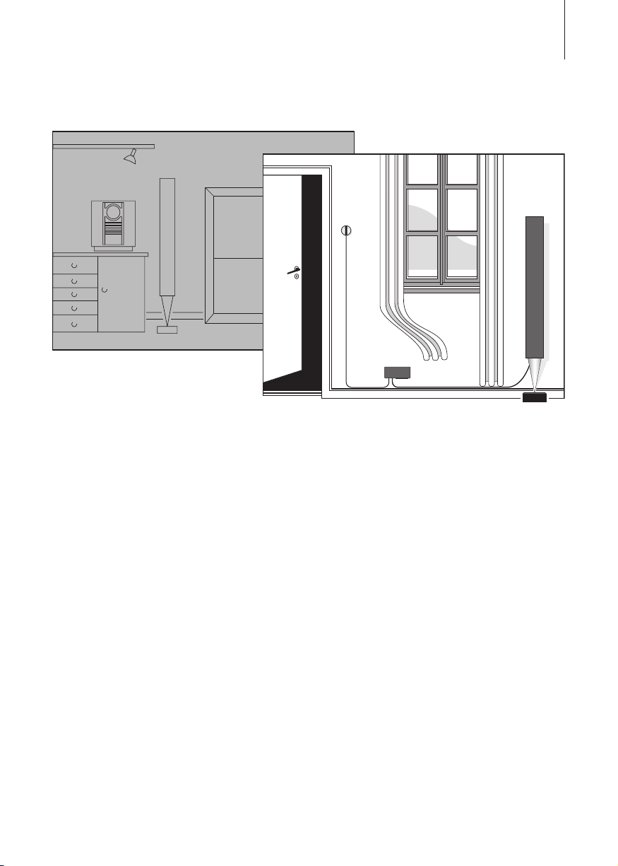
Main room
3
Link room
The main room is the room in which
you have placed the audio and/or
video system – complete with their
various sources (the main system).
Connected to the main system, you
will need a BeoLink Wireless 1 set
up as transmitter.
The link room is where you have set
up another BeoLink Wireless 1 as
receiver. To complete the link room
setup, you will need a pair of active
speakers, and an ‘IR-eye’. The ‘IReye’ is necessary in order to be able
to operate the system – either by
close-up operation, or with a Bang &
Olufsen remote control.
For information about installation
of the BeoLink Wireless 1 units and
the ‘IR-eye’, refer to ‘Set up
BeoLink Wireless 1’ (pp. 7–13) in
this Guide.
For information about how to set
up the main room system and the
link room speakers, refer to the
Guides enclosed with the products.
Page 4

4
Close-up operation
The small circular ‘IR-eye’ has
buttons for close-up operation.
You can use the buttons to
listen-in on a source currently
playing on the main system.
You can also use the buttons to
adjust the sound volume.
The but tons can also be used to
include or exclude the link
room speakers in a Timer Play
programmed on the main audio
or video system.
The Timer Play function is not avail-
able in all Bang & Olufsen systems.
Please refer to the Guide for your
main system.
Listen-in on a main room source
> Press PLAY • to listen-in on a
source that is currently playing in
your main system. If no source is
playing when you press PLAY •,
the radio in the main system will be
switched on. If the main system
have no audio sources, it will
switch on the TV program that
was last playing.
> Press PLAY • again, and the link
room speakers switch off (a red
standby indicator appears in the
PLAY • button).
If you keep the PLAY • button
pressed for more than two seconds,
both the link room and your main
system switch off.
Volume adjustment
> Press
or to raise or lower the
volume level in the loudspeakers.
The volume level in the link room
speakers is adjusted independently
of your main system.
TIMER
PLAY
Timer Play control
If the main system is programmed to
start playing auto mati cally (Timer
Play), the link room speakers can be
included as well.
> Press TIMER. A small red light in
the TIMER button indicates that
the link room speakers will be
included.
> Press TIMER again to cut out the
Timer function for the link room
(the red light disappears).
Page 5
Beo4 remote control
5
With the Beo4 remote control
you can switch on the sources
from your main audio or video
system you wish to listen to, and
you can control functions for
those sources – just as if you
were operating your main
system directly.
Functions mentioned here are only
available via BeoLink Wireless 1 if
the source in question is present in
your Bang & Olufsen system and
the source supports the function.
To switch on an Audio source …
> Press RADIO to listen to a radio
programme.
> Press CD to listen to a CD.
> Press A MEM (A TAPE) to listen
to an audio recording.
To switch on a Video source …
> Press TV to listen to TV.
> Press DTV (SAT) to listen to
digital TV.
> Press V MEM (V TAPE) to listen
to a video recording.
> Press DVD to listen to a DVD.
To switch on additional sources …
> Press LIST to display additional
sources, such as N.MUSIC (music
stored on a PC), and then press
GO to switch on a source.
Refer to the Guides supplied with
Beo4 and the audio and video
system for further information on
their operation.
TIMER
PLAY
The Beo4 remote control is avail-
able as an optional extra from a
Bang & Olufsen retailer.
Page 6

6
Beo4 – Sound adjustments
With the Beo4 remote control
you can adjust the sound coming
out of the link room speakers.
All sound levels are reset to their
original values when you switch
off the link room – unless you
store them permanently.
All the current sound levels,
including volume level, are
stored simultaneously.
The sound is adjusted
independently from the main
audio or video system.
To adjust sound volume or mute
the sound …
> Press
> Press the middle of the
To adjust speaker balance …
> Press LIST repeatedly until
> Press
or to adjust the sound
volume up or down.
button to mute the sound, and
or to restore the sound.
press
SPEAKER* is shown in the display.
or to adjust balance
left or right.
To adjust bass, treble or
loudness …
> Press LIST repeatedly until
A.SETUP* (or V.SETUP* for a
video source) is shown in the
display.
> Press GO to be able to adjust
settings.
> Press LIST repeatedly until BASS,
TREBLE or LOUDNSS is shown in
the display.
> Press
> Press GO to select the setting.
To store sound settings
permanently – making a new
preset start-up level …
> Press LIST repeatedly until
> Press GO to store settings
or to adjust the
setting.
S.STORE* is shown in the display.
permanently.
*NOTE! In order to display these
functions, you must fi rst add them
to the Beo4 list of functions. Refer
to the chapter ‘Customising your
Beo4’ in the Beo4 Guide.
Page 7

Set up BeoLink Wireless 1
7
On the next pages is explained
how to install a set of BeoLink
Wireless 1 – both in the main
room and in a link room.
We recommend that you follow
this procedure:
– Set up connection between the
Wireless 1 units as explained on
p. 8.
– Make the cable connections as
explained on pp. 9 and 11.
– Check the wireless connection
between the main room and link
room setups.
– If necessary, fasten the units to
the wall as explained on pp. 10
and 12.
– Set the link room setup to the
correct Option as explained on
p. 13.
Before you start …
– Make sure that Wireless 1 is set up
in accordance with the instructions
in this Guide. To prevent injury,
use Bang & Olufsen approved
wall brackets only!
– Wireless 1 can only be switched
off completely by disconnecting
it from the wall socket.
– Do not attempt to open Wireless 1.
Leave such operations to qualifi ed
service personnel!
– Wireless 1 is designed for indoor
use in dry, domestic environments
only, and for use within a
temperature range of 10 –40º C
(50–105º F).
– Leave enough space around
Wireless 1 for adequate ventilation.
– Do not place any items on
Wireless 1.
– Do not place the ‘IR-eye’ in direct
sunlight or direct artifi cial light (a
spotlight, for example), or near
objects generating electrical noise
(such as light dimmers), as this
may reduce the sensitivity of the
remote control receiver.
– Depending on the placement and
surroundings, Wireless 1 has an
indoor range of approximately
30 m (100').
– One transmitter can serve up to
seven receivers, and you can only
install three transmitters in a
setup.
– The transmitters must be placed
at least 5 m (16') apart.
– You will need at least one
BeoLink Wireless 1 set up as a
transmitter connected to the
main system, and one BeoLink
Wireless 1 set up as receiver in
each link room. Furthermore, you
will need an ‘IR-eye’ and a loudspeaker setup in each link room.
Page 8

8
>> Set up BeoLink Wireless 1
Wireless 1 – Transmitter/ receiver …
Wireless 1 must be set up as
either transmitter or receiver.
Before fastening the trans mitter
and receiver to the wall, you must
establish connection between
them. This must be done while
the units are located in the same
room.
The connection procedure described
here must be performed for each
receiver in a setup – one at a time.
If more than one transmitter is
necessar y, connection must be
established between each transmitter and each receiver – one by
one. Only one transmitter at a time
must be switched on, while you set
up connection to the receivers.
To set up connection between a
transmitter and a receiver …
> Set the two -position switch to
transmit or receive ( T or R),
respectively.
> Connect the transmitter and the
receiver to the mains supply.
> Press the connection button on
the transmitter and the receiver
to start a one-minute connection
mode.
> When the indicator shines green
or yellow, connection between
the transmitter and the receiver is
established. Approximately 20
seconds after connection has been
established, the receiver switches
to standby (indicator shines red).
> When the receiver switches to
standby, disconnect the units
from the mains supply, and move
them to their future positions.
If you have more receivers, repeat
the above procedure for each
receiver.
Light indications
Fast yellow fl ash … Wireless 1 is
reset to factor y setting.
Slow red fl ash … Wireless 1 is in
connection mode.
Fast red fl ash … Connection
failed/receiver out of range of the
transmitter.
Green … Connection between
the transmitter and receiver is
good.
Yel low … Connection between
the transmitter and receiver is
acceptable, but not optimal.
Red … Receiver switched to
standby.
To reset Wireless 1 to factory setting
(no connection), press and hold the
connection button until the yellow
indicator starts to flash fast.
On page 10 is shown how to get
access to the buttons and sockets.
Page 9
9
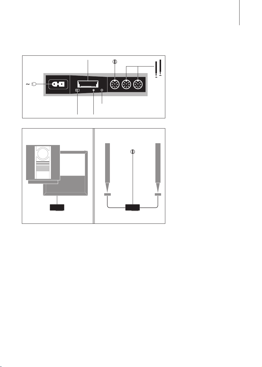
Master Link
connection
RT
Receiver/Transmitter
switch
Main room Link room
MASTER LINK
IR
Connection button
Light indicator
T
BeoLink
Wireless 1
IMPORTANT: Use fully mounted
Power Link cables only – not the
very thin t ype! If a wrong type of
Power Link cable is used, the link
room speakers will not play. If in
doubt, ask your Bang & Olufsen
retailer.
PLML PL
R
BeoLink
Wireless 1
Cable connections
In the main room: Connect the
transmitter to the Master Link
socket on the main system. Then
connect both the main system and
transmitter to the mains supply.
In the link room: Connect the
loud speakers to the Power Link
sockets on the receiver. Connect
the ‘IR-eye’ to the socket marked
IR (for information about the ‘IReye’ and its cable, see p. 11). Then
connect both the loud speakers and
the receiver to the mains supply.
Check the indicator light in the
receiver to ensure that connection
is still intact. If the connection is
lost, the units must be moved. The
receiver switches to standby after
approximately 20 seconds.
Page 10

10
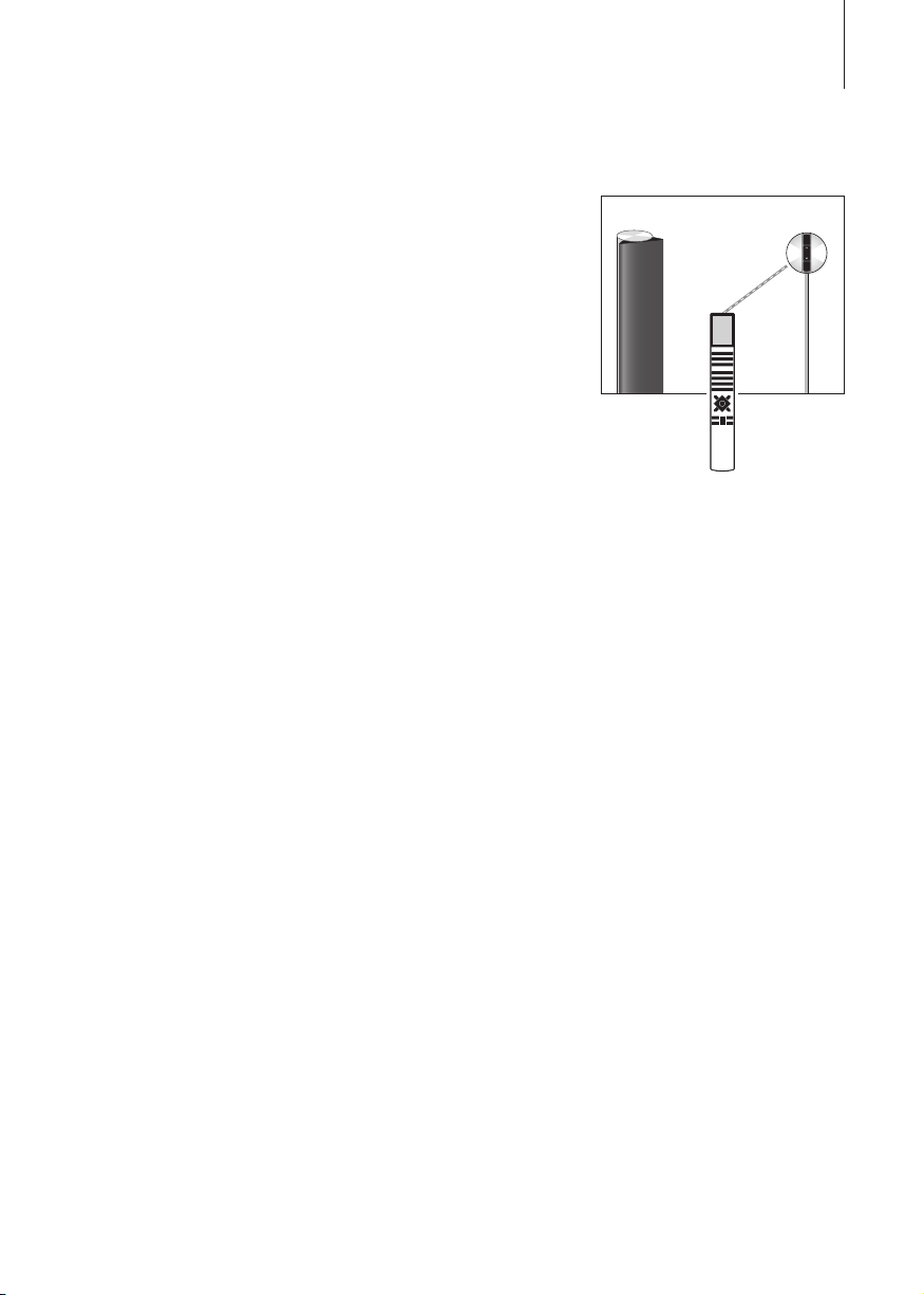
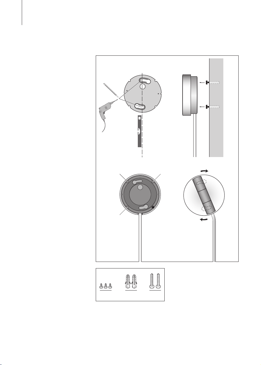
Wireless 1 – wall mount
Wireless 1 can be fastened to a
wall (or ceiling) with one of the
two enclosed brackets – in either a
horisontal or a vertical position. It
can be placed on the bracket so that
the cables may be run either to the
left or to the right. However, if you
place Wireless 1 vertically on a wall,
the cables must be run down wards
– otherwise the bracket will not hold
Wireless 1 safely!
Use two screws and wall anchors,
each with a minimum load rating
of 1.6 kg (3.5 lbs.). However, if you
intend to hang Wireless 1 from a
gypsum wall or ceiling, one screw
must be a lag screw (4 mm – 0.15"),
which penetrates the gypsum, and
is screwed a minimum of 12 mm
(0.5") into a vertical stud. The other
screw must be of a type intended
for gypsum panels.
>> Set up BeoLink Wireless 1
To get access to the connection
button and sockets, you must first
remove the cover. When you have
connected the cables and checked
that the wireless connection is still
intact, run the cables through the
groove and put on the cover again.
When you have put on the cover,
slide Wireless 1 onto the bracket as
shown.
Page 11

1
2
3
4
5
A
Connect the leads in the cable to the
terminals inside the receiver in this
order:
1 = Yellow
2 = Grey
3 = Green
4 = White
5 = Brown
35 mm – 1.5"
5 mm – 0.25"
Strip the cable end. Twist the cores
in each lead and bend them back.
11
‘IR- eye’ – cable connections
The small circular ‘IR-eye’ is
available from a Bang & Olufsen
retailer. An ‘IR-eye’ must be used
in each link room setup. Use the
cable supplied with the ‘IR-eye’
and connect it as explained here:
> Cut the cable to the required
length (from the receiver to the
‘IR-eye’) and strip it as shown.
> Insert the cable end through the
cable clamp (A) and connect the
leads to the terminals inside the
‘IR-eye’ in the order indicated.
Then tighten the clamp (A).
> Attach the rear cover and fi x the
‘IR-eye’ to the wall as explained on
the next page – and then plug the
cable into the socket marked IR
on the receiver.
Page 12
C
C
12
‘IR-eye’ – wall mount
If the ‘IR-eye’ is placed next to a
door and at a suitable height, you
can easily switch on or off by closeup operation when entering or
leaving the room. Likewise, if it is
placed near your telephone, you
can switch off the speakers while
you are on the phone.
> Use the wall plate as a template
to mark up the holes on the wall.
Insert the screws and wall
anchors, but let the two screw
heads protrude from the wall as
shown (C/D ).
> Place the wall plate onto the rear
of the ‘IR-eye’, and fasten it with
the three screws (B).
> Insert the two protruding screw
heads (D) into the corresponding
‘keyholes’, and turn the ‘IR-eye’
clockwise to fasten it.
>> Set up BeoLink Wireless 1
D
D
BB
B
BCD
Page 13
Ready for use …
13
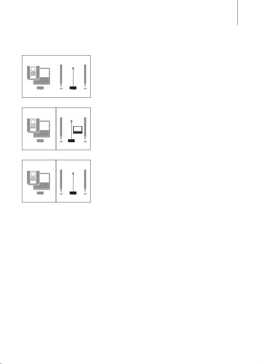
Option 4
RT
Option 5
RT
Option 6
RT
Option settings
When you have made all the
connections as described on the
previous pages, you may start to
use the system. However, in order
for your setup to function properly,
you must set the link room setup
to one of the following Options:
Option 0: Used if you want to
disable remote con trol operation
in the link room.
Option 4: Used if you install a link
room setup in the same room as
your main system (for example in
a large L-shaped room with two
separate listen ing positions).
Option 5: Used if you set up a
Bang & Olufsen television in the
link room.
Option 6: Used in a setup with the
main system in one room, and
the link room setup in another –
as described in this guide (this is
the factory setting).
Use a Beo4 remote control to set
the Option. The entire system must
be switched to standby.
> While holding down the • button,
press LIST.
> Let go of both buttons.
> Press LIST repeatedly until
OPTION? is shown in the Beo4
display, and press GO.
> Press LIST repeatedly until L.OPT
is shown in the Beo4 display,
and then key in the appropriate
number (0, 4, 5 or 6).
Wireless interference
Signals between the transmitter
and receiver can be infl uenced by
other systems, such as microwaves
or wireless pc systems, as well as
wireless telephone systems in the
USA. If interferences occur, you
should try to correct it by one or
more of the following measures:
– Reorient or relocate the receiver
to improve reception.
– Increase separation bet ween the
disturbing equipment and the
receiver.
– Consult your Bang & Olufsen
retailer for assistance.
Page 14

14
Waste Electrical and Electronic
Equipment (WEEE) –
Environmental protection
The European Parliament and the
Council of the European Union
have issued the Waste Electrical
and Electronic Equip ment Directive.
The purpose of the Directive is the
prevention of waste of electrical
and electronic equipment, and to
promote the reuse and recycling
and other forms of recovery of
such waste. As such the Directive
concerns producers, distributors
and consumers.
The WEEE directive requires that
both manufacturers and endconsumers dispose of electrical
and electronic equipment and
parts in an environmentally safe
manner, and that equipment and
waste are reused or recovered for
their materials or energy.
Electrical and electronic equipment
and parts must not be disposed of
with ordinary household refuse; all
electrical and electronic equipment
and parts must be collected and
disposed of separately.
Products and equipment which
must be collected for reuse,
recycling and other forms of
recovery are marked with the
pictogram shown.
When disposing of electrical and
electronic equipment by use of the
collection systems available in your
country, you protect the
environment, human health and
contribute to the prudent and
rational use of natural resources.
Collecting electrical and electronic
equipment and waste prevents the
potential contamination of nature
with the hazardous substances
which may be present in electrical
and electronic products and
equipment.
Your Bang & Olufsen retailer will
assist with and advise you of the
correct way of disposal in your
country.
Page 15

This product fulfils the conditions
stated in the EEU directives 89/336,
73/23 and the safety standard
EN60065, 2002 – CE 2005.
This product may be used in member
states of the EEU and EFTA.
Technical specifications, features
and the use thereof are subject to
change without notice!
Page 16

www.bang-olufsen.com
3507757 0601 Printed in Denmark by Bogtrykkergaarden a-s
 Loading...