

Bang & Olufsen BeoVision 12-65 MK II, BeoVision 12-65, BeoSystem 4, 9666, 9670 Installation Manual
...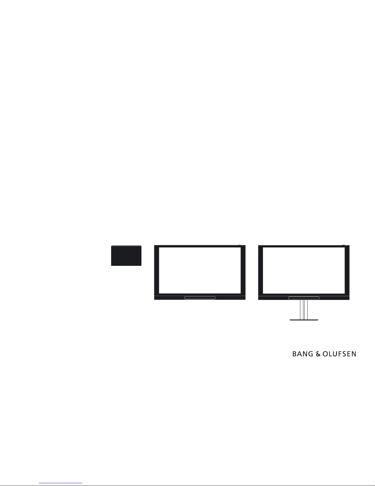
BeoSystem 4
Type 9666 - 9670
BeoVision 12-65
Type 7953 - 7957
BeoVision 12-65 MK II
Type 7958, 7964, 7967, 7977 - 7978
Installation Guide
English - version 1.3
8.6
28.043.9
161.0
96.3
5.8
2014- 06 -17T08:0 5 v1-3- 01
in Design
Introduction 2
Introduction
The BeoSystem 4 is a highly advanced unit for controlling either at screen monitors, such as BeoVision 12-65, or a projector. BeoSystem 4
connects to almost any source, plays most formats, controls surround sound and speakers in more rooms and can be operated e.g. by the Beo4
remote control.
This installation guide will show you how to handle the BeoSystem 4 and the BeoVision 12-65 regarding installation. Also guiding for installation
of projectors is included.
Additional information may be found via BeoWise > Software & Tools > BeoLiving Tools, then choose Projector adjustment guides and
choose the appropriate product and Addition to adjustment guide; Samsung SP-A900B and SIM2 projectors to BeoSystem 4.
See also BeoLink Handbook regarding cables and wiring of the IR-eye etc. via BeoWise and choose General documents followed by choosing
BeoLink Handbook.
BeoSystem 4 dual screen setup is found in a separate installation guide via BeoWise > Video > BeoSystem > BeoSystem 4.
How to navigate this guide
When the guide is opened, it automatically opens in Full Screen Mode (can be kept or changed - see Esc below). This is primarily done to optimise
the usability of screen reading. There are several ways to navigate when using the guide, see the survey of keys, shortcuts and hot keys below:
/ (arrow keys on the keyboard) navigates to the next page
/ (arrow keys on the keyboard) navigates to the previous page
Esc
(Esc button ) exits Full Screen Mode (press Ctrl + L to return to Full Screen Mode).
Another feature to optimise the navigation is the navigation icons in the bottom of the screen (see below for explanation).
Navigates you to the previous view
Navigates you directly to the start page
Navigates directly to the table of contents (these are active links - click the link to be directed directly to the associated section)
Prints the document - the print dialogue box opens (Ctrl + P also brings up this feature)
Furthermore, to ease the navigation, this guide contains links. The links are mouseover active and marked with blue text. Just click on a page
reference to be transferred to that page.

How to use this installation guide 3
How to use this installation guide
This installation guide gives step by step instructions in how to install:
- BeoSystem 4 connection panels
- Placement and mains cable connection
- Installation scenarios
- Extending cables
- Screen measurement
- Shortening IR-blaster cables
- General about Projector Screen
- Speaker placement
- Customer Service Menu
- Connecting external sources
- Scene setup using Open Collector
- Video Output formats
- Video Input formats
- Outer dimensions
- Cables
- Cable information
- Wring diagram - external cables
- Connection specications
Navigation TIP
The right side of this page and the Table of Contents, page 81, acts
as an active table of contents. Simply click the subject you want and
you are transferred to the section in question.
Introduction
Install BeoSystem 4 with 3rd party TV displays
Placement
Speaker placement
Scene setup - Open Collector setup
Shortening IR blaster cables - PUC cables
Projector Screen - general information
Cables
Video Input formats
How to use this installation guide
Extending cables
Connecting mains cable
Screen measurement
Install BeoSystem 4 with BeoVision 12-65
Customer Service Menu
Video Output formats HDMI OUT
Connection specications
Projector placement
Connecting external sources
Cable information
Wiring diagram - external cables
Outer Dimensions
Contents
BeoSystem 4 connection panel
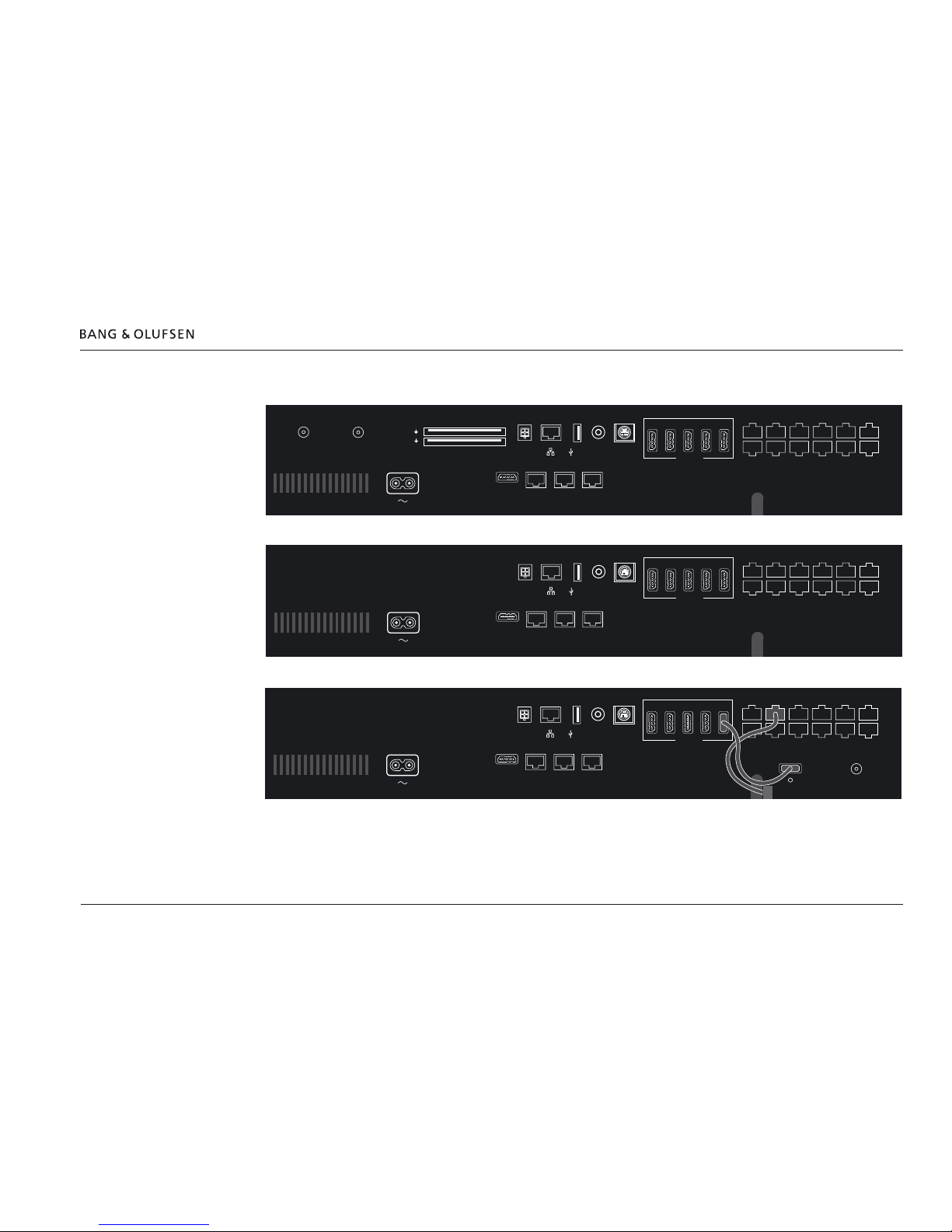
BeoSystem 4 connection panel 4
BeoSystem 4 connection panel
EU connection panel
US connection panel
Korea connection panel
CTRL 1 CTRL 2 CTRL 3
PUC 3 A+B PL 1 PL 2 PL 3
EXT IR PUC 1
A+B
CTRL 4
PUC 2
A+B
CTRL 5
NOT
USED
PL 4
PL 5
1 2 3 45
HDMI IN
AV
IN
S/P-DIF
IN
5V
0,5A
12V=1.0A
STAND
COMMON INTERFACE
CHIPSIDE
CHIPSIDE
5V=50mA
AERIAL
14/18V=0.4A
SATELLITE
HDMI
OUT
MONITOR
CONTROL
IR/AUTO
CONTRAST
PL 6
CTRL 1 CTRL 2 CTRL 3
PUC 3 A+B PL 1 PL 2 PL 3
EXT IR PUC 1
A+B
CTRL 4
PUC 2
A+B
CTRL 5
NOT
USED
PL 4
PL 5
1 2 3 45
HDMI IN
AV
IN
S/P-DIF
IN
5V
0,5A
12V=1.0A
STAND
HDMI
OUT
MONITOR
CONTROL
IR/AUTO
CONTRAST
PL 6
CTRL 1 CTRL 2 CTRL 3
PUC 3 A+B PL 1 PL 2 PL 3
EXT IR PUC 1
A+B
CTRL 4
PUC 2
A+B
CTRL 5
NOT
USED
PL 4
PL 5
1 2 3 45
HDMI IN
AV
IN
S/P-DIF
IN
5V
0,5A
12V=1.0A
STAND
HDMI
OUT
MONITOR
CONTROL
IR/AUTO
CONTRAST
PL 6
AERIAL
Placement - Wall mounting 5
Placement
The BeoSystem 4 can be mounted in various ways:
- On a shelf or similar horizontal surface, e.g. in a cabinet
- Wall mounted
- Rack mounted
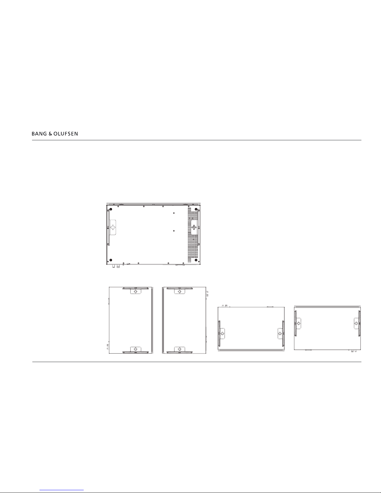
Wall mounting
- BeoSystem 4 can be mounted on a wall by adding the wall brackets, each using the existing screws.
See also the installation guide enclosed in the packaging for the brackets.
The BeoSystem 4 can by placed upright (with the cables directed to the left or right) or horizontally (with the cables directed up or down).
See example in the below illustrations. (The brackets shown are placed on the back side of the BeoSystem 4).

6
Rack mounting
The BeoSystem 4 can be mounted in a 19” rack by adding the brackets for rack mounting. The BeoSystem 4 can be placed with the cables to the
front or hidden at the back side of the BeoSystem 4. See example in the below illustration. The brackets for rack mounting can be placed ush
with the cabinet front/rear or displaced in order to have the cables in front of the BeoSystem 4 although behind the cabinet front frame. Examples
are shown below.
See also the installation guide enclosed in the packaging for the brackets.
Temperature control
It is recommended to place a fan to force the air-circulation when the BeoSystem 4 is mounted in a rack system or cabinet. This is to keep the
ambient temperature below 40 ˚C.
Placement - Rack mounting 6
Connecting mains cable 7
Connecting mains cable
Connect the mains cable plug into the mains socket of the BeoSystem 4 and mount the cable holder as shown.
Install BeoSystem 4 with BeoVision 12-65 8
Install BeoSystem 4 with BeoVision 12-65
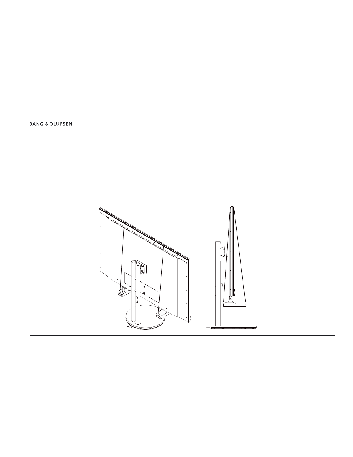
Lifting equipment
The weight of the BeoVision 12-65 MK II is 81.4 kg / 179.2 lbs.
Due to the heavy weight of the product, any moving or lifting of the product should be performed by qualied personnel – using the proper
equipment.
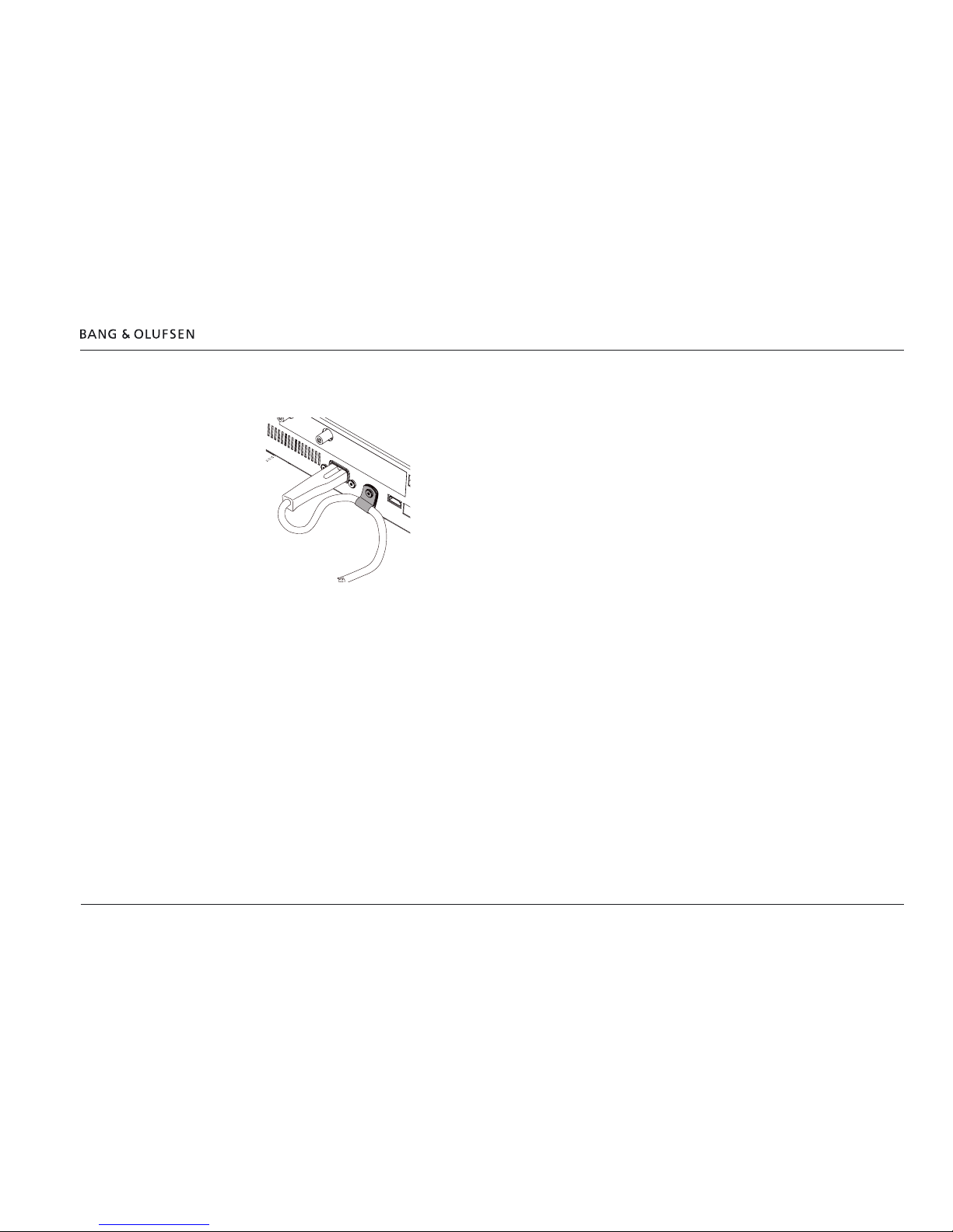
Unpacking and handling service stand
When unpacking the BeoVision 12-65, mount the service stands (Bang & Olufsen part No.: 3376433, 1 pcs.) and secure their position by applying
a rubber band with hooks per service stand as illustrated. The BeoVision 12-65 can then be moved from the packaging and placed as desired until
placed properly on the stand.
The rubber bands with hooks are included with the Calibration kit BeoSystem 4; other parts of the calibration kit is used for screen measurements,
see part number page 20.
Install BeoSystem 4 with BeoVision 12-65 9
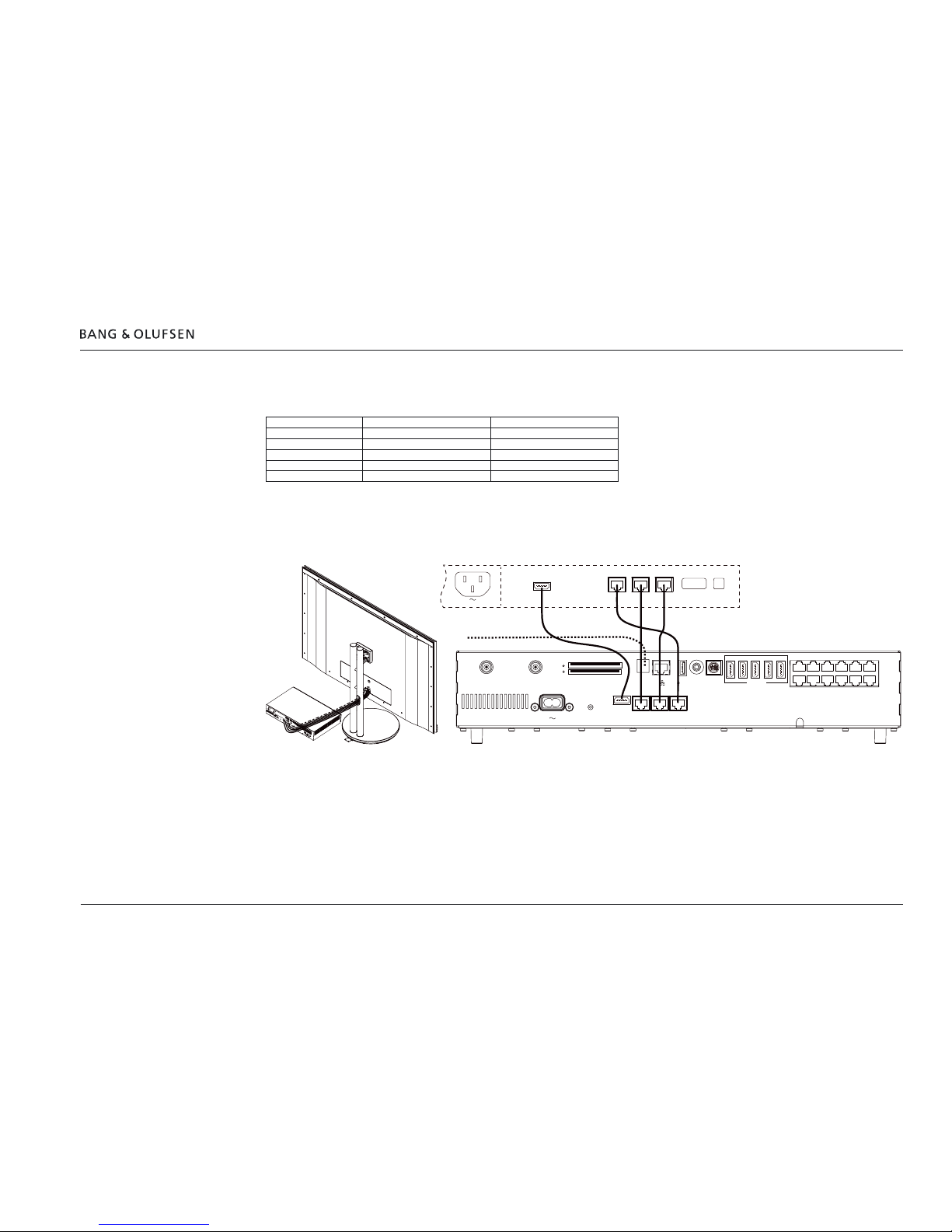
Cabling
The cabling between the BeoSystem 4 the BeoVision 12-65 consists of:
Cable type Socket on BeoSystem 4 Socket on BeoVision 12-65
HDMI HDMI OUT HDMI IN
Cat 7 CONTROL MONITOR CONTROL
Cat 7 IR/AUTO CONTRAST IR OUT
Cat 7 PL6 POWER LINK
CAN bus cable 12V = 1.0A STAND -
Let the CAN bus cable run into the connection panel of the BeoVision 12-65 and run this cable in the Cable Manager together with the other
cables to the BeoSystem 4.
Extending cables, see page 11.
HDMI
IN
POWER
LINK
CONTROL IR Out
ACM
IR IN
CTRL 1 CTRL 2 CTRL 3
PUC 3 A+B PL 1PL 2PL 3
EXT IR PUC 1
A+B
CTRL 4
PUC 2
A+B
CTRL 5
NOT
USED
PL 4
PL 5
12345
HDMI IN
S/P-DIF
IN
5V
0,5A
12V=1.0A
STAND
COMMON INTERFACE
CHIPSIDE
CHIPSIDE
5V=50mA
AERIAL
14/18V=0.4A
SATELLITE
HDMI
OUT
MONITOR
CONTROL
IR/AUTO
CONTRAST
PL 6
AV
IN
CAN cable
for Stand
Connection panel for
BeoVision 12-65
Install BeoSystem 4 with 3rd party TV display 10
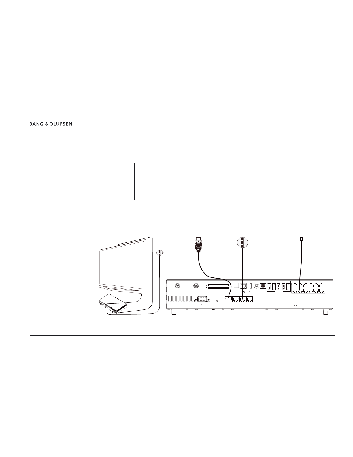
Install BeoSystem 4 with 3rd party T V display
Cabling
The cabling between the BeoSystem 4 and a 3rd party television consists of:
Cable type Socket on BeoSystem 4 Socket on 3rd party TV
HDMI HDMI OUT HDMI IN
IR blaster (6271234) e.g. PUC 1 [to be placed in front of the
IR receiver of the TV]
IR cable BLC NL/ML, RJ45
to pigtail, 10 m / 33 ft,
White (6271239)
Connect an IR-eye without
autocontrast (8087030) to the
IR/AUTO CONTRAST socket
Cat 7 (6271026, 6271027,
6271028)
Connect an IR-eye without
autocontrast (8087030) to the
IR/AUTO CONTRAST socket
-
Note: The IR-eye used is the type without autocontrast (Part No.: 8087030), and a Network Link Product Cable (e.g. of appropriate length for
example: 10 m / 33 ft, Part No.: 6271027; 20 m / 66 ft, Part No.: 6271028) is mounted. Alternatively the IR cable RJ45, 10 m / 33 ft, Grey (Part.
No.: 6271239) may be used. See BeoLink Handbook via BeoWise for information on connection of wires.
Extending cables, see page 11.
CTRL 1 CTRL 2 CTRL 3
PUC 3 A+BPL 1PL 2 PL 3
EXT IR PUC 1
A+B
CTRL 4
PUC 2
A+B
CTRL 5
NOT
USED
PL 4
PL 5
12345
HDMI IN
S/P-DIF
IN
5V
0,5A
12V=1.0A
STAND
COMMON INTERFACE
CHIPSIDE
CHIPSIDE
5V=50mA
AERIAL
14/18V=0.4A
SATELLITE
HDMI
OUT
MONITOR
CONTROL
IR/AUTO
CONTRAST
PL 6
AV
IN
Extending cables 11
Extending cables
Cat 7 cables
Cat 7 cables should never be extended. They must be run in the appropriate length from product to product, from wall outlet to distribution frame
or from product to wall outlet.
HDMI cables
HDMI cables may be used up to 10 m / 33 ft. When longer HDMI cables are needed they must be of the active type or an HDMI extender may be
used (e.g. the recommended solution from Atlona; see page 14 and page 16.
CAN bus cable for Floor Stand
The CAN bus cable for the oor stand with BeoVision 12-65 is 9.8 m / 32.2 ft long. If the cable between the BeoVision 12-65 and the BeoSystem
4 is longer, the CAN bus cable can be cut at an appropriate place, and extended by applying Network Link Product Cable; see page 61, (Cat 7
cable). The cables are assembled by two Power Link Junction Boxes (Bang & Olufsen Part No. 3132055).
The cabling is explained and illustrated in the following two scenarios:
- Hidden installation via wall outlet to the BeoSystem 4 placed in the Technical Room or similar cabinet, see page 12. The cables are connected
using the Power Link Junction Boxes.
- Visible installation using Cat 7. Cables are connected using the Power Link Junction Boxes, and run directly to the BeoSystem 4, see page 13.
Note: The maximum length of the Cat 7 cable, used to extend the 9.8 m/32.2 ft CAN bus cable, is 50 m/164 ft .
Note: To ensure correct quality of the signal and as little signal loss as possible, two wires of the Cat 7 cable is used per wire in the CAN cable; see
example page 11.
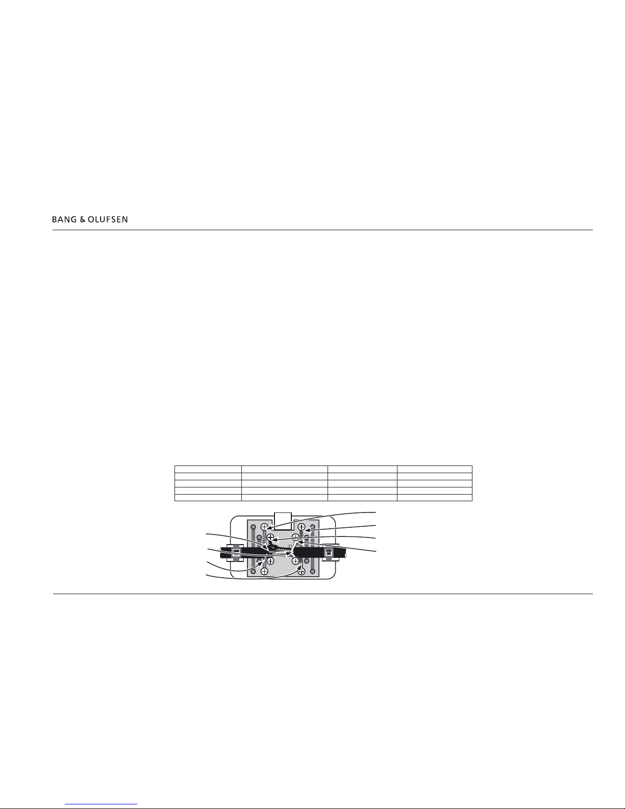
Wire connection
Ensure to match the same colours in both Power Link Junction Boxes; see illustrations below.
CAN plug pin numbers Function CAN bus cable colour Cat 7 cable colour
1 CANL Negative CAN bus signal Black Blue + White/Blue
2 GND_STAND ground for stand White Green + White/Green
3 CANH Positive CAN bus signal Orange Orange+ White/Orange
4 12V_STAND_C 12V for stand TMDS Red Brown + White/Brown
Black
White
Orange
Red
Orange + White/Orange
Brown + White/Brown
Blue + White/Blue
Green + White/Green
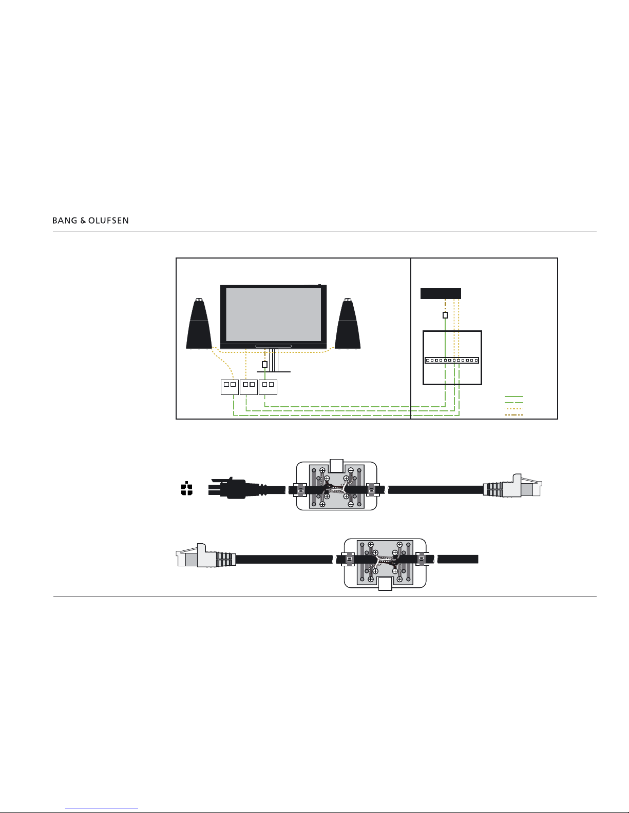
Extending cables 12
Cabling via wall outlets - hidden
The cabling can run via wall outlets and is cross connected in the distribution frame in the technical room or alternative place following the
principles as illustrated; see simplied illustration above. Cable connections in the Power Link Junction Box is shown below.
2xRJ45 2xRJ45
BeoSystem 4
2xRJ452xRJ45
Living room Technical room
Network Link
Cat 7
Power Link
CAN
Cabinet /
distribution frame
12
34
CAN cable to
BeoSystem 4
Connection in
distribution frame
Connection to
wall outlet
Cable from
BeoVision 12-65
Stand
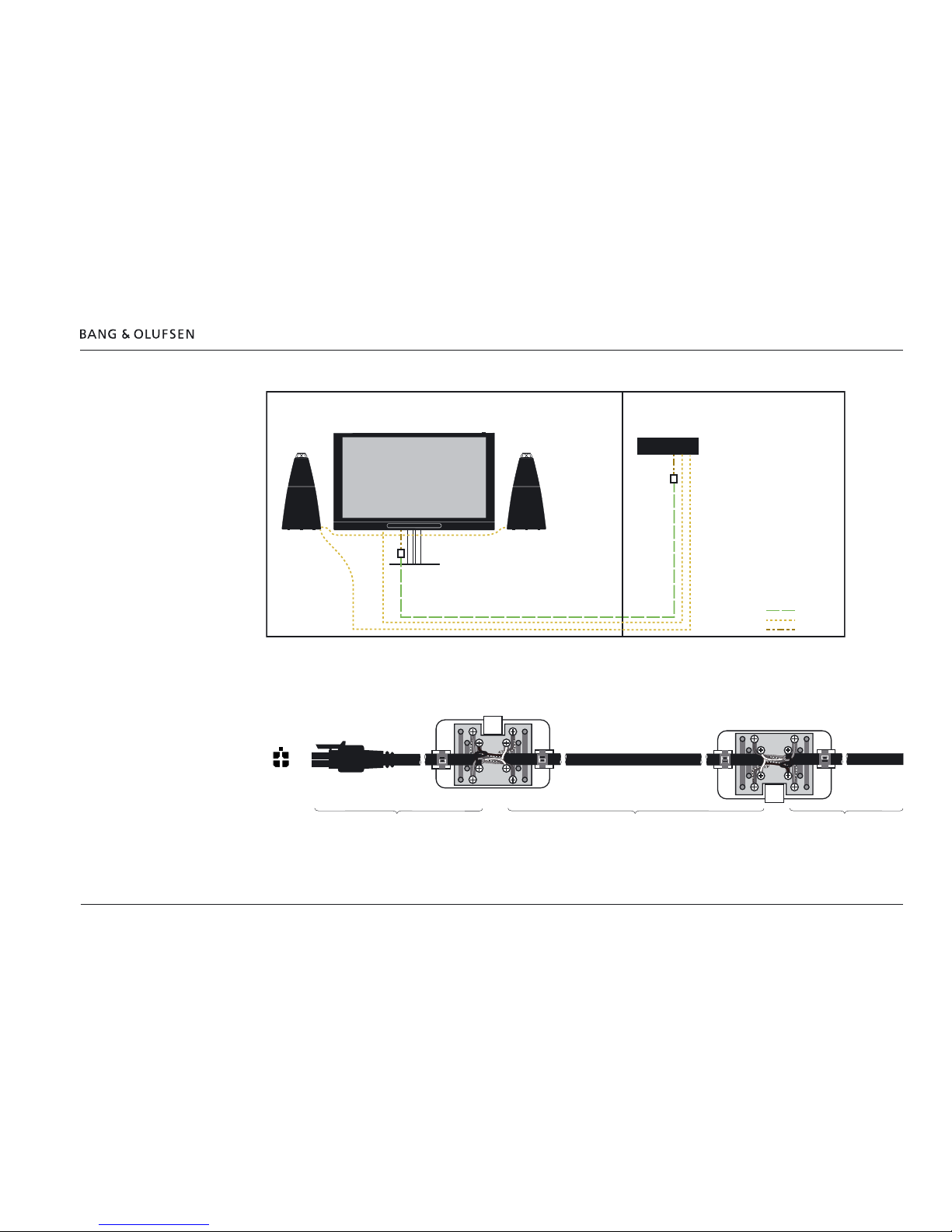
Extending cables 13
Direct cabling - visible
The CAN cable can run directly between the BeoSystem 4 and the BeoVision 12-65 in case there is no wall outlets and distribution frame. The
principle is shown in the simplied illustration above. Cable connections in the Power Link Junction Box is shown below. The junction boxes may
be hidden in the socket panel of the TV and at an appropriate place near the BeoSystem 4.
BeoSystem 4
Living room Technical room
Cat 7
Power Link
CAN
12
34
CAN plug
seen from
end of plug
CAN cable
- plug end
CAN cable
- TV end
Cat 7 cable
max. 50 m / 164 ft
CAN cable to
BeoSystem 4
CAN cable to
BeoVision 12-65
Stand
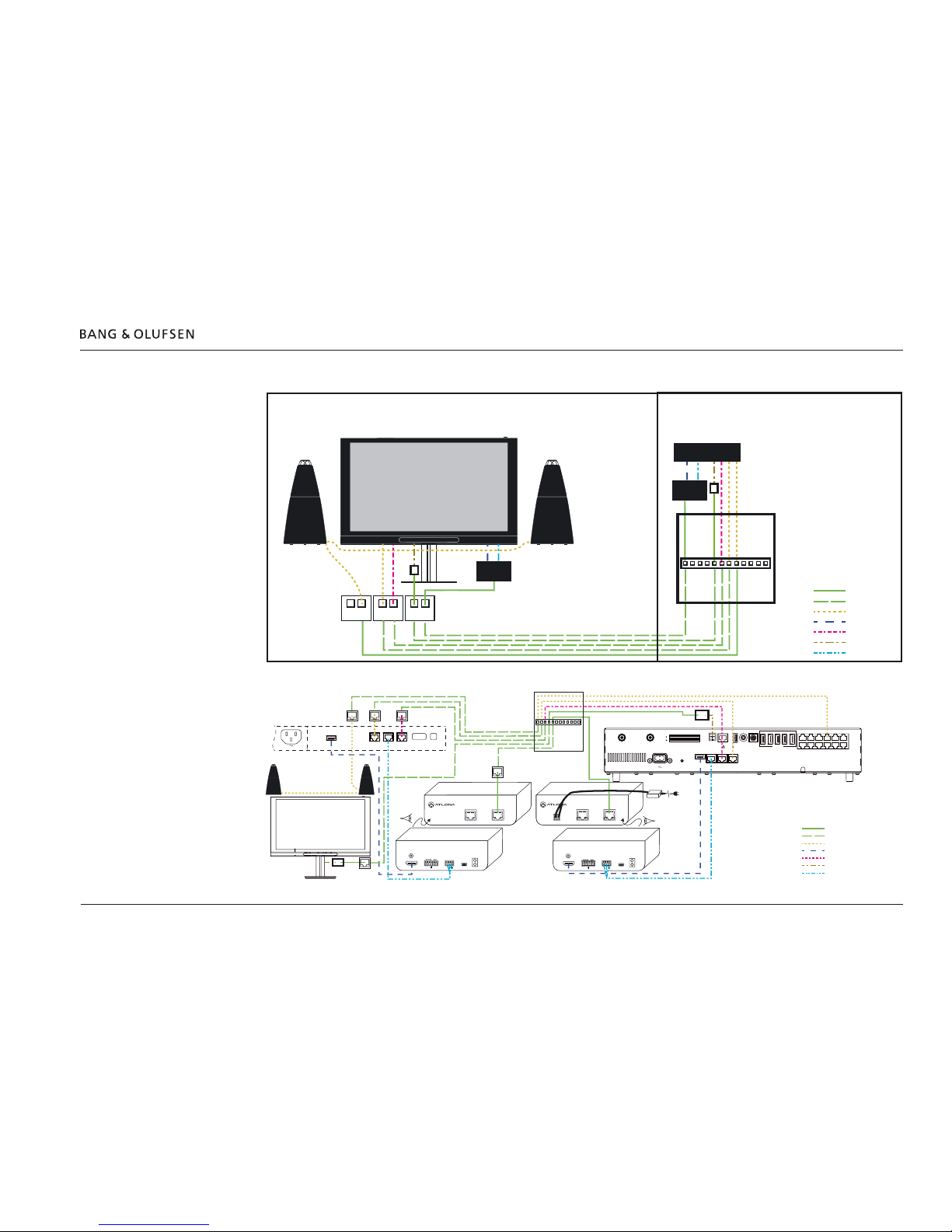
Extending cables 14
HDMI and Control Cable using Atlona AT-HDTX-RSNET / AT-HDRX-RSNET
BeoSystem 4
Extender
TX
Extender
RX
2xRJ45
2xRJ45
2xRJ45
Living room Technical room
Network Link
Cat 7
Power Link
HDMI
IR-cable
CAN
RS232
HDMI
IN
POWER
LINK
CONTROL IR Out
ACM
IR IN
®
ETHERNET
CAT5e/6/7 OUT
DC 24V
– +
FIRMWARE
HDMI IN
IR IN IR OUT
LINK
PWR IR
AT-HDTX-RSNET
POWER
– +
RS232
RX TX
®
ETHERNET
CAT5e/6/7 OUT
IR IN IR OUT
AT-HDRX-RSNET
POWER
RS232
FIRMWARELINK
HDMI OUT
PWR IR
– +
RX TX
CTRL 1CTRL 2CTRL 3
PUC 3 A+BPL 1PL 2PL 3
EXT IR PUC 1
A+B
CTRL 4
PUC 2
A+B
CTRL 5
NOT
USED
PL 4
PL 5
12345
HDMI IN
S/P-DIF
IN
5V
0,5A
12V=1.0A
STAND
COMMON INTERFACE
CHIPSIDE
CHIPSIDE
5V=50mA
AERIAL
14/18V=0.4A
SATELLITE
HDMI
OUT
MONITOR
CONTROL
IR/AUTO
CONTRAST
PL 6
AV
IN
Network Link
Cat 7
Power Link
HDMI
IR-cable
CAN
RS232
Connection panel for
BeoVision 12-65
Cabinet /
distribution frame
Cabinet /
distribution frame
Wall outlet
Floor Stand via Cat 7
and Junction Box
AT-HDRX-RSNET rear panel AT-HDTX-RSNET rear panel
AT-HDRX-RSNET front panel
AT-HDTX-RSNET front panel
BeoSystem 4
connection panel
Floor Stand
via Cat 7 and
Junction Box
Extending cables 15
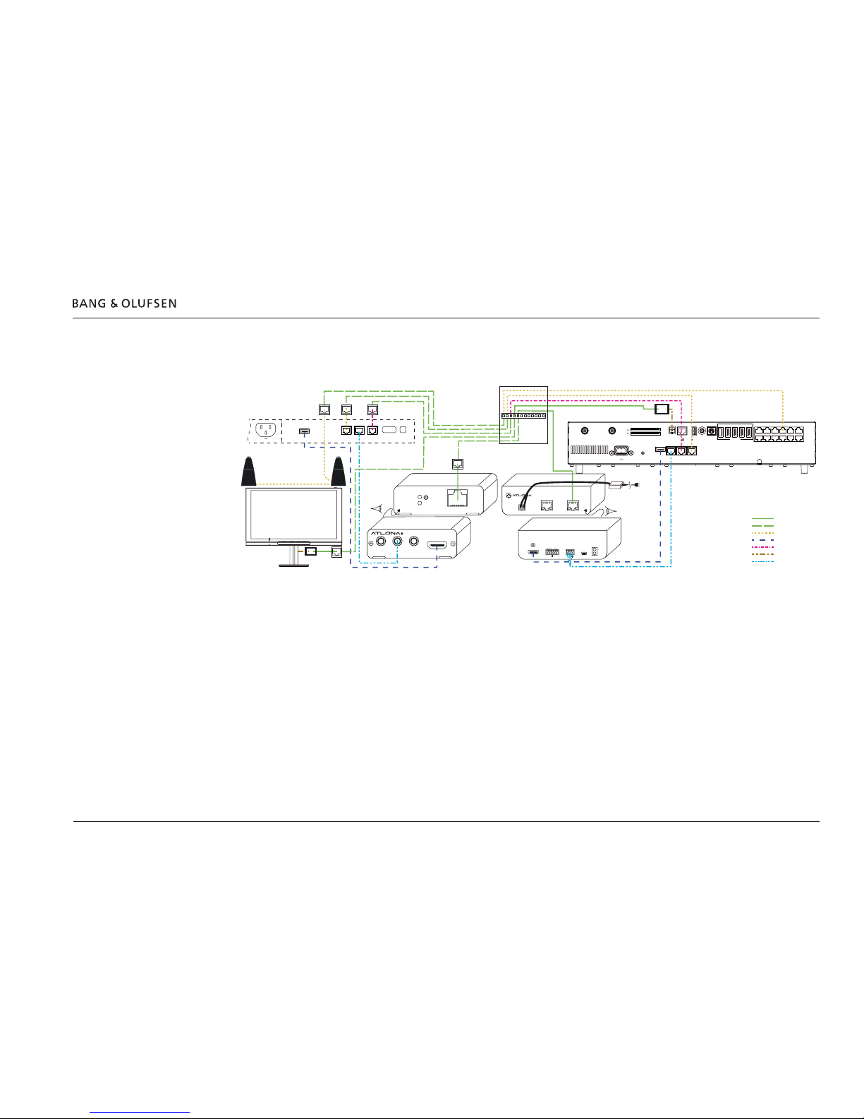
HDMI and Control Cable using Atlona AT-PRO3HDREC
The example below is similar to that of the previous page; see page 14. The only difference is that an AT-PRO3HDREC is used instead of an ATHDRX-RSNET. The AT-PRO3HDREC can be concealed in the connection panel of the BeoVision 12-65.
HDMI
IN
POWER
LINK
CONTROL IR Out
ACM
IR IN
®
ETHERNET
CAT5e/6/7 OUT
DC 24V
– +
FIRMWARE
HDMI IN
IR IN IR OUT
LINK
PWR IR
AT-HDTX-RSNET
POWER
– +
RS232
RX TX
CAT5e/6
IN
LINK
HDMI OUT
RS232 OUTIR IN IR OUT
CTRL 1CTRL 2CTRL 3
PUC 3 A+BPL 1PL 2PL 3
EXT IR PUC 1
A+B
CTRL 4
PUC 2
A+B
CTRL 5
NOT
USED
PL 4
PL 5
12345
HDMI IN
S/P-DIF
IN
5V
0,5A
12V=1.0A
STAND
COMMON INTERFACE
CHIPSIDE
CHIPSIDE
5V=50mA
AERIAL
14/18V=0.4A
SATELLITE
HDMI
OUT
MONITOR
CONTROL
IR/AUTO
CONTRAST
PL 6
AV
IN
Network Link
Cat 7
Power Link
HDMI
IR-cable
CAN
RS232
Wall outlet
Floor Stand via Cat 7
and Junction Box
BeoVision 12-65
connection panel
AT-PRO3HDREC rear panel
AT-HDTX-RSNET rear panel
AT-PRO3HDREC front panel
AT-HDTX-RSNET front panel
BeoSystem 4
connection panel
Floor Stand
via Cat 7 and
Junction Box
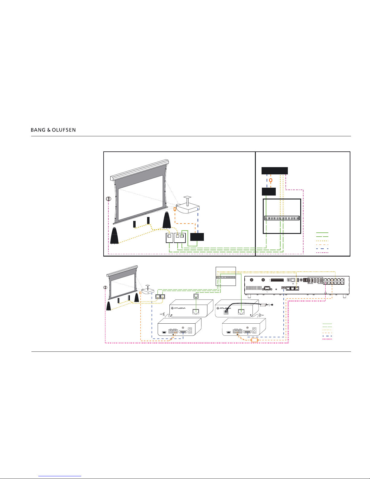
Extending cables 16
HDMI and Control Cable using Atlona AT-HDTX-IR / AT-HDRX-IR
BeoSystem 4
Extender
TX
Extender
RX
2xRJ45
2xRJ45RJ45
Living room Technical room
Network Link
Cat 7
Power Link
IR-blaster
HDMI
IR-cable
HDMI INFIRMWARE
IR IN IR OUT
LINK
PWR IR
AT-HDTX-IR
POWER
- +
®
CAT5e/6/7 OUTDC 24V
HDMI OUTFIRMWARE
IR IN IR OUT
LINK
PWR IR
AT-HDRX-IR
POWER
- +
®
CAT5e/6/7 IN
CTRL 1CTRL 2CTRL 3
PUC 3 A+B PL 1PL 2PL 3
EXT IR PUC 1
A+B
CTRL 4
PUC 2
A+B
CTRL 5
NOT
USED
PL 4
PL 5
12345
HDMI IN
S/P-DIF
IN
5V
0,5A
12V=1.0A
STAND
COMMON INTERFACE
CHIPSIDE
CHIPSIDE
5V=50mA
AERIAL
14/18V=0.4A
SATELLITE
HDMI
OUT
MONITOR
CONTROL
IR/AUTO
CONTRAST
PL 6
AV
IN
Network Link
Cat 7
Power Link
IR-blaster
HDMI
IR-cable
Cabinet /
distribution frame
Cabinet /
distribution frame
AT-HDRX-IR rear panel
AT-HDTX-IR rear panel
AT-HDRX-IR front panel
AT-HDTX-IR front panel
BeoSystem 4
connection panel
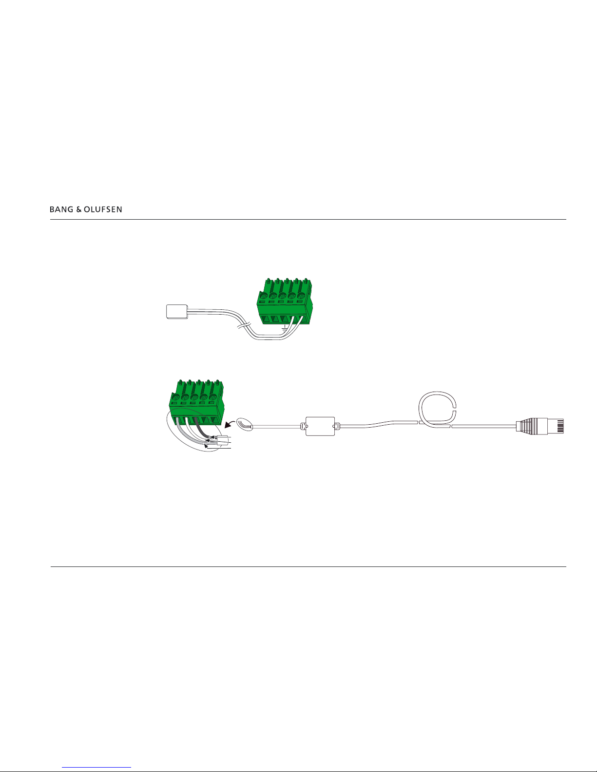
Extending cables 17
IR blaster cable - wire connections
The illustrations show the connection of the wires in the captive screw connectors with the AT-HDTX-IR / AT-HDRX-IR from Atlona.
Note: instructions in correct use of the captive screw connectors are given in the next section.
Connection of IR blaster end of cable
Connection of RJ45 end of IR blaster cable
The IR cable with optocoupler and arranged with the captive screw connector can from January 2014 be ordered as Part No.: 8780332. The cable
is used when connecting to BeoVision 11, BeoPlay V1, BeoSystem 4 and newer televisions.
Continues on next page >
PWR IR
- +
T
e
x
t
T
e
x
t
T
e
x
t
T
e
x
t
T
e
x
t
T
e
x
t
T
e
x
t
T
e
x
t
T
e
x
t
T
e
x
t
T
e
x
t
T
e
x
t
T
ext Te
x
t
T
e
x
t
T
e
x
t
T
e
x
t
T
e
x
t
T
e
x
t
PWR GND –IR +
6271240
Braided Shield
White
Red
(Bang & Olufsen Part No.: 8780332)
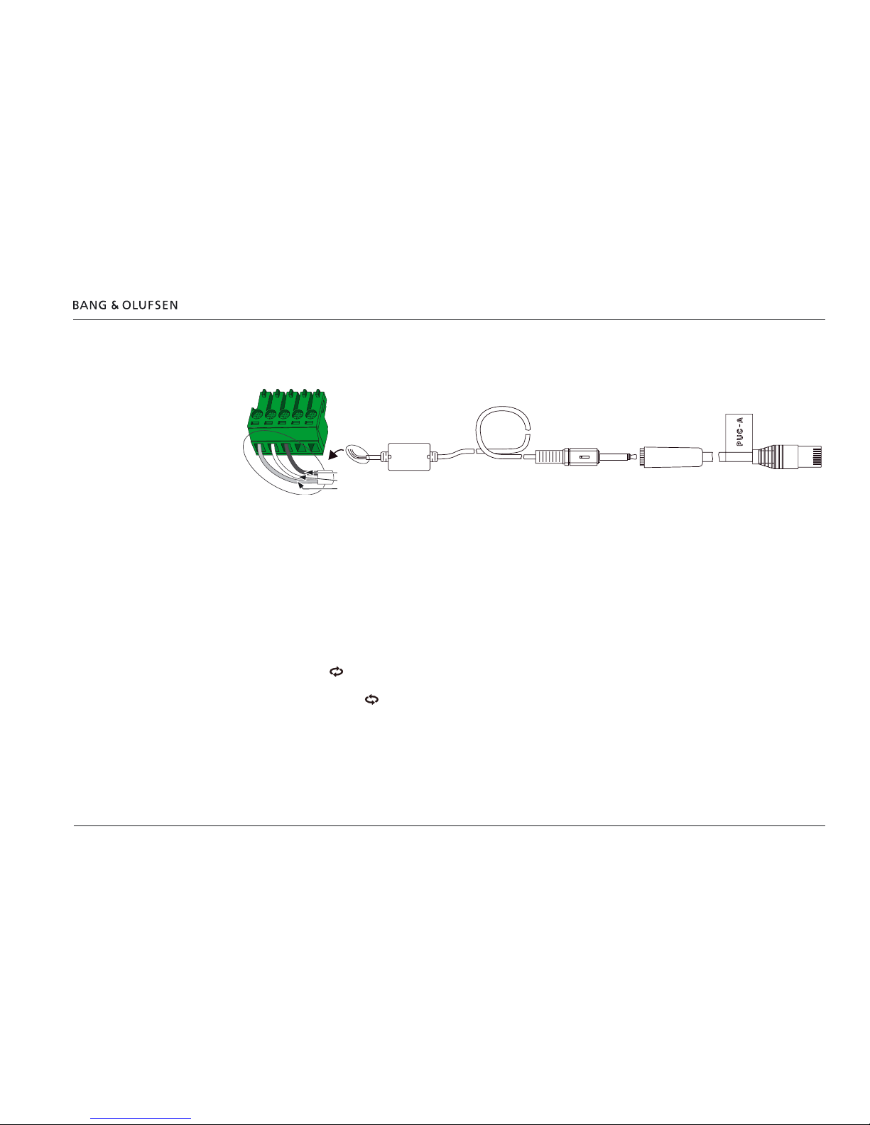
Extending cables 18
> Continued from previous page
The below description is used when connecting to older televisions and when using the IR cable with optocoupler Part No.: 6271240.
Cut off the Mini Jack 3.5 mm Stereo plug (marked: HDMI Receiver) of the IR cable with Optocoupler (Bang & Olufsen Part No. 6271240; Atlona
Part No. AT-BO-PRO3HD-1MIR).
Strip off the necessary isolation to prepare the wires for being placed in the Captive Screw Connector. Connect the wires according to the colour
indication in the below illustration. When the cable is used with BeoPlay V1, BeoVision 11 and newer TVs the Mini jack to RJ45 Adaptor cable
(Bang & Olufsen Part No. 6271233) is added.
Cable wires in captive screw connectors
With the AT-HDTX-IR and AT-HDRX-IR the cable wires are fastened in captive screw connectors that matches the connectors. This allows for
arranging cables in suitable lengths.
It is important that the wires are terminated correctly. With each connector a contact plate is placed at the top of each hole.
Follow the below instruction steps to ensure correct connection.
- Turn screw clockwise to lower contact bar.
- Insert the wire above the contact.
- Turn screw counter clockwise to raise the contact bar and screw to compress the wire against the contact plate at the top.
PWR GND –IR +
62712336271240
(Bang & Olufsen Part No.: 6271233)
Braided Shield
White
Red
(Bang & Olufsen Part No.: 6271240)
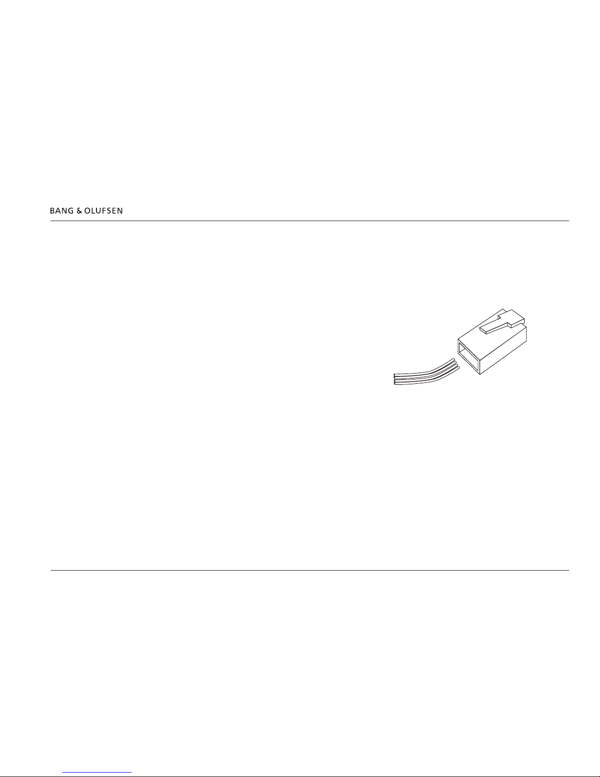
Shortening IR-blaster cables - PUC cables 19
Shortening IR-blaster cables - PUC cables
The IR-blaster cable enclosed for PUC control with the products is often too long. It is good installation practice to shorten cables to get rid of
excessive cable.
IR blaster cable with 1 IR blaster has Bang & Olufsen Part No. 6271234, marked with PUC A.
IR blaster cable with 2 IR blaster has Bang & Olufsen Part No. 6271204, marked with PUC A and PUC B for the two blasters respectively.
- Cut the cable in an appropriate length.
- Observe the text printed on the anode wire of the IR blaster cable.
- Observe the labelling of the cable (PUC A or PUC B) and arrange the two wires
according to the illustration in a new RJ45 plug.
- Crimp the wires into the RJ45 plug.
1
8
8
7
6
5
PUC A
PUC B
T
e
x
t
T
e
x
t
T
e
x
t
T
e
x
t
T
e
x
t
T
e
x
t
T
e
x
t
T
e
x
t
T
e
x
t
T
e
x
t
T
e
x
t
T
e
x
t
T
e
x
t
T
e
x
t
T
e
x
t
T
e
x
t
T
e
x
t
T
e
x
t
T
e
x

Screen measurement 20
Screen measurement
The easiest way to do the screen measurement is by having the BeoSystem 4 within 1.8 m/6 ft distance from the BeoVision 12-65 if at all possible.
If this is not possible, see “Distance between BeoSystem 4 and BeoVision 12-65” below.
Screen measurement - introduction
The BeoSystem 4 requires some measurements to be made to match it to the BeoVision display it is connected to. These measurements consist of
two measurement sequences:
- MEASURE SCREEN: a measurement of the colour reproduction of the BeoVision display.
- MEASURE LIGHT SENSOR: a measurement of the ambient light sensor of the BeoVision display.
Prerequisite
The measurement involves the use of a reference measurement device, taken into use during installation by the installer. The reference
measurement device is part of the Calibration kit BeoSystem 4; Bang & Olufsen Part No. 3376493.
If the screen measurement is not made, the following text will be shown each time the television is switched On:
SCREEN NOT MEASURED
PLEASE CONTACT YOUR INSTALLER
Distance between BeoSystem 4 and BeoVision 12-65
Due to the length of the cable of the measurement device the distance between the BeoVision 12-65 and the BeoSystem 4 must be no more than
1.8 m/6 ft.
If the distance is longer, a USB extension cable must be used so that the measurement device can be connected to the USB socket of the
BeoSystem 4. When USB extension cables longer than 5 m/16 ft are needed, they must be USB Active Extension Cables.
Initiating the Screen Measurement
Automatically
- Insert the USB plug of the measurement device into the USB socket of the BeoSystem 4. The screen measurement function is then presented
automatically. The following text is shown as acknowledgement: MEASUREMENT DEVICE DETECTED, and one of the following two actions can
be chosen followed by pressing the Centre button:
- DO NOTHING: the system reverts to presenting the selected source.
- PERFORM MEASUREMENT: see Screen measurement page 21.
Via Customer Service Menu
In case the screen measurement menu does not show automatically or the measurement is to be initiated manually do the following to get to the
screen measurement menu. It is a prerequisite that the USB plug of the measurement device is inserted into the USB socket of the BeoSystem 4.
- On the remote control press MENU > SETUP and press the Red button and within 3 seconds press the Centre button.
- Select PICTURE ADJUSTMENT > SCREEN MEASUREMENT.
- Select SCREEN MEASUREMENT and press the Centre button.
Screen measurement 21
Screen measurement - start menu
The following is a step-by-step instruction of the Screen measurement cycle.
- Initiate the screen measurement cycle automatically or via the Customer Service menu; see page 20.
The following is shown:
The SCREEN MEASUREMENT dialogue gives a status as follows:
SCREEN NOT MEASURED / MEASURED (depending on if a screen measurement has been completed).
LIGHT SENSOR NOT MEASURED / MEASURED (depending on if a ambient light measurement has been completed).
MEASUREMENT DEVICE NOT CONNECTED / CONNECTED (depending on if the measurement device is detected via the USB socket).
MEASURE SCREEN
MEASURE LIGHT SENSOR
- Select either of the two measurement cycles: MEASURE SCREEN, see page 22 or MEASURE LIGHT SENSOR, see page 24.

Screen measurement - Measure Screen 22
MEASURE SCREEN - sequence
- Select MEASURE SCREEN and press the Centre button.
The following is shown:
ROTATE THE DIFFUSER AWAY FROM
THE LENS BEFORE STARTING AND
PLACE SENSOR ON THE GREEN
SQUARE NOT OVERLAPPING THE RED
AREA.
ONCE POSITIONED CORRECTLY YOU
WILL BE ABLE TO PRESS START AND
INITIATE SCREEN MEASUREMENTS.
Ambient light condition
Perform the screen measurements in lighting conditions as dark as possible to minimise the inuence of ambient light.
Warm up sequence
- If the BeoVision 12-65 has not been switched On for 5 minutes, a warm up sequence is started, indicated by the following text:
A WARM UP SEQUENCE OF 5
MINUTES WILL BE SHOWN BEFORE
STARTING ACTUAL MEASUREMENTS.
In the warm up period, the picture will show coloured pixels. When the warm up period is ended continue on next page.
- If the BeoVision 12-65 has been switched On for 5 minutes or more continue on next page.
√
X
Screen measurement - Measure Screen 23
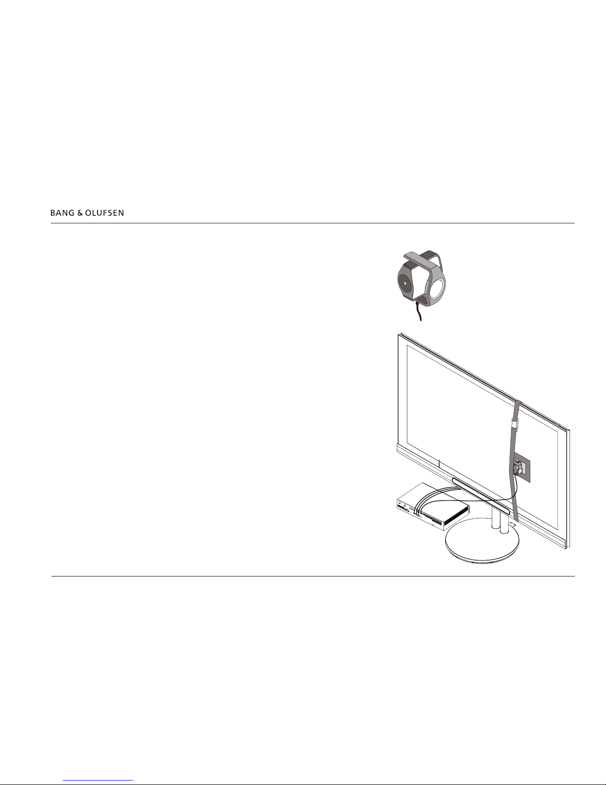
Start measurement
- Follow the instructions from the previous page:
- Turn the diffuser away from the lens; see illustration.
- Place the elastic strap around the BeoVision 12-65 and the measurement
device as shown in the illustration. The elastic strap must be tightened using
the plastic buckle.
- Make sure that the measurement device is pressed rmly and perpendicularly
to the screen surface, minimising the inuence of the ambient light.
- Place the measurement device so that the lens is inside the green area on
the screen and it is kept xed in a steady position by the elastic strap.
The START MEASUREMENT function will rst be highlighted when the lens
is in a proper position.
- Press the Centre button to start the measurement.
The measurement sequence measures various intensities of white and a
number of colours.
Note: The measurement sequence takes up to 4 minutes. Do not touch the
measurement device during this period!
When completed the following text is shown in the lower right corner of the
screen:
SCREEN MEASUREMENT PERFORMED SUCCESSFULLY
The sequence returns to the SCREEN MEASUREMENT menu with the
MEASURE LIGHT SENSOR highlighted.
In case the measurement fails an error message will be shown.
In that case, check and reposition the measurement device assuring it is pressed
rmly and perpendicularly to the screen and make sure that the lighting
conditions in the room are as dark as possible. After this the above
measurement must be made again.
Screen measurement - Measure Screen 24
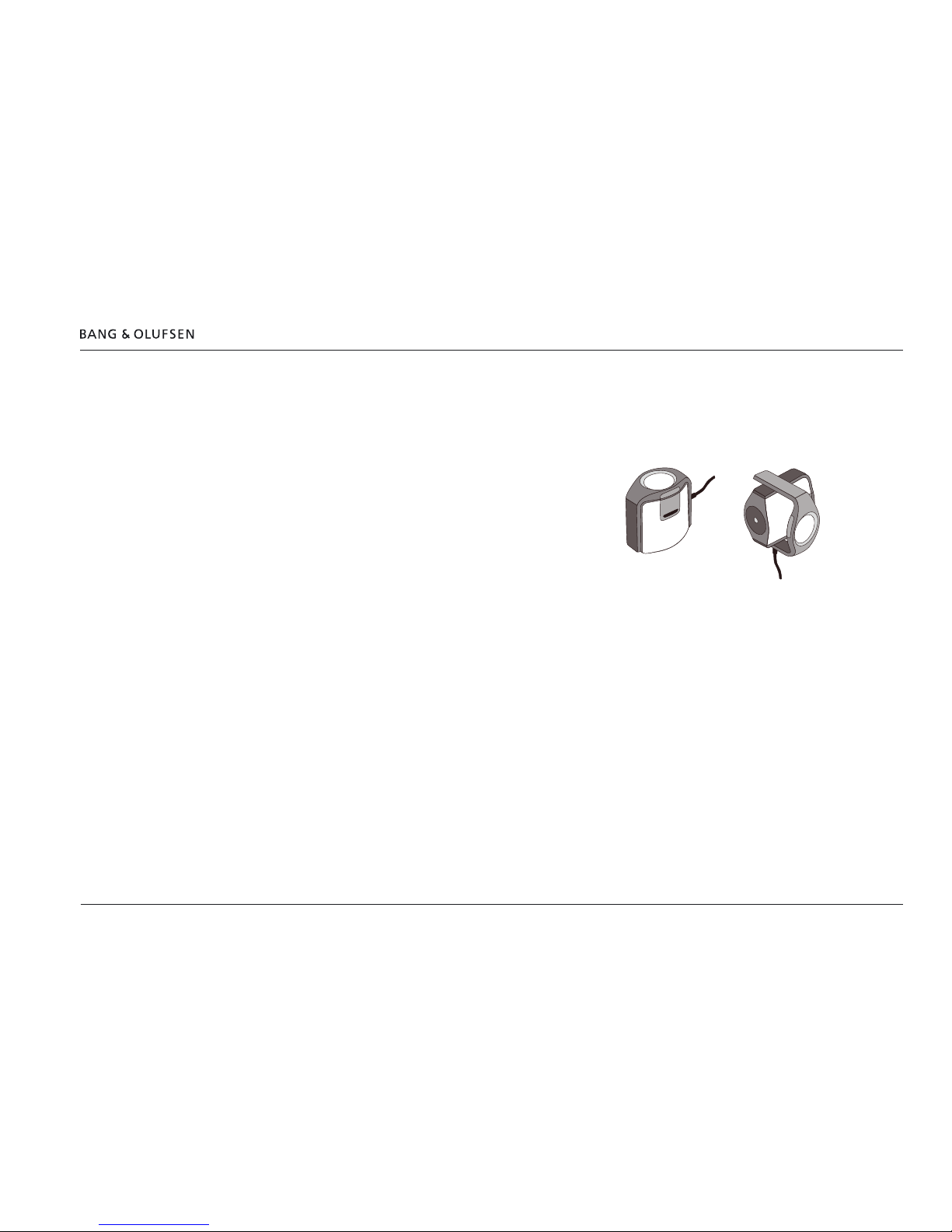
MEASURE LIGHT SENSOR - sequence
- With the MEASURE LIGHT SENSOR function highlighted, press the Centre button to start the measurement.
The following instructions are shown - follow these:
PREPARATION:
ROTATE THE DIFFUSER OVER THE
LENS BEFORE STARTING, REFER TO
THE DRAWINGS IN THE
INSTALLATION GUIDE
CONTINUE
Ambient light condition
Perform the screen measurements in lighting conditions as bright as possible, but without light sources shining directly onto the light sensor of the
BeoVision 12-65 as well as the light sensor of the reference measurement device.
Also the light sensor of the BeoVision 12-65 as well as the light sensor of the measurement device should not point towards window or any light
source.
The illuminance (light intensity) should be between 800 and 1000 lux. Unfortunatly there is no read out of the illuminance. As a rule of thumb it is
dim the light, sufcient for reading text on a piece of paper.
√
X
Screen measurement - Measure sensor step 1 of 4 25
Step 1 of 4
Note: See recommendations regarding ambient light conditions on the previous page.
The recommendations are important to be followed for a succesful measurement as described in the next 4 steps. An error message will be given
at step 4 if conditions are not satisfactory. Then adjust light conditions and redo the measurement.
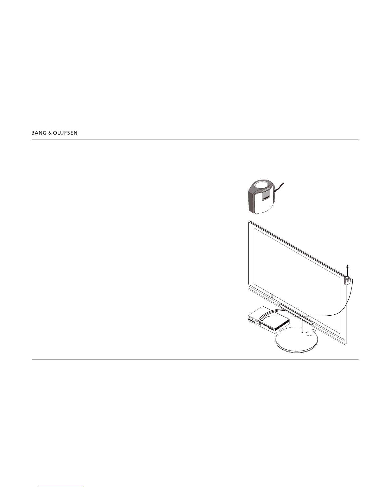
For this measurement, the measurement device is oriented as seen in the
illustration.
The measurement device is held by hand.
- Press the Centre button to continue
The following instructions are shown - follow these (see the illustration):
STEP 1 OF 4:
HOLD/ATTACH THE MEASURING
DEVICE AGAINST THE SCREEN’S
UPPER RIGHT EDGE, POINTING THE
DEV ICE UPWARDS
START MEASUREMENT NO. 1
- Press the Centre button to start the measurement.
During the measurement the text MEASURING is shown.
When the measurement is nished, continue with step 2.
 Loading...