

Page 1
UL 61010-1
Product Leadership • Training • Service • Reliability
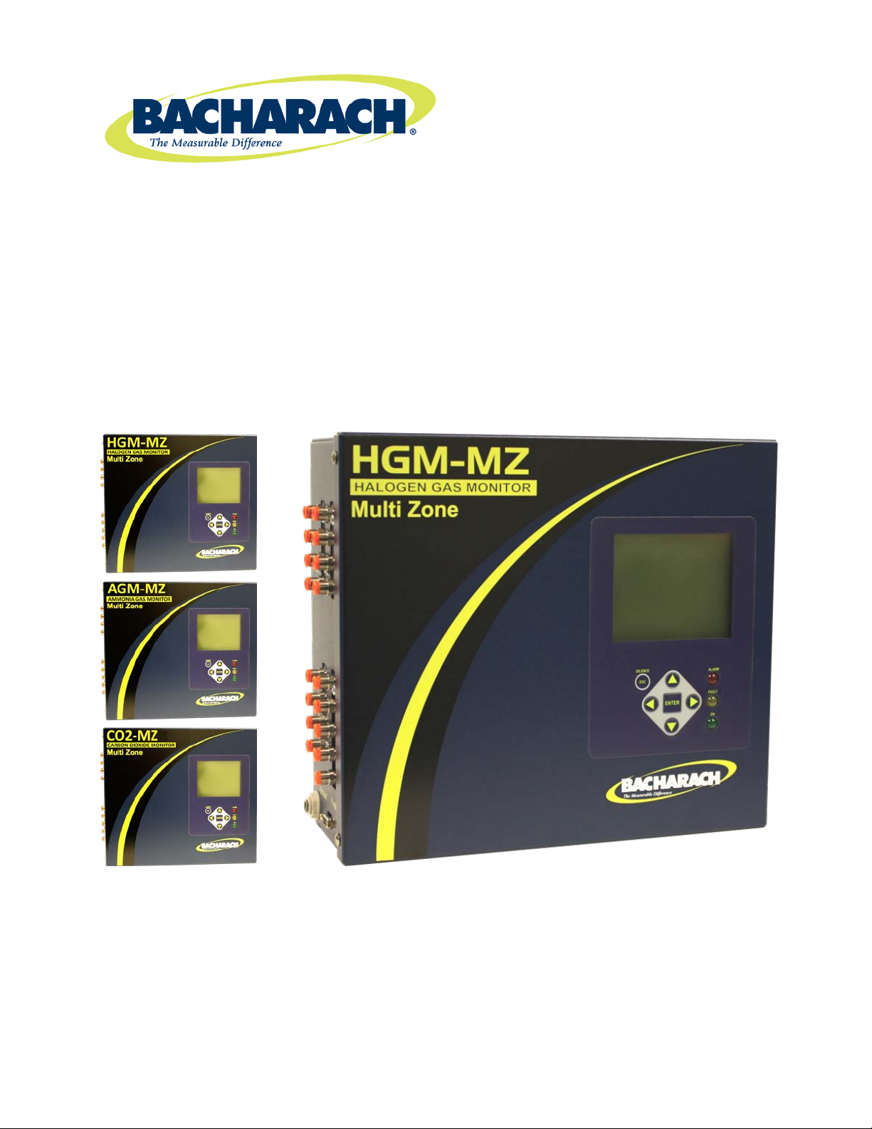
MultiZone Gas Monitors
• HGM-MZ (Halogen)
• AGM-MZ (Ammonia)
• CO2-MZ (Carbon Dioxide)
Installation • Operation • Maintenance
CAN/CSA 22.2 No. 61010.1
EN 14624
Instruction P/N: 3015-5074
Rev. 13
January 2015
Page 2

Multi-Zone Gas Monitors
WARRANTY
Bacharach, Inc. warrants to Buyer that at the time of deliver y this Product will be free from defects in
material and manufacture and will conform substantially to Bacharach Inc.’s applicable specifications.
Bacharach’s liabilit y and Buyer’s remedy under this warranty are limited to the repair or replacement, at
Bacharach’s option, of this Product or parts thereof returned to S eller at the factor y of manufacture a nd
shown to Bacharach Inc .’s reasona ble satisfacti on to have been defective; prov ided that written notice of
the defect shall have been given b y Buyer to Bachara ch Inc. with in two (2) years after the dat e of delivery
of this Product by Bacharach, Inc.
Bacharach, Inc. warrants t o Buyer that it will convey good title to this Produc t. Bacharach’s liabilit y and
Buyer’s remedy under this warrant y of title are limited to the removal of any title defec ts or, at the elec tion
of Bacharach, to the replacement of this Product or parts thereof that are defective in title.
The warranty set f or th in P aragr ap h 1 does not app ly to parts that the Operating Ins truc tions desig nat e as
having a limited shelf-life or as being expended in normal use (e.g., filters).
THE FOREGOING WARRANT IES ARE EX CLUSI VE AND AR E GIVEN AN D ACCEPT ED IN LIEU OF (I)
ANY AND ALL OTHER WARRANTIES, EX PRESS OR IMPLIED, IN CLUDING WITHOUT LIMIT ATION
THE IMPLIED WARRANTIES OF MERCHANTABILITY AND FITNESS FOR A PARTICULAR
PURPOSE: AND (II) ANY OBLIGATION, LIABILITY, RIGHT, CLAIM OR REM EDY IN CONTRACT OR
TORT, WHETHER OR NOT ARISING FROM BACHARACH’S NEGLIGENCE, ACTUAL OR IMPLIED.
The remedies of the Bu yer shall be limited to thos e provided herein t o the exclusion of any and all other
remedies including, without limitation incidental or consequential damages. No agreement varying or
extending the foregoing wa r ranties , r emedies or this limitation will be binding upo n Bac har ac h, Inc . un les s
in writing, signed by a duly authorized officer of Bacharach.
Register your warranty by visiting
Product improvements and enhancements are continuous; therefore the specifications and information
contained in this document may change without notice.
Bacharach, Inc. shall not be liable for errors contained herein or for incidental or consequential damages
in connection with the furnishing, performance, or use of this material.
Copyright © 2000–2015, Bacharach, Inc., All Rights Reserved
No part of this document may be photocopied, reproduced, or translated to another language without the
®
BACHARACH
is a registered trademark of Bacharach, Inc. All other trademarks, trade names,
service marks and logos referenced herein belong to their respective owners.
www.MyBacharach.com
Patent 6,590,690
prior written consent of Bacharach, Inc.
ii P/N: 3015-5074 Rev 13
Page 3

Multi-Zone Gas Monitors
Table of Contents
SECTION 1. INTRODUCTION..................................................................................................................... 1
1.1. About This Manual .............................................................................................................................. 1
1.2. Warnings and Cautions ....................................................................................................................... 1
1.3. Safety Precautions .............................................................................................................................. 1
1.3.1. Ha zardous Areas .................................................................................................................... 1
1.3.2. Combustible and Flammable Gases ...................................................................................... 2
1.3.3. AC Power Supply ................................................................................................................... 2
1.3.4. Protective Grounding .............................................................................................................. 2
1.3.5. Explosive Atmosphere ............................................................................................................ 2
1.3.6. Proper Exhaust Venting ......................................................................................................... 2
1.3.7. Accessing the Interior of the Monitor ...................................................................................... 2
1.3.8. Misuse and Modifications to the Instrument ........................................................................... 3
1.3.9. In Case of Malfunction ............................................................................................................ 3
1.3.10. Fusing ..................................................................................................................................... 3
1.3.11. Installation Category ............................................................................................................... 3
1.3.12. Altitude Limit ........................................................................................................................... 3
1.3.13. Cleaning ................................................................................................................................. 3
1.4. Key External Hardware Components .................................................................................................. 4
1.5. Functional Overview ............................................................................................................................ 4
1.5.1. General Description ................................................................................................................ 4
1.5.2. Communications Options ....................................................................................................... 5
1.5.3. Understanding Monitor ing Levels ........................................................................................... 5
1.5.4. Response to the Presence of Multiple Refrigerants (HGM Only) .......................................... 5
1.5.5. Suggested Location of Sampling Points ................................................................................ 5
1.5.6. Locating a Remote Display (Optional) ................................................................................... 6
1.6. Specifications ...................................................................................................................................... 7
SECTION 2. INSTALLATION ...................................................................................................................... 9
2.1. Installation Considerations .................................................................................................................. 9
2.1.1. Warnings and Cautions .......................................................................................................... 9
2.1.2. Inspection ............................................................................................................................... 9
2.1.3. Location of the Monitor ........................................................................................................... 9
2.1.4. Mounting Instructions ............................................................................................................. 9
2.2. Connecting Gas Sample Lines .......................................................................................................... 10
2.2.1. Overview............................................................................................................................... 10
2.2.2. Tubing Considerations ......................................................................................................... 11
2.2.3. Connecting Purge Line ......................................................................................................... 11
2.2.4. Connecting Exhaust Line ..................................................................................................... 11
2.2.5. Connecting Sample Intake Lines ......................................................................................... 11
2.2.6. Installing an Optional Splitter Kit .......................................................................................... 12
2.2.7. Connecting the Water Trap .................................................................................................. 12
2.3. Interior Components .......................................................................................................................... 13
2.4. Electrical Wiring ................................................................................................................................. 13
2.5. Connecting Communications Devices .............................................................................................. 15
2.5.1. Remote Display Module (RD) Connection ........................................................................... 15
2.5.2. Integrating with Building Management Systems .................................................................. 15
2.5.3. Larger Integrated Systems ................................................................................................... 15
2.5.4. Changing Terminator Switch Settings .................................................................................. 16
2.5.5. Personal Computer .............................................................................................................. 16
2.6. Terminating Multiple Mo nit or s ........................................................................................................... 17
2.7. Connecting to a Building Management System ................................................................................ 17
2.8. PC Software ...................................................................................................................................... 18
2.8.1. Operation .............................................................................................................................. 18
P/N: 3015-5074 Rev 13 iii
Page 4

Multi-Zone Gas Monitors
2.8.2. Saving and Sending Program s ............................................................................................ 20
2.8.3. Trend Data ........................................................................................................................... 20
2.8.4. Converting the TREND Text File to a Microsoft Excel File .................................................. 20
2.8.5. Saving and Printing Screens and Logs ................................................................................ 20
2.8.6. USB Type Laptops ............................................................................................................... 20
2.9. Optional Current Loop Interfaces ...................................................................................................... 21
2.9.1. Optional 4–20 mA DC Outputs ............................................................................................. 21
2.9.2. 4-20 mA DC Connections..................................................................................................... 22
2.10. Connecting External Alarms .............................................................................................................. 23
2.10.1. Overview............................................................................................................................... 23
2.10.2. Connection ........................................................................................................................... 23
SECTION 3. SETUP PROGRAMMING ..................................................................................................... 25
3.1. Initial Power Up ................................................................................................................................. 25
3.2. Data Display Screen .......................................................................................................................... 25
3.3. Navigating to the 1st Setup Screen ................................................................................................... 25
3.4. Navigating to the 2nd Setup Screen ................................................................................................. 25
3.4.1. Location ................................................................................................................................ 26
3.4.2. Number of Zones Installed ................................................................................................... 26
3.4.3. Alarm Acknowledge Mode.................................................................................................... 26
3.4.4. Audible Alarm ....................................................................................................................... 26
3.4.5. Zone Hold ............................................................................................................................. 27
3.4.6. Detection Limit ...................................................................................................................... 27
3.4.8. Loop Mode ........................................................................................................................... 27
3.4.7. Loop2 Factor ........................................................................................................................ 27
3.4.9. Re-Zero Mode ...................................................................................................................... 28
3.5. Navigating to the 3rd Setup Screen .................................................................................................. 28
3.5.1. Overview............................................................................................................................... 28
3.5.2. Baud Rate ............................................................................................................................ 28
3.5.3. Node Address ....................................................................................................................... 28
3.5.4. Password .............................................................................................................................. 28
3.6. Additional Service Features .............................................................................................................. 29
3.6.1. Service Timeout ................................................................................................................... 29
3.6.2. DET Digipot .......................................................................................................................... 29
3.6.3. Node Address ....................................................................................................................... 30
3.6.4. Sensor Temperature Coefficient (For Factory Use Only) .................................................... 30
3.6.5. Password .............................................................................................................................. 30
3.6.6. Acquiring Temperature Coefficient (For Factory Use Only) ................................................. 30
3.6.7. IR Digipot .............................................................................................................................. 30
3.7. Establishing the CO
Sensor Baseline .............................................................................................. 30
2
SECTION 4. GENERAL OPERATION ...................................................................................................... 31
4.1. Functional Overview .......................................................................................................................... 31
4.2. The Zone Setup Screen .................................................................................................................... 31
4.2.1. Location ................................................................................................................................ 31
4.2.2. Gas/Refrigerant Type ........................................................................................................... 31
4.2.3. Distance................................................................................................................................ 32
4.2.4. Zone Temperature ................................................................................................................ 32
4.2.5. Current Detection Reading ................................................................................................... 32
4.2.6. Log Interval ........................................................................................................................... 32
4.3. Navigating to the 2nd Zone Setup Screen ........................................................................................ 32
4.3.1. Leak Level ............................................................................................................................ 33
4.3.2. Spill Level ............................................................................................................................. 33
4.3.3. Evacuation Level .................................................................................................................. 33
4.3.4. Re-Setting the Peak PPM Value .......................................................................................... 33
4.4. Alarms ............................................................................................................................................... 33
iv P/N: 3015-5074 Rev 13
Page 5

Multi-Zone Gas Monitors
4.4.1. Functional Overview ............................................................................................................. 33
4.4.2. Responding to Alarms .......................................................................................................... 34
4.4.3. Alarm Detail Screen ............................................................................................................. 34
4.4.4. Acknowledging Alarms ......................................................................................................... 35
4.4.5. Silencing an Alarm ............................................................................................................... 35
4.4.6. Clearing the Alarm Event Log .............................................................................................. 36
4.5. System Faults .................................................................................................................................... 36
4.5.1. Functional Overview ............................................................................................................. 36
4.5.2. Navigating to the Fault Screen ............................................................................................. 37
4.5.3. Critical Faults ........................................................................................................................ 37
4.5.4. Non Critical Faults ................................................................................................................ 38
4.5.5. Reset to Factory Default Settings ........................................................................................ 38
4.5.6. Clearing System Faults ........................................................................................................ 38
4.5.7. Viewing Fault Log ................................................................................................................. 39
4.5.8. Viewing Flow Log ................................................................................................................. 39
4.6. The Trend Screen ............................................................................................................................. 40
4.6.1. Navigating to the Trend Screen ........................................................................................... 40
4.7. The Calibration Screen ...................................................................................................................... 40
4.7.1. Overview............................................................................................................................... 40
4.7.2. Navigating to the Calibration Screen .................................................................................... 41
4.7.3. Calibration Procedure (HGM and AGM Only) ...................................................................... 41
4.7.4. Adjusting Calibration Factor (HGM and AGM Only) ............................................................ 41
4.7.4. CO
Atmospheric Concentration .......................................................................................... 42
2
4.7.6. Programming New Gases (HGM Only) ................................................................................ 42
4.8. Zone Hold Mode .................................................................................................................................. 43
4.9. The Diagnostic Screen ...................................................................................................................... 44
4.9.1. Navigating to the Diagnostic Screen .................................................................................... 44
4.9.2. Diagnostic Screen Overview ................................................................................................ 45
SECTION 5. MAINTENANCE.................................................................................................................... 47
5.1. Replacement Parts Overview ............................................................................................................ 47
5.2. Replacement Parts and Optional Accessories .................................................................................. 48
5.3. Troubleshooting ................................................................................................................................. 50
APPENDIX A. RECOMMENDED REFRIGERANT GAS ALARM SETTINGS ........................................ 53
APPENDIX B. RS-485 COMMUNICATIONS PROTOCOL ..................................................................... 55
B.1. Overview ............................................................................................................................................ 55
B.2. MODBUS RTU Protocol .................................................................................................................... 55
B.3. MZ MODBUS RTU Operation ........................................................................................................... 55
B.3.1. Overview............................................................................................................................... 55
B.3.2. Protocol Details .................................................................................................................... 55
B.3.3. MZ Monitor Polling ............................................................................................................... 56
B.3.4. Network Topologies .............................................................................................................. 56
B.3.5. Key Comm Protocol Parameters .......................................................................................... 56
B.3.6. MODBUS Exception Responses .......................................................................................... 57
B.3.7. MODBUS Gas Enumeration................................................................................................. 57
B.4. Standard Register Summary ............................................................................................................. 58
B.4.1. Dynamic Register Summary (2000 Series; R; Function Code 03) ...................................... 58
B.4.2. Dynamic Register Summary (2000 Series; R; Function Code 03) ...................................... 59
B.5. Block Mode Register Summary ......................................................................................................... 62
B.5.1. Summary of Registers .......................................................................................................... 62
B.5.2. System Data Register 0x0010 (16 Dec) (R/W, 54 Bytes) .................................................... 62
B.5.3. Status Register 0x001 (17 Dec) (R/W, 10 Bytes) ................................................................ 63
B.5.4. Fault Code Table .................................................................................................................. 64
B.5.5. Zone Data Register 0x12xx (R/W, 78 Bytes) ....................................................................... 64
P/N: 3015-5074 Rev 13 v
Page 6

Multi-Zone Gas Monitors
B.5.6. Alarms and Alarm Acknowledge .......................................................................................... 65
B.5.7. Date Time Register 0x0015 (21 Dec) (R/W, 14 Bytes) ........................................................ 65
B.5.8. Sensor Data Register 0x0016h (22 Dec) (R, 82 Bytes) ....................................................... 66
B.5.9. Release Zone Hold Register 0x0017h (23 Dec) (W, 10 Bytes) ........................................... 66
B.5.10. Hold Zone Register 0x0018h (23 Dec) (W, 10 Bytes) .......................................................... 66
B.5.11. MZ Hold Mode ...................................................................................................................... 66
B.5.12. Fault Log Register 0x1900-01 (6400-6401 Dec) (R, 302 Bytes).......................................... 67
B.5.13. Flow Log Register 0x001F (31 Dec) (R, 142 Bytes) ............................................................ 67
B.5.14. Alarm Log Register 0x1A00-02 (6656-58 Dec) (R, 582 Bytes) ............................................ 67
B.5.15. Service Mode Register 0x001B (27 Dec) (W, 10 Bytes) ...................................................... 67
B.5.16. Release Service Mode 0x001C (28 Dec) (W, 10 Bytes) ...................................................... 67
B.5.17. MZ Service Mode ................................................................................................................. 68
B.5.18. PPM Register 0x001E (30 Dec) (R, 32 Bytes) ..................................................................... 68
B.5.19. Zone Log Registers 0x3xyy (R, 1502 Bytes)........................................................................ 68
APPENDIX C. SYSTEM MENU MAP ....................................................................................................... 69
APPENDIX D. AGENCY APPROVALS ................................................................................................... 73
APPENDIX E. SERVICE CEN T ER S ........................................................................................................ 75
INDEX ......................................................................................................................................................... 77
vi P/N: 3015-5074 Rev 1 3
Page 7
Multi-Zone Gas Monitors
SECTION 1. INTRODUCTION
1.1. About This Manual
Thank you for investing in a Bacharach Multi-Zone Gas Monitor. To assure operator safety and the proper
use of the monitor please read this manual. It provides important information on the installation, operation,
maintenance, and servicing of the monitor and display module.
If you have a working knowledge of your gas monitor, you will find this manual useful as a reference tool. If
you are new to the use of gas monitors, this document is educational in the principles of gas detection and
the proper operation of this device.
1.2. Warning and Cauti on Conventions
When used in this manual or as labeled on the gas monitor, the following hazard symbols and/or
associated words are defined as follows.
WARNING: This symbol and/or the use of the word WARNING indicates a potential
hazard associated with the use of this equipment. It calls attention to a procedure,
practice, condition, or the like, which if not correctly performed or adhered to, could result
in death or serious injury.
WARNING: This symbol and/or the use of the word WARNING indicates a potential
hazard from electrical sh o ck. It calls attention to a procedure, practice, condition, or the
like, which if not correctly performed or adhered to, could result in death or serious injury.
CAUTION: This symbol and/or the use of the word CAUTION indicates a potential hazard
associated with the use of this equipment. It calls attention to a procedure, practice,
condition, or the like, which if not correctly performed or adhered to, could result in minor or
moderate injury.
IMPORTANT: The use of the word IMPORTANT in this manual calls attention to a
procedure, practice, condition, or the like, which if not correctly performed or adhered to,
could result in incorrect performance of or damage to the equipment and may void the
warranty.
1.3. Safety Precautions
WARNING: This instrument has not been designed to be intrinsically safe for use in areas
classified as hazardous locations. For your safety, DO NOT
locations.
WARNING: This is NOT a safety device. Some gases which this instrument can detect
may be combustible/flammable. When properly configured, this instrument is designed to
alarm at concentrations that are lower than the explosive limit of the gas. As such, it is the
buyer’s responsibility to initiate an immediate planned response to any gas leaks as soon
as they are detected. This equipment should NEVER be used to measure or sample
gases at or above their respective lower explosive limits.
IMPORTANT: The gas monitor uses a universal power supply that is capable of accepting
inputs of 100 to 240 VAC, 50/60 Hz. The monitor’s power consumption is 20 Watts. It is
highly recommended that the monitor be connected directly to the AC power source,
preferably on its own circuit with UPS or surge protection.
P/N: 3015-5074 Rev 13 1
use it in hazardous (classified)
Page 8

Multi-Zone Gas Monitors
WARNING: A switch or circuit breaker must be included in the building installation. The
switch must be in close proximity to the monitor and within easy reach of the operator. The
switch must be clearly marked as the disconnecting device for the equipment.
WARNING: Under no circumstances should the monitor be operated without connection
to a protective ground. Doing so poses a potential shock hazard and is also a violation of
electrical safety standards applicable to this type of equipment.
WARNING: Do not operate this equipment in the presence of flammable liquids, vapors,
or aerosols. Operation of any electrical instrument in such an environment constitutes a
safety hazard.
WARNING: It is imperative that the exhaust port on this instrument be properly vented as
described in this manual. Failure to do so may constitute a safety hazard.
WARNING: Extreme care should be exercised when accessing the interior of the monitor.
Only qualified electrical maintenance personnel should make connections and perform
adjustments. Always remove AC power before opening the monitor’s enclosure.
WARNING: The protection provided by the monitor may be impaired if the monitor is used
in a manner not specified by Bacharach, Inc. Modifications to this monitor, not expressly
approved, will void th e warranty.
WARNING: Do not continue to use this equipment if there are any symptoms of
malfunction or failure. In the case of such occurrence, de-energize the power supply and
contact a qualified repair technician or the nearest Bacharach Service Center.
WARNING: This device uses type “F” fuses (F1 and F2) rated at 1.0 A, 250 VAC.
Replace ONLY with Bacharach-approved fuses.
WARNING: Electrical installation should be performed by a certified electrician, and must
comply with all applicable NEC/CEC and loc a l electr ic al saf et y codes.
IMPORTANT: Use ONLY the provided knockouts for electrical and communications
wiring. Drilling into the box will void the warranty.
IMPORTANT: This device is classified as Installation Category II, Pollution Degree II, as
defined by UL.
IMPORTANT: This device is designed for operation at or below an altitude of 6,562 ft
(2,000 m). Do not operate this device above this altitude limit.
NOTE: To clean the outside of the case use a dry cloth. To avoid shock hazard and/or
equipment damage, DO NOT use soap and water.
1.4. Key External Hardware Components
2 P/N: 3015-5074 Rev 13
Page 9

Multi-Zone Gas Monitors
Figure 1-1. Multi-Zone Monitor Front View
NOTE: Mounting cutouts are located on the back of the monitor, and are visible from
inside the Multi-Zone monitor. A mounting template is also shipped with the monitor. For
mounting information, refer to the mounting instructions on page 8.
Standard Accessories for a 4-Point System
QTY Description Part Number
5 Line-End Filters 3015-3420
1 Charcoal Filter (Halogen Gas Monitor Only) 3015-3125
3 End-of-line Water-Stop Filter Assembly 3015-5512
1 T-Bolt Bracket (Halogen Gas Monitor Only) 3015-2969
1 Multi-Zone Instruction Manual 3015-5074
1.5. Functional O verview
1.5.1. General Description
Gas monitors are specified to support compliance to federal, state and local safety codes governing
emissions. Avoiding significant loss reduces equipment replacement costs, maintains equipment efficiency,
promotes safety, and protects the environment.
The Bacharach Multi-Zone Monitor provides continuous monitoring of gas levels in up to 16 separate test
zones. The instrument is easily programmed to monitor a variety of gases (dependent on particular model)
and independent leak (small), spill (medium), and evacuation (large) levels may be designated for each
zone. The instrument also retains a log of previous readings that can be easily accessed for analysis.
P/N: 3015-5074 Rev 13 3
Page 10

Multi-Zone Gas Monitors
An audible ala rm and front panel indicators are provided to signal alarm and fault conditions, and relay
contacts are provided that can be used to trigger external alarm devices in the event o f a sy s te m fault, or if a
leak (small), spill (medium), or evacuation (large) level of gas is detected. The system also may be fitted
with and optional two-channel 4-20 mA current loop board for connection to remote monitoring equipment.
The multi-zone monitor requires only minor periodic maintenance such as the occasional replacement of
filters. The monitor incorporates active diagnostics that continuously check the system for proper operation.
A front pan el indicator is provided to alert an operator of system malfunctions, and fault codes are generated
that enable the user to identify the cause of the fault.
1.5.2. Communications Options
The multi-zone monitor feature s ful l tw o -way communications via an RS-485 interface. MODBUS RTU is
the communications protocol standard. The instrument can be connected directly to a Building
Management System or it may be operated as a stand-alone system.
An RS-232C port is also provided for connection to a PC. This enables the monitor to be setup from a
personal computer. Refer to Appendix B for more information on communications protocols.
1.5.3. Understanding Monitoring Levels
Effective use of this instrument requires an understanding of what constitutes reasonable alarm set points
for the types of gas being monitored. Manufacturers define allowable exposure levels and threshold limit
values in units of parts per million (ppm). In a good “tight” installation these background levels will be
acceptably low and often do not require corrective action. You can reduce nuisance alarms and needless
service calls if the alarm levels are set at practical limits. Bacharach has developed recommended
monitoring refrigerant gas levels based on compliance to ANSI/BSR ASHRAE 15-2007 and ASHRAE
Safety Code 34-2007. These reference levels are listed in Appendix A.
Setting the monitor at these recommended alarm levels will satisfy the needs of most users. However, th e
ppm levels generated by system leaks into the environment are greatly influenced by the volume of air in the
sampling area, air circulation, size of the leak, distance to the monitoring point, and a host of other variables.
In some cases the set points may need to be adjusted either up or down to achieve effective monitoring.
1.5.4. Response to the Presence of Multiple Refrigerants (HGM Only)
The HGM-MZ is a refrigerant level monitor, not a gas analyzer. You must program the monitor to test for a
specific refrigerant, and it will only return accurate concentration readings for that particular refrigerant. If
a leak occurs of another refrigerant gas type, the monitor may return incorrect readings.
Most applications only require detection of a single refrigerant and the problems that are associated with
monitoring multiple gases are rarely an issue. If there is a possibility of multiple refrigerants leaking in the
same sampling zone, then you should carefully consider which refrigerant compound you program the
unit to monitor.
1.5.5. Suggested Location of Sampling Points
At the point of a leak the gas is nearly pure. As the gas is dispersed into the air, the gas molecules diffuse,
causing a dilution of the original concentration. The monitor measures the concentration at the sample
collection point. Therefore, if the termination of the collection line is not at the exact point of the leak, the
unit will read a diluted mixture of the gas and air.
Gases of interest may be heavier or lighter than air and may collect above or below the point of the leak.
Therefore sampling point placement is critical and must take into account properties of the target gas and air
flow within t he spa ce. In general, sampling points should be located as close as possible to the sources of
potential leaks. If this is impractical, then alarm set points fo r tha t zone should be adjusted to compensate
for the dilution of the gas. General placement guidelines are shown below, but air-flow dynamics should also
be considered (e.g., consider the effects of exhaust fans which tend to draw target gas from the space).
• HGM-MZ Halogen Mount sampling points 6-18 inches above floor
• AGM-MZ NH3 (Ammonia) Mount sampling points 1-2 feet below ceiling
• CO
-MZ CO2 (Carbon Dioxide) Mount sampling points 4-6 feet above floor (breathing zone)
2
4 P/N: 3015-5074 Rev 13
Page 11

Multi-Zone Gas Monitors
DO NOT block any of the zones. Unused zones may be disabled by setting the distance parameter to
zero feet in the zone setup screen.
The MZ monitor should be centrally located in the mechanical room and be readily accessible for easy
visual monitoring and servicing. The combined length of sample tubing plus exhaust tubing should no t
exceed 1200 ft (366 m) for any zone. The fresh air purge line should draw from an area that does not
contain any gas other than fresh air. The exhaust line should run to an outside location if possible.
NOTE: The combined length of the purge line and the exhaus t line cannot exceed
500 feet.
Ideally, two to three pick up points spaced around each chiller will provide sufficient coverage. It may be
necessary to perform a smoke test of the mechanical room to determine the best locations. The smoke test
provides the pattern of air currents present in the mechanical room.
The MZ monitor should be kept dry . When used in a wet or humid area, it is highly recommended to use
the optional water stop accessory to avoid internal damage.
1.5.6. Locating a Remote Display (Optional)
The Remote Display (RD) Module should be mounted outside of the mechanical room, or just inside the
room’s doorway if the first option isn’t possible. This is the “split architecture design” for safety of the
operator. The RD can be located up to 4500 feet (1372 m) from the MZ monitor. The RD is the man
machine interface by which you program the MZ, acknowledge alarms and observe conditions inside of the
mechanical room. Note that there are two additional alarm relay contacts in the RD that can be
programmed to alarm on leak, spill, evacuate, fault, or monitor on conditions.
Figure 1-2. HGM-MZ (Halogen) and RD Placement in a Mechanical Room
P/N: 3015-5074 Rev 13 5
Page 12

Multi-Zone Gas Monitors
NOTE: The pickup points located on the floor in the above illustration are examples for
refrigerants which are heavier than air. Placement of pickup points should be determined
based on characteristics of the gas being monitored and ambient conditions of the sampling
area. (Air=28.9 g/mole, CO
1.6. Specifications
Multiple refrigerant gases and multiple area monitoring system for low level continuous
Product Type
Sensitivity
Measuring Range
Accuracy1
Gas Library
monitoring of CFC, HCFC and HFC refrigerant gases used in most commercial
refrigeration systems. System design supports compliance to the refrigerant monitoring
requirements of ANSI/BSR ASHRAE 15-2007 and ASHRAE Safety Code 34-2007.
All gases 1 ppm
All gases 0 to 10,000 ppm
Most gasses: ±1 ppm ±10% of reading from 0-1000 ppm
(R11, R22, and R113 ±10 ppm ±15% of reading 0-1000 ppm)
CFC: HFP, R-11, R-12, R-113, R-114, R-502
HFC: R125, R-134a, R236FA, R245Fa, R32, R-404a (HP62), R-407a, R-407c
HCFC: R-123, R-124, R21, R-22, R227, R-23, R-401a (MP39), R-402a (HP80),
Halon: H1211, H1301, H2402
Other: FA188, FC72, H1234YF, H1234ZE, N1230, N7100, N7200, N7300, N7600,
=44.0 g/mole, NH3=17.0 g/mole, and halogens = 100+ g/mole.)
2
HGM-MZ Specifications
(AC9000), R-407F, R-410a (AZ20), R422a, R422d, R427a, R-507 (AZ50),
R-508b (SUVA95)
R-402b (HP81), R-408a, R-409a, R-500, R-503
R424A, R426A, R438A, CUSTOM
AGM-MZ Specifications
Product Type
Sensitivity
Measuring Range
Accuracy1
Gas Library
The AGM-MZ provides multiple area monitoring system for low level continuous
monitoring of Ammonia gases used in most commercial systems.
20 ppm
25 to 10,000 ppm
Most gasses: ±10 ppm ±10% of reading from 0-10,000 ppm
Ammonia (NH
)/R-717
3
CO2-MZ Specifications
-MZ provides multiple area monitoring for low level continuous monitoring of
2
)/R-744
2
Product Type
Sensitivity
Measuring Range
Accuracy
1
Gas Library
The CO
carbon dioxide gases used in most commercial systems. System design supports
compliance to the gas monitoring requirements of ANS/BSR ASHRE 15-1994.
10 ppm
300-8,000 ppm
Most gasses: ±5 PPM ±5% of reading from 300-1000 ppm, ±10% of reading from
1001-3000 ppm
Carbon Dioxide (CO
1
At reference environmental conditions (25°C, 45% RH non-condensing, 1 ATM)
6 P/N: 3015-5074 Rev 13
Page 13

General Multi-Zone Specifications
Multi-Zone Gas Monitors
Coverage
Detector Type
Front Panel
Size (H x W x D)
Weight
Sampling Mode
Re-Zero
Response Time
System Noise
Monitoring Distance
Conditioned Signal
Alarms
Communications
Power Safety Mode
Operating Temp
Ambient Humidity
AC Power
Certification
Warranty
Altitude Limit
Sensor Life
4 point standard, expandable to 16 points in 4 point increments
Infrared Non-Dispersive
3 Indicator lights:
• Green Monitor is powered on. LED glows during normal operation; flashes when
unit is in warm-up mode
• Red Alarm. LED flashes when any point has exceeded the alarm setting.
• Yellow Fault. LED flashes when there is a system fault
12.23" x 13.7" x 4.96" (31.06 cm x 34.80 cm x 12.60 cm)
15 lbs. (6.8 kg)
Automatic or manual (hold)
Auto or on zone change
5 to 315 seconds – depending on air line length and number of zones
Less than 40 dB(A) @ 10 feet (3m)
1,200 ft (366 m) maximum for combined length of sample + exhaust tubing (each zone)
Dual optional 4-20 mA DC isolated outputs. Channel 1 = zone area, Channel 2 = PPM
Four SPDT alarm contacts rated 2A at 250 VAC (inductive) 5 A at 250 VAC (resistive).
Three are assigned to PPM level alarms, one assigned to system faults.
Full two-way communications with Remote Display Module or Building Management
System via RS-485 serial interface. RS-232C communications port standard.
Fully automatic system reset. All programmed parameters retained.
32 to 122 °F (0 to 50 °C)
5% to 90% RH (non-condensing)
100 to 240 VAC, 50/60 Hz, 20 W
UL 61010-1, CAN/CSA 22.2 No. 61010-1 & CE Mark
2 years from date of shipme nt
6,562 ft (2,000 m)
7-10 years
P/N: 3015-5074 Rev 13 7
Page 14

Multi-Zone Gas Monitors
SECTION 2. INSTALLATION
2.1. Installati on Cons ide rations
2.1.1. Warnings and Cautions
WARNING: Explosion hazard! Do not mount the MZ monitor in an area that may contain
flammable liquids, vapors, or aerosols. Operation of any electrical equipment in such an
environment constitutes a safety hazard.
WARNING: Shock hazard! Always disconnect AC power befor e work ing ins ide
the monitor.
CAUTION: Drilling holes in the MZ enclos ur e may damage the unit and will void the
warranty. Please use the knockouts provided for electrical connections.
CAUTION: The MZ monitor contains sensitive electronic components that can be easily
damaged. Do not touch nor disturb any of these components.
2.1.2. Inspection
The MZ monitor has been thoroughly inspected and tested prior to shipment from the factory. Nevertheless,
it is recommended that the monitor be re-checked prior to installation. Inspect the outside of the enclosure
to make sure there are no obvious signs of shipping damage. Open the enclosure and inspect the interior of
the monitor for loose components that may have become dislodged during shipment. If damage is
discovered, please contact the nearest Bacharach Service Center for assistance.
2.1.3. Location of the Monitor
The MZ monitor should be centrally located in the facility and should be easily accessible for visual
monitoring and servicing. Combined length of the intake sample line and the exhaust line cannot exceed
1200 feet (366 m) in length, but it is important to remember that sampling cycle time is proportional to the
total number and length of individual sample lines.
Dirt, grease, and oils can adversely affect the operation of the MZ monitor. The monitor should be installed
out of direct sunlight in a clean, dry area that is not subject to temperature or humidity extremes. Installation
of the monitor in a mechanical room is acceptable provided reasonable environmental conditions exist. If
there is a question, consider installing the unit outside of the mechanical room in a cleaner area of the
facility.
NOTE: The mounting location of the monitor should allow it to be easily accessible for visual
monitoring and servicing.
2.1.4. Mounting Instructions
NOTE: The MZ monitor should be installed plumb and level and securely fastened to a rigid
mounting surface.
8 P/N: 3015-5074 Rev 13
Page 15

Multi-Zone Gas Monitors
The enclosure utilizes keyhole mounting brackets designed for ¼ inch fasteners. Locate the four screws as
shown in the diagram below or by using the provided mounting template (P/N 30 15 -5109). Allow the screw
heads to protrude approximately ¼ inch.
Figure 2-1. MZ Monitor Mounting Specifications
Hold the monitor flat against the mounting surface and allow it to slide down, engaging the screw heads in
the keyhole slots of the mounting brackets. Adjust the screws as necessary to hold the monitor securely
against the mounting surface.
2.2. Connecting Gas Sample Lines
2.2.1. Overview
Individual gas sample lines are run from the MZ monitor to each area of the facility to be monitored.
Additional ly , a pu r ge l in e is installed to provide clean air for resetting the infrared zero baseline. All air,
sample, and purge line connections are located on the left side of the enclosure. Refer to the illustration
below.
P/N: 3015-5074 Rev 13 9
Page 16

Multi-Zone Gas Monitors
To remove tubing from a PTC
connector, push and hold the
Figure 2-2. MZ Monitor Side View
2.2.2. Tubing Considerations
Use ¼” (6.35 mm) outside diameter (0.040” or 1.016 mm wall) flex tubing for all air lines (P/N 3015-3235) or
equivalent. The tubing should be clean and free of residual moisture or other contaminants. The tubing
should be cut cleanly with a sharp knife and care should be taken not to distort the tubing end.
To connect the air lines to the monitor simply push the tubing firmly onto the connector. To remove a line,
press the plastic ring on the connector with one hand, then withdraw the tube with your other hand. See
below.
The MultiZone monitor uses pushto-connect (PTC) style connectors.
To insert sample lines, firmly push
the appropriate tubing into the hole
in the center of the connector until it
seats in the connector. Refer to the
figures at the left.
spring-loaded collar inwards, then
simultaneously withdr aw the tub ing.
Refer to the figures at the right.
Figure 2-3. Using PTC Connectors: Connecting (Left) and Disconnecting (Right)
All tubing bends should have a radius of no less than 5” (12.7 cm) to ensure proper airflow. If kinks or
obstructions occur in any of the air lines the instrument may not function properly.
2.2.3. Connecting Purge Line
A purge line is an intake line that is required to draw fresh air into the instrument and should not exceed
300 feet (91.44 mm) in length. It is advisable to terminate the purge line outdoors, provided the input is
not exposed to rain, snow, ice, exhaust fumes, or other airborne contaminates. If an outdoor installation
is impractical, the line should be run to an area inside the facility that you are certain is not contaminated
with ambient gas. If this is not possible, an optional charcoal filter assembly (P/N 3015-3125) can be used
10 P/N: 3015-5074 Rev 13
Page 17

Multi-Zone Gas Monitors
with the Halogen Gas Monitor to filter refrigerant from the purge line. It may be mounted adjacent to the
monitor. A line-end filter (P/N 3015-3420) should be attached to the end of the purge line when the
charcoal filter is not used. Note that the charcoal filter option must NOT be used in ammonia or CO
2
applications.
IMPORTANT (CO
BE run outside, away from any known sources of CO
concentration value can be manually entered by the user in the CAL screen. See CO
Atmospheric Concentration (page 42).
Only): Because CO2 is present in ambient air, the purge line MUST
2
gas. An atmospheric CO2
2
2
2.2.4. Connecting Exhaust Line
An exhaust line can be used when it is required to vent gas samples away from the instrument and
should not exceed 300 feet (91.44 mm) in length. The exhaust line should terminate in a location that is
completely isolated from the purge line termination point and other areas of the facility that will be
monitored. Ideally this line should terminate outdoors in a location that is not exposed to the elements.
This line does not require a line-end filter. If the exhaust line terminates outside the building, position the
tubing so that no water or moistur e can enter it.
2.2.5. Connecting Sample Intake Lines
The MZ monitor is designed to accommodate up to 16 separate sample intake lines. The standard
configuration of the unit includes one manifold of 4 intake connectors and 1 purge connector. Additional
manifolds can be easily installed to increase monitoring capacity (field installation kit P/N 3015-5171, and 4
zone line end filter kit P/N 30 15 -3411).
Sample intake lines can be up to 1,200 feet (366 m) when no exhaust tubing is used. Otherwise, the
combined length of the sample line and the exhaust line cannot exceed 1,200 ft (366 m). All line
terminations should be positioned to reduce the possibility of mists, aerosols, oil, water, dust, or other
contaminates being drawn into the instrument. A line-end filter (P/N 3015-3420) should be attached to the
end of each sample intake line. General placement guidelines are shown below, but air-flow dynamics
should also be considered (e.g., consider the effects of exhaust fans which tend to draw target gas from the
space).
• HGM-MZ Halogen Mount sampling points 6-18 inches above floor
• AGM-MZ NH
• CO
-MZ CO2 (Carbon Dioxide) Mount sampling points 4-6 feet above floor (breathing zone)
2
(Ammonia) Mount sampling points 1-2 feet below ceiling
3
IMPORTANT: DO NOT block any of the zones. Unused zones may be disabled by setting
their length parameter to zero in the zone setup screen.
Depending on type of use and location of lines, the end-of-line water stop filter assembly can be used to
prohibit moisture from entering the intake lines. Three (3) end-of-line water stop filters are supplied with a
standard unit. Place the end of the intake line into the blue receiver of the end of line water stop and tighten
sufficiently.
NOTE: Only one filter assembly, either the line-end filter or end-of-line water stop, should
be used for each line.
Please refer to the earlier section Suggested Location of Sampling Points (page 4) to learn more about
where to place the ends of the sample intake lines.
P/N: 3015-5074 Rev 13 11
Page 18

Multi-Zone Gas Monitors
2.2.6. Installing an Optional Splitter Kit
Splitter kits are made available which allow the MZ unit to take gas sample readings from several sample
points while utilizing just a single zone. These kits are designed for use ONLY in confined/defined spaces
with high potential for leaks, such as food cases, cold rooms, refrigeration rack rooms, etc. Bacharach’s
2-way (P/N 3015-5404) a nd 3 -way (P/N 3015-5405) splitter kits are available as optional accessories. Refer
to instruction 3015-5415 (supplied with the kit) for detailed installation instruction.
2.2.7. Connecting the Water Trap
The water trap is an optional accessory for applications that result in water or condensation frequently
entering the intake lines. This is available in a manual style trap (P/N 0007-1655) which is manually
emptied once it has become filled. Install the water trap close to the unit for the most effective results. The
intake line may be cut where the user finds appropriate (preferably close to monitor). Each side of the
intake line should be inserted into the receivers on either side of the water trap. Secure tightly. A
replacement filter (P/N 0007-1656) for the water trap is available and is replaced by unscrewing the clear
plastic cup of the water trap, pulling the filter directly out (do not unscrew), and inserting the new filter into
place. Replace the cup of the water trap. If desired, an optional mounting bracket (0007-1657) may be
used to secure the water trap in place.
NOTE: The termination filter (P/N 3015-3420) or end-of-line water stop filter (P/N 3015-
5512) should be used, regardless of the presence of a water trap.
IMPORTANT: Extreme or humid temperatures may cause water to condense in the tubes.
A water trap is highly recommended for use in these scenarios.
12 P/N: 3015-5074 Rev 13
Page 19

2.3. Interior Components
Multi-Zone Gas Monitors
Figure 2-4. MZ Monitor Interior Compone n ts
NOTE: The plastic cable ties surrounding the air pump are to ensure safe handling during
shipping. Please remove before operation. Reinstall a plastic cable around the air pump if
the unit is shipped to Bacharach, Inc. for service or repair. This prevents damage during
shipping.
2.4. Electrical Wiring
The MZ monitor uses a universal power supply that is capa bl e of accepting inputs of 100 to 240 VAC,
50/60 Hz. The monitor’s power consumption is 20 Watts. It is highly recommended that the monitor be
connected directly to the AC power source, preferably on its own ci r cui t. Th e AC pow e r con ne cti on shou ld
be completed with UL listed 3-conductor wire (minimum 16 AWG), rated 300 VAC at 105°C.
Locate a convenient service knockout and install electrical conduit in the typical manner.
Locate the AC input terminals and ground stud on the inside of the monitor. Secure the incoming AC power
neutral (white/blue) and live (black/brown) wires to the LINE 1 and LINE 2 terminals.
Using the sup pli ed cr i mp-on ring terminals, washers, and nuts, connect the incoming AC power ground wire
(green) to the monitor’s AC input ground stud, and then install a separate wire between the ground stud and
the GND terminal.
WARNING: Electrical installation should be performed by a certified electrician, and must
comply with all applicable NEC/CEC and local electrical safety codes.
P/N: 3015-5074 Rev 13 13
Page 20

Multi-Zone Gas Monitors
WARNING: Copper conductors for connection to supply mains must be made in
accordance with NEC/CEC and local codes.
WARNING: The AC power ground wire must first be connected to the monitor’s ground
stud. Under no circumstances should this monitor be operated without a protective ground.
Doing so poses a potential shock hazard, and is also a violation of electrical safety
standards applicable to this type of equipment.
IMPORTANT: Drilling holes in the MZ enclosure may damage the unit and will void the
warranty. Please use the knockouts provided for electrical connections.
A switch or circuit breaker rated 1.0 A, 250 VAC must be attached to the monitor’s AC power leads. This
switch must also be located in close proximity to the monitor, and be in easy reach of the operator. This
switch should also be clearly marked as the monitor’s main AC disconnect device. The circuit breaker or
switch must disconnect all current-carrying conductors (i.e., live and neutral).
Figure 2-5. Multi-Zone AC Input Power and Ground Connections
2.5. Connecting Communications Devices
14 P/N: 3015-5074 Rev 13
Page 21

Multi-Zone Gas Monitors
2.5.1. Remote Display Module (RD) Connection
The MZ is connected to the optional RD using a shielded twisted pair instrument cable. The maximum
distance between the farthest MZ and RD is 4500 feet.
Use any of the remaining service knockouts to gain access to the interior of the monitor. The RS-485
communications wiring between the MZ and RD must be connected in the following manner:
1. Locate the RS-485 connector in the MZ (see Figure 2-3 on page 13).
2. Connect one lead of a twisted shielded pair to the “B” connection point. Note the wire color.
3. Connect the second wire to the “A” connection point. Note the wire color.
4. Connect the ground to the “
5. Locate the RS-485 connector marked “TO MONITORS” in the RD (see this topic in the RD manual).
This connector is located on the bottom of the RD PC board, second from the right.
6. Run the wire to the RD and connect the twisted shielded pair to the RS-485 “TO MONITORS”
connector using the same color code as used on the MZ.
2.5.2. Integrating with Building Management Systems
The MZ may be connected directly to a Building Management System using a shielded twisted pair cable.
The cable from the Building Management System is connected to the RS-485 connector inside the MZ
monitor. MODBUS RTU is the standard communications protocol.
Use any of the remaining service knockouts to gain access to the interior of the monitor. Locate the RS-485
connector and remove it from the circuit board. Secure the wire leads to the connector orienting them as
shown in the diagram below. Check to make sure that the polarity matches the wiring to the Building
Management System. When you are through securing the connections, carefully plug the connector back
onto the circuit board.
2.5.3. Larger Integrated Systems
You may also connect the MZ monitor to a Building Management System through a Remote Display. In this
case, first connect the MZ to the RD as described above. Then, follow the instructions in the
Communications Connections section of the RD manual for information on how to connect the RD to a
Building Management System.
” connection point.
GND
Figure 2-6. RS-485 Connector
P/N: 3015-5074 Rev 13 15
Page 22

Multi-Zone Gas Monitors
2.5.4. Changing Terminator Switch Settings
The terminator switch is shipped from the factory in the “OUT” position (no termination). This is the correct
setting if the MZ is to be installed in the middle of a network. If the MZ monitor is connected as a single
device or if it is the last device on the network chain, the terminator must be moved to the “IN” position.
Locate switch #4 and determine its position. If it must be moved, slide the switch to the appropriate position.
(Note that switches 1-3 are for service use.)
Figure 2-7. Termination Switches
2.5.5. Personal Computer
The MZ may be connected to a personal computer using the RS-232 interface on the left side of
the enclosure. Software will be provided upon request or as a download from the Bacharach website at
http://www.MyBacharach.com/downloads.htm.
NOTE: Refer to the “PC Software” section (section 2.8 on page 18) for details.
16 P/N: 3015-5074 Rev 13
 Loading...