

Page 1
Page 2

Trademarks
FlashFX® is a registered trademark of Datalight, Inc.
FlashFX
U.S.Patent Office 5,860,082/6,260,156
FlashFX
Datalight
Copyright 1989-2007 Datalight, Inc., All Rights Reserved
Video powered by Mobiclip™ encoding and playback technology.
“Adobe” and “Adobe Reader” are either registered trademarks or trademarks of Adobe Systems
Incorporated in the United States and/or other countries.
IMPORTANT:
READ BEFORE DOWNLOADING, COPYING, INSTALLING OR USING.
By downloading, copying, installing or using the software you agree to this license. If you do not agree
to this license, do not download, install, copy or use the software.
Intel License Agreement For Open Source Computer Vision Library
Copyright © 2000, Intel Corporation, all rights reserved. Third party copyrights are property of their respective owners.
®
Copyright 1998-2007 Datalight, Inc.
®
Pro™ is a trademark of Datalight, Inc.
®
is a registered trademark of Datalight, Inc.
Redistribution and use in source and binary forms, with or without modification, are permitted provided
that the following conditions are met:
• Redistribution's of source code must retain the above copyright notice, this list of conditions and the
following disclaimer.
• Redistribution's in binary form must reproduce the above copyright notice, this list of conditions and
the following disclaimer in the documentation and/or other materials provided with the distribution.
• The name of Intel Corporation may not be used to endorse or promote products derived from this
software without specific prior written permission.
This software is provided by the copyright holders and contributors “as is” and any express or implied
warranties, including, but not limited to, the implied warranties of merchantability and fitness for a
particular purpose are disclaimed. In no event shall Intel or contributors be liable for any direct, indirect,
incidental, special, exemplary, or consequential damages (including, but not limited to, procurement of
substitute goods or services; loss of use, data, or profits; or business interruption) however caused and on
any theory of liability, whether in contract, strict liability, or tort (including negligence or otherwise)
arising in any way out of the use of this software, even if advised of the possibility of such damage.
All information provided related to future Intel products and plans is preliminary and subject to change at any time, without
notice.
Page 3

INTRODUCTION
INTRODUCTION
Thank you for purchasing this embroidery and sewing machine. Before using this machine, carefully read
the “Important Safety Instructions”, and then study this manual for the correct operation of the various
functions.
In addition, after you have finished reading this manual, store it where it can quickly be accessed for
future reference.
IMPORTANT SAFETY INSTRUCTIONS
Please read these safety instructions before attempting to use the machine.
This machine is intended for household use.
DANGER - To reduce the risk of electric shock
1Always unplug the machine from the electrical outlet immediately after using, when cleaning, when making any
user servicing adjustments mentioned in this manual, or if you are leaving the machine unattended.
WARNING - To reduce the risk of burns, fire, electric shock, or injury to persons.
2Always unplug the machine from the electrical outlet when removing covers, lubricating, or when making any
adjustments mentioned in the instruction manual.
• To unplug the machine, switch the machine to the symbol “O” position to turn it off, then grasp the plug and pull
it out of the electrical outlet. Do not pull on the cord.
• Plug the machine directly into the electrical outlet. Do not use an extension cord.
• Always unplug your machine if the power is cut.
3Never operate this machine if it has a damaged cord or plug, if it is not working properly, if it has been dropped
or damaged, or water is spilled on the unit. Return the machine to the nearest authorized retailer for
examination, repair, electrical or mechanical adjustment.
• While the machine is stored or in use if you notice anything unusual, such as an odor, heat, discoloration or
deformation, stop using the machine immediately and unplug the power cord.
• When transporting the sewing machine, be sure to carry it by its handle. Lifting the sewing machine by any other
part may damage the machine or result in the machine falling, which could cause injuries.
• When lifting the sewing machine, be careful not to make any sudden or careless movements, otherwise you may
injure your back or knees.
4Always keep your work area clear:
• Never operate the machine with any air openings blocked. Keep ventilation openings of the sewing machine
and foot control free from the build up of lint, dust, and loose cloth.
• Do not store objects on the foot controller.
• Do not use extension cords. Plug the machine directly into the electrical outlet.
• Never drop or insert any object into any opening.
• Do not operate where aerosol (spray) products are being used or where oxygen is being administered.
• Do not use the machine near a heat source, such as a stove or iron; otherwise, the machine, power cord or
garment being sewn may ignite, resulting in fire or an electric shock.
• Do not place this sewing machine on an unstable surface, such as an unsteady or slanted table, otherwise the
sewing machine may fall, resulting in injuries.
i
Page 4

IMPORTANT SAFETY INSTRUCTIONS
5Special care is required when sewing:
• Always pay close attention to the needle. Do not use bent or damaged needles.
• Keep fingers away from all moving parts. Special care is required around the machine needle.
• Switch the sewing machine to the symbol “O” position to turn it off when making any adjustments in the needle
area.
• Do not use a damaged or incorrect needle plate, as it could cause the needle to break.
• Do not push or pull the fabric when sewing, and follow careful instruction when free motion stitching so that
you do not deflect the needle and cause it to break.
6This machine is not a toy:
• Your close attention is necessary when the machine is used by or near children.
• The plastic bag that this sewing machine was supplied in should be kept out of the reach of children or disposed
of. Never allow children to play with the bag due to the danger of suffocation.
• Do not use outdoors.
7For a longer service life:
• When storing this machine, avoid direct sunlight and high humidity locations. Do not use or store the machine
near a space heater, iron, halogen lamp, or other hot objects.
• Use only neutral soaps or detergents to clean the case. Benzene, thinner, and scouring powders can damage the
case and machine, and should never be used.
• Always consult the operation manual when replacing or installing any assemblies, the presser feet, needle, or
other parts to assure correct installation.
8For repair or adjustment:
• If the light unit is damaged, it must be replaced by an authorized retailer.
• In the event a malfunction occurs or adjustment is required, first follow the troubleshooting table in the back of
the operation manual to inspect and adjust the machine yourself. If the problem persists, please consult your
local authorized Baby Lock retailer.
Use this machine only for its intended use as described in the manual.
Use accessories recommended by the manufacturer as contained in this manual.
Use only the interface cable (USB cable) included with this machine.
Use only the USB mouse included with this machine.
The contents of this manual and specifications of this product are subject to change without notice.
For additional product information and updates, visit our website at www.babylock.com
SAVE THESE INSTRUCTIONS
ii
Page 5

IMPORTANT SAFETY INSTRUCTIONS
Federal Communications Commission (FCC)
Declaration of Conformity (For USA Only)
Responsible Party: Tacony Corporation
1760 Gilsinn Lane,
Fenton, Missouri 63026 USA
declares that the product
Product Name:
Model Number:
This device complies with Part 15 of the FCC Rules. Operation is subject to the following two conditions: (1) this
device may not cause harmful interference, and (2) this device must accept any interference received, including
interference that may cause undesired operation.
This equipment has been tested and found to comply with the limits for a Class B digital device, pursuant to Part 15
of the FCC Rules. These limits are designed to provide reasonable protection against harmful interference in a
residential installation. This equipment generates, uses, and can radiate radio frequency energy and, if not installed
and used in accordance with the instructions, may cause harmful interference to radio communications. However,
there is no guarantee that interference will not occur in a particular installation. If this equipment does cause
harmful interference to radio or television reception, which can be determined by turning the equipment off and on,
the user is encouraged to try to correct the interference by one or more of the following measures:
Baby Lock Sewing Machine
BLSO
• Reorient or relocate the receiving antenna.
• Increase the separation between the equipment and receiver.
• Connect the equipment into an outlet on a circuit different from that to which the receiver is connected.
• Consult the retailer or an experienced radio/TV technician for help.
• The included interface cable should be used in order to ensure compliance with the limits for a Class B digital
device.
• Changes or modifications not expressly approved by Tacony Corporation could void the user's authority to
operate the equipment.
iii
Page 6
IMPORTANT SAFETY INSTRUCTIONS
CAUTION
WARNING LABEL
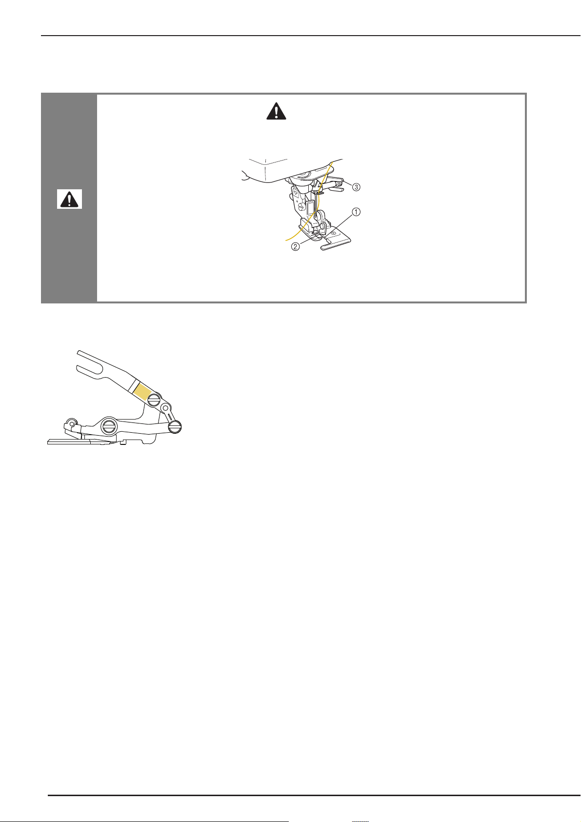
The following warning label is on the included side cutter. Be sure to observe the precaution.
• When using the side cutter, sew between low and mid-speed and do not touch the knives or
operation lever of the side cutter while sewing to avoid equipment damage or injury.
a Guide plate (lower knife)
b Upper knife
c Operation lever
Label location
iv
Page 7

IMPORTANT SAFETY INSTRUCTIONS
v
Page 8

OUTSTANDING FEATURES
Checking the Needle Location in
the Screen
Edge Sewing
You can check the needle drop position on the
screen of your machine, even if the needle has not
actually been lowered. Also, you can view the
location of the needle within the sewing area in
the screen.
See “Checking the Needle Location in the Screen”
on page 75.
Using the built-in camera, the width of the area
from the edge of the fabric to the stitching line can
be measured and set for edge sewing.
See “Edge Sewing” on page 138.
vi
Page 9
Using the Built-In Camera to
Note
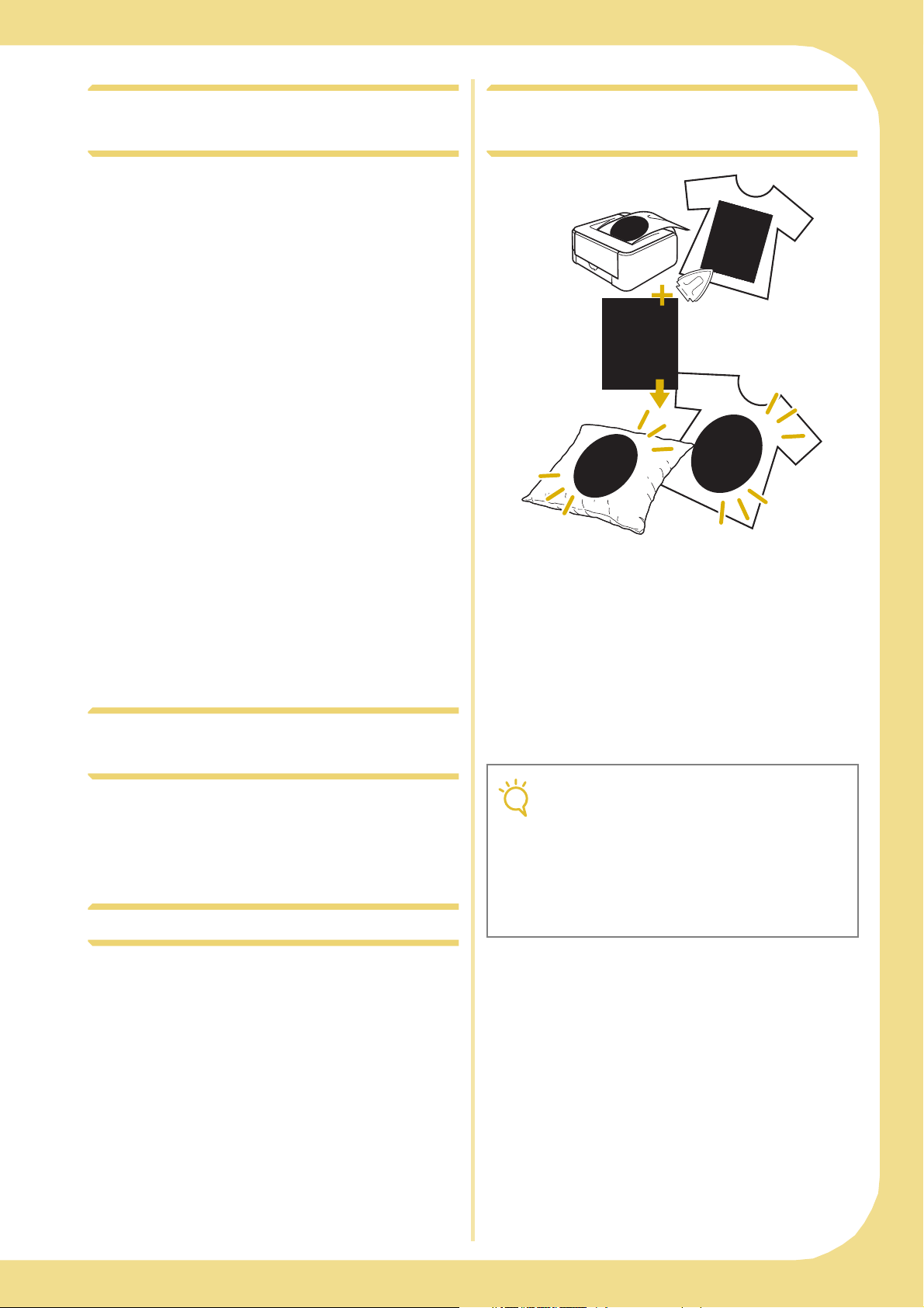
Print and Stitch (Combining the
Align the Embroidering Position
The embroidering position can easily be aligned
by using the machine’s built-in camera and the
enclosed embroidery positioning sticker.
See “Using the Built-In Camera to Align the
Embroidering Position” on page 205 and 300.
Uninterrupted Embroidering
(Using a Single Color)
Embroidery and Printing)
Completed embroidery patterns can be combined
with printed backgrounds that are built into this
machine.
Beautiful three-dimensional embroidered designs
can be created by ironing a background onto
fabric or printing it onto printable fabric, and then
embroider a design to compliment the
background.
See “PRINT AND STITCH (COMBINING
EMBROIDERY PATTERNS AND PRINTED
DESIGNS)” on page 215 and 304.
You can embroider a multi-color pattern with a single
color without stopping the machine while
embroidering.
See “Uninterrupted Embroidering (Using a Single
Color)” on page 293.
Duplicating a Pattern
You can duplicate a desired pattern with one touch.
See “Duplicating a Pattern” on page 288.
• Print the background and embroidery
position sheet in their original dimensions. If
an image is printed in a different size, the
sizes of the embroidery pattern and
background may not match. In addition, the
built-in camera cannot detect the
embroidery position mark. Make sure that
the print settings are correctly specified.
vii
Page 10

WHAT YOU CAN DO WITH THIS MACHINE
Getting Ready
To learn the operation of the principal parts and the
screens
Chapter 1
Page 11
Utility Stitches
Pre-programmed with more than 100 frequently used
stitches
Chapter 3
Page 77
Embroidery
Maximum 30 cm × 20 cm (approx. 12 × 8 inches) for
large embroidery designs
Sewing Basics
To learn how to prepare for sewing and basic sewing
operations
Chapter 2
Page 59
Character/Decorative
Stitches
The variety of stitches widen your creativity
Chapter 4
Page 145
Embroidery Edit
Designs can be combined, rotated or enlarged
Chapter 5
Page 181
Appendix
Caring for your machine and dealing with errors and
malfunctions
Chapter 7
Page 311
Chapter 6
Page 259
viii
Page 11
HOW TO USE THIS MANUAL
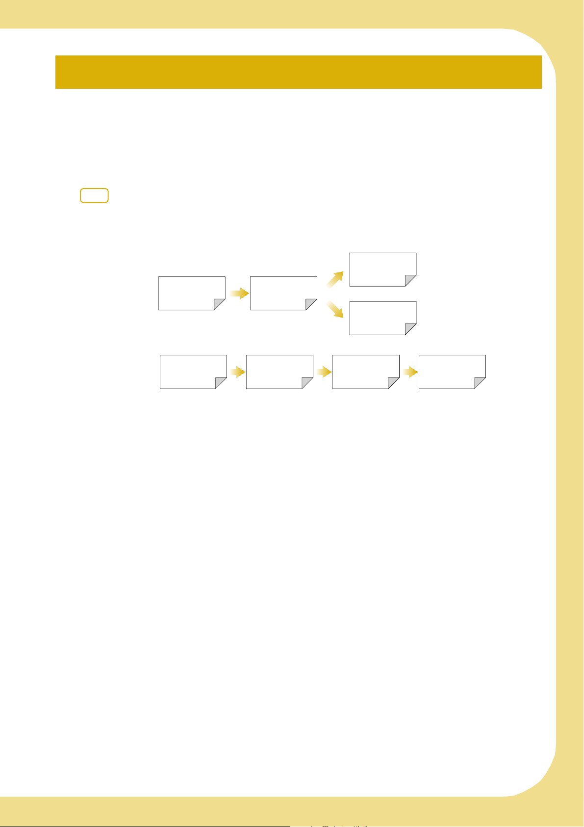
Chapter 1 and Chapter 2 explain your sewing machine’s basic operation procedures for someone who is
using the sewing machine for the first time. If you want to sew utility stitches or character/ decorative
stitches, read Chapter 1 and Chapter 2, then go on to Chapter 3 (Utility Stitches) or Chapter 4 (Character/
Decorative Stitches).
When you are ready to begin using the embroidery function after reading Chapter 1 and Chapter 2,
proceed to Chapter 5 (Embroidery). Once you understand the steps explained in Chapter 5, go on to
Chapter 6 (Embroidery Edit) for an explanation about the embroidery edit functions.
In the screens appearing in the step-by-step instructions, the parts referred to in the operations are marked
with . Compare the screen in the directions with the actual screen, and carry out the operation.
If, while using the machine, you experience something you do not understand, or there is a function you
would like to know more about, refer to the index at the back of the operation manual in conjunction
with the table of contents to find the section of the manual you should refer to.
Chapter 3
To sew utility stitches
To sew character or
decorative stitches
Chapter 1 Chapter 2
Chapter 4
To do machine
embroidery
Chapter 1 Chapter 2 Chapter 5 Chapter 6
ix
Page 12

CONTENTS
CONTENTS
INTRODUCTION ...................................................i
IMPORTANT SAFETY INSTRUCTIONS ..................i
OUTSTANDING FEATURES .................................vi
WHAT YOU CAN DO WITH THIS MACHINE ...viii
HOW TO USE THIS MANUAL .............................ix
NAMES OF MACHINE PARTS AND THEIR
FUNCTIONS...........................................................1
Machine..................................................................................1
Needle and Presser Foot Section .............................................2
Embroidery Unit......................................................................3
Operation Buttons...................................................................3
Using the Flat Bed Attachment................................................4
Using the Accessory Case........................................................4
Using the Embroidery Unit Carrying Case ...............................5
Included Accessories...............................................................5
Options...................................................................................8
Using the Spool Stand .............................................................9
Chapter 1 Getting Ready 11
TURNING THE MACHINE ON/OFF....................12
LCD SCREEN .......................................................14
USB Connectivity ..................................................................18
Using the Machine Setting Mode Key ...................................22
Using the Sewing Machine Help Key ...................................32
Using the Operation Guide Function.....................................33
Using the Sewing Guide Function .........................................34
Using the Pattern Explanation Function.................................35
LOWER THREADING ..........................................37
Winding the Bobbin ..............................................................37
Setting the Bobbin .................................................................43
Pulling Up the Bobbin Thread ...............................................45
UPPER THREADING............................................46
Upper Threading...................................................................46
Using the Twin Needle Mode................................................49
Using the Spool Stand ...........................................................52
Using Threads that Unwind Quickly .....................................53
CHANGING THE PRESSER FOOT .......................54
Removing the Presser Foot ....................................................54
Attaching the Presser Foot .....................................................54
Attaching the Walking Foot ...................................................55
CHANGING THE NEEDLE...................................56
About the Needle ..................................................................58
Fabric/Thread/Needle Combinations .....................................58
Chapter 2 Sewing Basics 59
SEWING ..............................................................60
Sewing a Stitch......................................................................60
Sewing Reinforcement Stitches..............................................62
Sewing Curves.......................................................................62
Changing Sewing Direction...................................................63
Sewing Heavyweight Fabrics.................................................63
Sewing Hook-and-Loop Fastener ...........................................64
Sewing Lightweight Fabrics ...................................................64
Sewing Stretch Fabrics...........................................................65
STITCH SETTINGS...............................................66
Setting the Stitch Width.........................................................66
Setting the Stitch Length ........................................................67
Setting the Thread Tension ....................................................67
USEFUL FUNCTIONS..........................................69
Automatic Reinforcement Stitching .......................................69
Automatic Thread Cutting .....................................................70
Using the Knee Lifter .............................................................71
Pivoting.................................................................................72
Automatic Fabric Sensor System
(Automatic Presser Foot Pressure)..........................................73
Needle Position – Stitch Placement .......................................74
Locking the Screen ............................................................... 74
Checking the Needle Location in the Screen......................... 75
Chapter 3 Utility Stitches 77
SELECTING UTILITY STITCHES .......................... 78
Selecting a Stitch .................................................................. 79
Saving Your Stitch Settings.................................................... 81
SEWING THE STITCHES ..................................... 83
Straight Stitches .................................................................... 83
Dart Seam............................................................................. 88
Gathering ............................................................................. 88
Flat Fell Seam ....................................................................... 89
Pintuck ................................................................................. 90
Zigzag Stitches...................................................................... 91
Elastic Zigzag Stitches........................................................... 93
Overcasting .......................................................................... 94
Quilting................................................................................ 99
Blind Hem Stitches............................................................. 111
Appliqué............................................................................. 113
Shelltuck Stitches................................................................ 114
Scallop Stitches................................................................... 115
Crazy Quilting.................................................................... 116
Smocking Stitches............................................................... 116
Fagoting.............................................................................. 117
Tape or Elastic Attaching .................................................... 117
Heirloom............................................................................ 119
One-step Buttonholes ......................................................... 121
Four-step Buttonholes......................................................... 125
Bar Tacks............................................................................ 129
Button Sewing .................................................................... 131
Eyelet.................................................................................. 133
Multi-directional Sewing (Straight Stitch and Zigzag Stitch).......134
Zipper Insertion.................................................................. 135
Edge Sewing ....................................................................... 138
Chapter 4 Character/Decorative Stitches 145
SELECTING STITCH PATTERNS ........................ 146
Selecting Decorative Stitch Patterns/7mm Decorative Stitch
Patterns/Satin Stitch Patterns/7mm Satin Stitch Patterns/
Cross Stitch/Utility Decorative Stitch Patterns ..................... 148
Alphabet Characters ........................................................... 148
SEWING STITCH PATTERNS ............................ 152
Sewing Attractive Finishes .................................................. 152
Basic Sewing ...................................................................... 152
Making Adjustments........................................................... 153
EDITING STITCH PATTERNS............................ 155
Changing the Size............................................................... 157
Changing the Length
(for 7mm Satin Stitch Patterns Only) ................................... 157
Creating a Vertical Mirror Image......................................... 157
Creating a Horizontal Mirror Image .................................... 158
Sewing a Pattern Continuously ........................................... 158
Changing Thread Density (for Satin Stitch Patterns Only)........158
Returning to the Beginning of the Pattern............................ 159
Checking the Image............................................................ 160
COMBINING STITCH PATTERNS..................... 162
Before Combining............................................................... 162
Combining Various Stitch Patterns...................................... 162
Combining Large and Small Stitch Patterns......................... 164
Combining Horizontal Mirror Image Stitch Patterns ............ 165
Combining Stitch Patterns of Different Length..................... 165
Making Step Stitch Patterns
(for 7mm Satin Stitch Patterns Only) ................................... 166
USING THE MEMORY FUNCTION .................. 169
Stitch Data Precautions....................................................... 169
Saving Stitch Patterns in the Machine’s Memory................. 171
Saving Stitch Patterns to USB Media ................................... 173
Saving Stitch Patterns in the Computer................................ 175
x
Page 13

CONTENTS
Retrieving Stitch Patterns from the Machine’s Memory........ 176
Recalling from USB Media.................................................. 177
Recalling from the Computer ..............................................178
Chapter 5 Embroidery 181
BEFORE EMBROIDERING .................................182
Embroidery Step by Step .....................................................182
Attaching Embroidery Foot “W”.......................................... 183
Attaching the Embroidery Unit............................................ 184
SELECTING PATTERNS......................................186
Selecting Embroidery Patterns/Baby Lock “Exclusives”/Greek
Alphabet Patterns/Floral Alphabet Patterns/Utility Embroidery
Patterns...............................................................................189
Selecting Alphabet Character Patterns.................................190
Selecting Frame Patterns ..................................................... 193
Selecting Patterns from Embroidery Cards........................... 194
Selecting Patterns from USB Media/Computer..................... 194
VIEWING THE SEWING SCREEN......................195
PREPARING THE FABRIC ..................................197
Attaching Iron-on Stabilizers (Backing) to the Fabric ........... 197
Hooping the Fabric in the Embroidery Frame ...................... 199
Embroidering Small Fabrics or Fabric Edges ........................ 202
ATTACHING THE EMBROIDERY FRAME..........203
CONFIRMING THE PATTERN POSITION.........205
Using the Built-In Camera
to Align the Embroidering Position...................................... 205
Checking the Pattern Position .............................................208
Previewing the Completed Pattern ......................................209
SEWING AN EMBROIDERY PATTERN ..............210
Sewing Attractive Finishes...................................................210
Using Prewound Bobbins.................................................... 211
Sewing Embroidery Patterns................................................ 212
Sewing Embroidery Patterns Which Use Appliqué ..............213
PRINT AND STITCH (COMBINING EMBROIDERY
PATTERNS AND PRINTED DESIGNS) ..............215
Selecting a Pattern ..............................................................216
Outputting the Background Image and Positioning Image ........ 217
Printing the Background and Embroidery Position Sheet ..... 219
Sewing Embroidery Patterns................................................ 220
ADJUSTMENTS DURING THE EMBROIDERY
PROCESS ............................................................221
If the Bobbin Runs Out of Thread........................................ 221
If the Thread Breaks During Sewing ....................................222
Restarting from the Beginning .............................................223
Resuming Embroidery After Turning Off the Power ............. 223
MAKING EMBROIDERY ADJUSTMENTS ..........225
Adjusting Thread Tension ................................................... 225
Adjusting the Alternate Bobbin Case
(with No Color on the Screw).............................................. 226
Using the Automatic Thread Cutting Function
(END COLOR TRIM)........................................................... 227
Using the Thread Trimming Function
(JUMP STITCH TRIM)..........................................................228
Adjusting the Embroidery Speed ......................................... 229
Changing the Thread Color Display ....................................229
Changing the Embroidery Frame Display ............................ 230
REVISING THE PATTERN ..................................232
Changing the Pattern Position .............................................232
Aligning the Pattern and the Needle....................................233
Changing the Size...............................................................234
Rotating the Pattern............................................................. 235
Creating a Horizontal Mirror Image .................................... 236
Changing the Density
(Alphabet Character and Frame Patterns Only).................... 237
Changing the Colors of Alphabet Character Patterns ........... 238
Embroidering Linked Characters .........................................239
Uninterrupted Embroidering (Using a Single Color).............241
USING THE MEMORY FUNCTION...................242
Embroidery Data Precautions.............................................. 242
Saving Embroidery Patterns in the Machine’s Memory ........ 244
Saving Embroidery Patterns to USB Media .......................... 247
Saving Embroidery Patterns in the Computer.......................248
Retrieving Patterns from the Machine’s Memory..................249
Recalling from USB Media ..................................................250
Recalling from the Computer...............................................252
EMBROIDERY APPLICATIONS ......................... 254
Using a Frame Pattern to Make an Appliqué (1)...................254
Using a Frame Pattern to Make an Appliqué (2)...................255
Sewing Split Embroidery Patterns ........................................257
Chapter 6 Embroidery Edit 259
EXPLANATION OF FUNCTIONS...................... 260
SELECTING PATTERNS TO EDIT ...................... 261
Selecting Embroidery Patterns/Baby Lock “Exclusives”/Greek
Alphabet Patterns/Floral Alphabet Patterns/Utility Embroidery
Patterns/Frame Patterns .......................................................262
Selecting Alphabet Character Patterns .................................262
EDITING PATTERNS ......................................... 265
Moving the Pattern ..............................................................267
Rotating the Pattern .............................................................267
Changing the Size of the Pattern..........................................268
Deleting the Pattern.............................................................269
Changing the Configuration of
Alphabet Character Patterns ................................................269
Changing Alphabet Character Spacing ................................270
Reducing Character Spacing................................................271
Separating Combined Character Patterns.............................272
Changing the Color of Each Alphabet Character
in a Pattern..........................................................................273
Embroidering Linked Characters ..........................................274
Changing the Thread Color .................................................276
Creating a Custom Thread Table .........................................277
Choosing a Color from the Custom Thread Table ................281
Designing Repeated Patterns ...............................................282
Duplicating a Pattern...........................................................288
After Editing ........................................................................288
COMBINING PATTERNS .................................. 289
Editing Combined Patterns ..................................................289
Sewing Combined Patterns..................................................292
VARIOUS EMBROIDERING FUNCTIONS ........ 293
Uninterrupted Embroidering (Using a Single Color) .............293
Basting Embroidery .............................................................293
Creating an Appliqué Piece.................................................294
Using the Built-In Camera to
Align the Embroidering Position..........................................300
USING THE MEMORY FUNCTION .................. 303
PRINT AND STITCH (COMBINING EMBROIDERY
PATTERNS AND PRINTED DESIGNS) .............. 304
Selecting a Pattern...............................................................305
Outputting the Background Image and Positioning Image ...305
Printing the Background and Embroidery Position Sheet......308
Sewing Embroidery Patterns ................................................309
Chapter 7 Appendix 311
CARE AND MAINTENANCE ............................. 312
Cleaning the LCD Screen ....................................................312
Cleaning the Machine Casing..............................................312
Cleaning the Race ...............................................................312
Cleaning the Bobbin Case ...................................................313
Cleaning the Cutter in the Bobbin Case Area .......................314
About the Maintenance Message .........................................315
ADJUSTING THE SCREEN ................................ 316
Touch Panel is Malfunctioning ............................................316
TROUBLESHOOTING ...................................... 317
ERROR MESSAGES............................................ 322
SPECIFICATIONS.............................................. 330
UPGRADING YOUR MACHINE’S SOFTWARE ........331
Upgrade Procedure Using USB Media.................................331
Upgrade Procedure Using Computer...................................332
STITCH SETTING CHART ................................. 335
INDEX............................................................... 344
1
2
3
4
5
6
7
xi
Page 14

CONTENTS
xii
Page 15
NAMES OF MACHINE PARTS AND THEIR FUNCTIONS
NAMES OF MACHINE PARTS AND THEIR FUNCTIONS
The names of the various parts of the sewing machine and their functions are described below. Before
using the sewing machine, carefully read these descriptions to learn the names of the machine parts.
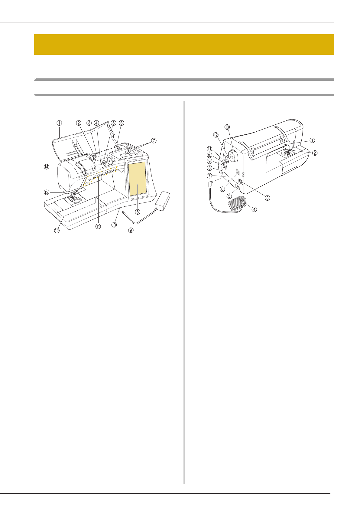
Machine
■ Front View
a Top cover
Open the top cover to thread the machine and wind the bobbin.
b Pre-tension disk
Pass the thread around the pre-tension disk when winding the
bobbin thread. (page 37)
c Thread guide for bobbin winding
Pass the thread through this thread guide when winding the
bobbin thread. (page 37)
d Spool pin
Place a spool of thread on the spool pin. (page 46)
e Spool cap
Use the spool cap to hold the spool of thread in place. (page 46)
f Supplemental spool pin
Use this spool pin to wind the bobbin thread, or to sew with the
twin needle. (page 37, 49)
g Bobbin winder
Use the bobbin winder when winding the bobbin. (page 37)
h LCD (liquid crystal display)
Settings for the selected stitch and error messages appear in
the LCD. (page 14)
i Knee lifter
Use the knee lifter to raise and lower the presser foot. (page 71)
j Knee lifter slot
Insert the knee lifter into the slot. (page 71)
k Operation buttons (6 buttons) and sewing speed
controller
Use these buttons and the slide to operate the sewing machine.
(page 3)
l Flat bed attachment with accessory compartment
Store presser feet and bobbins in the accessory compartment
of the flat bed attachment. When sewing cylindrical pieces,
remove the flat bed attachment. (page 4)
m Thread cutter
Pass the threads through the thread cutter to cut them. (page
48)
n Thread guide plate
Pass the thread around the thread guide plate when threading
upper thread. (page 46)
■ Right-side/Rear View
a Handle
Carry the sewing machine by its handle when transporting the
machine.
b Presser foot lever
Raise and lower the presser foot lever to raise and lower the
presser foot. (page 54)
c Main power switch
Use the main power switch to turn the sewing machine ON and
OFF. (page 12)
d Foot controller with retractable cord
Depress the foot controller to control the speed of the machine.
(page 61)
e Power cord receptacle
Insert the power cord into the machine receptacle. (page 12)
f Air vent
The air vent allows the air surrounding the motor to circulate. Do
not cover the air vent while the sewing machine is being used.
g Foot controller jack
Insert the foot controller plug into its jack on the machine. (page
61)
h Speaker
i USB port for computer
In order to import/export patterns between a computer and the
machine, plug the USB cable into the USB port. (page 18, 175,
248)
j USB port for mouse (page 18)
k Primary (top) USB port for media
In order to send patterns from/to USB media, plug the USB
media directly into the USB port. (page 173, 247)
l Touch pen holder
Use the touch pen holder to hold the touch pen when not in use.
m Handwheel
Rotate the handwheel toward you (counterclockwise) to raise
and lower the needle. The wheel should be turned toward the
front of the machine.
1
Page 16

NAMES OF MACHINE PARTS AND THEIR FUNCTIONS
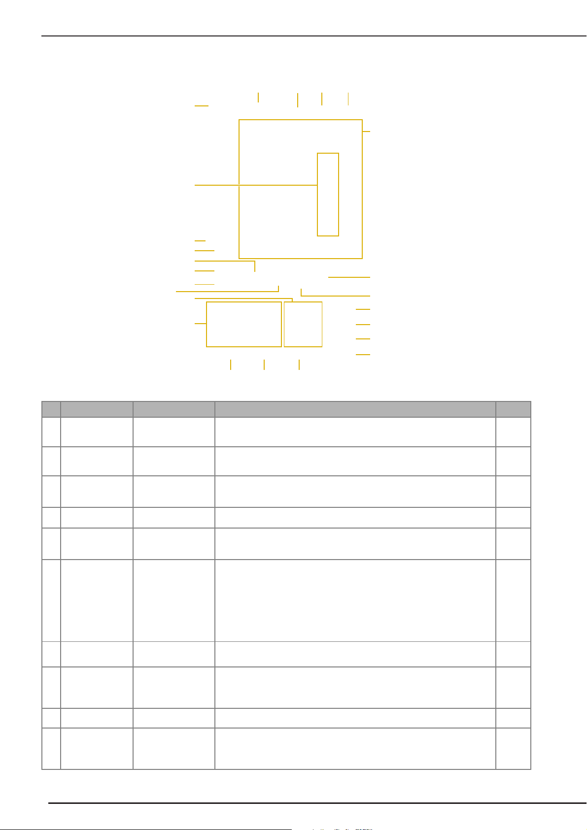
Needle and Presser Foot Section
a Buttonhole lever
The buttonhole lever is used with the one-step buttonhole foot
to create buttonholes. (page 121)
b Presser foot holder
The presser foot is attached to the presser foot holder. (page
54)
c Presser foot holder screw
Use the presser foot holder screw to hold the presser foot in
place. (page 55)
d Presser foot
The presser foot consistently applies pressure to the fabric as
sewing takes place. Attach the appropriate presser foot for the
selected stitch. (page 54)
e Feed dogs
The feed dogs feed the fabric in the sewing direction.
f Bobbin cover
Open the bobbin cover to set the bobbin. (page 43, 92)
g Needle plate cover
Remove the needle plate cover to clean the race. (page 86,
211)
h Needle plate
The needle plate is marked with guides to help sew straight
seams. (page 85)
i Needle bar thread guide
Pass the upper thread through the needle bar thread guide.
(page 46)
j Needle clamp screw
Use the needle clamp screw to hold the needle in place. (page
55)
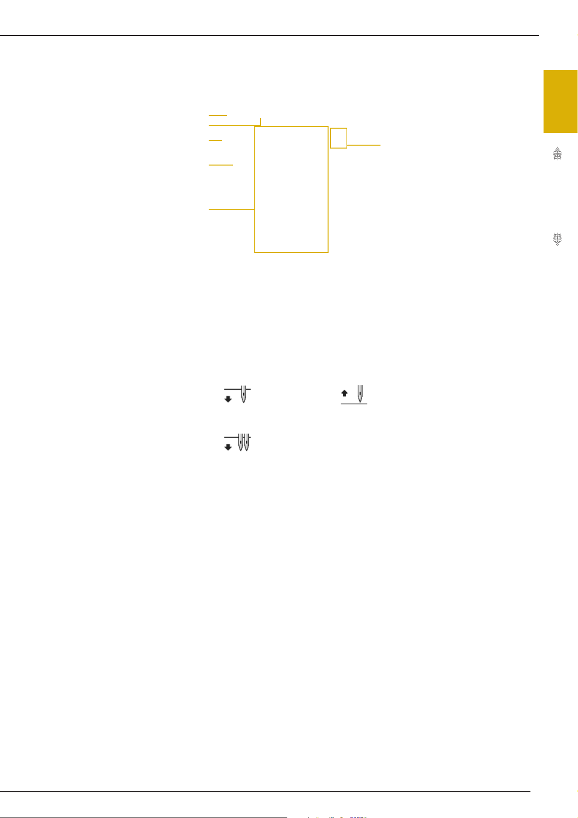
Measurements on the needle plate, bobbin cover
(with mark) and needle plate cover
The measurements on the bobbin cover are
references for patterns with a middle (center)
needle position. The measurements on the needle
plate and the needle plate cover are references for
stitches with a left needle position.
a For stitches with a middle (center) needle position
b For stitches with a left needle position
c Left needle position on the needle plate <inch>
d Left needle position on the needle plate <cm>
e Middle (center) needle position on the bobbin cover
(with mark) <inch>
f Left needle position on the needle plate cover <inch>
2
Page 17
NAMES OF MACHINE PARTS AND THEIR FUNCTIONS
CAUTION
CAUTION
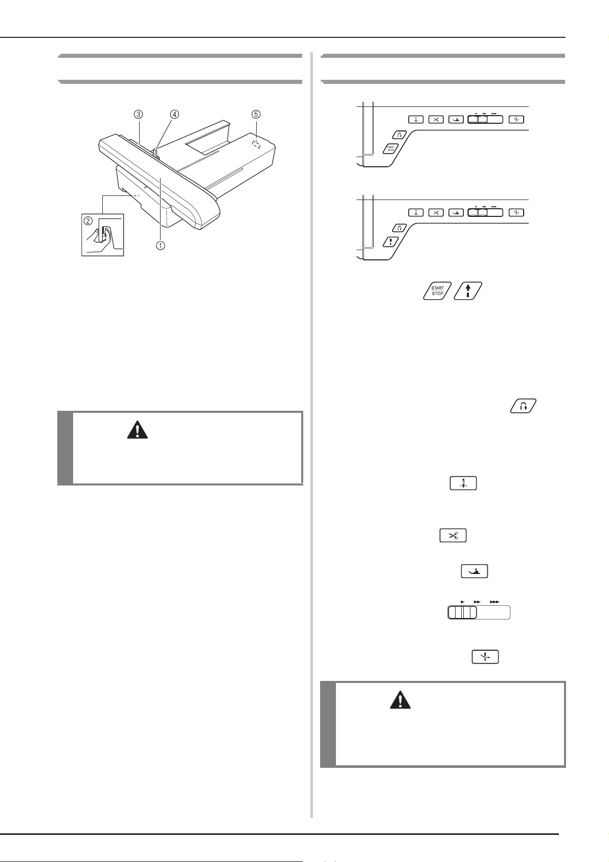
Embroidery Unit
a Carriage
The carriage moves the embroidery frame automatically when
embroidering. (page 184)
b Release button (located under the embroidery unit)
Press the release button to remove the embroidery unit. (page
185)
c Embroidery frame holder
Insert the embroidery frame into the embroidery frame holder to
hold the frame in place. (page 203)
d Frame-securing lever
Press the frame-securing lever down to secure the embroidery
frame. (page 203)
e Embroidery unit connection
Insert the embroidery unit connection into the connection port
when attaching the embroidery unit. (page 184)
• After the embroidery frame is set in the frame
holder, be sure the frame-securing lever is
correctly lowered.
Operation Buttons
a “Start/Stop” button
Press this button and the machine will sew a few stitches at a
slow speed and then begin sewing at the speed set by the
sewing speed controller. Press the button again to stop the
machine. Hold the button in to sew at the machine’s slowest
speed. The button changes color according to the machine’s
operation mode.
Green: The machine is ready to sew or is sewing.
Red: The machine cannot sew.
b “Reverse/Reinforcement Stitch” button
Use this button to sew reinforcement stitches at the beginning
and end of sewing. Press this button, and the machine sews 3
stitches in the same spot and stops automatically. For straight
and zigzag stitch patterns that take reverse stitches, the
machine will sew reverse stitches at low speed only while
holding down the “Reverse/Reinforcement Stitch” button (the
stitches are sewn in the opposite direction).
c “Needle Position” button
Use this button when changing sewing direction or for detailed
sewing in small areas. Press this button to raise or lower the
needle position. With this button, you can lower and raise the
needle to sew a single stitch.
d “Thread Cutter” button
Press this button after sewing to automatically trim the excess
thread.
e “Presser Foot Lifter” button
Press this button to lower the presser foot and apply pressure to
the fabric. Press this button again to raise the presser foot.
f Sewing Speed controller
Use this controller to adjust the sewing speed. Move the slide to
the left to sew at slower speeds. Move the slide to the right to
sew at higher speeds. Beginners should sew at a slow speed.
g “Automatic Threading” button
Use this button to automatically thread the needle.
• Do not press the thread cutter button after the
threads have been cut. The needle may break
and threads may become tangled, or damage
to the machine may occur.
3
Page 18
NAMES OF MACHINE PARTS AND THEIR FUNCTIONS
a
b
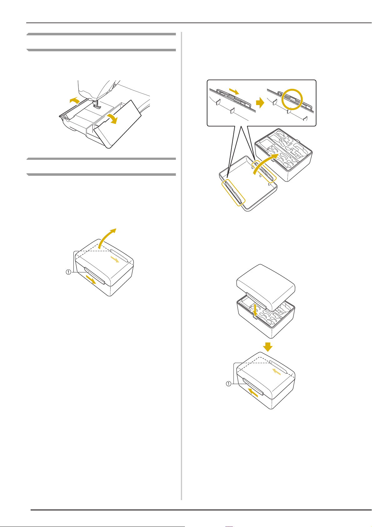
Using the Flat Bed Attachment
Pull the top of the flat bed attachment to open the
accessory compartment.
Using the Accessory Case
■ Opening the Accessory Case
Fully slide the bar on each side of the accessory
case, and then lift off the lid to open the case.
The case can only be opened or locked correctly if
both bars are slid in the same direction.
■ Closing the Accessory Case
Fully slide the bar on each side of the
accessory case lid to align the notches in
the lid with the notches in the bars.
Place the lid on top of the case so that the
notches in the lid align with the tabs on the
case, and then slide the bar on each side
back to the center of the accessory case.
a Bars
a Bars
4
Page 19
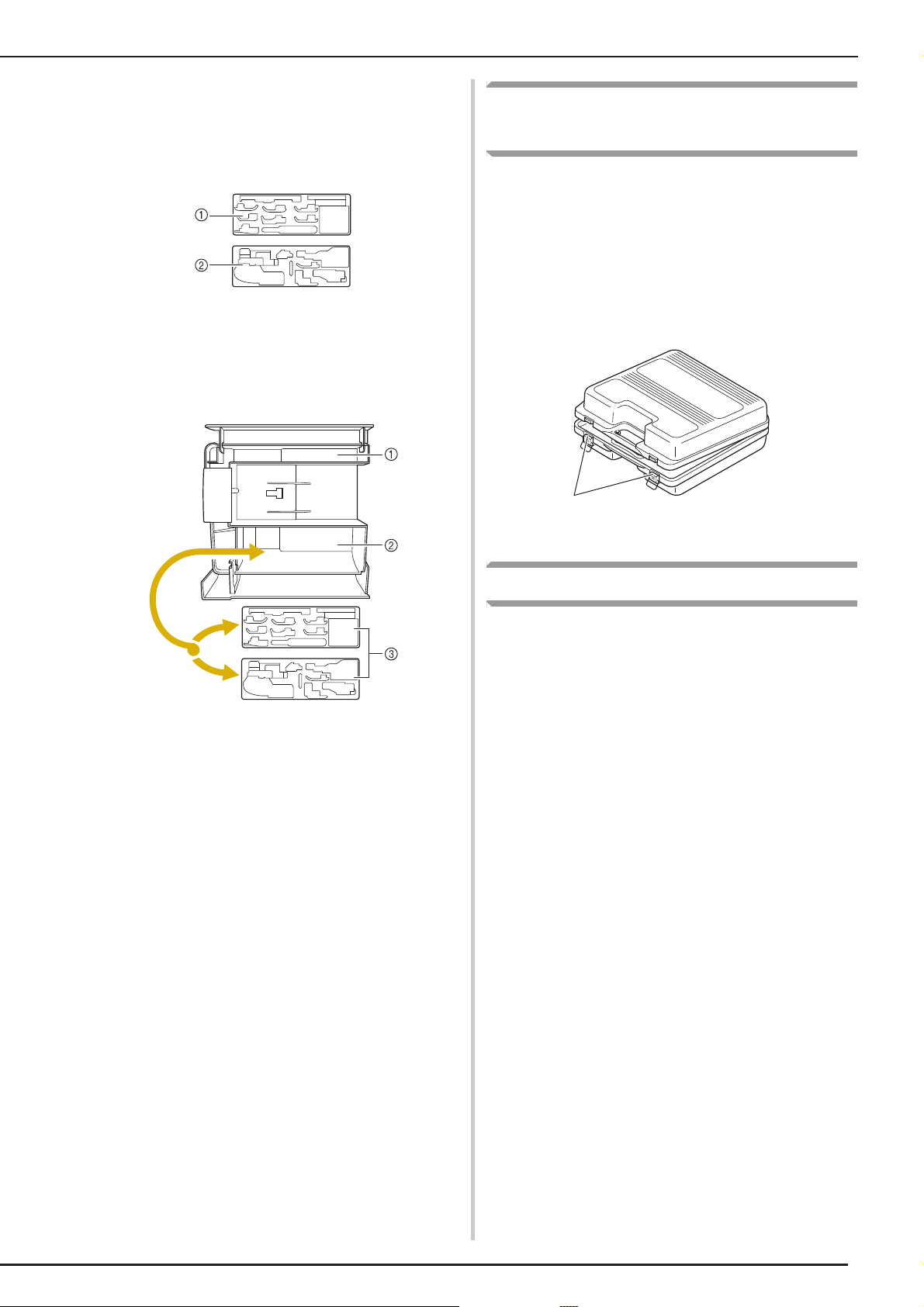
■ Using the Accessory Trays
a
Two presser foot storage trays are stored in the
included accessory case. One is for presser feet for
utility sewing, and the other is for presser feet for
embroidery and machine quilting.
a For presser feet for utility sewing
b For presser feet for embroidery and machine
quilting
For your convenience, a presser foot storage tray
can be stored in the accessory compartment of the
flat bed attachment.
NAMES OF MACHINE PARTS AND THEIR FUNCTIONS
Using the Embroidery Unit
Carrying Case
Included accessories 46-49 are contained in the
embroidery unit carrying case. To open the
embroidery unit carrying case, raise each lock and
move the latches out of position. To re-hook the
latches and securely close the case, position the
latch on the catch of the unit lid and lower the
lock till it snaps.
a Storage space of the flat bed attachment
b Presser foot storage space of the flat bed
attachment
c Presser foot storage trays
a Latches
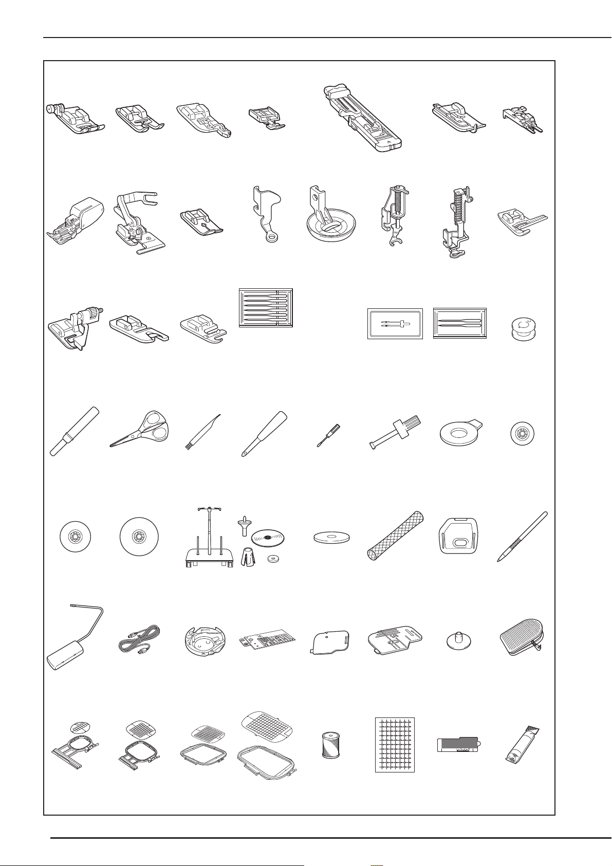
Included Accessories
See table on the next page about included
accessories.
5
Page 20
NAMES OF MACHINE PARTS AND THEIR FUNCTIONS
75/11 2 needles
90/14 2 needles
90/14 2 needles:
Ball point needle (gold colored)
12345 67
8 9 101112131415
* 17* 18*
16
23 24 25 26 27 28 29 30
31 32 33 34 35 36 37
19 20 21 22
2.0/11 needle
75/11 2needles
38 39 40 41 42 43 44 45
** 47** 48** 49**
46
*See Additional Accessories Guide for presser foot instruction.
**Included Accessories 46-49 are contained in the embroidery unit carrying case.
6
50 51 52 53
Page 21
NAMES OF MACHINE PARTS AND THEIR FUNCTIONS
Memo
54 55 56 57 58 59 60 61
62 63
No. Part Name Part Code
1 Zigzag foot “J” (on machine) XC3021-051
2 Monogramming foot “N” X53840-351
3 Overcasting foot “G” XC3098-051
4 Zipper foot “I” X59370-051
5 Buttonhole foot “A” X57789-151
6 Blind stitch foot “R” X56409-051
7 Button fitting foot “M” 130489-001
8 Walking foot XE1986-001
9 Side cutter foot XC3198-001
10 Straight stitch foot XD0826-051
11 Free motion quilting foot “C” XE0765-001
12 Free motion echo quilting foot
“E”
13 Free motion open toe quilting
foot “O”
14 Embroidery foot “W” XC8156-651
15 Vertical stitch alignment foot
“V”
16
Blind stitch foot (with guide)
17
Narrow hemmer foot
18
Cording foot (3 cord guide)
19 Needle set XE4962-001
20 Twin needle XE4963-001
21 Ball point needle set XD0705-051
22 Bobbin × 10
(One is on machine.)
23 Seam ripper X54243-001
24 Scissors 184783-051
25 Cleaning brush X59476-051
26 Eyelet punch 135793-001
27 Screwdriver (small) X55468-051
28 Screwdriver (large) X55467-051
29 Disc-shaped screwdriver XC1074-051
30 Spool cap (small) 130013-154
31 Spool cap (medium) × 2
(One is on machine.)
32 Spool cap (large) 130012-054
33 Spool stand See page 9
34 Spool felt X57045-051
35 Spool net × 2 XA5523-050
36 Embroidery needle plate
cover
37 Touch pen (stylus) XA9940-051
38 Knee lifter X4713-001
39 USB cable XD0745-051
*
*
*
XE0766-001
XE0767-001
XE0005-001
XA0059-001
XE0754-001
XA6871-001
X52860-150
X55260-153
XA9939-051
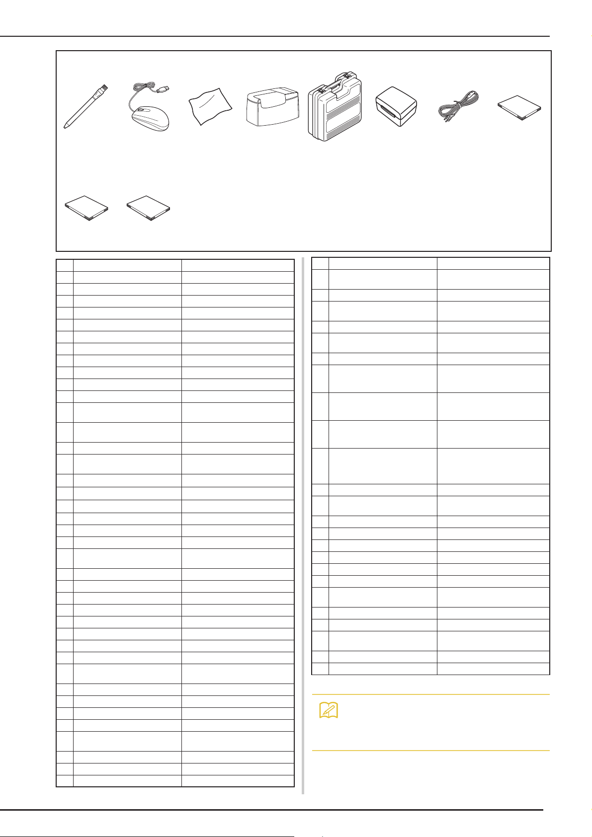
No. Part Name Part Code
40 Alternate bobbin case
(no color)
41 Straight stitch needle plate XE4908-001
42 Cord guide bobbin cover
(with single hole)
43 Bobbin cover (with mark) XE0756-001
44 Bobbin center pin and user
manual
45 Foot controller XC8028-051
46 Embroidery frame set (small)
H 2 cm × W 6 cm
(H 1 inch × W 2-1/2 inches)
47 Embroidery frame set
(medium) H 10 cm × W 10 cm
(H 4 inches × W 4 inches)
48 Embroidery frame set (quilt)
H 20 cm × W 20 cm
(H 8 inches × W 8 inches)
49 Embroidery frame set
(extra large)
H 30 cm × W 20 cm
(H 12 inches × W 8 inches)
50 Embroidery bobbin thread BBT-W
51 Embroidery positioning
stickers × 3
52 Edge sewing sheet × 6 XE5500-001
53 Stabilizer material BM3:XE0806-001
54 Chalk pencil 184944-001
55 USB mouse XE4904-001
56 LCD cleaning cloth XE5023-001
57 Soft cover XE5112-001
58 Embroidery unit carrying
case
59 Accessory case XE5073-001
60 Power cord XC6052-051
61 Instruction and reference
guide
62 Quick reference guide XE5022-001
63 Additional accessories guide XE5470-001
XC8167-451
XC8449-051
XD0836-051
EF73:Frame
EF77:Embroidery sheet
EF74:Frame
EF78:Embroidery sheet
EF91:Frame
EF93:Embroidery sheet
EF92:Frame
EF94:Embroidery sheet
XE4912-001
XE3803-001
XE5021-001
*See Additional Accessories Guide for presser foot instruction.
• Foot controller: Model S
This foot controller can be used on the
machine model:BLSO.
7
Page 22
NAMES OF MACHINE PARTS AND THEIR FUNCTIONS
Memo
Memo
Note
• Always use accessories recommended for
this machine.
• The screw for the presser foot holder is
available through your authorized retailer
(Part code XA4813-051).
• Included accessories 39, 45, 61, 62 and 63
can be stored in the machine’s soft cover
case.
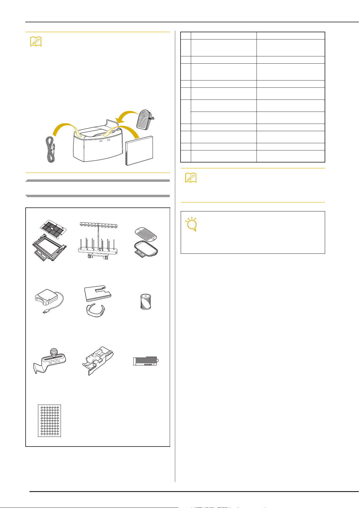
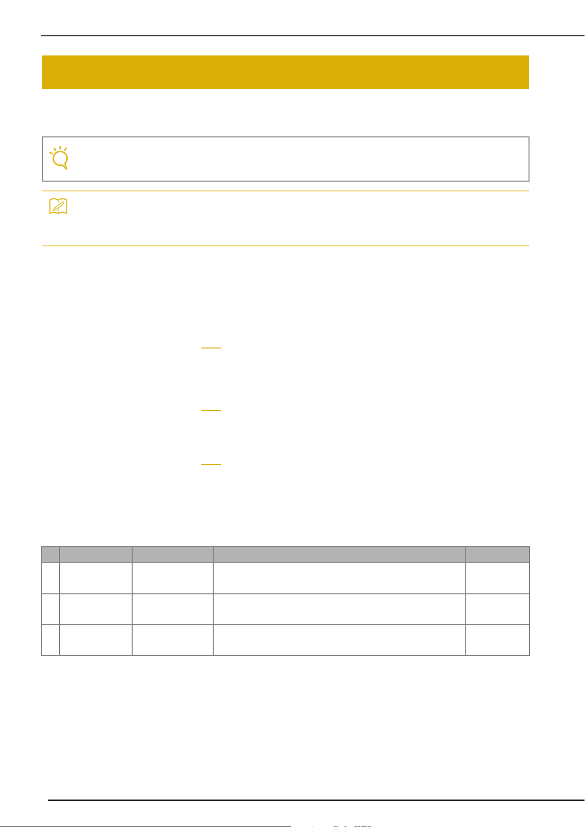
Options
No. Part Name Part Code
1 Border embroidery frame
H 18 cm × W 10 cm
(H 7 inches × W 4 inches)
2 10 spool stand BLSO-TS
3 Embroidery frame set (large)
H 18 cm × W 13 cm
(H 7 inches × W 5 inches)
4 Embroidery card Reader BLECR
5 Extension Table and free
motion grip
6 Embroidery bobbin
thread(white)
Embroidery bobbin
thread(black)
7 Seam guide BLG-SG
8 1/4 inch piecing foot with
guide
9 Edge sewing sheet × 5 BLSO-ESS
10 Embroidery positioning
stickers × 6
BLSO-BF
EF75:Frame
EF79:Embroidery sheet
BLSO-ET
BBT-W
BBT-B
ESG-QGF
BLSO-EPS
• All specifications are correct at the time of
printing. Please be aware that some specifications may change without notice.
123
456
789
• Embroidery cards purchased in foreign
countries may not work with your machine.
• Visit your nearest authorized retailer for a
complete listing of optional accessories.
8
10
Page 23
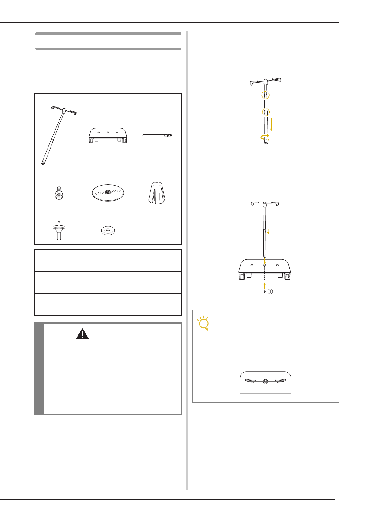
Using the Spool Stand
a
b
CAUTION
Note
The included spool stand is useful when using
thread spools with a large diameter (cross-wound
thread). The spool stand can hold two spools of
thread.
123
456
NAMES OF MACHINE PARTS AND THEIR FUNCTIONS
■ How to assemble the spool stand
Fully extend the telescopic thread guide
shaft, and then rotate the shaft until the two
internal stoppers click into place.
Insert the telescopic thread guide into the
round hole at the center of the spool
support, and then use a screwdriver to
securely tighten the screw (a) from the
reverse side.
78
No. Part Name Part Code
1 Telescopic thread guide XE0766-001
2 Spool support XE4958-001
3 Spool pin × 2 XA6313-051
4 Screw and washer XC7568-051
5 Spool cap (XL) × 2 XE0779-001
6 Spool holders × 2 XA0679-050
7 Spool cap base × 2 XE0780-001
8 Spool felt × 2 XC7134-051
• Do not lift the handle of the machine while the
spool stand is installed.
• Do not push or pull the telescopic thread
guide or spool pins with extreme force,
otherwise damage may result.
• Do not place any object other than spools of
thread on the spool support.
• Do not try to wind thread on the bobbin while
sewing using the spool stand.
a Screw
• Make sure that the stoppers on the telescopic thread guide shaft are firmly in place
and that the top of the thread guide is
directly above the spool pins. In addition,
check that the shaft is securely tightened in
the spool support.
9
Page 24
NAMES OF MACHINE PARTS AND THEIR FUNCTIONS
c
d
e
a
b
Memo
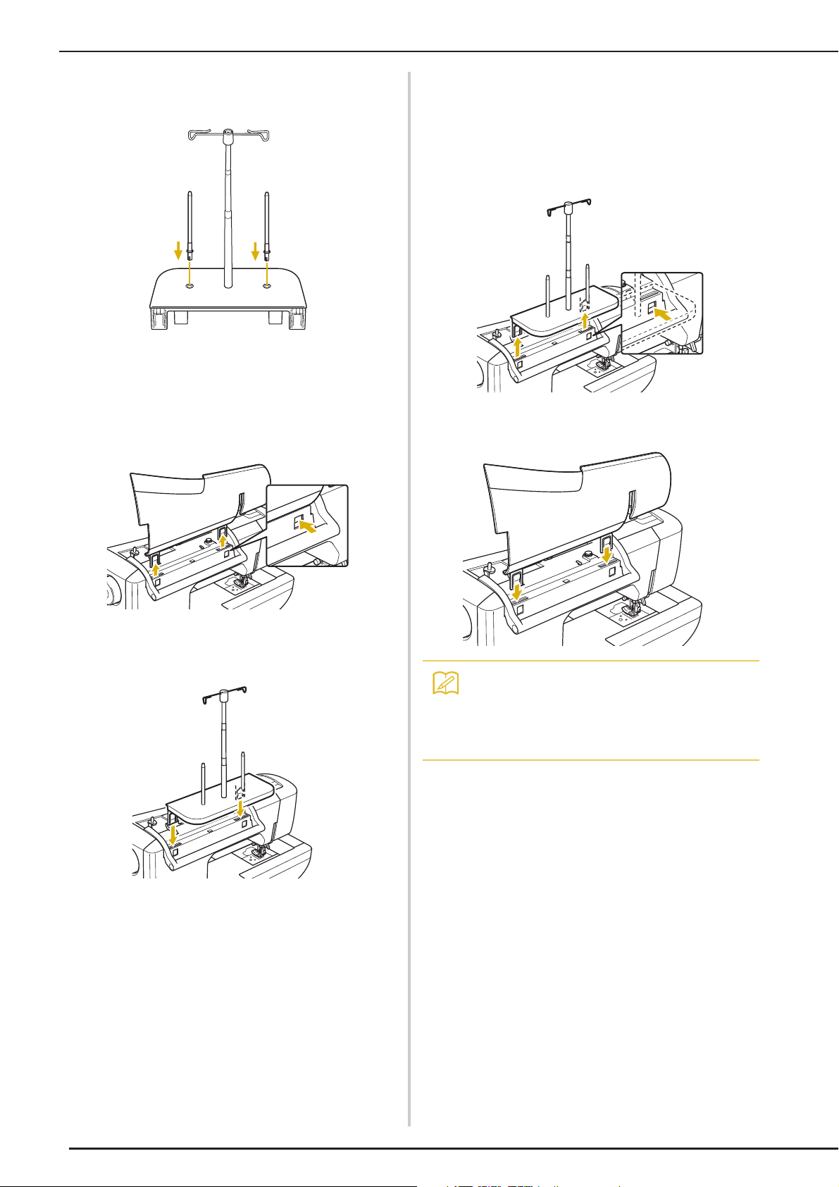
Firmly insert the two spool pins into the two
holes in the spool support.
Open the upper cover of the machine. From
the back of the machine, press in the upper
cover latches (one on each side), and then
pull the upper cover up to remove it from
the machine.
■ How to remove
From the back of the machine, press in the
spool stand latches (one on each side), and
then pull the spool stand up to remove it
from the machine.
Attach the upper cover to the machine.
Insert the spool stand onto the notches of
the machine.
• See page 41 about the bobbin winding using
the spool stand.
• See page 52 about the upper threading
using the spool stand.
10
Page 25

Chapter 1
Getting Ready
TURNING THE MACHINE ON/OFF...............12
LCD SCREEN...................................................14
■ Home Page Screen ................................................................... 14
■ Utility Stitch LCD Screen ......................................................... 15
■ Key Functions ...........................................................................16
USB Connectivity.............................................................. 18
■ Using USB Media or Embroidery Card Reader/
USB Card Writer Module*........................................................ 18
■ Connecting the Machine to the Computer ............................... 19
■ Using a USB Mouse ..................................................................19
■ Clicking a Key ..........................................................................20
■ Changing Pages ........................................................................20
Using the Machine Setting Mode Key ............................... 22
■ Changing the Pointer Shape When a USB Mouse Is Used ........25
■ Changing the Screen Saver Image ............................................25
■ Selecting the Initial Screen Display ..........................................28
■ Choosing the Display Language................................................ 29
■ Changing the Background Colors
of the Embroidery Patterns.......................................................30
Using the Sewing Machine Help Key ................................ 32
Using the Operation Guide Function................................ 33
Using the Sewing Guide Function..................................... 34
Using the Pattern Explanation Function ............................ 35
LOWER THREADING .....................................37
Winding the Bobbin .......................................................... 37
■ Using the Supplemental Spool Pin............................................37
■ Using the Spool Pin ..................................................................40
■ Using the Spool Stand ..............................................................41
■ Untangling Thread from Beneath the Bobbin Winder Seat.......42
Setting the Bobbin ............................................................ 43
Pulling Up the Bobbin Thread........................................... 45
UPPER THREADING.......................................46
Upper Threading............................................................... 46
Using the Twin Needle Mode ........................................... 49
Using the Spool Stand ....................................................... 52
■ Using the Spool Stand ..............................................................52
Using Threads that Unwind Quickly ................................. 53
■ Using the Spool Net .................................................................53
CHANGING THE PRESSER FOOT ..................54
Removing the Presser Foot................................................ 54
Attaching the Presser Foot ................................................ 54
Attaching the Walking Foot .............................................. 55
CHANGING THE NEEDLE..............................56
About the Needle.............................................................. 58
Fabric/Thread/Needle Combinations................................ 58
Page 26
TURNING THE MACHINE ON/OFF
WARNING
CAUTION
TURNING THE MACHINE ON/OFF
• Use only regular household electricity for the power source. Using other power sources may result in fire,
electric shock, or damage to the machine.
• Make sure that the plugs on the power cord are firmly inserted into the electrical outlet and the power
cord receptacle on the machine.
• Do not insert the plug on the power cord into an electrical outlet that is in poor condition.
• Turn the main power to OFF and remove the plug in the following circumstances:
When you are away from the machine
After using the machine
When the power fails during use
When the machine does not operate correctly due to a bad connection or a disconnection
During electrical storms
• Use only the power cord included with this machine.
• Do not use extension cords or multi-plug adapters with many other appliances plugged in to them. Fire or
electric shock may result.
• Do not touch the plug with wet hands. Electric shock may result.
• When unplugging the machine, always turn the main power to OFF first. Always grasp the plug to remove
it from the outlet. Pulling on the cord may damage the cord, or lead to fire or electric shock.
• Do not allow the power cord to be cut, damaged, modified, forcefully bent, pulled, twisted, or bundled.
Do not place heavy objects on the cord. Do not subject the cord to heat. These things may damage the
cord, or cause fire or electric shock. If the cord or plug is damaged, take the machine to your authorized
retailer for repairs before continuing use.
• Unplug the power cord if the machine is not to be used for a long period of time. Otherwise, a fire may
result.
• When leaving the machine unattended, either the main switch of the machine should be turned to OFF or
the plug must be removed from the socket-outlet.
• When servicing the machine or when removing covers, the machine must be unplugged.
• For U.S.A only
This appliance has a polarized plug (one blade wider than the other). To reduce the risk of electrical
shock, this plug is intended to fit in a polarized outlet only one way.
If the plug does not fit fully in the outlet, reverse the plug. If it still does not fit, contact a qualified
electrician to install the proper outlet. Do not modify the plug in any way.
12
Page 27
a
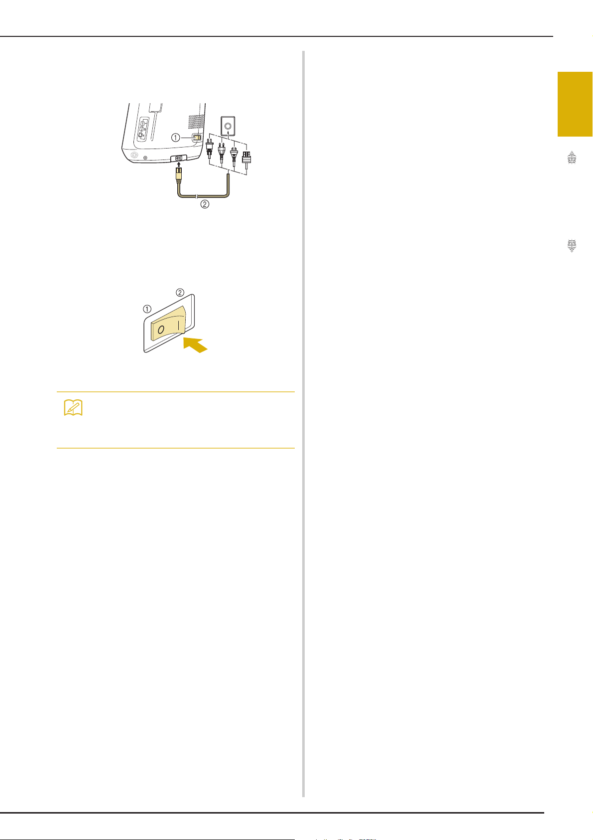
Insert the power supply cord into the power
b
c
Memo
cord receptacle, then insert the plug into a
wall outlet.
a Main power switch
b Power supply cord
Turn the main power switch to “I” to turn
on the machine.
TURNING THE MACHINE ON/OFF
1
Getting Ready
a OFF
b ON
• When the machine is turned on, the needle
and the feed dogs will make sound when
they move; this is not a malfunction.
Turn the main power switch to “O” to turn
off the machine.
13
Page 28
LCD SCREEN
Note
Memo
LCD SCREEN
When the machine is turned on, the opening movie is played. Touch anywhere on the screen for the
home page screen to be displayed. Touch the LCD screen or a key with your finger or the included touch
pen to select a machine function.
• When the straight stitch needle plate is on the machine, the needle will automatically move to the middle position.
• Only touch the screen with your finger or the included touch pen. Do not use a sharp pencil, screwdriver, or other hard or sharp object. It is not necessary to press hard on the screen. Pressing too hard
or using a sharp object may damage the screen.
■ Home Page Screen
a
b
c
No. Display Key Name Explanation Page
a Sewing key Press this key to sew utility stitches or character or decorative stitch
patterns.
b Embroidery key Attach the embroidery unit and press this key to embroider patterns. 182
c Embroidery Edit key Press this key to combine embroidery patterns. With the embroidery
edit functions, you can also create original embroidery patterns or frame
patterns.
See the “Key
Functions” table.
16
260
14
Page 29
LCD SCREEN
a
b
c
d
e
f
■ Utility Stitch LCD Screen
Press a key with your finger to select the stitch pattern, to select a machine function, or to select an
operation indicated on the key.
1
Getting Ready
a Shows single or twin needle mode setting, and the needle stop position.
Single needle/down position Single needle/up position
Twin needle/down position Twin needle/up position
b Shows the name and code number of the selected stitch.
c Shows the presser foot code. Attach the presser foot indicated in this display before sewing.
d Shows a preview of the selected stitch.
When shown at 100%, the stitch appears in the screen at nearly its actual size.
e Shows the stitch patterns.
f Shows additional pages that can be displayed (Illustration shows page 1 of 2.).
* All key functions of the LCD are explained in the “Key Functions” table on the following page.
15
Page 30
LCD SCREEN
a
b e
f
g
h
i
j
k
l
mno
v
q
s
p
u
r
t
cxd
w
■ Key Functions
No. Display Key Name Explanation Page
a Utility stitch key Press this key to select a straight stitch, zigzag stitch, buttonhole, blind hem
b Character/Decorative
c Screen lock key Press this key to lock the screen.When the screen is locked, the various
d Image key Press this key to display an enlarged image of the selected stitch pattern. 80
e Home page screen
f Stitch selection
g Edge sewing key Using the built-in camera, press this key to measure the width of the area from
h Needle mode
i Retrieve key Press this key to retrieve a saved pattern. 82
j Manual memory key Change the stitch pattern settings (zigzag width and stitch length, thread
stitch key
key
display
selection key (single/
double)
stitch, or other stitches commonly used in garment construction.
Press this key to select character or decorative stitch patterns. 146
settings, such as the stitch width and stitch length, are locked and cannot be
changed. Press this key again to unlock the settings.
Press this key anytime it is displayed to return to the home page screen and
select a different category - “Utility and Decorative Stitches”, “Embroidery” or
“Embroidery edit”.
Press the key for the pattern you want to sew. Use
to change to different stitch groups.
the edge of the fabric to the stitch and set the camera for edge sewing.
Press this key to select twin needle sewing mode. The sewing mode changes
between single needle mode and twin needle mode each time you press the
key. If the key display is light gray, the selected stitch pattern cannot be sewn in
the twin needle mode.
tension, automatic thread cutting or automatic reinforcement stitching, etc.),
then save them by pressing this key. Five sets of settings can be saved for a
single stitch pattern.
16
79
74
14
79
138
49
81
Page 31

LCD SCREEN
No. Display Key Name Explanation Page
k Reset key Press this key to return the selected stitch pattern saved settings to the default
l Presser foot/Needle
exchange key
m Sewing machine help
key
n Camera view key Touch this key to check the needle location as it is shown on the screen through
o Machine setting mode
key
p Stitch width and stitch
length key
settings.
Press this key before changing the needle, the presser foot, etc. This key locks
all key and button functions to prevent operation of the machine.
Press this key to see explanations on how to use the machine. 32
the built in camera.
Press this key to change the needle stop position, change the volume of
operation beep, adjust the pattern or screen, and change other machine
settings.
Shows the zigzag width and stitch length settings of the currently selected stitch
pattern. You can use the plus and minus keys to adjust the zigzag width and
stitch length settings.
66-67
54-57
75
22
66
1
Getting Ready
q Thread tension key Shows the automatic thread tension setting of the currently selected stitch
pattern. You can use the plus and minus keys to change the thread tension
settings.
r Mirror image key Press this key to create a mirror image of the selected stitch pattern. If the key
s Automatic thread
cutting key
t Automatic
reinforcement stitch
key
u Free motion mode key Press this key to enter free motion sewing mode.
v Pivot key Press this key to select the pivot setting. When the pivot setting is selected,
w Pattern display size Shows the approximate size of the pattern selected.
x Scroll key
display is light gray, a mirror image of the selected stitch pattern cannot be
sewn.
Press this key to set the automatic thread cutting function. Set the automatic
thread cutting function before sewing to have the machine automatically sew
reinforcement stitches at the beginning and end of sewing (depending on the
pattern, the machine may sew reverse stitches) and trim the threads after
sewing.
Press this key to use the automatic reinforcement stitching (reverse stitching)
setting. If you select this setting before sewing, the machine will automatically
sew reinforcement stitches at the beginning and end of sewing (depending on
the pattern, the machine may sew reverse stitches).
The presser foot is raised to an appropriate height and the feed dog is lowered
for free motion quilting.
stopping the machine lowers the needle and slightly raises the presser foot
automatically. In addition, when sewing is restarted, the presser foot is
automatically lowered.
• If this key appears as , the pivot function cannot be used.
• Be sure the needle position on page 23 of Machine Settings is set to the
down position.
: Nearly the same size as the sewn pattern
: 1/2 the size of the sewn pattern
: 1/4 the size of the sewn pattern
* The actual size of the sewn pattern may differ depending on the type of
fabric and thread that is used.
Press or , to move one page at a time, or touch anywhere on the bar
to jump ahead for additional pages of stitches.
67
79
69
69
105
72
79
17
Page 32

LCD SCREEN
Note
Note
Memo
USB Connectivity
You can perform many functions using the USB
ports on the machine. Connect the appropriate
devices according to the feature of each ports.
a Primary (top) USB port
b Embroidery card Reader/USB card writer module*
a Primary (top) USB port for media or card Reader/
USB card writer module* (USB2.0)
* If you have purchased the Palette Ver5 or later,
Palette Petite or Palette PTS, you can plug the
included USB card writer module into the machine
as an embroidery card reader, and recall patterns.
b USB port for mouse (USB1.1)
c USB port for computer
• The processing speed may vary by port
selection and quantity of data.
• Do not insert anything other than USB
media into the USB media port. Otherwise,
the USB media drive may be damaged.
■ Using USB Media or Embroidery
Card Reader/USB Card Writer
Module*
When sending or reading patterns using the USB
media or the embroidery card Reader/USB card
writer module*, connect the device to the primary
(top) USB port.
The primary (top) USB port processes the data faster
than the other ports.
* If you have purchased the Palette Ver5 or later,
Palette Petite or Palette PTS, you can plug the
included USB card writer module into the machine
as an embroidery card reader, and recall patterns.
• Two USB media cannot be used with this
machine at the same time. If two USB media
are inserted, only the USB media inserted
first is detected.
• Use only an embroidery card reader
designed for this machine. Using an
unauthorized embroidery card reader may
cause your machine to operate incorrectly.
• Embroidery patterns cannot be saved from
the machine to an embroidery card inserted
into a connected USB card writer module.
• USB media is widely used, however some
USB media may not be usable with this
machine. Please visit our website for more
details.
• Depending on the type of USB media being
used, either directly plug the USB device
into the machine’s USB port or plug the USB
media Reader/Writer into the machine’s
USB port.
• You can plug the optional embroidery card
Reader/USB card writer module* into the
primary (top) or center port, when the mouse
is not connected.
• You can plug a USB media into the center
port, but the primary (top) USB port
processes the data faster. It is
recommended to use the primary (top) USB
port.
18
a Primary (top) USB port
b USB media
Page 33

LCD SCREEN
Note
Note
■ Connecting the Machine to the
Computer
Using the included USB cable, the sewing machine
can be connected to your computer.
a USB port for computer
b USB cable connector
• The connectors on the USB cable can only
be inserted into a port in one direction. If it is
difficult to insert the connector, do not insert
it with force. Check the orientation of the
connector.
• For details on the position of the USB port
on the computer (or USB hub), refer to the
instruction manual for the corresponding
equipment.
■ Using a USB Mouse
The USB mouse, connected to the sewing
machine, can be used to perform a variety of
operations in the screens.
Connect a USB mouse to the USB 1.1 port marked
with . You can also connect a USB mouse to
the other USB port (USB 2.0).
a USB port for mouse
b USB mouse
• Do not perform operations with the mouse at
the same time that you are touching the
screen with your finger or the included touch
pen.
• A USB mouse can be connected or disconnected at any time.
• Only the left mouse button and its wheel can
be used to perform operations. No other buttons can be used.
• The mouse pointer does not appear in the
camera view window, the screen saver or
the home page screen.
1
Getting Ready
19
Page 34

LCD SCREEN
Memo
Memo
■ Clicking a Key
When the mouse is connected, the pointer appears
on the screen. Move the mouse to position the
pointer over the desired key, and then click the left
mouse button.
• Double-clicking has no effect.
a
■ Changing Pages
Rotate the mouse wheel to switch through the tabs
of the pattern selection screens.
• If page numbers and a vertical scroll bar for
additional pages are displayed, rotate the
mouse wheel or click the left mouse button
with the pointer on / or
display the previous or next page.
/ to
a Pointer
20
Page 35

LCD SCREEN
1
Getting Ready
21
Page 36

LCD SCREEN
Memo
f
g
h
Using the Machine Setting Mode Key
Press to change the default machine settings (needle stop position, embroidery speed, opening
display, etc.). To display the different settings screens, press for “Sewing settings”, for
“General settings” or for “Embroidery settings”.
• Press or to display a different settings screen.
Sewing settings
a
b
c
d
e
a Select whether to use the sewing speed controller to determine the zigzag width (see page 104).
b Make adjustments to character or decorative stitch patterns (see page 153).
c Adjust the presser foot height. (Select the height of the presser foot when the presser foot is raised.)
d Adjust the presser foot pressure. (The higher the number, the greater the pressure will be. Set the pressure at “3” for
normal sewing.)
e Select whether “1-01 Straight stitch (Left)” or “1-03 Straight stitch (Middle)” is the utility stitch that is automatically
selected when the machine is turned on.
f Change the height of the presser foot when sewing is stopped when the pivot setting is selected (see page 72).
Adjust the presser foot to one of the three heights (3.2 mm, 5.0 mm and 7.5 mm).
g Change the height of the presser foot when the machine is set to free motion sewing mode (see page 105).
h When set to “ON”, the thickness of the fabric is automatically detected by an internal sensor while sewing. This
enables the fabric to be fed smoothly (see pages 64 and 73).
22
Page 37

General settings
CAUTION
Memo
LCD SCREEN
a
b
c
d
e
f
• If “Upper and Bobbin Thread Sensor” is set to
“OFF”, remove the upper thread. If the
machine is used with the upper thread
threaded, the machine will not be able to
detect if the thread has become tangled.
Continuing to use the machine with tangled
thread may cause damage.
a Select the needle stop position (the needle position when the machine is not operating) to be up or down. Select the
down position when using the pivot key.
b Select the operation of the “Needle Position - Stitch Placement” button from the following two sequences (see page
74).
Each press of the “Needle Position - Stitch Placement” button:
“ON” – raises the needle, stops it at a nearly lowered position, then lowers it
“OFF” – raises the needle, then lowers it
c Change the brightness of the Needle Area and Work Area Lights.
d Change the speaker volume.
e Change the shape of the pointer when a USB mouse is used (see page 25).
f Turn both the upper and bobbin thread sensor “ON” or “OFF”. If it is turned “OFF”, the machine can be used without
thread.
g Select the length of time until the screen saver appears. A setting between “OFF” (0) and “60” minutes can be set in
1-minute increments.
h Change the image of the screen saver (see page 25).
i Select the initial screen that is displayed when the machine is turned on (see page 28).
j Use when running an application.
k Change the display language (see page 29).
l Display the total number of stitches sewn on this machine, which is a reminder to take your machine in for regular
servicing. (Contact your authorized retailer for details.)
m The “No.” is the number for the embroidery and sewing machine.
n Display the program version. “Version 1” shows the program version of the LCD panel, “Version 2” shows the
program version of the machine.
g
h
i
j
k
l
m
n
1
Getting Ready
• The latest version of software is installed in your machine. Check with your local authorized Baby Lock
retailer or at “www.babylock.com” for available updates (see page 331).
23
Page 38

LCD SCREEN
a
d
e
f
b
c
Embroidery settings
g
h
i
j
k
l
a Select from among 14 embroidery frame displays (see page 230).
b Change the thread color display on the embroidery screen; thread number, color name (see page 229).
c When the thread number “#123” is selected, select from six thread brands (see page 229).
d Adjust the maximum embroidery speed setting (see page 229).
e Adjust the upper thread tension for embroidering (see page 225).
f Select the height of the embroidery foot “W” during embroidering (see page 197).
g Change the display units (mm/inch).
h Change the initial mode of the display (embroidery/embroidery edit).
i Change the color of the background for the embroidery display area (see page 30).
j Change the color of the background for the thumbnail area (see page 30).
k Adjust the distance between the pattern and the basting stitching (see page 293).
l Adjust the distance between the appliqué pattern and the outline (see page 294).
24
Page 39

LCD SCREEN
Memo
Memo
Note
■ Changing the Pointer Shape When a
USB Mouse Is Used
In the settings screen, the shape can be selected for
the pointer that appears when a USB mouse is
connected. Depending upon the background color,
select the desired shape from the three that are
available.
• For details on changing the background
color, refer to “Changing the Background
Colors of the Embroidery Patterns” on page
30.
Press .
a
→ The Sewing settings screen appears.
Press .
b
Use and to choose the pointer
d
shape from the three settings available
(, and ).
1
Getting Ready
→ The General settings screen appears.
Display 3/7 (page 3 of 7) of the General
c
settings screen.
Press to return to the original screen.
e
• The setting remains selected even if the
machine is turned off.
■ Changing the Screen Saver Image
Instead of the default image, you can select your
own personal images for the screen saver of your
machine.
Before changing the screen saver image, prepare the
image on your computer or USB media.
Compatible image files
Format
File size
File dimension
Number allowed
JPEG format (.jpg)
Max. 150 KB for each image
480 × 800 pixels or less, (If the width is
more than 480 pixels, the image imported
will be reduced to a width of 480 pixels.)
5 or less
• When using USB media, make sure that it
contains only your own personal images to
be selected for the screen saver.
• Folders are recognized. Open the folder that
holds your personal images.
25
Page 40

LCD SCREEN
a
b
c
d
e
f
Press .
o The Sewing settings screen appears.
Press .
Press .
o The General settings screen appears.
Display 4/7 (page 4 of 7) of the General
settings screen.
Press .
Connect the USB media or the computer
(using a USB cable) that contains your
personal image to the USB port of the
machine.
* See page 18 about USB connectivity.
26
Page 41

LCD SCREEN
g
h
i
j
k
Press to select the first image.
* Press when connecting a computer using a
USB cable, and then copy your personal images into
“Removable Disk”, which appears on the desktop of
the computer.
o A list of your personal images appear on the screen.
* Press to delete the selected image.
* Press to view the previous page.
Press a file name to select image and then
press .
1
Getting Ready
* The images will appear in a list in this screen. Select
the desired number to specify the image.
Select the device that is connected.
o The selected image is stored on your machine.
* Press to view the previous page.
Repeat the procedure from step g to select
the remaining images.
Press to return to the original screen.
* Press when connecting USB media to the
primary (top) USB port.
* Press when connecting USB media to the
center USB port.
27
Page 42

LCD SCREEN
a
b
c
d
e
■ Selecting the Initial Screen Display
The Initial screen that appears on the machine can
be changed.
Press .
o The Sewing settings screen appears.
Press .
Use and to select the setting for the
initial screen display.
o The General settings screen appears.
Display 4/7 (page 4 of 7) of the General
settings screen.
* Opening Screen: When the machine is turned on,
the home page screen appears after the opening
movie screen is touched.
* Home Page: When the machine is turned on, the
home page screen appears.
* Sewing/Embroidery Screen: When the machine is
turned on, the Embroidery screen appears if the
embroidery unit is attached to the machine, or the
sewing screen appears if the embroidery unit is not
attached to the machine.
Press to return to the original screen.
28
Page 43

LCD SCREEN
a
b
c
d
e
a
■ Choosing the Display Language
Press .
o The Sewing settings screen appears.
Press .
Use and to choose the display
language.
* Choose from the following languages: “English”,
“Deutsch (German)”, “Français (French)”, “Italiano
(Italian)”, “Nederlands (Dutch)”, “Español
(Spanish)”, “Dansk (Danish)”, “Norsk (Norwegian)”,
“Suomi (Finnish)”, “Svenska (Swedish)”, “Português
(Portuguese)”, “Ɋɭɫɫɤɢɣ (Russian)”.
1
Getting Ready
o The General settings screen appears.
Display 4/7 (page 4 of 7) of the General
settings screen.
a Display language
Press to return to the original screen.
29
Page 44

LCD SCREEN
a
b
c
d
e
Memo
■ Changing the Background Colors of
the Embroidery Patterns
In the settings screen, the background colors can be
changed for the embroidery pattern and pattern
thumbnails. Depending on the pattern color, select
the desired background color from the 66 settings
available. Different background colors can be
selected for the embroidery pattern and pattern
thumbnails.
Press .
o The Sewing settings screen appears.
Press .
Press .
a
b
o The Embroidery settings screen appears.
• When using the Embroidery or Embroidery
Edit, touch to directly access the
Embroidery settings screen.
Display 7/7 (page 7 of 7) of the Embroidery
settings screen.
a Embroidery pattern background
b Pattern thumbnails background
Select the background color from the 66
settings available.
a
b
30
a Embroidery pattern background
b Selected color
Page 45

LCD SCREEN
f
Memo
a
b
a Pattern thumbnails background
b Selected color
Press to return to the original screen.
1
Getting Ready
• The setting remains selected even if the
machine is turned off.
31
Page 46

LCD SCREEN
Using the Sewing Machine Help Key
Press to open the sewing machine help screen. Three functions are available from the screen
shown below.
a
b
c
a Press this key to see explanation for upper threading, winding the bobbin, changing the presser foot, preparing to
embroider a pattern, and how to use the machine (see page 35).
b Press this key to select utility stitches when you are not sure which stitch to use or how to sew the stitch (see page
33).
c Press this key to see an explanation of the stitch selected (see page 34).
32
Page 47

Using the Operation Guide Function
LCD SCREEN
Press to open the screen shown below. Six categories are displayed at the top of the screen.
Press a key to see more information about that category.
displays information about
the main parts of the machine and their
functions. This is the first screen displayed
when you press .
the operation buttons.
displays information about
displays information about
threading the machine, changing presser feet,
etc. Some of the functions are described in
the movies. Watch these movies for a better
understanding of the functions.
1
Getting Ready
displays information about
attaching the embroidery unit, preparing
fabric for embroidering, etc.
Some of the functions are described in the
movies. Watch these movies for a better
understanding of the functions.
information.
displays troubleshooting
displays information about
cleaning the machine, etc.
Some of the functions are described in the
movies. Watch these movies for a better
understanding of the functions.
33
Page 48

LCD SCREEN
a
b
c
d
e
f
a
b
Example: Displaying information about
upper threading
Press .
Press .
Read the instructions.
* Press to see a video of the displayed
instructions.
Press under movie to go back to the
beginning. Press to pause. Press to
restart after pause. Press to close out the
movie.
* Press to view the next page.
* Press to view the previous page.
Press to return to the original screen.
Using the Sewing Guide Function
The sewing guide function can be used to select
patterns from the Utility Stitch screen.
Use this function when you are not sure which
stitch to use for your application, or to get advice
about sewing particular stitches. For example, if
you want to sew overcasting, but you do not know
which stitch to use or how to sew the stitch, you
can use this screen to get advice. We recommend
that beginners use this method to select stitches.
Press .
o The lower half of the screen will change.
Press (upper threading).
Enter Utility Stitch category from the home
page.
Press .
34
o The screen shows instructions for threading the
machine.
Page 49

LCD SCREEN
c
d
e
a
b
Note
Press .
o The advice screen is displayed.
Using the Pattern Explanation
Function
If you want to know more about the uses of a stitch
pattern, select the pattern and press and
then to see an explanation of the
stitch selection.
• With the pattern explanation function,
descriptions can be displayed for the
patterns available on the Utility Stitch and
Character/Decorative Stitch screens.
• Descriptions are displayed for each pattern
in the Utility Stitch screen. Description for
the Character/Decorative Stitch category is
also displayed.
• If the key appears in gray, the
pattern explanation function cannot be used.
1
Getting Ready
Press the key of the category whose sewing
instructions you wish to view.
* Press to return to the original screen.
Example: Displaying information about
Press .
Press .
Read the explanations and select the
appropriate stitch.
o The screen displays directions for sewing the
selected stitch. Follow the directions to sew the
stitch.
35
Page 50

LCD SCREEN
c
d
Memo
Press .
o The screen shows information.
Press to return to the original screen.
• The settings remain displayed to allow you
to fine tune the stitch.
36
Page 51

LOWER THREADING
a
b
CAUTION
LOWER THREADING
Winding the Bobbin
Press o o o
o in this order to display a
video example of bobbin winding on the LCD (see
page 34). Follow the steps explained below to
complete the operation.
• The included bobbin was designed specifically
for this sewing machine. If bobbins from other
models are used, the machine will not operate
correctly. Use only the included bobbin or
bobbins of the same type (part code: SFB:
XA5539-151).
■ Using the Supplemental Spool Pin
With this machine, you can wind the bobbin during
sewing. While using the main spool pin to sew
embroidery, you can conveniently wind the bobbin
using the supplemental spool pin.
a Supplemental spool pin
1
Getting Ready
* Actual size
a This model
b Other models
c 11.5 mm (approx. 7/16 inch)
Turn the main power to ON and open the
top cover.
Align the groove in the bobbin with the
spring on the bobbin winder shaft, and set
the bobbin on the shaft.
a Groove in the bobbin
b Spring on the shaft
37
Page 52

LOWER THREADING
c
d
e
f
CAUTION
Memo
Set the supplemental spool pin in the “up”
position.
a Supplemental spool pin
Place the spool of thread on the
supplemental spool pin, so that thread
unrolls from the front. Push the spool cap
onto the spool pin as far as possible to
secure the thread spool.
With your right hand, hold the thread near
the thread spool. With your left hand, hold
the end of the thread, and use both hands to
pass the thread through the thread guide.
a Thread guide
Pass the thread around the pre-tension disk
making sure that the thread is under the
pre-tension disk.
a Spool cap
b Spool pin
c Thread spool
• If the thread spool and/or spool cap are set
incorrectly, the thread may tangle on the spool
pin and cause the needle to break.
• Use the spool cap (large, medium, or small)
that is closest in size to the thread spool. If a
spool cap smaller than the thread spool is
used, the thread may become caught in the slit
on the end of the spool and cause the needle
to break.
• When sewing with fine, cross-wound thread,
use the small spool cap, and leave a small
space between the cap and the thread
spool.
a Pre-tension disk
o Make sure that the thread passes under the pre-
tension disk.
b Pre-tension disk
c Pull it in as far as possible.
o Check to make sure thread is securely set between
pre-tension disks.
38
a Spool cap (small)
b Thread spool (cross-wound thread)
c Space
Page 53

LOWER THREADING
g
h
i
j
CAUTION
Memo
Note
Memo
Wind the thread clockwise around the
bobbin 5-6 times.
Pass the end of the thread through the guide
slit in the bobbin winder seat, and pull the
thread to the right to cut the thread with
the cutter.
Press .
o Bobbin winding starts automatically. The bobbin
stops rotating when bobbin winding is completed.
The bobbin winding switch will automatically return
to its original position.
• changes to while the bobbin
is winding.
• Stay near the machine while winding the
bobbin to make sure the bobbin thread is
being wound correctly. If the bobbin thread
is wound incorrectly, press immediately to stop the bobbin winding.
• The sound of winding the bobbin with stiff
thread, such as nylon thread for quilting,
may be different from the one produced
when winding normal thread; however, this
is not a sign of a malfunction.
1
Getting Ready
a Guide slit (with built-in cutter)
b Bobbin winder seat
• Be sure to follow the process described. If the
thread is not cut with the cutter, and the
bobbin is wound, when the thread runs low it
may tangle around the bobbin and cause the
needle to break.
Set the bobbin winding switch to the left,
until it clicks into place.
a Bobbin winding switch
• You can change the winding speed by
pressing (to decrease) or (to
increase) in the bobbin winding window.
• Press to minimize the bobbin winding
window. Then, you can perform other
operations, such as selecting a stitch or
adjusting the thread tension, while the
bobbin is being wound.
• Press (in top right of the LCD screen)
to display the bobbin winding window again.
• Sliding the bobbin winding switch to the left
switches the machine into bobbin winding
mode.
o The bobbin winding window appears.
39
Page 54

LOWER THREADING
k
a
b
c
d
e
Memo
CAUTION
Cut the thread with cutter and remove the
bobbin.
• When removing the bobbin, do not pull on
the bobbin winder seat. Doing so could
loosen or remove the bobbin winder seat,
and could result in damage to the machine.
• Setting the bobbin improperly may cause the
thread tension to loosen, breaking the needle
and possibly resulting in injury.
Turn the main power to ON and open the
top cover.
Align the groove in the bobbin with the
spring on the bobbin winder shaft, and set
the bobbin on the shaft.
a Groove in the bobbin
b Spring on the shaft
Pivot the spool pin so that it angles upward.
Set the thread spool on the spool pin so that
the thread unwinds from the front of the
spool.
■ Using the Spool Pin
You can use the main spool pin to wind the bobbin
before sewing. You cannot use this spool pin to
wind the bobbin while sewing.
a Spool pin
b Spool cap
c Thread spool
d Spool felt
Push the spool cap onto the spool pin as far
as possible, then return the spool pin to its
original position.
While holding the thread with both hands,
pull the thread up from under the thread
guide plate.
40
a Thread guide plate
Page 55

LOWER THREADING
f
g
h
e
k
Memo
CAUTION
Pass the thread through the thread guide.
a Thread guide
Pass the thread around the pre-tension disk
making sure that the thread is under the
pre-tension disk.
■ Using the Spool Stand
To wind thread on the bobbin while the spool stand
is installed, pass the thread from the spool through
the thread guide on the telescopic thread guide, and
then wind the bobbin according to steps
of “Using the Supplemental Spool Pin”on
page 38 to page 40.
through
1
Getting Ready
a Thread guide
b Pre-tension disk
Follow steps g through k on page 39
through 40.
• See page 9 to assemble the spool stand.
• See page 52 to thread the machine using
the spool stand.
• When winding thread on the bobbin, do not
cross the bobbin winding thread with the
upper thread in the thread guides.
41
Page 56

LOWER THREADING
a
b
c
d
e
CAUTION
Note
■ Untangling Thread from Beneath the
Bobbin Winder Seat
If the bobbin winding starts when the thread is not
passed through the pre-tension disk correctly, the
thread may become tangled beneath the bobbin
winder seat.
Wind off the thread according to the following
procedure.
a Thread
b Bobbin winder seat
• Do not remove the bobbin winder seat even if
the thread becomes tangled under the bobbin
winder seat. It may result in injuries.
If the thread becomes tangled under the
bobbin winder seat, press once to
stop the bobbin winding.
Cut the thread near the bobbin and hold the
thread end with your left hand. Unwind the
thread counter clockwise near the bobbin
winder seat with your right hand as shown
below.
Wind the bobbin again.
• Make sure that the thread passes through
the pre-tension disk correctly (page 38).
Cut the thread with scissors near the pretension disk.
a Pre-tension disk
Push the bobbin winder switch to the right,
and then raise the bobbin at least 10 cm
(4 inches) from the shaft.
42
Page 57

Setting the Bobbin
a
b
c
d
e
f
CAUTION
Press o o o
o in this order to display a
LOWER THREADING
Press .
Slide the bobbin cover latch to the right.
1
video example of the operation on the LCD (see
page 34). Follow the steps explained below to
complete the operation.
• Use a bobbin thread that has been correctly
wound. Otherwise, the needle may break or
the thread tension will be incorrect.
• The included bobbin was designed specifically
for this sewing machine. If bobbins from other
models are used, the machine will not operate
correctly. Use only the included bobbin or
bobbins of the same type (part code: SFB:
XA5539-151).
a Bobbin cover
b Latch
o The bobbin cover opens.
Remove the bobbin cover.
Hold the bobbin with your right hand and
hold the end of the thread with your left
hand.
Getting Ready
* Actual size
a This model
b Other models
c 11.5 mm (approx. 7/16 inch)
• Before inserting or changing the bobbin, be
sure to press in the LCD, otherwise
injuries may occur if the “Start/Stop” button
or any other button is pressed and the
machine starts sewing.
Set the bobbin in the bobbin case so that
the thread unwinds to the left.
Hold the bobbin lightly with your right
hand, and then guide the thread with your
left hand.
43
Page 58

LOWER THREADING
g
h
Note
CAUTION
Pass the thread through the guide, and then
pull the thread out toward the front.
a Cutter
o The cutter cuts the thread.
• If the thread is not correctly inserted through
the tension spring of the bobbin case, it may
cause incorrect thread tension. (see page
67)
Insert the tab in the lower-left corner of the
bobbin cover (1), and then lightly press
down on the right side to close the cover
(2).
a Tension spring
• Be sure to hold down the bobbin with your
finger and unwind the bobbin thread
correctly. Otherwise, the thread may break or
the thread tension will be incorrect.
44
Page 59

Pulling Up the Bobbin Thread
a
b
c
d
e
f
Memo
There may be some sewing applications where
you want to pull up the bobbin thread; for
example, when making gathers, darts, or doing
free motion quilting or embroidery.
LOWER THREADING
Pull up the bobbin thread, pass it under the
presser foot and pull it about
100 mm (approx. 3-4 inches) toward the
back of the machine, making it even with
the upper thread.
1
• You can pull up the bobbin thread after
threading the upper thread (“UPPER
THREADING” on page 46).
Guide the bobbin thread through the
groove, following the arrow in the
illustration.
* Do not cut the thread with the cutter.
* Do not replace the bobbin cover.
While holding the upper thread, press the
“Needle Position” button to lower the
needle.
a Upper thread
b Bobbin thread
Replace the bobbin cover.
Getting Ready
a “Needle Position” button
Press the “Needle Position” button to raise
the needle.
Gently pull the upper thread. A loop of the
bobbin thread will come out of the hole in
the needle plate.
45
Page 60

UPPER THREADING
a
b
c
CAUTION
Memo
Memo
Note
UPPER THREADING
Upper Threading
Press o o o
o in this order to display a
video example of the operation on the LCD (see
page 34). Follow the steps explained below to
complete the operation.
• Be sure to thread the machine properly.
Improper threading can cause the thread to
tangle and break the needle, leading to injury.
• When using the walking foot, the side cutter or
accessories not included with this machine,
attach the accessory to the machine after
threading the machine.
Turn the main power to ON.
Press the “Presser Foot Lifter” button to
raise the presser foot.
o The upper thread shutter opens so the machine can
be threaded.
• The automatic threading function can be
used with sewing machine needle sizes 75/
11 through 100/16.
• Thread such as transparent nylon monofila-
ment thread and thread with a thickness of
130/20 or thicker cannot be used with the
automatic threading function.
• The automatic threading function cannot be
used with the wing needle or the twin needle.
a Upper thread shutter
• This machine is equipped with an upper
thread shutter, allowing you to check that
the upper threading is performed correctly.
Press the “Needle Position” button to raise
the needle.
• If you try to thread the needle automatically
without raising the needle, the thread may
not thread correctly.
46
Page 61

UPPER THREADING
d
e
f
g
h
CAUTION
Memo
Memo
Pivot the spool pin so that it angles upward.
Set the thread spool on the spool pin so that
the thread unwinds from the front of the
spool.
a Spool pin
b Spool cap
c Thread spool
d Spool felt
Push the spool cap onto the spool pin as far
as possible, then return the spool pin to its
original position.
While holding the thread with both hands,
pull the thread up from under the thread
guide plate.
a Thread guide plate
While holding the thread in your right
hand, pass the thread through the thread
guide in the direction indicated.
1
Getting Ready
• If the thread spool and/or spool cap are set
incorrectly, the thread may tangle on the spool
pin and cause the needle to break.
• Use the spool cap (large, medium, or small)
that is closest in size to the thread spool. If a
spool cap smaller than the thread spool is
used, the thread may become caught in the slit
on the end of the spool and cause the needle
to break.
• When sewing with fine, cross-wound thread,
use the small spool cap, and leave a small
space between the cap and the thread
spool.
a Spool cap (small)
b Thread spool (cross-wound thread)
c Space
Guide the thread down, up, then down
through the groove, as shown in the
illustration.
• Look in the upper groove area to check if the
thread catches on the take-up lever visible
inside the upper groove area.
a Look in the upper groove area
47
Page 62

UPPER THREADING
i
j
k
l
m
Note
Memo
Pass the thread through the needle bar
thread guide (marked “6”) by holding the
thread with both hands and guiding it as
shown in the illustration.
a Needle bar thread guide
Press the “Presser Foot Lifter” button to
lower presser foot.
Pull the thread up through the thread cutter
to cut the thread, as shown in the
illustration.
a Thread cutter
• When using thread that quickly winds off the
spool, such as metallic thread, it may be difficult to thread the needle if the thread is cut.
Therefore, instead of using the thread cutter,
pull out about 80 mm (approx. 3 inches) of
thread after passing it through the thread
guide disks (marked “7”).
Pass the thread through the thread guide
disks (marked “7”). Make sure that the
thread passes through the groove in the
thread guide.
a Groove in thread guide
a 80 mm (approx. 3 inches) or more
Press the “Automatic Threading” button to
have the machine automatically thread the
needle.
o The thread passes through the eye of the needle.
• When the “Automatic Threading” button is
pressed, the presser foot will be automatically lowered. After threading is finished, the
presser foot moves back to the position
before the “Automatic Threading” button
was pressed.
48
Page 63

n
Carefully pull the end of the thread that was
o
Note
Memo
c
i
Note
CAUTION
passed through the eye of the needle.
* If a loop was formed in the thread passed through
the eye of the needle, carefully pull on the loop of
thread through to the back of the needle.
• Pulling the loop of thread gently will avoid
needle breakage.
UPPER THREADING
• Some needles cannot be threaded with the
needle threader. In this case, instead of
using the needle threader after passing the
thread through the needle bar thread guide
(marked “6”), manually pass the thread
through the eye of the needle from the front.
1
Getting Ready
Pull out about 10-15 cm (approx. 4-6
inches) of the thread, and then pass it under
the presser foot toward the rear of the
machine.
o Raise the presser foot lever if the presser foot is
lowered.
a About 10-15 cm (approx. 4-6 inches)
• If the needle could not be threaded or the
thread was not passed through the needle
bar thread guides, perform the procedure
again starting from step
Then, pass the thread through the eye of the
needle after step
.
.
Using the Twin Needle Mode
The twin needle can only be used for patterns that
show after being selected. Before you select a
stitch pattern, make sure the stitch can be sewn in
the twin needle mode (refer to the “STITCH
SETTING CHART” at the end of this manual).
• Twin needle (part code XE4963-001) is
recommended for this machine. Contact your
authorized retailer for replacement needles
(size 2.0/11 is recommended).
• Be sure to set the twin needle mode when
using the twin needle. Using the twin needle
while the machine is in single needle mode
could cause the needle to break, resulting in
damage.
• Do not sew with bent needles. The needle
could break and cause injury.
• When using the twin needle, it is
recommended to use presser foot “J”.
• When the twin needle is used, bunched
stitches may occur depending on the types of
fabric and thread that are used.
Use monogramming foot “N” for decorative
stitches.
• Before changing the needle or threading the
machine, be sure to press
Screen, otherwise injuries may occur if the
“Start/Stop” button or any other button is
pressed and the machine starts sewing.
on the LCD
49
Page 64

UPPER THREADING
a
b
c
d
e
f
g
Note
Press and install the twin needle
(“CHANGING THE NEEDLE” on page 56).
Thread the machine for the first needle
according to the procedure for threading a
single needle (“Upper Threading” on
page 46).
Place the additional spool of thread on the
supplemental spool pin, so that the thread
unwinds from the front. Push the spool cap
onto the spool pin as far as possible to
secure the thread spool.
a Spool cap
b Spool pin
c Thread spool
Hold the thread from the spool with both
hands, and place the thread in the thread
guide.
* Do not place the thread in the pre-tension disks.
Pass the thread through the needle bar
thread guides on the needle bar, then
thread the needle on the left side manually.
a Needle bar thread guide
• The “Automatic Threading” button cannot be
used. Manually thread the twin needle from
front to back. Using the “Automatic Threading” button may result in damage to the
machine.
Pull up the supplemental spool pin and set it
in the up position.
a Thread guide
While holding the thread from the spool,
pull the thread through the lower notch in
the thread guide plate, then through the
upper notch. Hold the end of the thread
with your left hand, and then guide the
thread through the groove, following the
arrows in the illustration.
50
a Supplemental spool pin
Page 65

h
Continue threading however do not pass
i
j
k
l
Note
a
CAUTION
Memo
the thread in the needle bar thread guide
“6” on the needle bar. Thread the needle on
the right side.
UPPER THREADING
• Be sure to set the twin needle mode when
using the twin needle. Using the twin needle
while the machine is in single needle mode
could cause the needle to break, resulting in
damage.
1
a Needle bar thread guide
Press .
Select a stitch pattern. (Example: )
* Refer to the “STITCH SETTING CHART” at the end
of this manual for the proper stitch to use with
presser foot “J”.
o The selected stitch is displayed.
• If the key is light gray after selecting
the stitch, the selected stitch cannot be
sewn in the twin needle mode.
Press to select the twin needle mode.
Start sewing.
Sample of Twin Needle Sewing
• To change direction when sewing with the
twin needle, raise the needle from the fabric,
raise the presser foot lever, and then turn
the fabric.
Getting Ready
a Single needle/twin needle setting
o appears.
51
Page 66

UPPER THREADING
a
b
Memo
Using the Spool Stand
The included spool stand is useful when using
thread on spools with a large diameter (crosswound thread). This spool stand can hold two
spools of thread.
• See page 9 to assemble the spool stand.
• See page 41 to wind the bobbin when using
the spool stand.
■ Using the Spool Stand
• Be sure to use a spool cap that is slightly larger
than the spool.
If the spool cap that is used is smaller or much
larger than the spool, the thread may catch and
sewing performance may suffer.
• Depending on the size of spool or the amount of
thread remaining, choose the appropriate sized
spool cap (large or medium). Spool cap (small)
cannot be used with the spool cap base.
a Spool cap
b Spool cap base
Attach the spool stand to the machine. (see
page 9.)
• When using thread on a thin spool, place the
included spool felt on the spool pin, place the
thread spool on the spool pin so that the center
of the spool is aligned with the hole at the center
of the spool felt, and then insert the spool cap
onto the spool pin.
a Spool felt
• When using thread on a cone spool, use the
spool holder.
Place the spool of thread on the spool pin
so that the thread feeds off the spool
clockwise. Firmly insert the spool cap onto
the spool pin.
52
a Spool holder
Page 67

c
d
e
f
Note
• When using 2 spools of thread, make sure
Note
Memo
a Spool net
b Thread spool
c Spool pin
d Spool cap
that both spools are feeding in the same
direction.
• Make sure that the spools do not touch each
other, otherwise the thread will not feed off
smoothly, the needle may break, or the
thread may break or become tangled. In
addition, make sure that the spools do not
touch the telescopic thread guide at the center.
• Make sure that the thread is not caught
under the spool.
Pull the thread off the spool. Pass the thread
from the back to the front through the
thread guides at the top.
UPPER THREADING
Using Threads that Unwind
Quickly
■ Using the Spool Net
If using transparent nylon monofilament thread,
metallic thread, or other strong thread, place the
included spool net over the spool before using it.
When using specialty threads, threading must be
done manually.
If the spool net is too long, fold it once to match it to
the spool size before placing it over the spool.
1
Getting Ready
• Guide the thread so that it does not become
entangled with the other thread.
• After feeding the thread as instructed, wind
any excess thread back onto the spool, otherwise the excess thread will become tangled.
Pass the thread through the machine's
thread guide from the right to the left.
• When threading the spool with the spool net
on, make sure that 5-6 cm (approx. 2 - 2-1/2
inches) of thread are pulled out.
• It may be necessary to adjust the thread tension when using the spool net.
a Thread guide
Thread the machine according to the steps
to o of “Upper Threading” on page 46.
53
Page 68

CHANGING THE PRESSER FOOT
a
b
c
d
a
CAUTION
CAUTION
CHANGING THE PRESSER FOOT
• Always press on the screen before changing the presser foot. If is not pressed and the
“Start/Stop” button or another button is pressed, the machine will start and may cause injury.
• Always use the correct presser foot for the selected stitch pattern. If the wrong presser foot is used, the
needle may strike the presser foot and bend or break, and may cause injury.
• Only use presser feet made for this machine. Using other presser feet may lead to accident or injury.
Press the black button on the presser foot
Removing the Presser Foot
Press o o o
o in this order to display a
holder and remove the presser foot.
a
video example of the operation on the LCD (see
page 34). Follow the steps explained below to
complete the operation.
Press the “Needle Position” button to raise
the needle.
Press .
* If the message “OK to automatically lower the
presser foot?” appears on the LCD screen, press OK
to continue.
o The entire screen becomes white, and all keys and
operation buttons are locked.
Raise the presser foot lever.
b
a Black button
b Presser foot holder
Attaching the Presser Foot
• Make sure that the presser foot is installed in
the correct direction, otherwise the needle
may strike the presser foot, breaking the
needle and causing injuries.
Place the new presser foot under the
holder, aligning the foot pin with the notch
in the holder. Lower the presser foot lever
so that the presser foot pin snaps into the
notch in the holder.
54
a Notch
b Pin
Page 69

CHANGING THE PRESSER FOOT
b
c
a
b
c
d
Note
Memo
CAUTION
Press to unlock all keys and
buttons.
Raise the presser foot lever.
Attaching the Walking Foot
The walking foot holds the fabric between the
presser foot and the feed dogs to feed the fabric.
This enables you to have better fabric control
when sewing difficult fabrics (such as quilted
fabrics or velvet) or fabrics that slip easily (such as
vinyl, leather, or synthetic leather).
• Thread the needle manually when using the
walking foot, or only attach the walking foot
after threading the needle using the
“Automatic Threading” button.
• When sewing with the walking foot, sew at
medium to low speeds.
Set the operation lever of the walking foot
so that the needle clamp screw is set
between the fork. Position the shank of the
walking foot on the presser foot bar.
a Operation lever
b Needle clamp screw
c Fork
d Walking foot shank
e Presser foot bar
Lower the presser foot lever. Insert the
screw, and tighten the screw securely with
the screwdriver.
1
Getting Ready
• The walking foot can only be used with
straight or zigzag stitch patterns. Reverse
stitches cannot be sewn with the walking
foot. Only select straight or zigzag stitch patterns with reinforcement stitches. (see page
62.)
Follow the steps in “Removing the Presser
Foot” on the previous page.
Loosen the screw of the presser foot holder
to remove the presser foot holder.
• Use the included screwdriver to tighten the
screw securely. If the screw is loose, the
needle may strike the presser foot and cause
injury.
• Be sure to rotate the handwheel toward you
(counterclockwise) to check that the needle
does not strike the presser foot. If the needle
strikes the presser foot, injury may result.
55
Page 70

CHANGING THE NEEDLE
a
b
c
CAUTION
Memo
Note
Note
CHANGING THE NEEDLE
• Always press on the screen before changing the needle. If is not pressed and the Start/
Stop button or another operation button is pressed accidentally, the machine will start and injury may
result.
• Use only sewing machine needles made for home use. Other needles may bend or break and may cause
injury.
• Never sew with a bent needle. A bent needle will easily break and may cause injury.
Press o o o
o in this order to display a
video example of the operation on the LCD (see
page 34). Follow the steps explained below to
complete the operation.
• To check the needle correctly, place the flat
side of the needle on a flat surface. Check
the needle from the top and the sides. Throw
away any bent needles.
a Parallel space
b Level surface (bobbin cover, glass, etc.)
o The entire screen becomes white, and all keys and
operation buttons are locked.
• Before replacing the needle, cover the hole
in the needle plate with fabric or paper to
prevent the needle from falling into the
machine.
Use the screwdriver to turn the screw
toward the front of the machine and loosen
the screw. Remove the needle.
56
Press the “Needle Position” button to raise
the needle.
Press .
* If the message “OK to automatically lower the
presser foot?” appears on the LCD screen, press OK
to continue.
• Do not apply pressure to the needle clamp
screw. Doing so may damage the needle or
machine.
Page 71

d
With the flat side of the needle facing the
e
CAUTION
back, insert the new needle all the way to
the top of the needle stopper (viewing
window) in the needle clamp. Use a
screwdriver to securely tighten the needle
clamp screw.
a Needle stopper
b Hole for setting the needle
c Flat side of needle
CHANGING THE NEEDLE
1
Getting Ready
• Be sure to push in the needle until it touches
the stopper, and securely tighten the needle
clamp screw with a screwdriver. If the needle
is not completely inserted or the needle clamp
screw is loose, the needle may break or the
machine may be damaged.
Press to unlock all keys and
buttons.
57
Page 72

CHANGING THE NEEDLE
Memo
CAUTION
About the Needle
The sewing machine needle is probably the most important part of the sewing machine. Choosing the
proper needle for your sewing project will result in a beautiful finish and fewer problems. Below are some
things to keep in mind about needles.
• The smaller the needle number, the finer the needle. As the numbers increase, the needles get thicker.
• Use fine needles with lightweight fabrics, and thicker needles with heavyweight fabrics.
• To avoid skipped stitches, use ball point needle (golden colored) 90/14 with stretch fabrics.
• To avoid skipped stitches, use ball point needle (golden colored) 90/14 when sewing character or decorative
stitches.
• Use needle 75/11 for embroidery. Use ball point needle 75/11 for embroidering patterns with short jump
stitches such as alphabet characters when the thread trimming function is turned on.
• Ball point needles (golden colored) 90/14 are not recommended for embroidery, as they may bend or break,
causing injury.
• It is recommended that a 90/14 needle should be used when embroidering on heavyweight fabrics or
stabilizing products (for example, denim, puffy foam, etc.). A 75/11 needle may bend or break, which could
result in injury.
• A home sewing machine needle 75/11 is inserted in the sewing machine.
Fabric/Thread/Needle Combinations
The following table provides information concerning the appropriate thread and needle for various
fabrics. Please refer to this table when selecting a thread and needle for the fabric you wish to use.
Fabric type/Application
Medium weight fabrics Broadcloth Cotton thread
Flannel, Gabardine Silk thread 50
Thin fabrics Lawn Cotton thread
Challis, Satin Silk thread 50
Thick fabrics Denim Cotton thread 30
Corduroy Synthetic thread
Tweed Silk thread
Stretch fabrics Jersey Thread for knits
Tr i c o t
Easily frayed fabrics Cotton thread
Silk thread 50
For top-stitching Synthetic thread
Silk thread
Thread
Type Size
60 - 90
60 - 90
50
50 - 60
50 - 60
50 - 90
50 90/14 - 100/16
Size of needle
75/11 - 90/14Taffeta Synthetic thread
65/9 - 75/11Georgette Synthetic thread
90/14 - 100/16
Ball point needle
(gold colored)
75/11 - 90/14
65/9 - 90/14Synthetic thread
58
• For transparent monofilament nylon thread, always use needle sizes 90/14 or 100/16.
The same thread is usually used for the bobbin thread and upper thread.
• Be sure to follow the needle, thread, and fabric combinations listed in the table. Using an improper
combination, especially a heavyweight fabric (i.e., denim) with a small needle (i.e., 65/9 - 75/11), may
cause the needle to bend or break, and lead to injury. Also, the seam may be uneven, the fabric may
pucker, or the machine may skip stitches.
Page 73

Chapter 2
Sewing Basics
SEWING ..............................................................................................60
Sewing a Stitch ........................................................................................................ 60
■ Using the Foot Controller................................................................................................61
Sewing Reinforcement Stitches ...............................................................................62
Sewing Curves ......................................................................................................... 62
Changing Sewing Direction ..................................................................................... 63
■ Sewing a Seam Allowance of 0.5 cm or Less ...................................................................63
Sewing Heavyweight Fabrics................................................................................... 63
■ If the Fabric does not Fit under the Presser Foot.............................................................63
■ If the Fabric does not Feed ..............................................................................................64
Sewing Hook-and-Loop Fastener............................................................................. 64
Sewing Lightweight Fabrics .....................................................................................64
Sewing Stretch Fabrics ............................................................................................65
STITCH SETTINGS...............................................................................66
Setting the Stitch Width ..........................................................................................66
Setting the Stitch Length .........................................................................................67
Setting the Thread Tension ...................................................................................... 67
■ Proper Thread Tension ....................................................................................................67
■ Upper Thread is Too Tight...............................................................................................68
■ Upper Thread is Too Loose..............................................................................................68
USEFUL FUNCTIONS..........................................................................69
Automatic Reinforcement Stitching ........................................................................69
Automatic Thread Cutting ....................................................................................... 70
Using the Knee Lifter...............................................................................................71
Pivoting ................................................................................................................... 72
Automatic Fabric Sensor System (Automatic Presser Foot Pressure) .......................73
Needle Position – Stitch Placement......................................................................... 74
Locking the Screen .................................................................................................. 74
Checking the Needle Location in the Screen ........................................................... 75
Page 74

SEWING
a
b
c
d
e
CAUTION
CAUTION
Memo
SEWING
• To avoid injury, pay special attention to the needle while the machine is in operation. Keep your hands
away from moving parts while the machine is in operation.
• Do not stretch or pull the fabric during sewing. Doing so may lead to injury.
• Do not use bent or broken needles. Doing so may lead to injury.
• Do not attempt to sew over basting pins or other objects during sewing. Otherwise, the needle may break
and cause injury.
• If stitches become bunched, lengthen the stitch length setting before continuing sewing. Otherwise, the
needle may break and cause injury.
Sewing a Stitch
Turn the main power to ON and press
to display the utility stitches, and
push the “Needle Position” button to raise
the needle.
Press the key of the stitch you want to sew.
Install the presser foot (“CHANGING THE
PRESSER FOOT” on page 54).
• Always use the correct presser foot. If the
wrong presser foot is used, the needle may
strike the presser foot and bend or break,
possibly resulting in injury.
Refer to page 335 for presser foot
recommendations.
Set the fabric under the presser foot. Hold
the fabric and thread in your left hand, and
rotate the handwheel to set the needle in
the sewing start position.
60
o The symbol of the correct presser foot will be
displayed in the upper left corner of the LCD screen.
• The black button on the left side of presser
foot “J” should be pressed only if the fabric
does not feed or when sewing thick seams
(see page 64). Normally, you can sew without pressing the black button.
Lower the presser foot.
* You do not have to pull up the bobbin thread.
Page 75

f
Adjust the sewing speed with the speed
g
h
i
j
Memo
CAUTION
Note
Memo
CAUTION
Memo
control slide.
* You can use this slide to adjust sewing speed during
sewing.
a Slow
b Fast
Press the “Start/Stop” button to start
sewing.
* Guide the fabric lightly by hand.
SEWING
• Do not press the “Thread Cutter” button after
the threads have been cut. Doing so could
tangle the thread or break the needle and
damage the machine.
• Do not press the “Thread Cutter” button when
there is no fabric set in the machine or during
machine operation. The thread may tangle,
possibly resulting in damage.
• When cutting thread thicker than #30, nylon
monofilament thread, or other decorative
threads, use the thread cutter on the side of
the machine.
2
Sewing Basics
• When the foot controller is being used, you
cannot start sewing by pressing the “Start/
Stop” button.
Press the “Start/Stop” button again to stop
sewing.
Press the “Thread Cutter” button to trim
the upper and lower threads.
When the needle has stopped moving, raise
the presser foot and remove the fabric.
• This machine is equipped with a bobbin
thread sensor that warns you when the bobbin thread is almost empty. When the bobbin
thread is nearly empty, the machine automatically stops. However, if the “Start/Stop”
button is pressed, a few stitches can be
sewn. When the warning displays, re-thread
the machine immediately.
■ Using the Foot Controller
You can also use the foot controller to start and stop
sewing.
• Do not allow fabric pieces and dust to collect
in the foot controller. Doing so could cause a
fire or an electric shock.
o The needle will return to the up position
automatically.
• When the foot controller is being used, you
cannot start sewing by pressing the “Start/
Stop” button.
• The foot controller cannot be used when
embroidering.
• The foot controller can be used for sewing
utility and decorative stitches when the
embroidery unit is attached.
61
Page 76

SEWING
a
b
c
Note
Memo
Pull the retractable cord out from the foot
controller to the desired length, and then
insert the foot controller plug into its jack
on the machine.
a Foot controller
b Foot controller jack
• Do not pull the retractable cord out beyond
the red mark on the cord.
Sewing Reinforcement Stitches
Reverse/reinforcement stitches are generally
necessary at the beginning and end of sewing. You
can use the “Reverse/Reinforcement Stitch” button
to sew reverse/reinforcement stitches manually
(see page 3).
If the automatic reinforcement stitch is selected on
the screen, reverse stitches (or reinforcement
stitches) will be sewn automatically at the
beginning of sewing when the “Start/Stop” button
is pressed. Press the “Reverse/Reinforcement
Stitch” button to sew reverse stitches (or
reinforcement stitches) automatically at the end of
sewing (see page 69).
Slowly depress the foot controller to start
sewing.
• The speed that is set using the sewing
speed controller is the foot controller’s maximum sewing speed.
Release the foot controller to stop the
machine.
a Reverse stitch
b Reinforcement stitch
If the stitch which you select has a double mark
“ ” at the top of the key display, you can sew
reverse stitches by holding the “Reverse/
Reinforcement Stitch” button.
If the stitch which you select has a dot mark “ ” at
the top of the key display, you can sew
reinforcement stitches by holding the “Reverse/
Reinforcement Stitch” button.
Sewing Curves
Sew slowly while keeping the seam parallel with
the fabric edge as you guide the fabric around the
curve.
62
Page 77

SEWING
CAUTION
Memo
Changing Sewing Direction
Stop the machine. Leave the needle in the fabric,
and press the “Presser Foot Lifter” button to raise
the presser foot. Using the needle as a pivot, turn
the fabric so that you can sew in the new
direction. Press the “Presser Foot Lifter” button to
lower the presser foot and start sewing.
The pivot setting is useful when changing the
sewing direction. When the machine is stopped at
the corner of the fabric, the machine stops with the
needle in the fabric and the presser foot is
automatically raised so the fabric can easily be
rotated (“Pivoting” on page 72).
■ Sewing a Seam Allowance of 0.5 cm
or Less
Baste the corner before sewing, and then, after
changing the sewing direction at the corner, pull the
basting thread toward the back while sewing.
Sewing Heavyweight Fabrics
The sewing machine can sew fabrics up to 6 mm
(approx. 1/4 inch) thick. If the thickness of a seam
causes sewing to occur at an angle, help guide the
fabric by hand and sew on the downward slope.
2
Sewing Basics
• Do not forcefully push fabrics more than
6 mm (approx. 1/4 inch) thick through the
sewing machine. This may cause the needle to
break and cause injury.
• Thicker fabrics require a larger needle
(“CHANGING THE NEEDLE” on page 56).
■ If the Fabric does not Fit under the
Presser Foot
If the presser foot is in the up position, and you are
sewing heavyweight or multiple layers of fabric
which do not fit easily under the presser foot, use
the presser foot lever to raise the presser foot to its
highest position. The fabric will now fit under the
presser foot.
a 5 mm (approx. 3/16 inch)
• You cannot use the presser foot lever after
the presser foot has been raised using the
“Presser Foot Lifter” button.
63
Page 78

SEWING
a
b
c
Memo
CAUTION
Note
■ If the Fabric does not Feed
If the fabric does not feed when starting to sew or
when sewing thick seams, press the black button on
the left side of presser foot “J”.
Raise the presser foot.
While keeping the black button on the left
side of presser foot “J” pressed in, press the
“Presser Foot Lifter” button to lower the
presser foot.
Release the black button.
Sewing Hook-and-Loop Fastener
• Do not use adhesive backed hook-and-loop
fastener designed for sewing. If the adhesive
sticks to the needle or the bobbin hook race, it
may cause malfunction.
• If the hook-and-loop fastener is sewn with a
fine needle (65/9-75/11), the needle may bend
or break.
• Before starting to sew, baste the fabric and
hook-and-loop fastener together.
Make sure that the needle passes through the
hook-and-loop fastener by rotating the handwheel
and lower the needle into the hook-and-loop
fastener before sewing. Sew the edge of the hookand-loop fastener at a slow speed.
If the needle does not pass through the hook-andloop fastener, replace the needle with the needle
for thick fabrics (page 58).
o The presser foot remains level, enabling the fabric to
be fed.
• Once the trouble spot has been passed, the
foot will return to its normal position.
• When “Automatic Fabric Sensor System”
(Automatic Presser Foot Pressure) in the
machine settings screen is set to “ON”, the
thickness of the fabric is automatically
detected by the internal sensor so the fabric
can be fed smoothly for best sewing results.
(see page 73 for details.)
a Edge of the hook-and-loop fastener
Sewing Lightweight Fabrics
Place thin paper or tear away embroidery
stabilizer under thin fabrics to make sewing easier.
Gently tear off the paper or the stabilizer after
sewing.
a Thin paper
64
Page 79

Sewing Stretch Fabrics
Memo
First, baste together the pieces of fabric, and then
sew without stretching the fabric.
In addition, a better result can be achieved by
using thread for knits or a stretch stitch.
SEWING
• For best results when sewing stretch fabrics,
decrease the pressure of the presser foot
(“Using the Machine Setting Mode Key” on
page 22).
a Basting stitching
2
Sewing Basics
65
Page 80

STITCH SETTINGS
Note
Memo
Memo
Note
STITCH SETTINGS
When you select a stitch, your machine automatically selects the appropriate stitch width, stitch length,
and upper thread tension. However, if needed, you can change any of the individual settings.
• Settings for some stitches cannot be changed (refer to the “STITCH SETTING CHART” at the end of
this manual).
• If you turn off the machine or select another stitch without saving stitch setting changes (“Saving Your
Stitch Settings” on page 81), the stitch settings will return to their default settings.
Setting the Stitch Width
Follow the steps below when you want to change
the zigzag stitch pattern width.
• For an alternate method of changing the
stitch width using the speed controller, see
page 104.
Example:
Press to narrow the zigzag stitch pattern
width.
Press to widen the zigzag stitch pattern width.
o The value in the display gets bigger.
• Press to return the stitch width to the
original setting.
• After adjusting the stitch width, slowly rotate
the handwheel toward you (counterclockwise) and check that the needle does not
touch the presser foot. If the needle hits the
presser foot, the needle may bend or break.
66
o The value in the display gets smaller.
Page 81

STITCH SETTINGS
Memo
CAUTION
Setting the Stitch Length
Follow the steps below when you want to change
the stitch pattern length.
Example:
Press to shorten the stitch length.
Setting the Thread Tension
You may need to change the thread tension,
depending on the fabric and thread being used.
Follow the steps below to make any necessary
changes.
■ Proper Thread Tension
The upper thread and the bobbin thread should
cross near the center of the fabric. Only the upper
thread should be visible from the right side of the
fabric, and only the bobbin thread should be visible
from the wrong side of the fabric.
2
Sewing Basics
o The value in the display gets smaller.
Press to lengthen the stitch length.
o The value in the display gets bigger.
• Press to check changes made to the
stitch.
• Press to return the stitch length to
the original setting.
a Wrong side
b Surface
c Upper thread
d Bobbin thread
• If the stitches get bunched together, lengthen
the stitch length and continue sewing. Do not
continue sewing without lengthening the stitch
length. Otherwise, the needle may break and
cause injury.
67
Page 82

STITCH SETTINGS
Note
Memo
Note
Memo
■ Upper Thread is Too Tight
If the bobbin thread is visible from the right side of
the fabric, the upper thread is too tight.
• If the bobbin thread was incorrectly
threaded, the upper thread may be too tight.
In this case, refer to “Setting the Bobbin”
(page 43) and rethread the bobbin thread.
a Bobbin thread
b Upper thread
c Surface
d Locks appear on surface of fabric
■ Upper Thread is Too Loose
If the upper thread is visible from the wrong side of
the fabric, the upper thread is too loose.
• If the upper thread was incorrectly threaded,
the upper thread may be too loose. In this
case, refer to “Upper Threading” (page 46)
and rethread the upper thread.
a Upper thread
b Bobbin thread
c Wrong side
d Locks appear on wrong side of fabric
Press , to loosen the upper thread.
• When you finish sewing, remove the bobbin
cover and then make sure that the thread is
shown as below. If the thread is not shown
as below, the thread is not inserted through
the tension-adjusting spring of the bobbin
case correctly. Reinsert the thread correctly.
For details, refer to page 43.
Press , to tighten the upper thread.
• Press to return the thread tension to
the original setting.
68
Page 83

USEFUL FUNCTIONS
a
b
c
d
Memo
Memo
Memo
Automatic Reinforcement
Stitching
USEFUL FUNCTIONS
Set the fabric in the start position and start
sewing.
After selecting a stitch pattern, turn on the
automatic reinforcement stitching function before
sewing, and the machine will automatically sew
reinforcement stitches (or reverse stitches,
depending on the stitch pattern) at the beginning
and end of sewing.
Select a stitch pattern.
Press to set the automatic
reinforcement stitching function.
a Reverse stitches (or reinforcement stitches)
o The machine will automatically sew reverse stitches
(or reinforcement stitches) and then continue
sewing.
• If you press the “Start/Stop” button to pause
sewing, press it again to continue. The
machine will not sew reverse/reinforcement
stitches again.
Press the “Reverse/Reinforcement Stitch”
button.
2
Sewing Basics
o The key will display as .
• Some stitches, such as buttonholes and bar
tacks, require reinforcement stitches at the
beginning of sewing. If you select one of
these stitches, the machine will automatically turn on this function (the key appears
as when the stitch is selected).
a Reverse stitches (or reinforcement stitches)
o The machine will sew reverse stitches (or
reinforcement stitches) and stop.
• To turn off the automatic reinforcement
stitching function, press again, so it
appears as .
69
Page 84

USEFUL FUNCTIONS
a
b
c
d
Memo
Memo
Memo
Automatic Thread Cutting
After selecting a stitch pattern, turn on the
automatic thread cutting function before sewing,
and the machine will automatically sew
reinforcement stitches (or reverse stitches,
depending on the stitch pattern) at the beginning
and end of sewing, and trim the threads at the end
of sewing. This function is useful when sewing
buttonholes and bar tacks.
Select a stitch pattern.
Press to set the automatic thread
cutting function.
Set the fabric in the start position and start
sewing.
a Reverse stitches (or reinforcement stitches)
o The machine will automatically sew reverse stitches
(or reinforcement stitches) and then continue
sewing.
• If you press the “Start/Stop” button to pause
sewing, press the same button again to continue. The beginning reverse/reinforcement
stitches will not be sewn again.
o The key will display as .
• This function is set automatically when sewing embroidery.
Press the “Reverse/Reinforcement
Stitching” button.
a Reverse stitches (or reinforcement stitches)
o The machine will sew reverse stitches (or
reinforcement stitches), then trim the thread.
• To turn off the automatic thread cutting function, press again, so it appears as
.
70
Page 85

Using the Knee Lifter
CAUTION
Note
CAUTION
Memo
Using the knee lifter, you can raise and lower the
presser foot with your knee, leaving both hands
free to handle the fabric.
Change the operating position of the knee
a
lifter handle before inserting into the
machine.
Slide up the knee lifter handle slightly and
rotate it while releasing pressure so handle
will click into position.
* The knee lifter can be adjusted to three different
angles.
USEFUL FUNCTIONS
Align the tabs on the knee lifter with the
b
notches in the knee lifter slot on the front of
the machine. Insert the knee lifter bar as far
as possible.
• Only change position of the knee lifter handle
when knee lifter is not on the machine,
otherwise the knee lifter may damage the
mounting slot on front of the machine.
2
Sewing Basics
a Knee lifter handle
→ Rotate knee lifter handle till it clicks into the
selected position that is most comfortable for you.
• If the knee lifter bar is not pushed into the
mounting slot as far as possible, it may
come out during use.
Use your knee to move the knee lifter bar to
c
the right in order to raise the presser foot.
Release the knee lifter to lower the presser
foot.
• Be sure to keep your knee away from the knee
lifter during sewing. If the knee lifter is pushed
during machine operation, the needle may
break or the thread tension may loosen.
• When the presser foot is in the up position,
move the knee lifter to the far right and then
release to return the presser foot to the
down position.
71
Page 86

USEFUL FUNCTIONS
a
b
CAUTION
Memo
Note
Pivoting
If the pivot setting is selected, the machine stops
with the needle lowered (in the fabric) and the
presser foot is automatically raised to an
appropriate height when the “Start/Stop” button is
pressed. When the “Start/Stop” button is pressed
again, the presser foot is automatically lowered
and sewing continues. This function is useful for
stopping the machine to rotate the fabric.
• When the pivot setting is selected, the
machine starts when the “Start/Stop” button is
pressed or the foot controller is pressed down
even if the presser foot has been raised. Be
sure to keep your hands and other items away
from the needle, otherwise injuries may occur.
• When the pivot setting is selected, the
height of the presser foot when sewing is
stopped can be changed according to the
type of fabric being sewn. Press to
display “Pivoting Height” on 2/7 of the set-
tings screen. Press or to select
one of the three heights (3.2 mm, 5.0 mm or
7.5 mm). To raise the presser foot further,
increase the setting. (Normally, 3.2 mm is
set.)
• The “Needle Position – UP/DOWN” (3/7 of
the settings screen) must be set in the down
position
used. When “Needle Position – UP/DOWN”
is set in the raised position, appears
as light gray and cannot be used.
• The pivot function can only be used with
stitches where presser foot J or N is
indicated in the upper-left corner of the
screen. If any other stitch is selected,
appears as light gray and is not available.
• Use the “Presser Foot Lifter” button to make
sure the presser foot is lowered, and then
press the “Start/Stop” button to continue
sewing.
• If the pivot setting is selected, and
beside “Presser Foot Height” in the settings
screen are not available and the setting
cannot be changed.
Select a stitch.
Press to select the pivot setting.
for the pivot function to be
72
o The key appears as .
Page 87

c
Place the fabric under the presser foot with
d
e
a
b
c
Memo
the needle at the starting point of the
stitching, and then press the “Start/Stop”
button. The machine will begin sewing.
• If you press the “Start/Stop” button to pause
sewing, press it again to continue, reverse
stitches (or reinforcement stitches) will not
be sewn.
USEFUL FUNCTIONS
Automatic Fabric Sensor System
(Automatic Presser Foot
Pressure)
The thickness of the fabric is automatically
detected and the presser foot pressure is
automatically adjusted with an internal sensor
while sewing, to insure that your fabric is fed
smoothly. The fabric sensor system works
continuously while sewing. This function is useful
for sewing over thick seams (see page 63), or
quilting (see page 102).
2
Sewing Basics
Press the “Start/Stop” button to stop the
machine at the point where the sewing
direction changes.
o The machine stops with the needle in the fabric, and
the presser foot is raised.
Rotate the fabric, and then press the “Start/
Stop” button.
Press .
o The settings screen appears.
Set “Automatic Fabric Sensor System” to
“ON”.
o The presser foot is automatically lowered, and
sewing continues.
Press to return to the original screen.
73
Page 88

USEFUL FUNCTIONS
a
b
c
a
b
c
Needle Position – Stitch
Placement
When the “Needle Position – Stitch Placement” is
on, the needle will be partially lowered for precise
stitch placement and then press the “Needle
Position” button to lower the needle completely.
Each press of the “Needle Position” button
changes the needle to the next position. When the
“Needle Position – Stitch Placement” is turned off,
each press of the “Needle Position” button simply
raises and then lowers the needle.
a Pointing needle mode is ON
b Pointing needle mode is OFF
Set “Needle Position – Stitch Placement” to
“ON” or “OFF”.
* When the needle is nearly lowered by pressing the
“Needle Position” button, the feed dogs are
lowered. At this time, the fabric can be shifted to
finely adjust the needle drop position.
Press .
Press to return to the original screen.
Locking the Screen
If the screen is locked before starting to sew, the
various settings such as the stitch width and stitch
length are locked and cannot be changed. This
prevents screen settings from accidentally being
changed or the machine from being stopped while
large pieces of fabric or projects are being sewn.
The screen can be locked when sewing utility
stitches and character decorative stitches.
Select a stitch pattern.
If necessary, adjust any settings such as the
stitch width and stitch length.
Press to lock the screen settings.
74
o The key appears as .
Page 89

USEFUL FUNCTIONS
d
e
CAUTION
a
b
c
d
Note
a
Sew your project.
When you are finished sewing, press
again to unlock the screen settings.
• If the screen is locked ( ), unlock the
screen by pressing . While the screen is
locked, no other key can be operated.
• The settings are unlocked when the machine is
turned off and on.
Checking the Needle Location in
the Screen
Press to use the built-in camera to view
the sewing area in the LCD screen. View the
location of the needle from 2 different angles and
the needle drop position, even if the needle has
not actually been lowered.
CLOSE
Press this key to close the screen.
VIEW ANGLE
Each press of switches the built-in camera
between a front view and an angled top view.
NEEDLE DROP POSITION
Press to show the needle drop position in
2
the screen as “ ”.
Sewing Basics
o The camera view window appears.
a CLOSE
b VIEW ANGLE
c NEEDLE DROP POSITION
d ZOOM
a Needle drop position
ZOOM
Press to enlarge the image in the screen.
Press again to return the image to its original
display size.
• The camera view window disappears when
you start sewing.
• When sewing thick fabrics, the needle drop
position indicated in the screen may differ
from the actual position.
75
Page 90

USEFUL FUNCTIONS
76
Page 91

Chapter 3
Utility Stitches
SELECTING UTILITY STITCHES......................78
■ Stitch Selection Screens............................................................78
Selecting a Stitch .............................................................. 79
■ Using the Mirror Image Key .....................................................79
■ Using the Image Key.................................................................80
Saving Your Stitch Settings ............................................... 81
■ Saving Settings..........................................................................81
■ Retrieving Saved Settings..........................................................82
SEWING THE STITCHES.................................83
Straight Stitches ................................................................ 83
■ Changing the Needle Position
(Left or Middle Needle Position Stitches Only) ........................ 85
■ Aligning the Fabric with a Mark on the Needle Plate
or Bobbin Cover (with Mark) ...................................................85
■
Aligning the Fabric with the Vertical Stitch Alignment “V” Foot ......... 86
■
Using the Straight Stitch Needle Plate and the Straight Stitch Foot .....86
■ Basting ..................................................................................... 87
Dart Seam......................................................................... 88
Gathering.......................................................................... 88
Flat Fell Seam.................................................................... 89
Pintuck.............................................................................. 90
Zigzag Stitches.................................................................. 91
■ Overcasting (Using a Zigzag Stitch) ......................................... 91
■ Appliqué (Using a Zigzag Stitch) ..............................................91
■ Patchwork (for Crazy Quilt)..................................................... 92
■ Sewing Curves (Using a Zigzag Stitch) ..................................... 92
■ Cord Guide Bobbin Cover (Using a Zigzag Stitch) ...................92
Elastic Zigzag Stitches ....................................................... 93
■ Tape Attaching .........................................................................93
■ Overcasting ..............................................................................93
Overcasting ...................................................................... 94
■ Overcasting Using Presser Foot “G” ........................................ 94
■ Overcasting Using Presser Foot “J”.......................................... 95
■ Overcasting Using the Side Cutter ........................................... 96
■ When Sewing Straight Stitches While Using the Side Cutter.... 98
Quilting ............................................................................ 99
■ Piecing ................................................................................... 102
■ Quilting .................................................................................. 102
■ Appliqué.................................................................................103
■ Quilting with Satin Stitches.................................................... 104
■ Free Motion Quilting..............................................................105
■ Echo Quilting Using the Free Motion Echo
Quilting Foot “E”....................................................................108
Blind Hem Stitches ......................................................... 111
■ If the Needle Catches Too Much of the Hem Fold .................113
■ If the Needle does not Catch the Hem Fold ........................... 113
Appliqué ......................................................................... 113
■ Appliqué Sharp Curves ...........................................................114
■ Appliqué Corners ...................................................................114
Shelltuck Stitches............................................................ 114
Scallop Stitches ............................................................... 115
Crazy Quilting ................................................................ 116
Smocking Stitches ........................................................... 116
Fagoting .......................................................................... 117
Tape or Elastic Attaching ................................................ 117
Heirloom ......................................................................... 119
■ Hemstitching (1) (Daisy Stitch)...............................................119
■ Hemstitching (2) (Drawn Work (1))........................................119
■ Hemstitching (3) (Drawn Work (2))........................................120
One-step Buttonholes ......................................................121
■ Sewing Stretch Fabrics ............................................................124
■ Odd Shaped Buttons/Buttons that do Not Fit into the Button
Holder Plate............................................................................124
Four-step Buttonholes......................................................125
■ Darning...................................................................................127
Bar Tacks .........................................................................129
■ Bar Tacks on Thick Fabrics......................................................130
Button Sewing .................................................................131
■ Attaching 4 Hole Buttons........................................................132
■ Attaching a Shank to the Button .............................................132
Eyelet...............................................................................133
Multi-directional Sewing (Straight Stitch and Zigzag Stitch)
Zipper Insertion ...............................................................135
■ Centered Zipper......................................................................135
■ Inserting a Side Zipper............................................................136
Edge Sewing.....................................................................138
.....134
Page 92

SELECTING UTILITY STITCHES
SELECTING UTILITY STITCHES
■ Stitch Selection Screens
There are 6 categories of Utility Stitches. If a page number such as appears, there is more than one stitch
selection screen for that category.
Straight/Overcasting Decorative Stitches Heirloom Stitches
Buttonholes/Bar tacks Multi-directional Sewing Quilting Stitches
78
Page 93

a
b
c
■ Using the Mirror Image Key
Memo
Note
Selecting a Stitch
Turn the main power to ON and press
to display the utility stitches.
o Either “1-01 Straight stitch (Left)” or “1-03 Straight
stitch (Middle)” is selected, depending on the setting
selected in the setting screen.
Use to select
the category you want.
* Press to view the next page.
* Press to view previous page.
Depending on the type of utility stitch you select,
you may be able to sew a horizontal mirror image of
the stitch.
If is lit when you select a stitch, it will be
possible to make a mirror image of the stitch.
• If is light gray after you select a stitch,
Press to create a horizontal mirror image of the
selected stitch.
SELECTING UTILITY STITCHES
you cannot create a horizontal mirror image
of the selected stitch due to the type of stitch
or type of presser foot recommended (this is
true of buttonholes, multi-directional sewing, and others).
3
a
c
a Preview of the selected stitch
b Stitch selection screen
c Percentage size of view
b
The key will display as .
Utility Stitches
Press the key of the stitch you want to sew.
• For details on each stitch, refer to the
“STITCH SETTING CHART” at the end of
this manual.
79
Page 94

SELECTING UTILITY STITCHES
a
b
c
Memo
Note
a
■ Using the Image Key
You can display an image of the selected stitch. You
can check and change the colors of the image of the
screen.
Press .
o An image of the selected stitch is displayed.
Press to change the thread color of
the stitch on the screen.
* Press to display an enlarged image of the
stitch.
a Stitch screen
• The color changes every time you press
.
• The units of the stitch display in mm.
• If stitches are wider or larger than display,
press darkened arrows to move the stitch
pattern for better visibility.
Press to go back to the original
screen.
80
Page 95

Saving Your Stitch Settings
a
b
c
Memo
The settings for the zigzag stitch width, stitch
length, thread tension, automatic thread cutting,
automatic reinforcement stitching, etc., are preset
in the machine for each stitch. However, if you
have specific settings that you wish to reuse later
for a stitch, you can change the settings so that
they can be saved for that stitch. Five sets of
settings can be saved for a single stitch.
■ Saving Settings
Select a stitch. (Example: )
SELECTING UTILITY STITCHES
Specify your preferred settings.
3
Utility Stitches
Press .
o The settings are saved and the original screen
automatically appears.
• If you try to save settings when there are
already 5 sets of settings saved for a stitch,
the message “The pockets are full. Delete a
pattern” will appear. Close the message and
delete a setting referring to page 82.
81
Page 96

SELECTING UTILITY STITCHES
a
b
c
d
Memo
Memo
a
■ Retrieving Saved Settings
Select a stitch.
• When a stitch is selected, the last settings
retrieved are displayed. The last settings
retrieved are retained even if the machine
was turned off or a different stitch was
selected.
Press .
Press the numbered key of the settings to be
retrieved.
* Press to return to the original screen without
retrieving settings.
a Numbered keys
Press .
o The selected settings are retrieved, and the original
screen automatically appears.
• To save new settings when there are
already 5 sets of settings saved for a stitch,
press . Press the numbered key of
the setting to be deleted. Press ,
press and then . The new setting will be saved in place of the recently
deleted setting.
• You can delete all the saved settings by
pressing .
82
Page 97

SEWING THE STITCHES
Memo
Straight Stitches
SEWING THE STITCHES
Stitch Stitch name
Straight stitch (Left) General sewing, gather, pintuck,
Straight stitch (Left) General sewing, gather, pintuck,
Straight stitch
(Middle)
Straight stitch
(Middle)
Triple stretch stitch General sewing for
Stem stitch Reinforced stitching, sewing and
Decorative stitch Decorative stitching, top
Presser
foot
Applications
etc. Reverse stitch is sewn while
pressing “Reverse/
Reinforcement Stitch” button.
etc. Reinforcement stitch is sewn
while pressing “Reverse/
Reinforcement Stitch” button.
General sewing, gather, pintuck,
etc. Reverse stitch is sewn while
pressing “Reverse/
Reinforcement Stitch” button.
General sewing, gather, pintuck,
etc. Reinforcement stitch is sewn
while pressing “Reverse/
Reinforcement Stitch” button.
reinforcement and decorative
topstitching
decorative applications
stitching
Stitch width
[mm (inch)]
Auto Manual Auto Manual
0.0
(0)
0.0
(0)
3.5
(1/8)
3.5
(1/8)
0.0
(0)
1.0
(1/16)
0.0
(0)
0.0 - 7.0
(0 - 1/4)
0.0 - 7.0
(0 - 1/4)
0.0 - 7.0
(0 - 1/4)
0.0 - 7.0
(0 - 1/4)
0.0 - 7.0
(0 - 1/4)
1.0 - 3.0
(1/16 - 1/8)
0.0 - 7.0
(0 - 1/4)
Stitch length
[mm (inch)]
2.5
(3/32)
2.5
(3/32)
2.5
(3/32)
2.5
(3/32)
2.5
(3/32)
2.5
(3/32)
2.5
(3/32)
0.2 - 5.0
(1/64 - 3/16)
0.2 - 5.0
(1/64 - 3/16)
0.2 - 5.0
(1/64 - 3/16)
0.2 - 5.0
(1/64 - 3/16)
1.5 - 4.0
(1/16 - 3/16)
1.0 - 4.0
(1/16 - 3/16)
1.0 - 4.0
(1/16 - 3/16)
Twin
needle
OK
( J )
OK
( J )
OK
( J )
OK
( J )
OK
( J )
OK
( J )
OK
( J )
3
Utility Stitches
Basting stitch Basting
a Left needle position
b Middle needle position
0.0
(0)
a Reverse stitch
b Reinforcement stitch
7.0
0.0 (0 - 1/4)
20
(3/4)
5 - 30
(3/16 - 1-3/16)
• If the selected stitch has a double mark “ ” at the top of the key display, you can sew reverse stitches
holding the “Reverse/Reinforcement Stitch” button.
• If the selected stitch has a dot mark “ ” at the top of the key display, you can sew reinforcement
stitches holding the “Reverse/Reinforcement Stitch” button (see page 62).
NO
83
Page 98

SEWING THE STITCHES
a
b
c
d
e
f
g
CAUTION
Memo
Select a stitch.
Attach presser foot “J”.
* Attach presser foot “N” when you select .
Hold the thread tail and fabric with your
left hand, and rotate the handwheel with
your right hand to insert the needle into the
fabric.
Press the “Start/Stop” button to sew
forward.
a Reverse stitches
o The machine will begin sewing slowly.
• Be sure the needle does not strike a basting
pin, or any other objects, during sewing. The
thread could tangle or the needle could break,
causing injury.
When sewing is completed, hold the
“Reverse/Reinforcement Stitch” button to
sew 3-4 reverse stitches (or reinforcement
stitches) at the end of the seam.
84
a Sewing start position
Lower the presser foot, and hold the
“Reverse/Reinforcement Stitch” button to
sew 3-4 stitches.
o The machine sews reverse stitches (or reinforcement
stitches).
After sewing, press the “Thread Cutter”
button to trim the threads.
• When the automatic thread cutting and auto-
matic reinforcement stitch keys on the
screen are selected, reverse stitches (or
reinforcement stitches) will be sewn automatically at the beginning of sewing when
the “Start/Stop” button is pressed. Press the
“Reverse/Reinforcement Stitch” button to
sew reverse stitches (or reinforcement
stitches) and trim the thread automatically at
the end of sewing.
Page 99

SEWING THE STITCHES
■ Changing the Needle Position (Left
or Middle Needle Position Stitches
Only)
When you select left or middle needle position
stitches, you can use and in the stitch
width display to change the position of the needle.
Match the distance from the right edge of the presser
foot to the needle with the stitch width, then align
the edge of the presser foot with the edge of the
fabric during sewing for an attractive finish.
a Stitch width
Example: Left/Middle needle position stitches
■ Aligning the Fabric with a Mark on
the Needle Plate or Bobbin Cover
(with Mark)
While sewing, align the edge of the fabric with the
16 mm (approx. 5/8 inch) mark on the needle plate
or bobbin cover (with mark) depending on the
needle position (left or middle (center) needle
position stitches only).
For stitches with a left needle position
(Stitch width: 0.0 mm)
3
Utility Stitches
12.0 mm
(approx.
1/2 inch)
8.5 mm
(approx.
11/32
inch)
6.5 mm
(approx.
1/4 inch)
a Seam
b Presser foot
c Centimeters
d Inches
e Needle plate
f 16 mm (5/8 inch)
For stitches with a middle (center) needle position
(Stitch width: 3.5 mm)
5.0 mm
(approx.
3/16 inch)
a Seam
b Presser foot
c Inches
d Bobbin cover (with mark)
e 16 mm (5/8 inch)
85
Page 100

SEWING THE STITCHES
CAUTION
Note
■ Aligning the Fabric with the Vertical
Stitch Alignment “V” Foot
Sew while keeping the right edge of the fabric
aligned with a desired position of markings on the
vertical stitch alignment “V” foot.
You can also use the vertical stitch alignment “V”
foot for setting a stitch width using the built-in
camera (see page 138).
a Seam
b Vertical stitch alignment “V” foot
c Markings
■ Using the Straight Stitch Needle
Plate and the Straight Stitch Foot
The straight stitch needle plate and the straight stitch
foot can only be used for straight stitches (middle
needle position stitches). Use the straight stitch
needle plate and the straight stitch foot when sewing
thin fabrics or when sewing small pieces which tend
to sink into the hole of the regular needle plate
during sewing. The straight stitch foot is perfect to
reduce puckering on lightweight fabrics. The small
opening on the foot provides support for the fabric
as the needle travels through the fabric.
Grasp both sides of the needle plate cover,
d
and then slide it toward you.
a Needle plate cover
Grasp the bobbin case, and then pull it out.
e
a Bobbin case
Use the disc-shaped screw driver included
f
with the machine to unscrew and remove
the regular needle plate.
• Always use the straight stitch foot in
combination with the straight stitch needle
plate.
Press the “Needle Position” button to raise
a
the needle and turn the main power to OFF
or press .
Remove the needle and the presser foot
b
holder (see page 55 through 56).
Remove the flat bed attachment or the
c
embroidery unit if either are attached.
Set the straight stitch needle plate in place
g
and use the disc-shaped screw driver to
tighten the plate.
a Round hole
• Align the two screw holes on the needle
plate with the two holes on the machine. Use
the disc-shaped screw driver included with
the machine to secure the screws in the
needle plate.
86
 Loading...