

Page 1
Page 2

TRADEMARKS
IMPORTANT:
READ BEFORE DOWNLOADING, COPYING, INSTALLING OR USING.
By downloading, copying, installing or using the software you agree to this license. If you do not agree
to this license, do not download, install, copy or use the software.
Intel License Agreement For Open Source Computer Vision Library
Copyright © 2000, Intel Corporation, all rights reserved. Third party copyrights are property of their respective owners.
Redistribution and use in source and binary forms, with or without modification, are permitted provided that the
following conditions are met:
• Redistribution’s of source code must retain the above copyright notice, this list of conditions and the following
disclaimer.
• Redistribution’s in binary form must reproduce the above copyright notice, this list of conditions and the
following disclaimer in the documentation and/or other materials provided with the distribution.
• The name of Intel Corporation may not be used to endorse or promote products derived from this software
without specific prior written permission.
This software is provided by the copyright holders and contributors “as is” and any express or implied warranties,
including, but not limited to, the implied warranties of merchantability and fitness for a particular purpose are
disclaimed. In no event shall Intel or contributors be liable for any direct, indirect, incidental, special, exemplary,
or consequential damages (including, but not limited to, procurement of substitute goods or services; loss of use,
data, or profits; or business interruption) however caused and on any theory of liability, whether in contract, strict
liability, or tort (including negligence or otherwise) arising in any way out of the use of this software, even if
advised of the possibility of such damage.
All information provided related to future Intel products and plans is preliminary and subject to change at any time, without notice.
SD is a registered trademark or a trademark of SD-3C, LLC.
CompactFlash is a registered trademark or a trademark of Sandisk Corporation.
Memory Stick is a registered trademark or a trademark of Sony Corporation.
SmartMedia is a registered trademark or a trademark of Toshiba Corporation.
MultiMediaCard (MMC) is a registered trademark or a trademark of Infineon Technologies AG.
xD-Picture Card is a registered trademark or a trademark of Fuji Photo Film Co. Ltd.
IBM is a registered trademark or a trademark of International Business Machines Corporation.
Microsoft, Windows and Windows Vista are registered trademarks or trademarks of Microsoft Corporation.
Each company whose software title is mentioned in this manual has a Software License Agreement specific to its proprietary programs.
All other brands and product names mentioned in this manual are registered trademarks of their respective companies. However, the
explanations for markings such as
® and ™ are not clearly described within the text.
Page 3
INTRODUCTION
INTRODUCTION
Thank you for purchasing this machine. Before using this machine, carefully read the “IMPORTANT
SAFETY INSTRUCTIONS”, and then study this manual for the correct operation of the various functions.
In addition, after you have finished reading this manual, store it where it can quickly be accessed for
future reference.
IMPORTANT SAFETY INSTRUCTIONS
Please read these safety instructions before attempting to use the machine.
DANGER - To reduce the risk of electrical shock
1Always unplug the machine from the electrical outlet immediately after using, when cleaning, making any user
servicing adjustments mentioned in this manual, or if you are leaving the machine unattended.
WARNING - To reduce the risk of burns, fire, electrical shock, or injury to
persons.
2Always unplug the machine from the electrical outlet when making any adjustments mentioned in the instruction
manual.
• To unplug the machine, switch the machine to the symbol “O” position to turn it off, then grasp the plug and pull
it out of the electrical outlet. Do not pull on the cord.
• Plug the machine directly into the electrical outlet. Do not use an extension cord.
• Always unplug your machine if the power is cut.
3Electrical Hazards:
• This machine should be connected to an AC power source within the range indicated on the rating label. Do not
connect it to a DC power source or inverter. If you are not sure what kind of power source you have, contact a
qualified electrician.
• This machine is approved for use in the country of purchase only.
4Never operate this machine if it has a damaged cord or plug, if it is not working properly, has been dropped or
damaged, or water is spilled on the unit. Return the machine to the nearest authorized retailer for examination,
repair, electrical or mechanical adjustment.
• While the machine is stored or in use if you notice anything unusual, such as an odor, heat, discoloration or
deformation, stop using the machine immediately and unplug the power cord.
• When transporting the sewing machine, be sure to carry it by its handle. Lifting the sewing machine by any other
part may damage the machine or result in the machine falling, which could cause injuries.
• When lifting the sewing machine, be careful not to make any sudden or careless movements, otherwise you may
injure your back or knees.
B-1
Page 4

IMPORTANT SAFETY INSTRUCTIONS
5Always keep your work area clear:
• Never operate the machine with any air openings blocked. Keep ventilation openings of the sewing machine and
foot control free from the build up of lint, dust, and loose cloth.
• Do not store objects on the foot controller.
• Do not use extension cords. Plug the machine directly into the electrical outlet.
• Never drop or insert foreign objects in any opening.
• Do not operate where aerosol (spray) products are being used or where oxygen is being administered.
• Do not use the machine near a heat source, such as a stove or iron; otherwise, the machine, power cord or
garment being sewn may ignite, resulting in fire or an electric shock.
• Do not place this sewing machine on an unstable surface, such as an unsteady or slanted table, otherwise the
sewing machine may fall, resulting in injuries.
6Special care is required when sewing:
• Always pay close attention to the needle. Do not use bent or damaged needles.
• Keep fingers away from all moving parts. Special care is required around the machine needle.
• Switch the sewing machine to the symbol “O” position to turn it off when making any adjustments in the needle
area.
• Do not use a damaged or incorrect needle plate, as it could cause the needle to break.
• Do not push or pull the fabric when sewing, and follow careful instruction when free motion stitching so that
you do not deflect the needle and cause it to break.
7This machine is not a toy:
• Your close attention is necessary when the machine is used by or near children.
• The plastic bag that this sewing machine was supplied in should be kept out of the reach of children or disposed
of. Never allow children to play with the bag due to the danger of suffocation.
• Do not use outdoors.
8For a longer service life:
• When storing this machine, avoid direct sunlight and high humidity locations. Do not use or store the machine
near a space heater, iron, halogen lamp, or other hot objects.
• Use only neutral soaps or detergents to clean the case. Benzene, thinner, and scouring powders can damage the
case and machine, and should never be used.
• Always consult the operation manual when replacing or installing any assemblies, the presser feet, needle, or
other parts to assure correct installation.
9For repair or adjustment:
• If the light unit is damaged, it must be replaced by an authorized retailer.
• In the event a malfunction occurs or adjustment is required, first follow the troubleshooting table in the back of
the operation manual to inspect and adjust the machine yourself. If the problem persists, please consult your
local authorized Baby Lock retailer.
Use this machine only for its intended use as described in the manual.
Use accessories recommended by the manufacturer as contained in this manual.
Use only the interface cable (USB cable) included with this machine.
Use only a mouse designed specifically for this machine.
Use only the sensor pen included with this machine.
The contents of this manual and specifications of this product are subject to change without notice.
For additional product information and updates, visit our website at www.babylock.com
B-2
Page 5

IMPORTANT SAFETY INSTRUCTIONS
SAVE THESE INSTRUCTIONS
This machine is intended for household use.
This appliance is not intended for use by persons (including children) with reduced
physical, sensory or mental capabilities, or lack of experience and knowledge,
unless they have been given supervision or instruction concerning use of the
appliance by a person responsible for their safety. Children should be supervised
to ensure that they do not play with the appliance.
FOR USERS IN THE UK, EIRE, MALTA
AND CYPRUS ONLY
IMPORTANT
• In the event of replacing the plug fuse, use a fuse approved by ASTA to BS 1362, i.e. carrying the mark,
rating as marked on plug.
• Always replace the fuse cover. Never use plugs with the fuse cover omitted.
• If the available electrical outlet is not suitable for the plug supplied with this equipment, you should contact your
authorized retailer to obtain the correct lead.
B-3
Page 6

IMPORTANT SAFETY INSTRUCTIONS
Federal Communications Commission (FCC)
Declaration of Conformity (For USA Only)
Responsible Party: Tacony Corporation
1760 Gilsinn Lane,
Fenton, Missouri 63026 USA
declares that the product
Product Name:
Model Number:
This device complies with Part 15 of the FCC Rules. Operation is subject to the following two conditions: (1) this
device may not cause harmful interference, and (2) this device must accept any interference received, including
interference that may cause undesired operation.
This equipment has been tested and found to comply with the limits for a Class B digital device, pursuant to Part 15
of the FCC Rules. These limits are designed to provide reasonable protection against harmful interference in a
residential installation. This equipment generates, uses, and can radiate radio frequency energy and, if not installed
and used in accordance with the instructions, may cause harmful interference to radio communications. However,
there is no guarantee that interference will not occur in a particular installation. If this equipment does cause
harmful interference to radio or television reception, which can be determined by turning the equipment off and on,
the user is encouraged to try to correct the interference by one or more of the following measures:
Baby Lock Sewing Machine
BLTY
• Reorient or relocate the receiving antenna.
• Increase the separation between the equipment and receiver.
• Connect the equipment into an outlet on a circuit different from that to which the receiver is connected.
• Consult the retailer or an experienced radio/TV technician for help.
• The included interface cable should be used in order to ensure compliance with the limits for a Class B digital
device.
• Changes or modifications not expressly approved by Tacony Corporation could void the user’s authority to
operate the equipment.
B-4
Page 7
IMPORTANT SAFETY INSTRUCTIONS
CAUTION
Laser Notices (For U.S.A. only)
Laser Safety
This sewing machine is certified as a Class 1 laser product under the U.S. Department of Health and Human Services (DHHS)
Radiation Performance Standard according to the Radiation Control for Health and Safety Act of 1968. This means that the
sewing machine does not produce hazardous laser radiation.
IEC 60825-1 Specification
This sewing machine is a Class 1 laser product as defined in IEC 60825-1:2007 specifications.
The laser beam emitted by the laser unit installed in this machine is restricted to an output at a safe level. However, the machine
contains 7-milliwat, 650-660nanometer wavelength, 6-12 degree at parallel divergence angle, 24-34 degree at perpendicular
divergence angle, InGaAlP laser diodes. Therefore, eye damage may result from disassembling or altering this machine.
Safety precautions have been designed to prevent any possible laser beam exposure to the operator.
FDA Regulations
U.S. Food and Drug Administration (FDA) has implemented regulations for laser products manufactured on and after August 2,
1976. Compliance is mandatory for products marketed in the United States. The label shown on the back of the sewing machine
indicates compliance with the FDA regulations and must be attached to laser products marketed in the United States.
Tacony Corporation
1760 Gilsinn Lane Fenton, Missouri 63026, U.S.A.
This product complies with FDA performance standards for laser
products except for deviations pursuant to Laser Notice No. 50,
dated June 24, 2007.
• Use of controls, adjustments or the performance of procedures other than those specified in this manual
may result in hazardous radiation exposure.
B-5
Page 8
IMPORTANT SAFETY INSTRUCTIONS
CAUTION
Laser Notices (For countries except U.S.A.)
IEC 60825-1 Specification
This sewing machine is a Class 1 laser product as defined in IEC 60825-1:2007 specifications.
The laser beam emitted by the laser unit installed in this machine is restricted to an output at a safe level. However, the machine
contains 7-milliwat, 650-660nanometer wavelength, 6-12 degree at parallel divergence angle, 24-34 degree at perpendicular
divergence angle, InGaAlP laser diodes. Therefore, eye damage may result from disassembling or altering this machine.
Safety precautions have been designed to prevent any possible laser beam exposure to the operator.
• This sewing machine has a Class 3B Laser Diode in the Laser Unit. The Laser Unit should not be opened
under any circumstances.
• Use of controls, adjustments or the performance of procedures other than those specified in this manual
may result in hazardous radiation exposure.
B-6
Page 9
OUTSTANDING FEATURES
OUTSTANDING FEATURES
Useful Sensor Function - Variety
of Functions
When sewing, you can easily specify the guideline
marker position, the needle drop position, the
width/LR shift of the stitch and sewing end point,
using the sensor pen.
See “USING SENSOR FUNCTIONS WITH
SEWING STITCH” on page B-78.
Setting Laser Guideline Marker
as a Sewing Position Guide
The guideline marker shows the sewing position.
You can adjust the sewing position by moving the
guideline marker while checking the guideline
marker on the fabric. You don’t need to look for
the needle drop point to check the sewing
position.
Other various adjustments are available using the
guideline marker.
See “USING SENSOR FUNCTIONS WITH
SEWING STITCH” on page B-78.
Sensor Function - Automatic
Pattern Placement
When embroidering, you can set the pattern
position quickly with the automatic positioning
function using the sensor pen.
See “USING SENSOR FUNCTIONS IN
“EMBROIDERY”/“EMBROIDERY EDIT” MODE”
on page B-85.
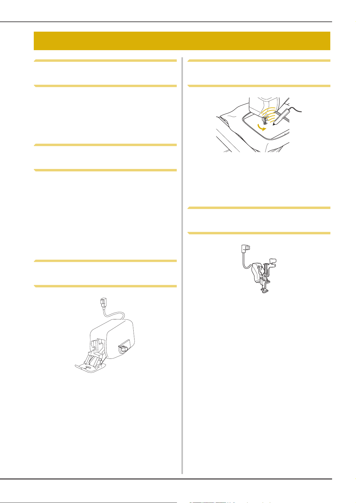
LED Pointer Shows You the
Needle Drop Position
Expanding Your Creativity with
Dual Feed Foot
Do you feel like trying a new material, like thin
fabric or nylon fabric?
Included dual feed foot works very effectively
when sewing those difficult materials. This foot
also works effectively when you sew different
types of materials together, like thin fabric with
thick fabric. You can adjust the feed length for the
various fabric types.
See “Using the Dual Feed Foot” on page B-68.
Included Embroidery foot with LED pointer
indicates the needle position with a red LED point.
The LED pointer shows you the location of the
needle penetration so that it is easier to adjust the
embroidery position.
See “Using the Embroidery Foot “W+” with LED
Pointer” on page B-62.
B-7
Page 10

WHAT YOU CAN DO WITH THIS MACHINE
WHAT YOU CAN DO WITH THIS MACHINE
B Basic operations
After purchasing your machine, be sure to read this section first. This section provides details on the
initial setup procedures as well as descriptions of this machine’s more useful functions.
Chapter 1 Getting Ready
To learn the operation of the principal parts and the
screens
Page B-20
Chapter 2 Sensor Functions
Try the new function using the supplied sensor pen
Page B-72
S Sewing
This section describes procedures for using the various utility stitches as well as other functions. It
provides details on basic machine sewing in addition to the more expressive features of the machine,
from sewing tubular pieces and buttonholes to sewing the character and decorative stitch patterns and
decorative bobbin work.
Chapter 1 Sewing Basics
To learn how to prepare for sewing and basic sewing
operations
Page S-2
Chapter 3 Character/Decorative
Stitches
The variety of stitches widen your creativity
Page S-76
Chapter 2 Utility Stitches
Pre-programmed with more than 100 frequently used
stitches
Page S-20
Chapter 4 How to Create Bobbin
Work (Sewing)
Wind medium to heavy weight thread on a bobbin for
three-dimensional appearance.
Page S-104
E Embroidering
This section gives instruction to embroider designs with this machine.
Chapter 1, “Embroidery”, provides details on sewing embroidery patterns stored on the machine as well
as patterns that have been imported. Chapter 2, “Embroidery Edit”, provides details on editing
embroidery patterns to create custom embroidery. Chapter 3, “How to Create Bobbin Work
(Embroidery)” gives instruction on creating dimensional embroidery.
Chapter 1 Embroidery
Maximum 30 cm × 18 cm (approx. 12 inches × 7 inches)
for large embroidery designs
Page E-2
Chapter 2 Embroidery Edit
Designs can be combined, rotated or enlarged
Page E-56
Chapter 3 How to Create Bobbin
Work (Embroidery)
Medium to heavy weight thread wound on a bobbin can
be embroidered into a three-dimensional design.
Page E-86
A Appendix
This section provides important information for operating this machine.
Chapter 1 Maintenance and Troubleshooting
Find troubleshooting tips and pointers as well as how to keep your machine in the best working condition.
Page A-2
B-8
Page 11

CONTENTS
CONTENTS
TRADEMARKS
INTRODUCTION................................................. 1
IMPORTANT SAFETY INSTRUCTIONS ................ 1
OUTSTANDING FEATURES ................................. 7
WHAT YOU CAN DO WITH THIS MACHINE..... 8
NAMES OF MACHINE PARTS AND THEIR
FUNCTIONS........................................................ 12
Machine .............................................................................. 12
Needle and Presser Foot Section .......................................... 13
Embroidery Unit .................................................................. 14
Operation Buttons................................................................ 14
Using the Flat Bed Attachment............................................. 15
Included Accessories ........................................................... 16
Options................................................................................ 18
B Basic operations
Chapter1 Getting Ready 20
TURNING THE MACHINE ON/OFF .................. 21
Setting Your Machine for the First Time ............................... 22
LCD SCREEN ...................................................... 24
Using the Machine Setting Mode Key ................................. 28
Using the Sewing Machine Help Key .................................. 36
Using the Operation Guide Function ................................... 37
Using the Sewing Guide Function........................................ 38
Using the Pattern Explanation Function ................................ 39
LOWER THREADING ......................................... 40
Winding the Bobbin............................................................. 40
Setting the Bobbin................................................................ 45
Pulling Up the Bobbin Thread.............................................. 47
UPPER THREADING .......................................... 48
Upper Threading.................................................................. 48
Using the Twin Needle Mode .............................................. 52
Using Threads that Unwind Quickly .................................... 54
CHANGING THE PRESSER FOOT ...................... 55
Removing the Presser Foot ................................................... 55
Attaching the Presser Foot.................................................... 55
Attaching the Presser Foot with the Included Adapter .......... 55
CHANGING THE NEEDLE.................................. 57
ABOUT THE NEEDLE AND FABRIC ................... 59
About the Needle................................................................. 59
Fabric/Thread/Needle Combinations.................................... 60
BEFORE EMBROIDERING .................................. 61
Embroidery Step by Step ...................................................... 61
Using the Embroidery Foot “W+” with LED Pointer.............. 62
Attaching the Embroidery Unit............................................. 65
USING FUNCTIONS BY CONNECTING THE
ACCESSORY TO THE MACHINE ........................ 67
Using USB Media or Embroidery Card Reader/USB Card Writer
Module* .............................................................................. 67
Connecting the Machine to the Computer............................ 67
Using a USB Mouse ............................................................. 68
Using the Dual Feed Foot .................................................... 68
Chapter2 Sensor Functions 72
CONVENIENT SEWING FEATURES BY USING THE
SENSOR PEN ...................................................... 73
CONNECTING THE SENSOR PEN ..................... 73
Using the Sensor Pen Holder ............................................... 74
USING THE SENSOR PEN .................................. 75
Using the Sensor Pen ........................................................... 75
Important Information about Sensor Pen .............................. 75
Calibrating the Sensor Pen.................................................... 76
USING SENSOR FUNCTIONS WITH SEWING
STITCH .............................................................. 78
Sensor Function Area ........................................................... 78
Specifying the Guideline Marker Position
With the Sensor Pen ............................................................. 78
Specifying the Needle Drop Position With the Sensor Pen.... 80
Using the Sensor Pen to Specify the Stitching Width and Stitch
Position................................................................................ 81
Using the Sensor Pen to Specify the Sewing End Point.......... 83
USING SENSOR FUNCTIONS IN
“EMBROIDERY”/“EMBROIDERY EDIT” MODE
Specifying the Embroidering Position With the Sensor Pen ... 85
...... 85
S Sewing
Chapter1 Sewing Basics 2
SEWING .............................................................. 3
Sewing a Stitch....................................................................... 3
Sewing Reinforcement Stitches............................................... 5
Automatic Reinforcement Stitching ........................................ 5
Sewing Curves........................................................................ 7
Changing Sewing Direction.................................................... 7
Sewing Heavyweight Fabrics.................................................. 7
Sewing Hook-and-Loop Fastener ............................................ 8
Sewing Lightweight Fabrics .................................................... 9
Sewing Stretch Fabrics............................................................ 9
STITCH SETTINGS ............................................. 10
Setting the Stitch Width........................................................ 10
Setting the Stitch Length ....................................................... 10
Setting the “L/R SHIFT”......................................................... 11
Setting the Thread Tension ................................................... 12
USEFUL FUNCTIONS ........................................ 13
Automatic Thread Cutting .................................................... 13
Adjusting the Needle Drop Position with the Guideline Marker
(For models equipped with the guideline marker)................. 14
Using the Knee Lifter............................................................ 15
Pivoting................................................................................ 15
Automatic Fabric Sensor System (Automatic Presser Foot
Pressure)............................................................................... 17
Needle Position – Stitch Placement ...................................... 18
Locking the Screen............................................................... 18
Chapter2 Utility Stitches 20
SELECTING UTILITY STITCHES ......................... 21
Selecting a Stitch .................................................................. 21
Saving Your Stitch Settings ................................................... 22
SEWING THE STITCHES .................................... 24
Straight Stitches .................................................................... 24
Dart Seam ............................................................................ 28
Gathering............................................................................. 29
Flat Fell Seam....................................................................... 29
Pintuck................................................................................. 30
Zigzag Stitches ..................................................................... 31
Elastic Zigzag Stitches .......................................................... 33
Overcasting.......................................................................... 33
Quilting................................................................................ 35
Blind Hem Stitches............................................................... 45
Appliqué .............................................................................. 48
Shelltuck Stitches ................................................................. 49
Scallop Stitches .................................................................... 50
Crazy Quilting...................................................................... 50
Smocking Stitches ................................................................ 51
Fagoting ............................................................................... 52
Tape or Elastic Attaching...................................................... 52
B-9
Page 12

CONTENTS
Heirloom.............................................................................. 53
One-step Buttonholes........................................................... 55
Darning................................................................................ 58
Bar Tacks ............................................................................. 59
Button Sewing...................................................................... 61
Eyelet ................................................................................... 62
Multi-directional Sewing (Straight Stitch and Zigzag Stitch)
Zipper Insertion.................................................................... 64
..... 63
STITCH SETTING CHART................................... 68
Chapter3 Character/Decorative Stitches 76
SELECTING STITCH PATTERNS.......................... 77
Selecting Decorative Stitch Patterns/7mm Decorative Stitch
Patterns/Satin Stitch Patterns/7mm Satin Stitch
Patterns/Cross Stitch/Utility Decorative Stitch Patterns.......... 78
Characters............................................................................ 78
SEWING STITCH PATTERNS .............................. 81
Sewing Attractive Finishes .................................................... 81
Basic Sewing........................................................................ 81
Making Adjustments............................................................. 82
EDITING STITCH PATTERNS ............................. 84
Changing the Size ................................................................ 86
Changing the Length (for 7mm Satin Stitch Patterns Only) .... 87
Creating a Vertical Mirror Image .......................................... 87
Creating a Horizontal Mirror Image...................................... 87
Sewing a Pattern Continuously ............................................. 87
Changing Thread Density (for Satin Stitch Patterns Only)...... 88
Returning to the Beginning of the Pattern ............................. 88
Checking the Image.............................................................. 89
COMBINING STITCH PATTERNS ...................... 90
Before Combining ................................................................ 90
Combining Various Stitch Patterns........................................ 90
Combining Large and Small Stitch Patterns........................... 91
Combining Horizontal Mirror Image Stitch Patterns.............. 92
Combining Stitch Patterns of Different Length ...................... 92
Making Step Stitch Patterns
(for 7mm Satin Stitch Patterns Only) ..................................... 93
USING THE MEMORY FUNCTION.................... 95
Stitch Data Precautions ........................................................ 95
Saving Stitch Patterns in the Machine’s Memory................... 96
Saving Stitch Patterns to USB Media..................................... 97
Saving Stitch Patterns in the Computer ................................. 98
Retrieving Stitch Patterns from the Machine’s Memory......... 99
Recalling from USB Media ................................................. 100
Recalling from the Computer.............................................. 101
Chapter4 How to Create Bobbin Work
(Sewing) 104
ABOUT BOBBIN WORK .................................. 105
PREPARING FOR BOBBIN WORK ................... 105
Required Materials ............................................................. 105
Upper Threading................................................................ 106
Preparing the Bobbin Thread .............................................. 107
CREATING BOBBIN WORK ............................. 111
Positioning the Fabric and Sewing...................................... 111
Bobbin Work Free Motion Sewing...................................... 113
ADJUSTING THE THREAD TENSION .............. 114
TROUBLESHOOTING ...................................... 115
E Embroidering
Chapter1 Embroidery 2
SELECTING PATTERNS......................................... 3
Selecting Embroidery Patterns/Baby Lock “Exclusives”/Floral
Alphabet/Bobbin Work Patterns ............................................. 4
Selecting Character Patterns ................................................... 5
Selecting Frame Patterns......................................................... 7
Selecting Patterns from Embroidery Cards .............................. 7
Selecting Patterns from USB Media/Computer ....................... 8
VIEWING THE EMBROIDERING SCREEN ........... 9
PREPARING THE FABRIC .................................. 11
Attaching Iron-on Stabilizers (Backing) to the Fabric............ 11
Hooping the Fabric in the Embroidery Frame....................... 13
Embroidering Small Fabrics or Fabric Edges......................... 16
ATTACHING THE EMBROIDERY FRAME .......... 17
CONFIRMING THE PATTERN POSITION ......... 19
Checking the Pattern Position .............................................. 19
Previewing the Completed Pattern....................................... 20
SEWING AN EMBROIDERY PATTERN............... 21
Embroidering Attractive Finishes.......................................... 21
Sewing Embroidery Patterns................................................. 22
Sewing Embroidery Patterns Which Use Appliqué ............... 23
ADJUSTMENTS DURING THE EMBROIDERY
PROCESS............................................................. 26
If the Bobbin Runs Out of Thread ........................................ 26
If the Thread Breaks During Sewing ..................................... 27
Restarting from the Beginning .............................................. 28
Resuming Embroidery After Turning Off the Power .............. 28
MAKING EMBROIDERY ADJUSTMENTS........... 30
Adjusting Thread Tension .................................................... 30
Adjusting the Bobbin Case (with No Color on the Screw) .... 31
Using the Automatic Thread Cutting Function
(END COLOR TRIM)............................................................ 32
Using the Thread Trimming Function (JUMP STITCH TRIM)
Adjusting the Embroidery Speed.......................................... 33
Changing the Thread Color Display ..................................... 34
Changing the “Embroidery Frame Display”.......................... 35
....... 32
REVISING THE PATTERN................................... 36
Moving the Pattern .............................................................. 36
Aligning the Pattern and the Needle .................................... 36
Changing the Size of the Pattern .......................................... 37
Rotating the Pattern ............................................................. 38
Creating a Horizontal Mirror Image ..................................... 39
Enlarging the Editing Screen................................................. 39
Changing the Density (Alphabet Character and Frame
Patterns Only)...................................................................... 40
Changing the Colors of Alphabet Character Patterns............ 40
Embroidering Linked Characters .......................................... 41
Uninterrupted Embroidering (Monochrome - Using a Single
Color) .................................................................................. 43
USING THE MEMORY FUNCTION ................... 44
Embroidery Data Precautions............................................... 44
Saving Embroidery Patterns in the Machine’s Memory ......... 46
Saving Embroidery Patterns to USB Media ........................... 47
Saving Embroidery Patterns in the Computer ....................... 48
Retrieving Patterns from the Machine’s Memory.................. 49
Recalling from USB Media................................................... 50
Recalling from the Computer............................................... 51
EMBROIDERY APPLICATIONS .......................... 52
Using a Frame Pattern to Make an Appliqué (1) ................... 52
Using a Frame Pattern to Make an Appliqué (2) ................... 53
Sewing Split Embroidery Patterns......................................... 54
Chapter2 Embroidery Edit 56
EXPLANATION OF FUNCTIONS....................... 57
SELECTING PATTERNS TO EDIT ....................... 58
Selecting Embroidery Patterns/Baby Lock “Exclusives”/Floral
Alphabet Patterns/Frame/Bobbin Work Patterns ................... 59
Selecting Alphabet Character Patterns.................................. 59
EDITING PATTERNS .......................................... 61
Moving the Pattern .............................................................. 63
Rotating the Pattern ............................................................. 63
Changing the Size of the Pattern .......................................... 63
Deleting the Pattern............................................................. 63
Displaying Patterns in the Screen Magnified by 200% ......... 63
Changing the Configuration of Character Patterns................ 64
Changing Character Spacing................................................ 64
Reducing Character Spacing................................................ 65
Separating Combined Character Patterns ............................. 65
B-10
Page 13

CONTENTS
Changing the Color of Each Alphabet Character in a Pattern
Embroidering Linked Characters .......................................... 67
Changing the Thread Color .................................................. 67
Creating a Custom Thread Table.......................................... 68
Choosing a Color from the Custom Thread Table ................. 72
Designing Repeated Patterns................................................ 73
Embroidering the Pattern Repeatedly ................................... 77
Duplicating a Pattern ........................................................... 79
After Editing......................................................................... 79
COMBINING PATTERNS ................................... 80
Editing Combined Patterns ................................................... 80
Sewing Combined Patterns .................................................. 83
VARIOUS EMBROIDERING FUNCTIONS ......... 84
Uninterrupted Embroidering (Monochrome - Using a Single
Color) .................................................................................. 84
Basting Embroidery.............................................................. 84
USING THE MEMORY FUNCTION.................... 85
Chapter3 How to Create Bobbin Work
(Embroidery) 86
ABOUT BOBBIN WORK .................................... 87
PREPARING FOR BOBBIN WORK ..................... 87
Required Materials............................................................... 87
Upper Threading.................................................................. 88
Preparing the Bobbin Thread ............................................... 88
CREATING BOBBIN WORK............................... 92
Selecting the Pattern ............................................................ 92
Start Embroidering ............................................................... 93
ADJUSTING THE THREAD TENSION ................ 96
TROUBLESHOOTING ........................................ 97
....... 66
A Appendix
Chapter1
CARE AND MAINTENANCE................................. 3
Restrictions on oiling ............................................................. 3
Precautions on storing the machine ....................................... 3
Cleaning the LCD Screen....................................................... 3
Cleaning the Machine Casing ................................................ 3
Cleaning the Race.................................................................. 3
Cleaning the Cutter in the Bobbin Case Area ......................... 5
About the Maintenance Message ........................................... 5
ADJUSTING THE SCREEN .................................... 6
Adjusting the Brightness of the Screen Display....................... 6
Touch Panel is Malfunctioning............................................... 6
TROUBLESHOOTING .......................................... 7
Frequent troubleshooting topics ............................................. 7
Upper thread is too tight ........................................................ 7
Tangled thread on wrong side of fabric .................................. 8
Incorrect thread tension ....................................................... 10
Fabric is caught in the machine and cannot be removed ...... 11
List of Symptoms.................................................................. 14
ERROR MESSAGES ............................................. 18
SPECIFICATIONS ............................................... 21
UPGRADING YOUR MACHINE’S SOFTWARE
Upgrade Procedure Using USB Media ................................. 22
Upgrade Procedure Using Computer ................................... 23
INDEX ................................................................ 24
Maintenance and Troubleshooting
2
..... 22
B-11
Page 14
NAMES OF MACHINE PARTS AND THEIR FUNCTIONS
NAMES OF MACHINE PARTS AND THEIR FUNCTIONS
The names of the various parts of the sewing machine and their functions are described below. Before
using the sewing machine, carefully read these descriptions to learn the names of the machine parts.
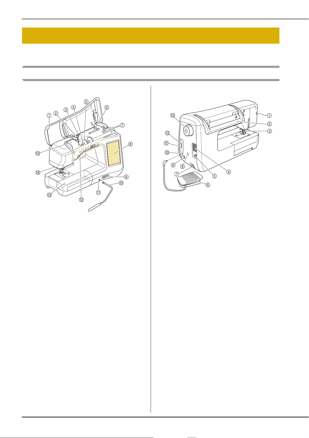
Machine
■ Front View
a Top cover
Open the top cover to thread the machine and wind the
bobbin.
b Pre-tension disk
Pass the thread around the pre-tension disk when winding the
bobbin thread. (page B-40)
c Thread guide for bobbin winding
Pass the thread through this thread guide when winding the
bobbin thread. (page B-40)
d Spool pin
Place a spool of thread on the spool pin. (page B-48)
e Spool cap
Use the spool cap to hold the spool of thread in place.
(page B-48)
f Supplemental spool pin
Use this spool pin to wind the bobbin thread, or to sew with the
twin needle. (page B-40, B-52)
g Bobbin winder
Use the bobbin winder when winding the bobbin. (page B-40)
h LCD (liquid crystal display)
Settings for the selected stitch and error messages appear in
the LCD. (page B-24)
i Speaker
j Knee lifter
Use the knee lifter to raise and lower the presser foot.
(page S-15)
k Knee lifter slot
Insert the knee lifter into the slot. (page S-15)
l Operation buttons (7 buttons) and sewing speed
controller
Use these buttons and the slide to operate the sewing
machine. (page B-14)
m Flat bed attachment with accessory compartment
Store presser feet and bobbins in the accessory compartment
of the flat bed attachment. When sewing cylindrical pieces,
remove the flat bed attachment. (page B-15)
n Thread cutter
Pass the threads through the thread cutter to cut them.
(page B-50)
o Thread guide plate
Pass the thread around the thread guide plate when threading
upper thread. (page B-48)
■ Right-side/Rear View
a Connector for the presser foot
Connect the dual feed foot or embroidery foot with LED
pointer. (page B-62, B-68)
b Handle
Carry the sewing machine by its handle when transporting the
machine.
c Presser foot lever
Raise and lower the presser foot lever to raise and lower the
presser foot. (page B-55)
d Air vent
The air vent allows the air surrounding the motor to circulate.
Do not cover the air vent while the sewing machine is being
used.
e Main power switch
Use the main power switch to turn the sewing machine ON and
OFF. (page B-21)
f Foot controller
Depress the foot controller to control the speed of the machine.
(page S-4)
g Power cord receptacle
Insert the power cord into the machine receptacle. (page B-21)
h Sensor pen holder connector
Connect the included sensor pen holder. (page B-74)
i Sensor pen jack
Connect the sensor pen. (page B-73)
j Foot controller jack
Insert the foot controller plug into its jack on the machine.
(page S-4)
k USB port for computer
In order to import/export patterns between a computer and the
machine, plug the USB cable into the USB port. (page B-67,
S-98, E-48)
l USB port for mouse / media
In order to send patterns from/to USB media, plug the USB
media directly into the USB port. (page B-67, S-97, E-47)
Connect the USB mouse to operate with mouse. (page B-68)
m Handwheel
Rotate the handwheel toward you (counterclockwise) to raise
and lower the needle. The wheel should be turned toward the
front of the machine.
B-12
Page 15
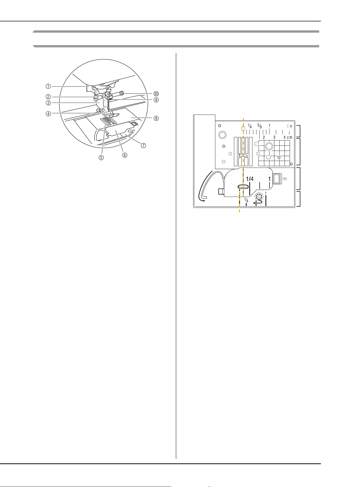
Needle and Presser Foot Section
a
b
c
d
e
f
a Buttonhole lever
The buttonhole lever is used with the one-step buttonhole foot
to create buttonholes. (page S-55)
b Presser foot holder screw
Use the presser foot holder screw to hold the presser foot in
place. (page B-55, B-62)
c Presser foot holder
The presser foot is attached to the presser foot holder.
(page B-55)
d Presser foot
The presser foot consistently applies pressure to the fabric as
sewing takes place. Attach the appropriate presser foot for the
selected stitch. (page B-55)
e Feed dogs
The feed dogs feed the fabric in the sewing direction.
f Bobbin cover
Open the bobbin cover to set the bobbin. (page B-45, S-32)
g Needle plate cover
Remove the needle plate cover to clean the race. (page S-26,
E-22)
h Needle plate
The needle plate is marked with guides to help sew straight
seams. (page S-26)
i Needle bar thread guide
Pass the upper thread through the needle bar thread guide.
(page B-48)
j Needle clamp screw
Use the needle clamp screw to hold the needle in place.
(page B-57)
NAMES OF MACHINE PARTS AND THEIR FUNCTIONS
Measurements on the needle plate, bobbin cover
(with mark) and needle plate cover
The measurements on the needle plate and bobbin
cover are references for patterns with a middle
(center) needle position. The measurements on the
needle plate cover are references for stitches with
a left needle position.
a For stitches with a middle (center) needle position
b For stitches with a left needle position
c Middle (center) needle position <inch>
d Middle (center) needle position <cm>
e Middle (center) needle position <inch>
f Left needle position <inch>
B-13
Page 16
NAMES OF MACHINE PARTS AND THEIR FUNCTIONS
CAUTION
Embroidery Unit
a Carriage
The carriage moves the embroidery frame automatically when
embroidering. (page B-65)
b Release button (located under the embroidery unit)
Press the release button to remove the embroidery unit.
(page B-65)
c Embroidery frame holder
Insert the embroidery frame into the embroidery frame holder
to hold the frame in place. (page E-17)
d Frame-securing lever
Press the frame-securing lever down to secure the embroidery
frame. (page E-17)
e Embroidery unit connection
Insert the embroidery unit connection into the connection port
when attaching the embroidery unit. (page B-65)
• Before inserting or removing the embroidery
unit, turn the main power to OFF.
• After the embroidery frame is set in the frame
holder, be sure the frame-securing lever is
correctly lowered.
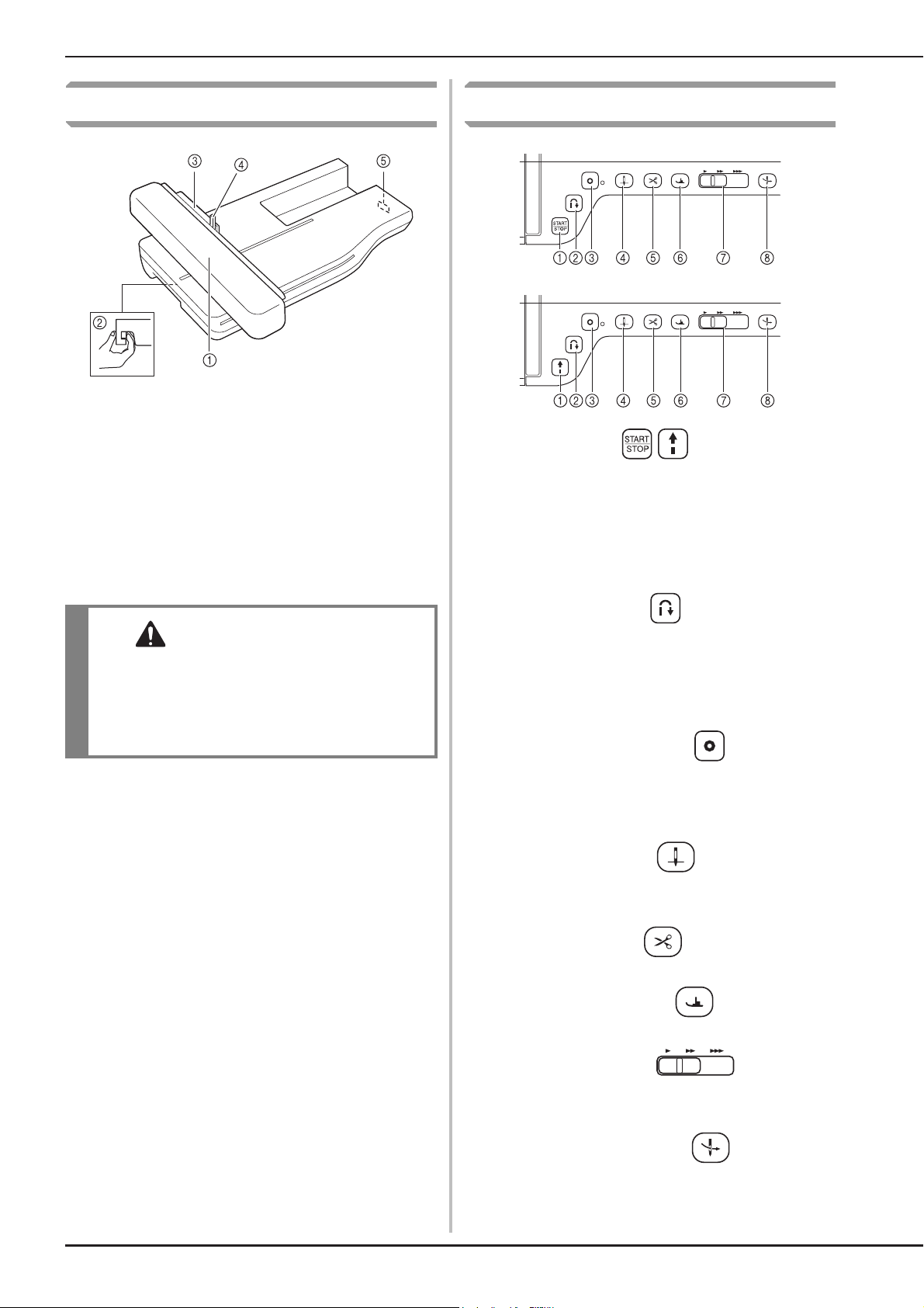
Operation Buttons
a “Start/Stop” button
Press this button and the machine will sew a few stitches at a
slow speed and then begin sewing at the speed set by the
sewing speed controller. Press the button again to stop the
machine. Hold the button in to sew at the machine’s slowest
speed. The button changes color according to the machine’s
operation mode.
Green: The machine is ready to sew or is sewing.
Red: The machine cannot sew.
b “Reverse Stitch” button
For straight, zigzag, and elastic zigzag stitch patterns that take
reverse stitches, the machine will sew reverse stitches at low
speed only while holding down the “Reverse Stitch” button.
The stitches are sewn in the opposite direction. For other
stitches, use this button to sew reinforcement stitches at the
beginning and end of sewing. Press and hold this button, and
the machine sews 3 stitches in the same spot and stops
automatically. (see page S-5)
c “Reinforcement Stitch” button
Use this button to sew a single stitch repeatedly and tie-off. For
character/decorative stitches, press this button to end with a
full pattern instead of mid-point. The LED light beside this
button lights up while the machine is stitching the last full motif,
and automatically turns off when the sewing is stopped. (see
page S-5)
B-14
d “Needle Position” button
Use this button when changing sewing direction or for detailed
sewing in small areas. Press this button to raise or lower the
needle position. With this button, you can lower and raise the
needle to sew a single stitch.
e “Thread Cutter” button
Press this button after sewing to automatically trim the excess
thread.
f “Presser Foot Lifter” button
Press this button to lower the presser foot and apply pressure
to the fabric. Press this button again to raise the presser foot.
g Sewing Speed controller
Use this controller to adjust the sewing speed. Move the slide
to the left to sew at slower speeds. Move the slide to the right
to sew at higher speeds. Beginners should sew at a slow
speed.
h “Automatic Threading” button
Use this button to automatically thread the needle.
Page 17
CAUTION
• Do not press the thread cutter button after the
threads have been cut. The needle may break
and threads may become tangled, or damage
to the machine may occur.
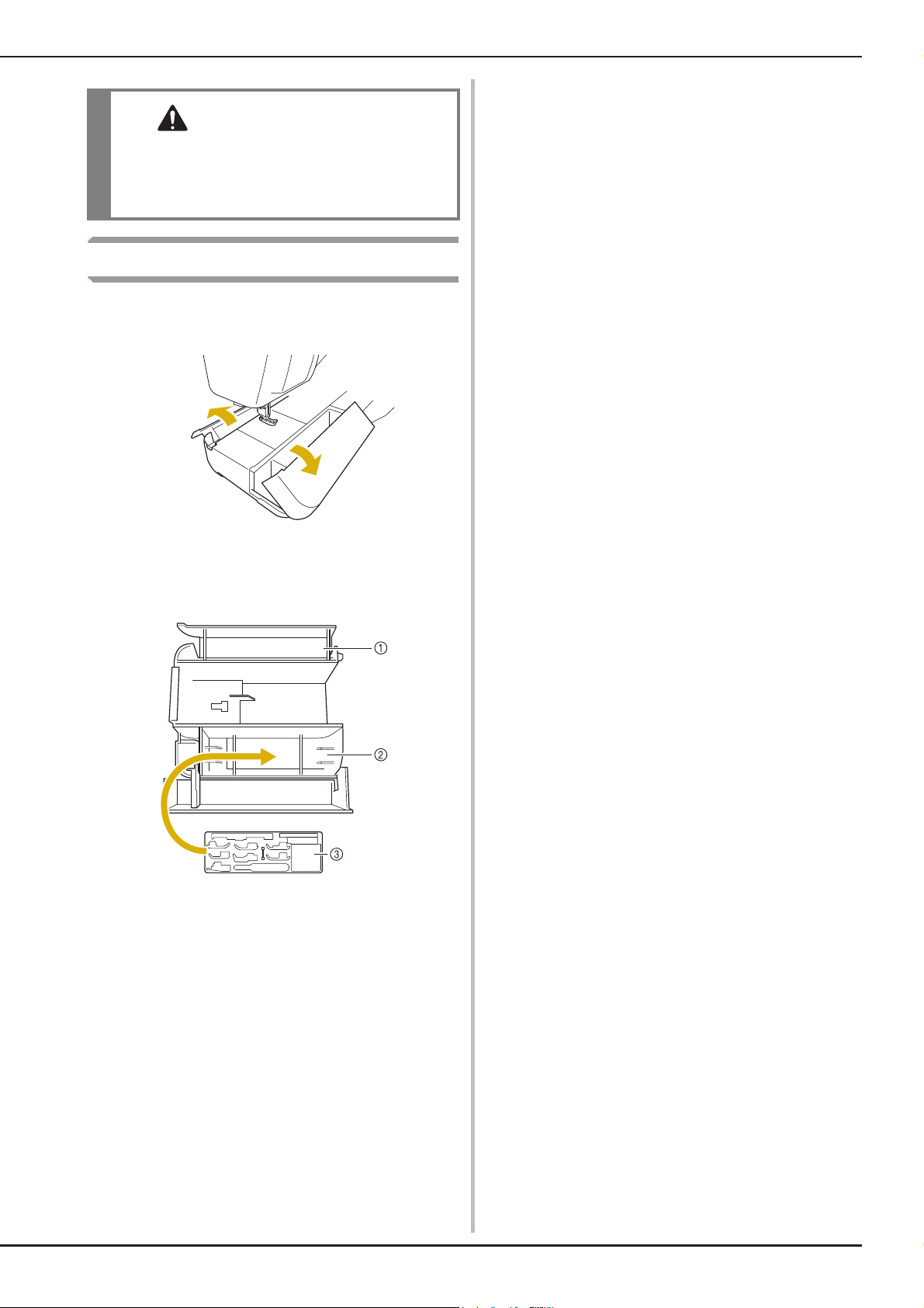
Using the Flat Bed Attachment
Pull the top of the flat bed attachment to open the
accessory compartment.
NAMES OF MACHINE PARTS AND THEIR FUNCTIONS
A presser foot storage tray is stored in the accessory
compartment of the flat bed attachment.
a Storage space of the flat bed attachment
b Presser foot storage space of the flat bed
attachment
c Presser foot storage tray
There are also storage spaces for optional presser
feet.
B-15
Page 18
NAMES OF MACHINE PARTS AND THEIR FUNCTIONS
75/11 2 needles
90/14 2 needles
90/14 2 needles:
Ball point needle (gold colored)
2.0/11 needle
75/11
2 needles
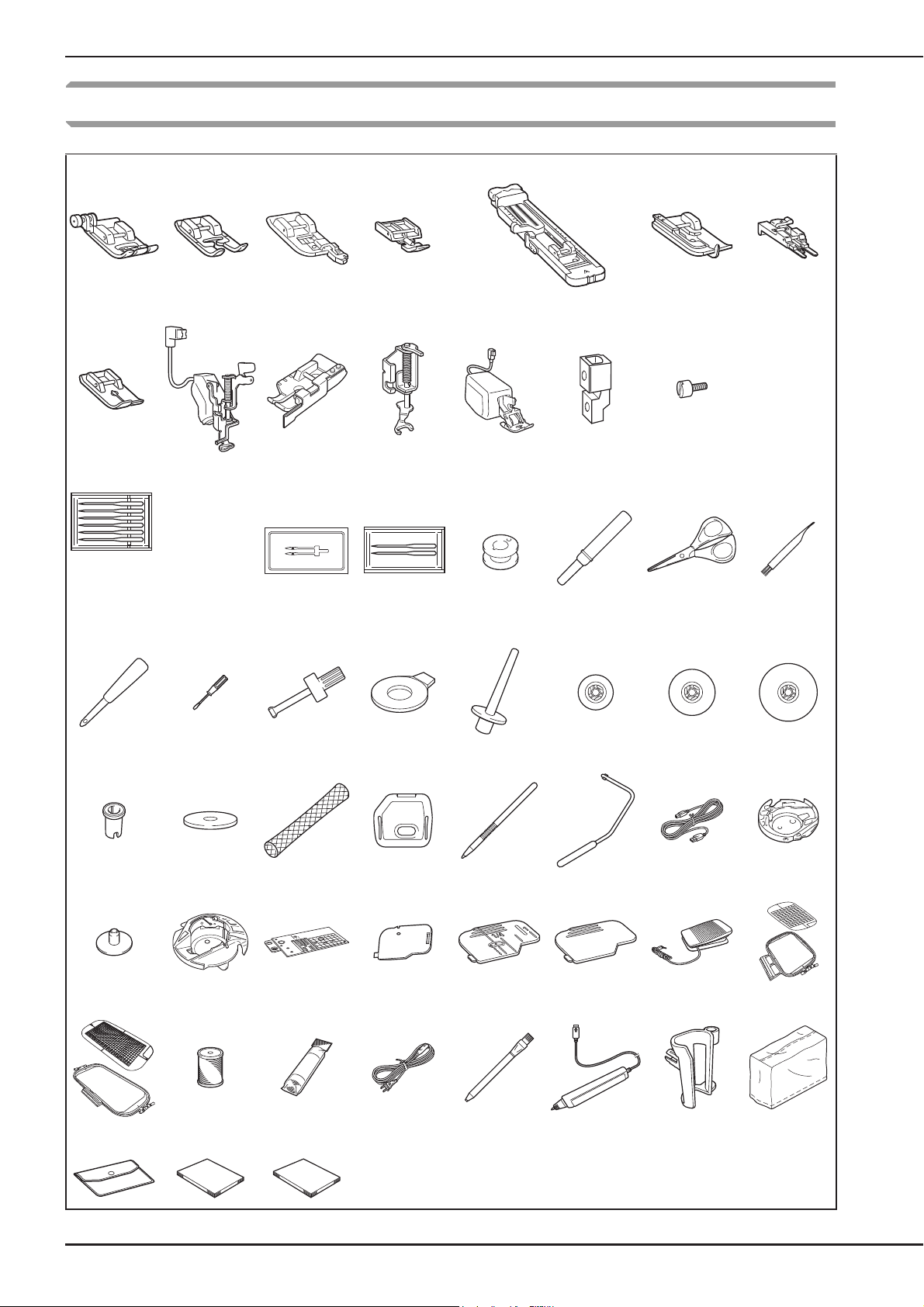
Included Accessories
12345 67
89
15 16 17 18 19 20 21
22 23 24 25 26 27 28 29
30 31 32 33 34 35 36 37
10
11
12
13 14
38 39 40 41 42 43 44 45
46 47 48 49 50 51 52 53
54 55 56
B-16
Page 19
NAMES OF MACHINE PARTS AND THEIR FUNCTIONS
Memo
No. Part Name Part Code
1 Zigzag foot “J” (on machine) XF3022-001
2 Monogramming foot “N” X53840-351
3 Overcasting foot “G” XC3098-051
4 Zipper foot “I” X59370-051
5 Buttonhole foot “A” X57789-251
6 Blind stitch foot “R” X56409-051
7 Button fitting foot “M” 130489-001
8 Straight stitch foot XD0826-051
9 Embroidery foot “W+” with
LED pointer
10 1/4” quilting foot with guide XC6800-251
11 Free motion open toe quilting
foot “O”
12 Dual feed foot XF4068-001
13 Adapter XF3613-001
14 Screw (small) XA4813-051
15 Needle set X58358-051
16 Twin needle X59296-151
17 Ball point needle set XD0705-051
18 Bobbin × 10
(One is on machine.)
19 Seam ripper XF4967-001
20 Scissors XC1807-121
21 Cleaning brush X59476-051
22 Eyelet punch XZ5051-001
23 Screwdriver (small) X55468-051
24 Screwdriver (large) XC4237-021
25 Disc-shaped screwdriver XC1074-051
26 Vertical spool pin XC8619-052
27 Spool cap (small) 130013-154
28 Spool cap (medium) × 2
(One is on machine.)
29 Spool cap (large) 130012-054
30 Spool cap (mini insert) XA5752-121
31 Spool felt (on machine) X57045-051
32 Spool net × 2 XA5523-050
33 Embroidery needle plate
cover
34 Touch pen (stylus) XA9940-051
35 Knee lifter XA6941-052
36 USB cable XD0745-051
37 Alternate bobbin case
(no color on the screw)
38 Bobbin center pin and
instruction sheet
39 Bobbin case (gray, for bobbin
work)
40 Straight stitch needle plate XF3076-001
41 Cord guide bobbin cover
(with single hole)
42 Bobbin cover (with mark) (on
machine)
43 Bobbin cover XE8992-101
44 Foot controller XC8816-051
45 Embroidery frame set (large)
H 180 mm × W 130 mm
(H 7 inches × W 5 inches)
46 Embroidery frame set
(extra large)
H 300 mm × W 180 mm
(H 12 inches × W 7 inches)
47 Embroidery bobbin thread BBT-W
48 Stabilizer material X81176-001
49 Power cord XC6052-051
50 Chalk pencil XE8568-001
XF3124-001
XF4873-001
X52800-150
X55260-153
XE5131-001
XC8167-551
XC8661-251
XE8298-001
XE8991-101
XF0750-101
EF75: Frame
EF79: Embroidery sheet
EF76: Frame
EF80: Embroidery sheet
No. Part Name Part Code
51 Sensor pen holder XF4702-001
52 Pen holder XF2973-001
53 Dust cover XF4694-001
54 Accessory bag XC4487-021
55 Instruction and Reference
Guide
56 Quick Reference Guide XF3649-001
XF3648-001
• Foot controller: Model T
This foot controller can be used on the
machine model: BLTY.
• Always use accessories recommended for
this machine.
B-17
Page 20
NAMES OF MACHINE PARTS AND THEIR FUNCTIONS
Memo
Note
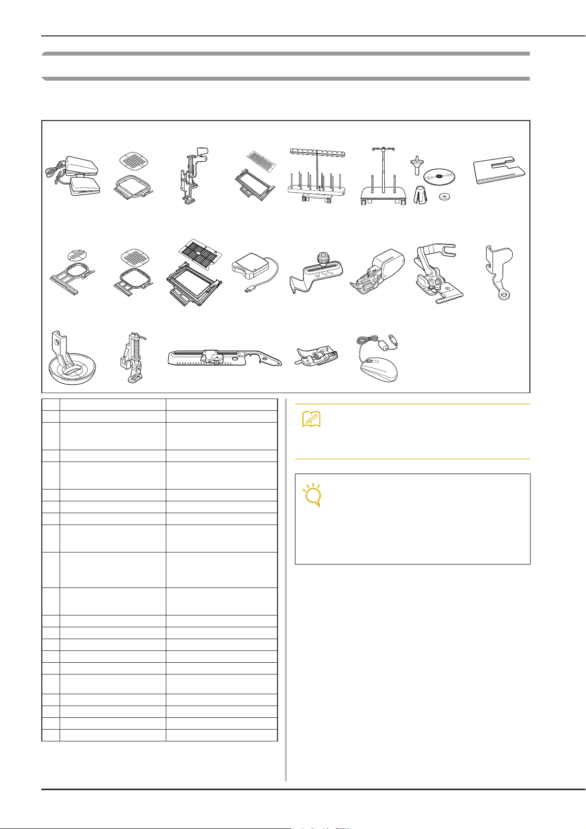
Options
The following are available as optional accessories to be purchased separately from your authorized Baby
Lock retailer.
123456 7
8 9 10 11 12 13 14 15
16 17 18 19 20
No. Part Name Part Code
1 Multi function foot controller BLMA-MFC
2 Square embroidery frame
H 150 mm × W 150 mm (H 6
inches × W 6 inches)
3 Embroidery foot “W” XF4012-001
4 Border embroidery frame
H 300 mm × W 100 mm (H
12 inches × W 4 inches)
5 10 spool stand BLMA-TS
6 2-spool thread stand BLMA-STS
7Extension table BLMA-ET
8 Embroidery frame set (small)
H 20 mm × W 60 mm (H 1
inch × W 2-1/2 inches)
9 Embroidery frame set
(medium)
H 100 mm × W 100 mm (H 4
inches × W 4 inches)
10 Border embroidery frame set
H 180 mm × W 100 mm (H 7
inches × W 4 inches)
11 Embroidery card Reader BLECR
12 Seam guide BLG-SG
13 Walking foot XA8320-103
14 Side cutter foot BLG-SCF
15 Free motion quilting foot “C” XF4737-001
16 Free motion echo quilting
foot “E”
17 Free-motion quilting foot FA2
18 Circular attachment BL-CSA
19 Edge joining foot ESG-EJF
20 USB mouse XE4904-101
BLMA-150
BLMA-CBH
EF73: Frame
EF77: Embroidery sheet
EF74: Frame
EF78: Embroidery sheet
BLSO-BF
XE0766-001
• All specifications are correct at the time of
printing. Please be aware that some
specifications may change without notice.
• Embroidery cards purchased in foreign
countries may not work with your machine.
• Visit your nearest authorized Baby Lock
retailer for a complete listing of optional
accessories and embroidery cards available
for your machine.
B-18
Page 21

Basic
operations
This section provides details on the initial setup procedures as well as descriptions of this machine’s more
useful functions.
Page number starts with “B” in this section.
Chapter1 Getting Ready .......................................................B-20
Chapter2 Sensor Functions ...................................................B-72
Page 22

B Basic operations
Chapter 1
Getting Ready
TURNING THE MACHINE ON/OFF ........................21
Setting Your Machine for the First Time ...................................22
LCD SCREEN............................................................24
■ Home Page Screen ................................................................... 24
■ Utility Stitch Screen .................................................................25
■ Key Functions........................................................................... 26
Using the Machine Setting Mode Key ......................................28
■ Selecting the “Eco Mode” or “Shutoff Support Mode”............. 32
■ Changing the Pointer Shape When a USB Mouse Is Used ........ 32
■ Selecting the Initial Screen Display.......................................... 32
■ Choosing the Display Language................................................ 33
■
Changing the Background Colors of the Embroidery Patterns
■ Specifying the Size of Pattern Thumbnails ............................... 34
■ Saving a Settings Screen Image to USB Media.......................... 35
Using the Sewing Machine Help Key .......................................36
Using the Operation Guide Function ........................................37
Using the Sewing Guide Function .............................................38
Using the Pattern Explanation Function ....................................39
....... 33
LOWER THREADING ..............................................40
Winding the Bobbin..................................................................40
■ Using the Supplemental Spool Pin............................................40
■ Using the Spool Pin.................................................................. 43
■ Untangling Thread from Beneath the Bobbin Winder Seat ...... 44
Setting the Bobbin ....................................................................45
Pulling Up the Bobbin Thread................................................... 47
UPPER THREADING................................................48
Upper Threading....................................................................... 48
Using the Twin Needle Mode ..................................................52
Using Threads that Unwind Quickly .........................................54
■ Using the Spool Net .................................................................54
■ Using the Vertical Spool Pin ....................................................54
CHANGING THE PRESSER FOOT............................55
Removing the Presser Foot........................................................ 55
Attaching the Presser Foot ........................................................ 55
Attaching the Presser Foot with the Included Adapter.............. 55
■ Attaching the Walking foot ...................................................... 56
CHANGING THE NEEDLE.......................................57
Using USB Media or Embroidery Card Reader/USB Card Writer
Module* ................................................................................... 67
Connecting the Machine to the Computer ............................... 67
Using a USB Mouse.................................................................. 68
■ Clicking a Key ...........................................................................68
■ Changing Pages.........................................................................68
Using the Dual Feed Foot......................................................... 68
■ Attaching the Dual Feed Foot ...................................................69
■ Replacing the Sole Part of the Dual Feed Foot..........................69
■ Using the Dual Feed Position Lever ..........................................69
■
Adjusting the Amount of Fabric Feeding of the Dual Feed Foot
.......70
ABOUT THE NEEDLE AND FABRIC......................... 59
About the Needle...................................................................... 59
Fabric/Thread/Needle Combinations ........................................60
BEFORE EMBROIDERING........................................61
Embroidery Step by Step ..........................................................61
Using the Embroidery Foot “W+” with LED Pointer .................62
■ Attaching the Embroidery Foot “W+” with LED Pointer.......... 62
■ Checking the Needle Drop Point With the
Embroidery Foot “W+” with LED Pointer ................................ 63
■ Adjusting the LED Pointer ........................................................ 64
■ Adjusting the Brightness of the LED Pointer............................. 64
Attaching the Embroidery Unit .................................................65
■ About the Embroidery Unit...................................................... 65
■ Removing the Embroidery Unit ............................................... 66
USING FUNCTIONS BY CONNECTING THE
ACCESSORY TO THE MACHINE .............................67
Page 23
TURNING THE MACHINE ON/OFF
WARNING
CAUTION
TURNING THE MACHINE ON/OFF
B
• Use only regular household electricity for the power source. Using other power sources may result in fire,
electric shock, or damage to the machine.
• Make sure that the plugs on the power cord are firmly inserted into the electrical outlet and the power
cord receptacle on the machine.
• Do not insert the plug on the power cord into an electrical outlet that is in poor condition.
• Turn the main power to OFF and remove the plug in the following circumstances:
When you are away from the machine
After using the machine
When the power fails during use
When the machine does not operate correctly due to a bad connection or a disconnection
During electrical storms
• Use only the power cord included with this machine.
• Do not use extension cords or multi-plug adapters with many other appliances plugged in to them. Fire or
electric shock may result.
• Do not touch the plug with wet hands. Electric shock may result.
• When unplugging the machine, always turn the main power to OFF first. Always grasp the plug to remove
it from the outlet. Pulling on the cord may damage the cord, or lead to fire or electric shock.
• Do not allow the power cord to be cut, damaged, modified, forcefully bent, pulled, twisted, or bundled.
Do not place heavy objects on the cord. Do not subject the cord to heat. These things may damage the
cord, or cause fire or electric shock. If the cord or plug is damaged, take the machine to your authorized
retailer for repairs before continuing use.
• Unplug the power cord if the machine is not to be used for a long period of time. Otherwise, a fire may
result.
• When leaving the machine unattended, either the main switch of the machine should be turned to OFF or
the plug must be removed from the socket-outlet.
• When servicing the machine or when removing covers, the machine must be unplugged.
• For U.S.A. only
This appliance has a polarized plug (one blade wider than the other). To reduce the risk of electrical
shock, this plug is intended to fit in a polarized outlet only one way.
If the plug does not fit fully in the outlet, reverse the plug. If it still does not fit, contact a qualified
electrician to install the proper outlet. Do not modify the plug in any way.
1
Getting Ready
Basic operations B-21
Page 24
TURNING THE MACHINE ON/OFF
Note
Memo
CAUTION
Memo
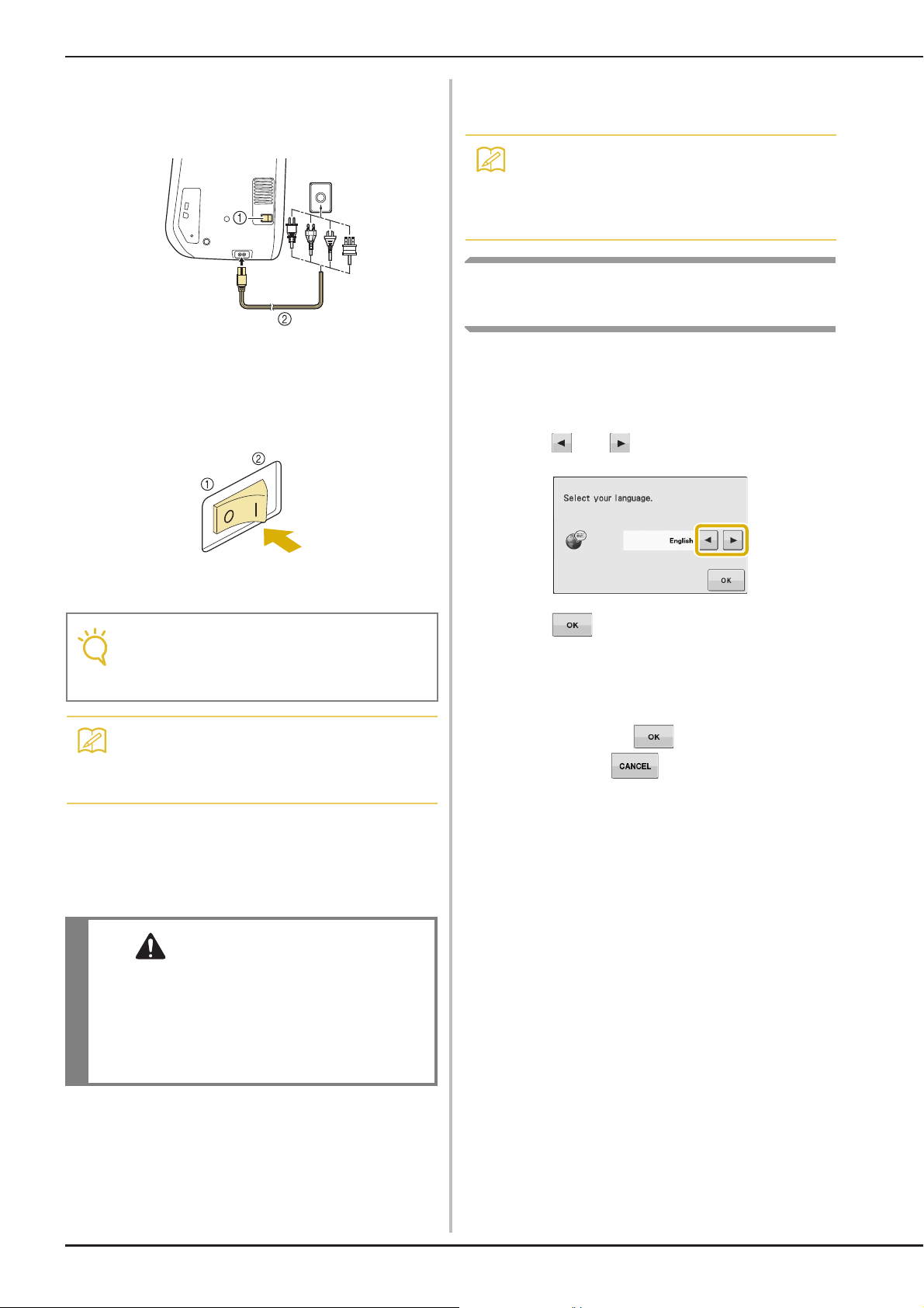
Insert the power supply cord into the power
a
cord receptacle, then insert the plug into a
wall outlet.
a Main power switch
b Power supply cord
Turn the main power switch to “I” to turn
b
on the machine.
Turn the main power switch to “O” to turn
d
off the machine.
• If the machine is turned off in the middle of
sewing in the “Sewing” function, the
operation will not continued after turning the
power on again.
Setting Your Machine for the First
Time
When you first turn on the machine, set the
language and time/date to your language and local
time/date. Follow the procedure below when the
settings screen appears automatically.
Press and to set your local language.
a
a OFF
b ON
• When the straight stitch needle plate is on
the machine, the needle will automatically
move to the middle position.
• When the machine is turned on, the needle
and the feed dogs will make sound when
they move; this is not a malfunction.
When the machine is turned on, the
c
opening movie is played. Touch anywhere
on the screen to display the Home page
screen.
• Only touch the screen with your finger or the
included touch pen. Do not use a sharp pencil,
screwdriver, or other hard or sharp object. It is
not necessary to press hard on the screen.
Pressing too hard or using a sharp object may
damage the screen.
Press .
b
The message screen, confirming if you want
c
to set time/date, appears. To set the
time/date, press ; to cancel the
setting, press .
→ The screen to set time/date appears.
B-22
Page 25
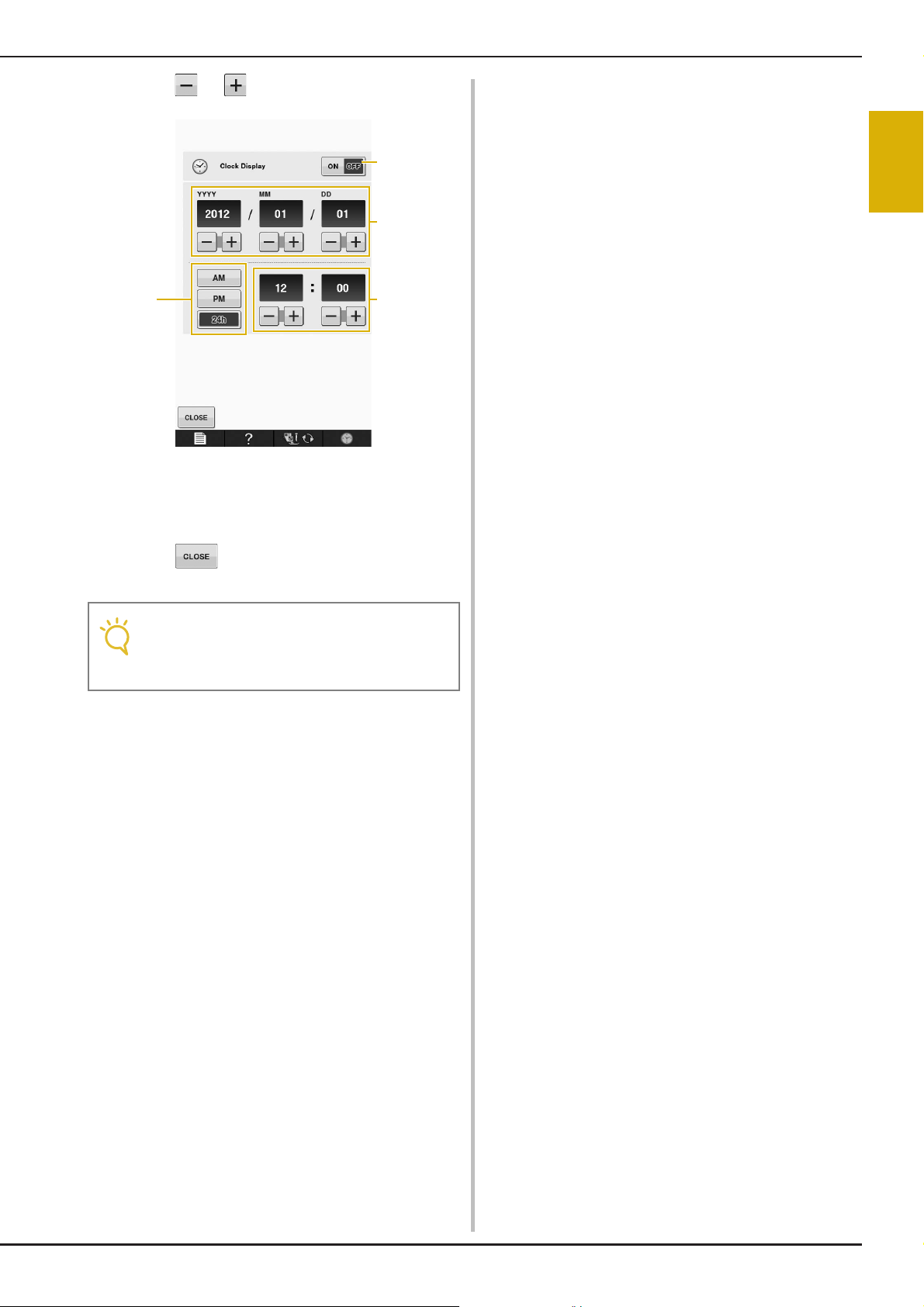
Press or to set time/date.
Note
dc
b
a
d
a Press to display the time on the screen.
b Set the year (YYYY), month (MM) and date (DD).
c Select whether 24h or 12h setting to display.
d Set the current time.
TURNING THE MACHINE ON/OFF
B
1
Getting Ready
Press to start using your machine.
e
→ The clock starts from 0 second of the time you set.
• The time/date you set may be cleared, if
you don’t turn on the machine for a certain
period.
Basic operations B-23
Page 26
LCD SCREEN
CAUTION
b
c
a
LCD SCREEN
• Only touch the screen with your finger or the included touch pen. Do not use a sharp pencil, screwdriver,
or other hard or sharp object. It is not necessary to press hard on the screen. Pressing too hard or using a
sharp object may damage the screen.
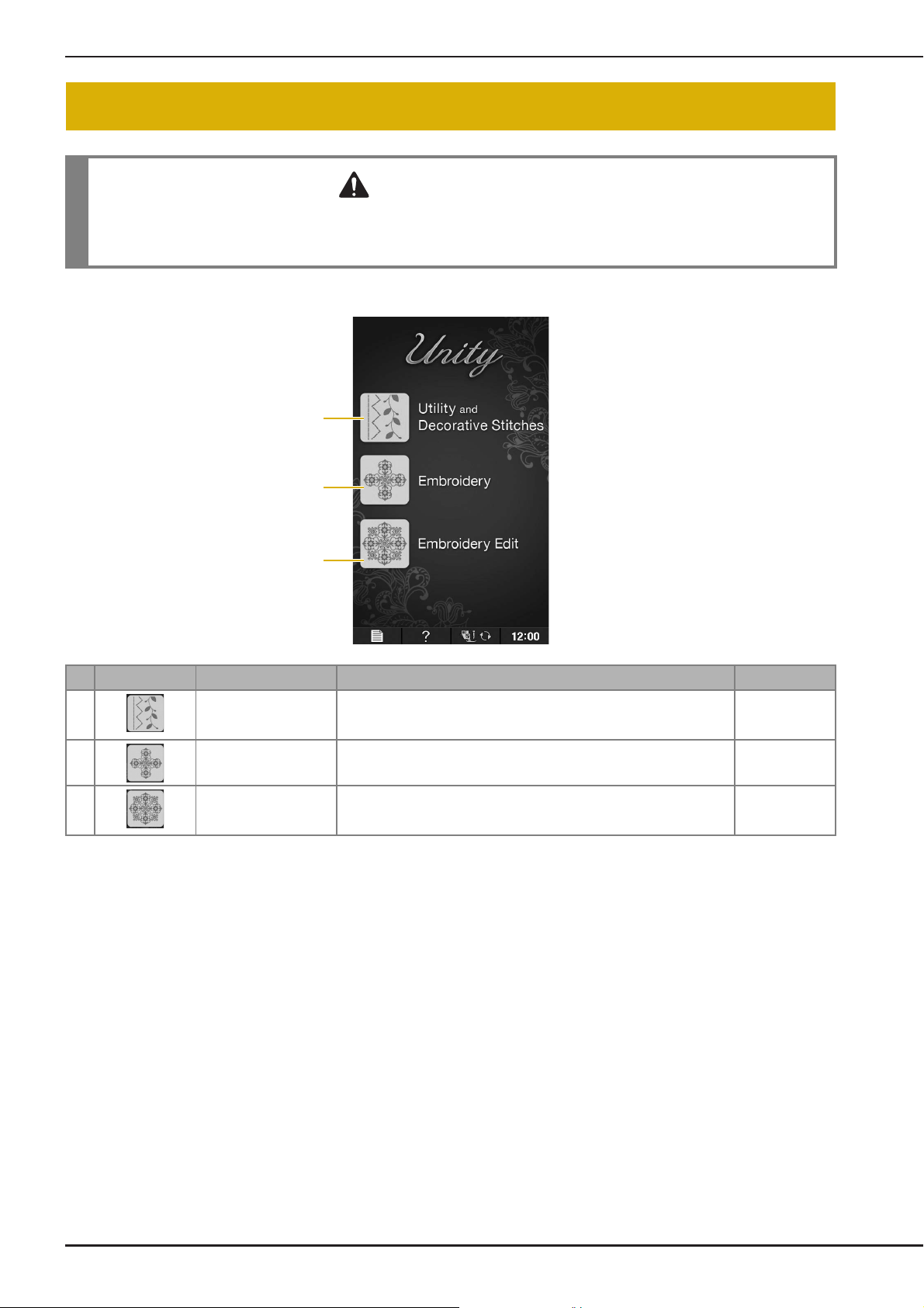
■ Home Page Screen
No. Display Key Name Explanation Page
a “Utility and Decorative
Stitches” key
b “Embroidery” key Attach the embroidery unit and press this key to embroider patterns. E-3
c “Embroidery Edit” key Press this key to combine embroidery patterns. With the “Embroidery
Press this key to sew utility stitches or character or decorative stitch
patterns.
Edit” functions, you can also create original embroidery patterns or
frame patterns.
See the “Key
Functions” table.
B-26
E-58
B-24
Page 27
LCD SCREEN
a
b
d
e
g
c
h
f
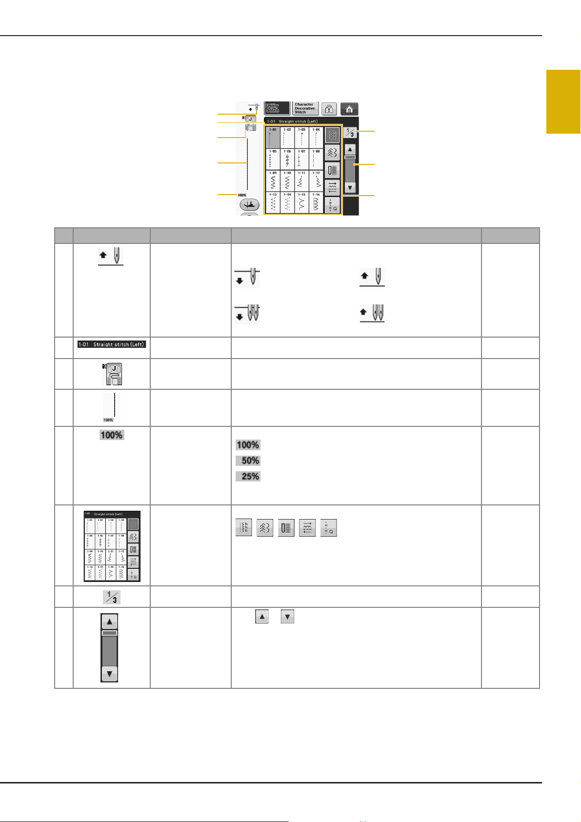
■ Utility Stitch Screen
Press a key with your finger to select the stitch pattern, to select a machine function, or to select an
operation indicated on the key. When the key display is light gray, the function is not currently available.
No. Display Key Name Explanation Page
a Needle position
setting display
Shows single or twin needle mode setting, and the needle stop
position.
–
B
1
Getting Ready
Single needle/down
position
Twin needle/down
position
b Selected stitch
display
c Presser foot display Shows the presser foot code. Attach the presser foot indicated in this
d Stitch preview Shows a preview of the selected stitch. When shown at 100%, the
e Pattern display size Shows the approximate size of the pattern selected.
f Stitch selection
screen
Shows the name and code number of the selected stitch. S-3
display before sewing.
stitch appears in the screen at nearly its actual size.
: Nearly the same size as the sewn pattern
: 1/2 the size of the sewn pattern
: 1/4 the size of the sewn pattern
* The actual size of the sewn pattern may differ depending on the type
of fabric and thread that is used.
Press the key for the pattern you want to sew. Use
Single needle/up position
Twin needle/up position
to change to different stitch groups.
B-55
S-21
S-21
S-21
g Page display Shows additional pages that can be displayed. (Illustration shows page
1 of 3.)
h Scroll key
* All key functions of the LCD are explained in the “Key Functions” table on the following page.
Press or , to move one page at a time, or touch anywhere on
the bar to jump ahead for additional pages of stitches.
Basic operations B-25
–
–
Page 28
LCD SCREEN
a db c
h
j
k
f
lmn
s
p
o
q
r
e
g
i
u
t
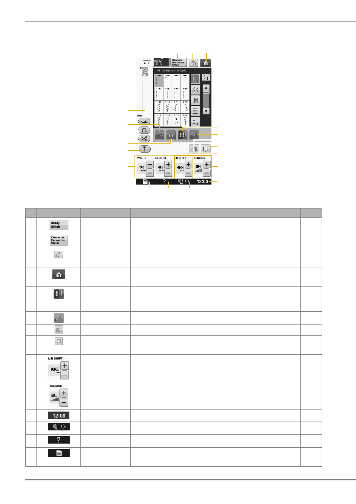
■ Key Functions
No. Display Key Name Explanation Page
a “Utility Stitch” key Press this key to select a straight stitch, zigzag stitch, buttonhole, blind hem
b “Character/
Decorative Stitch” key
c Screen lock key Press this key to lock the screen. When the screen is locked, the various
d Home page screen
key
e Needle mode
selection key
(Single/Double)
f Sensor function key Press this key to use the sensor function. B-78
g Image key Press this key to display an enlarged image of the selected stitch pattern. S-22
h Machine’s memory
key
stitch, or other stitches commonly used in garment construction.
Press this key to select character or decorative stitch patterns. S-77
settings, such as the stitch width and stitch length, are locked and cannot be
changed. Press this key again to unlock the settings.
Press this key anytime it is displayed to return to the home page screen and
select a different category - “Utility and Decorative Stitches”, “Embroidery” or
“Embroidery Edit”.
Press this key to select twin needle sewing mode. The sewing mode changes
between single needle mode and twin needle mode each time you press the
key. If the key display is light gray, the selected stitch pattern cannot be sewn
in the twin needle mode.
Press this key to select from 3 memory functions; retrieving, storing or reset. S-22,
i “L/R SHIFT” key Shows the tendency of Left/Right of the center line of the original zigzag stitch
currently selected stitch pattern.
j Thread tension key Shows the automatic thread tension setting of the currently selected stitch
pattern. You can use the plus and minus keys to change the thread tension
settings.
S-21
S-18
B-24
B-52
S-96,
S-98
S-11
S-12
k Clock key Press this key to set the clock to your local time. B-22
l Presser foot/Needle
m Sewing machine help
n Machine setting
exchange key
key
mode key
B-26
Press this key before changing the needle, the presser foot, etc. This key locks
all key and button functions to prevent operation of the machine.
Press this key to see explanations on how to use the machine. B-36
Press this key to change the needle stop position, change the volume of
operation sound, adjust the pattern or screen, and change other machine
settings.
B-55 to
B-58
B-28
Page 29
LCD SCREEN
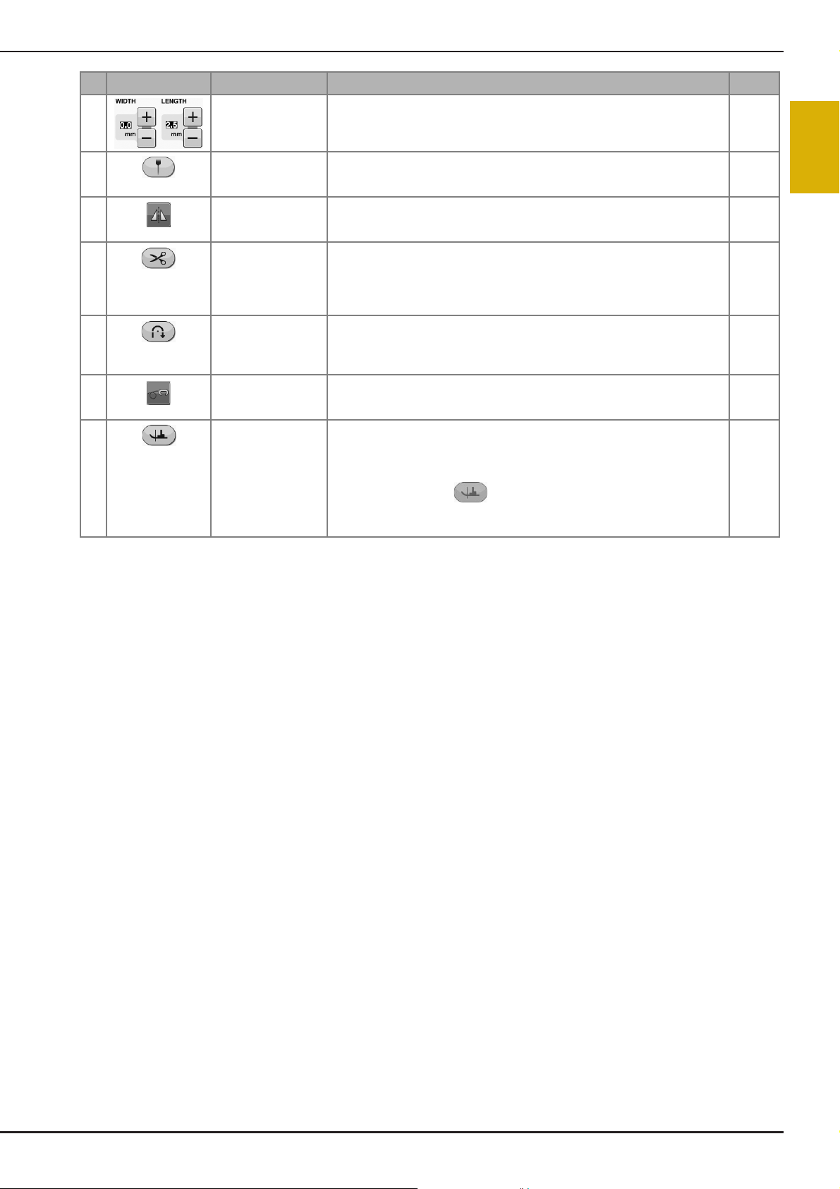
No. Display Key Name Explanation Page
o Stitch width and
stitch length key
Shows the zigzag width and stitch length settings of the currently selected
stitch pattern. You can use the plus and minus keys to adjust the zigzag width
and stitch length settings.
S-10
B
p Guideline marker key Press this key to display the guideline marker along the sewing line. The
q Mirror image key Press this key to create a mirror image of the selected stitch pattern. If the key
r Automatic thread
cutting key
s Automatic
reverse/reinforcement
stitch key
t Free motion mode
key
u Pivot key Press this key to select the pivot setting. When the pivot setting is selected,
guideline marker makes it easier to sew stitches that align with the fabric edge
or other marker on the fabric.
display is light gray, a mirror image of the selected stitch pattern cannot be
sewn.
Press this key to set the automatic thread cutting function. Set the automatic
thread cutting function before sewing to have the machine automatically sew
reinforcement stitches at the beginning and end of sewing (depending on the
pattern, the machine may sew reverse stitches) and trim the threads after
sewing.
Press this key to use the automatic reverse/reinforcement stitching setting.
If you select this setting before sewing, the machine will automatically sew
reverse stitches or reinforcement stitches depending on the pattern, at the
beginning and end of sewing.
Press this key to enter free motion sewing mode.
The presser foot is raised to an appropriate height and the feed dog is lowered
for free motion quilting.
stopping the machine lowers the needle and slightly raises the presser foot
automatically. In addition, when sewing is restarted, the presser foot is
automatically lowered.
• If this key appears as , the pivot function cannot be used.
• Be sure the needle position on page B-29 of Machine Settings is set to the
down position.
For additional operational information, refer to page reference number listed above.
S-14
S-21
S-13
S-5
S-40
S-15
1
Getting Ready
Basic operations B-27
Page 30
LCD SCREEN
Memo
a
b
c
d
e
m
f
h
g
m
i
j
k
l
m
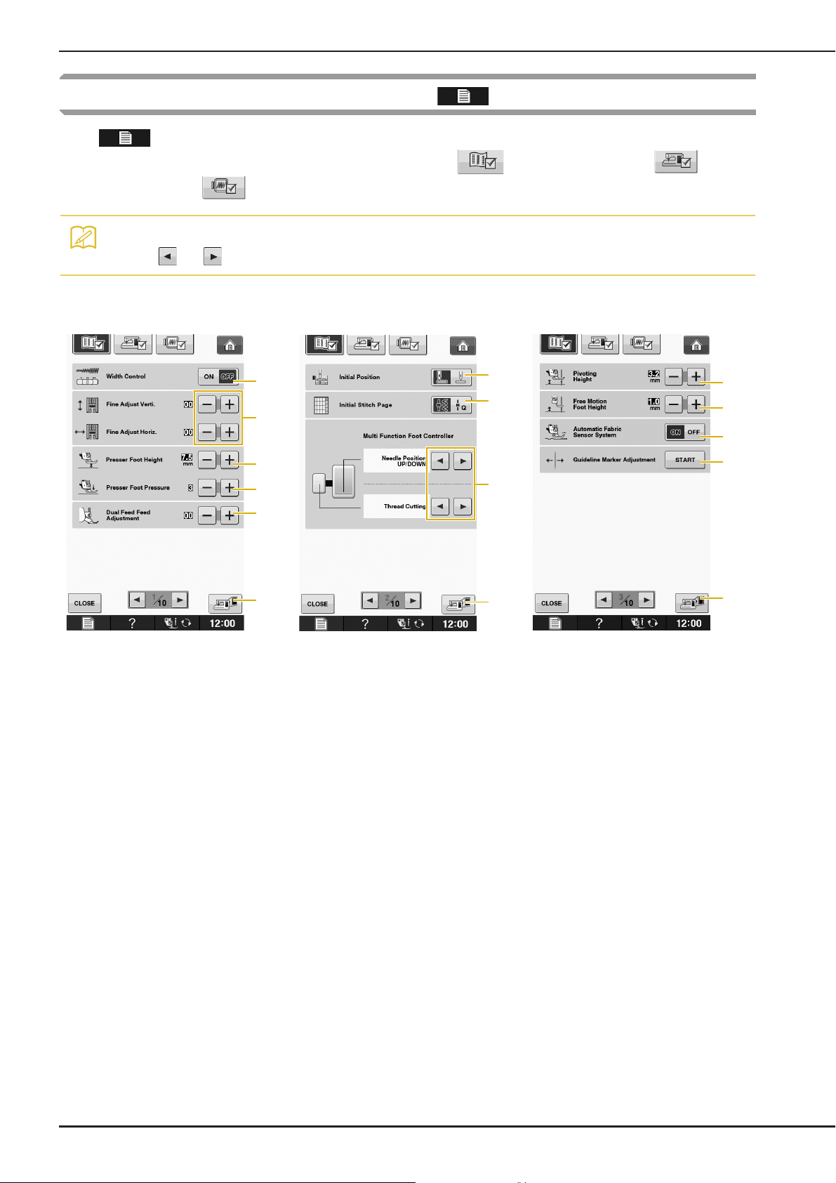
Using the Machine Setting Mode Key
Press to change the default machine settings (needle stop position, embroidery speed, opening
display, etc.). To display the different settings screens, press for “Sewing settings”, for
“General settings” or for “Embroidery settings”.
• Press or next to the page numbers, to display a different settings screen.
Sewing settings
a Select whether to use the sewing speed controller to determine the zigzag width (see page S-39).
b Make adjustments to character or decorative stitch patterns (see page S-82).
c Adjust the presser foot height. (Select the height of the presser foot when the presser foot is raised.)
d Adjust the presser foot pressure. (The higher the number, the greater the pressure will be. Set the pressure at “3”
for normal sewing.) (see page S-17)
If the dual feed foot is installed and its roller is lowered, the pressure setting is fixed at “2” and cannot be changed.
e Fine tune the feed of the dual feed foot (see page B-68).
f Select whether “1-01 Straight stitch (Left)” or “1-03 Straight stitch (Middle)” is the utility stitch that is automatically
selected when the machine is turned on. (see page S-21)
g Select whether “Utility Stitch” or “Quilt Stitch” displayed first on the stitch selection screen when the “Utility and
Decorative Stitches” is selected.
h You can activate this setting after connecting the optional multi-function foot controller. (These settings are not
operable unless the optional multi-function foot controller is attached to the machine.)
i Change the height of the presser foot when sewing is stopped when the pivot setting is selected (see page S-15).
Adjust the presser foot to one of the three heights (3.2 mm, 5.0 mm and 7.5 mm). (see page S-15)
j Change the height of the presser foot when the machine is set to free motion sewing mode (see page S-40).
k When set to “ON”, the thickness of the fabric is automatically detected by an internal sensor while sewing. This
enables the fabric to be fed smoothly (see pages S-8 and S-17).
l Adjust the guideline marker position and brightness (see page S-14).
m Press to save the current settings screen image to USB media (see page B-35)
B-28
Page 31

LCD SCREEN
CAUTION
a
d
e
b
c
g
h
f
General settings
a Select the needle stop position (the needle position when the machine is not operating) to be up or down. Select
the down position when using the pivot key. (see page S-15)
b Select the operation of the “Needle Position – Stitch Placement” button from the following two sequences (see
page S-18).
Each press of the “Needle Position – Stitch Placement” button:
“ON” – raises the needle, stops it at a nearly lowered position, then lowers it
“OFF” – raises the needle, then lowers it
c Change the shape of the pointer when a USB mouse is used (see page B-32).
d Turn the “Upper and Bobbin Thread Sensor” “ON” or “OFF”. If it is turned “OFF”, the machine can be used without
thread. (see page S-4, E-26)
B
1
Getting Ready
• If “Upper and Bobbin Thread Sensor” is set to “OFF”, remove the upper thread. If the machine is used
with the upper thread threaded, the machine will not be able to detect if the thread has become tangled.
Continuing to use the machine with tangled thread may cause damage.
e Change the speaker volume. Increase the number for louder volume, decrease for softer volume.
f Select to save the machine power by setting the “Eco Mode” or the “Shutoff Support Mode” (see page B-32).
g Select the initial screen that is displayed when the machine is turned on (see page B-32).
h Change the display language (see page B-33).
Basic operations B-29
Page 32

LCD SCREEN
Memo
a
b
c
d
f
e
a Change the brightness of the needle area and work area lights.
b Change the screen display brightness (see page A-6).
c Calibrate the sensor function (see page B-76).
d Display the total number of stitches sewn on this machine, which is a reminder to take your machine in for regular
servicing. (Contact your authorized retailer for details.)
e The “No.” is the internal machine number for the embroidery and sewing machine.
f Display the program version. “Version 1” shows the program version of the LCD panel, “Version 2” shows the
program version of the machine.
• The latest version of software is installed in your machine. Check with your local authorized Baby Lock
retailer or at “ www.babylock.com
” for available updates (see page A-22).
B-30
Page 33

Embroidery settings
a
d
e
f
b
c
g
j
h
i
m
k
l
a Select from among 16 embroidery frame displays (see page E-35).
b Change the thread color display on the “Embroidery” screen; thread number, color name (see page E-34).
c When the thread number “#123” is selected, select from six thread brands (see page E-34).
d Adjust the maximum embroidery speed setting (see page E-33).
e Adjust the upper thread tension for embroidering (see page E-30).
f Select the height of the embroidery foot “W+” during embroidering (see page E-11).
g Change the initial mode of the display (Embroidery/Embroidery Edit) (see page E-3).
h Change the color of the background for the embroidery display area (see page B-33).
i Change the color of the background for the thumbnail area (see page B-33).
j Press to specify the size of pattern thumbnails (see page B-34).
k Change the display units from metric to standard measurements (mm/inch).
l Adjust the distance between the pattern and the basting stitching (see page E-84).
m Adjusting the position and brightness of the embroidery foot with LED pointer (see page B-64).
LCD SCREEN
B
1
Getting Ready
Basic operations B-31
Page 34

LCD SCREEN
Note
Memo
Memo
■ Selecting the “Eco Mode” or
“Shutoff Support Mode”
You can save the machine power by setting the eco
mode or the shutoff support mode.
If you leave the machine without using for a
specified period of time, the machine enters in one
of these modes.
“Eco Mode”;
Machine will enter a sleep mode. Touch the screen
or any operational button to continue sewing.
“Shutoff Support Mode”;
Machine will turn off after set period of time. Turn
machine off and then back on to restart sewing.
Condition Eco Mode Shutoff Support
Mode
Available time 0 - 120 (minute) 1 - 12 (hour)
“Start/Stop” button Green flashing Green slow flashing
Suspended function Machine light,
Screen display, LED
pointer, Guideline
marker
After recovering The machine starts
from the previous
operation.
Press the “Start/Stop” button or touch the screen
display to recover from these modes.
All functions
You need to turn off
the machine.
■ Changing the Pointer Shape When a
USB Mouse Is Used
In the settings screen, the shape can be selected for
the pointer that appears when a USB mouse is
connected. Depending upon the background color,
select the desired shape from the three that are
available.
• For details on changing the background
color, refer to “Changing the Background
Colors of the Embroidery Patterns” on
page B-33.
Press .
a
→ The settings screen appears.
Press .
b
→ The General settings screen appears.
Display page 4 of the General settings
c
screen.
Use or to choose the pointer shape
d
from the three settings available ( ,
and ).
Press .
a
→ The settings screen appears.
Press .
b
→ The General settings screen appears.
Display page 5 of the General settings
c
screen.
Use or to select the time until
d
entering the mode.
Press to return to the original screen.
e
• The setting remains selected even if the
machine is turned off.
■ Selecting the Initial Screen Display
The Initial screen that appears on the machine can
be changed.
Press .
a
→ The settings screen appears.
B-32
• If you turn off the machine while the
machine is in the “Eco Mode” or the
“Shutoff Support Mode”, wait for about 5
seconds before turning on the machine
again.
Press .
b
→ The General settings screen appears.
Display page 5 of the General settings
c
screen.
Page 35

LCD SCREEN
a
Memo
a
b
Use or to select the setting for the
d
initial screen display.
* Opening Screen: When the machine is turned on,
the home page screen appears after the opening
movie screen is touched.
* Home Page: When the machine is turned on, the
home page screen appears.
* Sewing/Embroidery Screen: When the machine is
turned on, the “Embroidery” screen appears if the
embroidery unit is attached to the machine, or the
sewing screen appears if the embroidery unit is not
attached to the machine.
Press to return to the original screen.
e
■ Choosing the Display Language
■ Changing the Background Colors of
the Embroidery Patterns
In the settings screen, the background colors can be
changed for the embroidery pattern and pattern
thumbnails. Depending on the pattern color, select
the desired background color from the 66 settings
available. Different background colors can be
selected for the embroidery pattern and pattern
thumbnails.
Press .
a
→ The settings screen appears.
Press .
b
→ The Embroidery settings screen appears.
• When using the “Embroidery” or
“Embroidery Edit”, touch to
directly access the Embroidery settings
screen.
Display page 9 of the Embroidery settings
c
screen.
B
1
Getting Ready
Press .
a
→ The settings screen appears.
Press .
b
→ The General settings screen appears.
Display page 5 of the General settings
c
screen.
Use and to choose the display
d
language.
* Select from “English”, “Deutsch (German)”,
“Français (French)”, “Italiano (Italian)”, “Nederlands
(Dutch), “Español (Spanish)”, “Dansk (Danish)”,
“Norsk (Norwegian)”, “Suomi (Finnish)”, “Svenska
(Swedish)”, “Português (Portuguese)”, and “Русский
(Russian)”.
Press .
d
a Embroidery pattern background
b Pattern thumbnails background
a Display language
Press to return to the original screen.
e
Basic operations B-33
Page 36

LCD SCREEN
Memo
b
a
b
a
Select the background color from the 66
e
settings available.
a Embroidery pattern background
b Selected color
■ Specifying the Size of Pattern
Thumbnails
The thumbnails for selecting an embroidery pattern
can be set to be displayed at the smaller size or a
larger size. The larger size is 1.5 times the smaller
size.
a Pattern thumbnails background
b Selected color
Press to return to the original screen.
f
• The setting remains selected even if the
machine is turned off.
Press .
a
→ The settings screen appears.
Press .
b
→ The Embroidery settings screen appears.
Display page 9 of the Embroidery settings
c
screen.
B-34
Page 37

LCD SCREEN
Note
Note
Press or to select the desired
d
thumbnail size.
• When thumbnail size setting has been
changed the pattern selection screen will
not immediately reflect the chosen size. To
view the patterns with the new thumbnail
size, return to the category selection
screen, and then select the pattern category
again.
■ Saving a Settings Screen Image to
USB Media
An image of the settings screen can be saved as a
BMP file.
A maximum of 100 images can be saved on a single
USB media at one time.
Insert the USB media into the USB port on
a
the right side of the machine.
a USB port
b USB media
Press .
b
→ The settings screen appears. Select the settings
screen page, make the changes that you want, and
then save the screen image.
B
1
Getting Ready
Press .
c
→ The image file will be saved to the USB media.
Remove the USB media, and then for future
d
reference, check the saved image using a
computer.
The files for Settings screen images are saved with the
name “S##.BMP”.
* “##” in the name “S##.BMP” will automatically be
replaced with a number between S00 and S99.
• If 100 image files have already been saved
on the USB media, the following message
appears. In this case, delete a file from the
USB media or use different USB media.
Basic operations B-35
Page 38

LCD SCREEN
a
b
c
Using the Sewing Machine Help Key
Press to open the sewing machine help screen. Three functions are available from the screen
shown below.
a Press this key to see explanation for upper threading, winding the bobbin, changing the presser foot, preparing to
embroider a pattern, and how to use the machine (see page B-37).
b Press this key to select utility stitches when you are not sure which stitch to use or how to sew the stitch (see page
B-38).
c Press this key to see an explanation of the stitch selected (see page B-39).
B-36
Page 39

LCD SCREEN
Using the Operation Guide Function
Press to open the screen shown below. Six categories are displayed at the top of the screen.
Press a key to see more information about that category.
B
1
Getting Ready
displays information about
the main parts of the machine and their
functions. This is the first screen displayed
when you press .
displays information about
attaching the embroidery unit, preparing
fabric for embroidering, etc.
displays information about
the operation buttons.
displays troubleshooting
information.
displays information about
threading the machine, changing presser
feet, etc. Some of the functions are described
in the movies. Watch these movies for a
better understanding of the functions. Certain
individual threading screens are animated.
displays information about
cleaning the machine, etc.
Basic operations B-37
Page 40

LCD SCREEN
Example: Displaying information about
upper threading
Using the Sewing Guide Function
Press .
a
Press .
b
Press .
c
→ The lower half of the screen will change.
Press (upper threading).
d
The sewing guide function can be used to select
patterns from the Utility Stitch screen.
Use this function when you are not sure which
stitch to use for your application, or to get advice
about sewing particular stitches. For example, if
you want to sew overcasting, but you do not know
which stitch to use or how to sew the stitch, you
can use this screen to get advice. We recommend
that beginners use this method to select stitches.
Enter Utility Stitch category from the home
a
page.
Press .
b
Press .
c
→ The advice screen is displayed.
→ The screen shows instructions for threading the
machine.
Read the instructions.
e
* Press to see a video of the displayed
instructions.
Press under movie to go back to the
beginning. Press to pause. Press to
restart after pause. Press to close out the
movie.
* Press to view the next page.
* Press to view the previous page.
Press to return to the original screen.
f
Press the key of the category whose sewing
d
instructions you wish to view.
* Press to return to the original screen.
B-38
Page 41

LCD SCREEN
Note
Memo
Read the explanations and select the
e
appropriate stitch.
→ The screen displays directions for sewing the
selected stitch. Follow the directions to sew the
stitch.
* Press to view the next page.
* Press to view the previous page.
Using the Pattern Explanation
Function
If you want to know more about the uses of a stitch
pattern, select the pattern and press and
then to see an explanation of the
stitch selection.
• With the pattern explanation function,
descriptions can be displayed for the
patterns available on the Utility Stitch and
Character/Decorative Stitch screens.
• Descriptions are displayed for each pattern
in the Utility Stitch screen. Description for
the Character/Decorative Stitch category is
also displayed.
Press .
b
Press .
c
B
1
Getting Ready
• If the key is not applicable for
the selected stitch, the warning “This key
cannot be used at this time” will appear.
Press twice and then enter the Utility
and Decorative Stitch category.
Example: Displaying information about
Press .
a
→ The screen shows information.
Press to return to the original screen.
d
• The settings remain displayed to allow you
to fine tune the stitch.
Basic operations B-39
Page 42

LOWER THREADING
CAUTION
LOWER THREADING
Winding the Bobbin
Press → → →
→ in this order to display a video
example of bobbin winding on the LCD (see page
B-39). Follow the steps explained below to
complete the operation.
• The included bobbin was designed specifically
for this sewing machine. If bobbins from other
models are used, the machine will not operate
correctly. Use only the included bobbin or
bobbins of the same type (part code:
X52800-150).
■ Using the Supplemental Spool Pin
With this machine, you can wind the bobbin
without unthreading the machine. While using the
main spool pin to sew, you can conveniently wind
the bobbin using the supplemental spool pin.
* Actual size
a This model
b Other models
c 11.5 mm (approx. 7/16 inch)
a Supplemental spool pin
Turn the main power to ON and open the
a
top cover.
Align the groove in the bobbin with the
b
spring on the bobbin winder shaft, and set
the bobbin on the shaft.
a Groove in the bobbin
b Spring on the shaft
B-40
Page 43

Set the supplemental spool pin in the “up”
CAUTION
Memo
c
position.
LOWER THREADING
• When sewing with fine, cross-wound
thread, use the small spool cap, and leave a
small space between the cap and the
thread spool.
B
1
Getting Ready
a Supplemental spool pin
Place the spool of thread on the
d
supplemental spool pin, so that thread
unrolls from the front. Push the spool cap
onto the spool pin as far as possible to
secure the thread spool.
a Spool pin
b Spool cap
c Thread spool
a Spool cap (small)
b Thread spool (cross-wound thread)
c Space
• If a spool of thread whose core is 12 mm
(1/2 inch) in diameter and 75 mm (3 inches)
high is inserted onto the spool pin, use the
mini spool insert.
a Spool cap (mini insert)
b 12 mm (1/2 inch)
c 75 mm (3 inches)
With your right hand, hold the thread near
e
the thread spool. With your left hand, hold
the end of the thread, and use both hands to
pass the thread through the thread guide.
• If the thread spool and/or spool cap are set
incorrectly, the thread may tangle on the spool
pin and cause the needle to break.
• Use the spool cap (large, medium, or small)
that is closest in size to the thread spool. If a
spool cap smaller than the thread spool is
used, the thread may become caught in the slit
on the end of the spool and cause the needle
to break.
a Thread guide
Basic operations B-41
Page 44

LOWER THREADING
CAUTION
Memo
Pass the thread around the pre-tension disk
f
making sure that the thread is under the
pre-tension disk.
a Pre-tension disk
→ Make sure that the thread passes under the
pre-tension disk.
b Pre-tension disk
c Pull it in as far as possible.
→ Check to make sure thread is securely set between
pre-tension disks.
Wind the thread clockwise around the
g
bobbin 5-6 Times.
Pass the end of the thread through the guide
h
slit in the bobbin winder seat, and pull the
thread to the right to cut the thread with
the cutter.
a Guide slit (with built-in cutter)
b Bobbin winder seat
• Be sure to follow the process described. If the
thread is not cut with the cutter, and the
bobbin is wound, when the thread runs low it
may tangle around the bobbin and cause the
needle to break.
Set the bobbin winding switch to the left,
i
until it clicks into place.
a Bobbin winding switch
• Sliding the bobbin winding switch to the left
switches the machine into bobbin winding
mode.
→ The bobbin winding window appears.
B-42
Page 45

LOWER THREADING
Note
Memo
Memo
CAUTION
Press .
j
→ Bobbin winding starts automatically. The bobbin
stops rotating when bobbin winding is completed.
The bobbin winding switch will automatically return
to its original position.
• changes to while the bobbin
is winding.
• Stay near the machine while winding the
bobbin to make sure the bobbin thread is
being wound correctly. If the bobbin thread
is wound incorrectly, press
immediately to stop the bobbin winding.
• The sound of winding the bobbin with stiff
thread, such as nylon thread for quilting,
may be different from the one produced
when winding normal thread; however, this
is not a sign of a malfunction.
Cut the thread with scissors and remove the
k
bobbin.
• When removing the bobbin, do not pull on
the bobbin winder seat. Doing so could
loosen or remove the bobbin winder seat,
and could result in damage to the machine.
• Setting the bobbin improperly may cause the
thread tension to loosen, breaking the needle
and possibly resulting in injury.
B
1
Getting Ready
• You can change the winding speed by
pressing (to decrease) or (to
increase) in the bobbin winding window.
• Press to minimize the bobbin
winding window. Then, you can perform
other operations, such as selecting a stitch
or adjusting the thread tension, while the
bobbin is being wound.
• Press (in top right of the LCD screen)
to display the bobbin winding window
again.
■ Using the Spool Pin
You can use the main spool pin to wind the bobbin
before sewing. You cannot use this spool pin to
wind the bobbin while sewing.
Basic operations B-43
Page 46

LOWER THREADING
CAUTION
Turn the main power to ON and open the
a
top cover.
Align the groove in the bobbin with the
b
spring on the bobbin winder shaft, and set
the bobbin on the shaft.
a Groove in the bobbin
b Spring on the shaft
Pivot the spool pin so that it angles upward.
c
Set the thread spool on the spool pin so that
the thread unwinds from the front of the
spool.
Pass the thread through the thread guide.
f
a Thread guide
Pass the thread around the pre-tension disk
g
making sure that the thread is under the
pre-tension disk.
a Spool pin
b Spool cap
c Thread spool
d Spool felt
Push the spool cap onto the spool pin as far
d
as possible, then return the spool pin to its
original position.
While holding the thread with both hands,
e
pull the thread up from under the thread
guide plate.
a Thread guide
b Pre-tension disk
Follow steps g through k on page B-42
h
through B-43.
■ Untangling Thread from Beneath the
Bobbin Winder Seat
If the bobbin winding starts when the thread is not
passed through the pre-tension disk correctly, the
thread may become tangled beneath the bobbin
winder seat.
Wind off the thread according to the following
procedure.
a Thread
b Bobbin winder seat
a Thread guide plate
B-44
• Do not remove the bobbin winder seat even if
the thread becomes tangled under the bobbin
winder seat. It may result in injuries.
Page 47

If the thread becomes tangled under the
Note
CAUTION
a
bobbin winder seat, press once to
stop the bobbin winding.
LOWER THREADING
Setting the Bobbin
B
Press → → →
Cut the thread with scissors near the
b
pre-tension disk.
a Pre-tension disk
Push the bobbin winder switch to the right,
c
and then raise the bobbin at least 10 cm
(4 inches) from the shaft.
→ in this order to display a video
example of the operation on the LCD (see page
B-39). Follow the steps explained below to
complete the operation.
• Use a bobbin thread that has been correctly
wound. Otherwise, the needle may break or
the thread tension will be incorrect.
• The included bobbin was designed specifically
for this sewing machine. If bobbins from other
models are used, the machine will not operate
correctly. Use only the included bobbin or
bobbins of the same type (part code:
X52800-150).
1
Getting Ready
Cut the thread near the bobbin and hold the
d
thread end with your left hand. Unwind the
thread clockwise near the bobbin winder
seat with your right hand as shown below.
Wind the bobbin again.
e
• Make sure that the thread passes through
the pre-tension disk correctly (page B-42).
* Actual size
a This model
b Other models
c 11.5 mm (approx. 7/16 inch)
• Before inserting or changing the bobbin, be
sure to press in the LCD, otherwise
injuries may occur if the “Start/Stop” button
or any other button is pressed and the machine
starts sewing.
Press .
a
Basic operations B-45
Page 48

LOWER THREADING
CAUTION
Memo
CAUTION
1
Slide the bobbin cover latch to the right.
b
a Bobbin cover
b Latch
→ The bobbin cover opens.
Remove the bobbin cover.
c
Insert the bobbin with your right hand so
d
that the end of the thread is on the left, and
then, after pulling the thread firmly around
the tab with your left hand as shown, lightly
pull the thread to guide it through the slit.
While lightly holding down bobbin with
e
your right hand as shown, guide the thread
through the slit (a and b).
* At this time, check that the bobbin easily rotates
counterclockwise.
Then, pull the thread toward you to cut it
with the cutter (c).
a Slit
b Cutter (Cut the thread with the cutter.)
→ The cutter cuts the thread.
Make sure that the thread is correctly
passed through the flat spring of the bobbin
case. If it is not inserted correctly, reinstall
the thread.
a Tab
* Be sure to insert the bobbin correctly.
• Be sure to install the bobbin so that the thread
unwinds in the correct direction, otherwise
the thread may break or the thread tension will
be incorrect.
• The order that the bobbin thread should be
passed through the bobbin case is
indicated by marks around the bobbin case.
Be sure to thread the machine as indicated.
a Flat spring
• Be sure to hold down the bobbin with your
finger and unwind the bobbin thread
correctly. Otherwise, the thread may break or
the thread tension will be incorrect.
B-46
Page 49

LOWER THREADING
Memo
Insert the tab in the lower-left corner of the
f
bobbin cover (1), and then lightly press
down on the right side to close the cover
(2).
Pulling Up the Bobbin Thread
There may be some sewing applications where
you want to pull up the bobbin thread; for
example, when making gathers, darts, or doing
free motion quilting or embroidery.
• You can pull up the bobbin thread after
threading the upper thread (“UPPER
THREADING” on page B-48).
Press the “Needle Position” button to raise
c
the needle.
Gently pull the upper thread. A loop of the
d
bobbin thread will come out of the hole in
the needle plate.
Pull up the bobbin thread, pass it under the
e
presser foot and pull it about
100 mm (approx. 4 inches) toward the back
of the machine, making it even with the
upper thread.
B
1
Getting Ready
Guide the bobbin thread through the
a
groove, following the arrow in the
illustration.
* Do not cut the thread with the cutter.
* Do not replace the bobbin cover.
While holding the upper thread, press the
b
“Needle Position” button to lower the
needle.
a Upper thread
b Bobbin thread
Replace the bobbin cover.
f
a “Needle Position” button
Basic operations B-47
Page 50

UPPER THREADING
CAUTION
Memo
Memo
Note
UPPER THREADING
Upper Threading
Press → → →
→ in this order to display a video
example of the operation on the LCD (see page
B-39). Follow the steps explained below to
complete the operation.
• Be sure to thread the machine properly.
Improper threading can cause the thread to
tangle and break the needle, leading to injury.
• When using the walking foot, the side cutter or
accessories not included with this machine,
attach the accessory to the machine after
threading the machine.
Turn the main power to ON.
a
Press the “Presser Foot Lifter” button to
b
raise the presser foot.
→ The upper thread shutter opens so the machine can
be threaded.
• The automatic threading function can be
used with sewing machine needle sizes
75/11 through 100/16.
• Thread such as transparent nylon
monofilament thread and thread with a
thickness of 130/20 or thicker cannot be
used with the automatic threading function.
• The automatic threading function cannot be
used with the wing needle or the twin
needle.
a Upper thread shutter
• This machine is equipped with an upper
thread shutter, allowing you to check that
the upper threading is performed correctly.
Press the “Needle Position” button to raise
c
the needle.
• If you try to thread the needle automatically
without raising the needle, the thread may
not thread correctly.
B-48
Page 51

Pivot the spool pin so that it angles upward.
CAUTION
Memo
d
Set the thread spool on the spool pin so that
the thread unwinds from the front of the
spool.
a Spool pin
b Spool cap
c Thread spool
d Spool felt
Push the spool cap onto the spool pin as far
e
as possible, then return the spool pin to its
original position.
UPPER THREADING
• When sewing with fine, cross-wound
thread, use the small spool cap, and leave a
small space between the cap and the
thread spool.
a Spool cap (small)
b Thread spool (cross-wound thread)
c Space
• If a spool of thread whose core is 12 mm
(1/2 inch) in diameter and 75 mm (3 inches)
high is inserted onto the spool pin, use the
mini spool insert.
B
1
Getting Ready
• If the thread spool and/or spool cap are set
incorrectly, the thread may tangle on the spool
pin and cause the needle to break.
• Use the spool cap (large, medium, or small)
that is closest in size to the thread spool. If a
spool cap smaller than the thread spool is
used, the thread may become caught in the slit
on the end of the spool and cause the needle
to break.
a Spool cap (mini insert)
b 12 mm (1/2 inch)
c 75 mm (3 inches)
While holding the thread with both hands,
f
pull the thread up from under the thread
guide plate.
a Thread guide plate
While holding the thread in your right
g
hand, pass the thread through the thread
guide in the direction indicated.
Basic operations B-49
Page 52

UPPER THREADING
Memo
Note
Guide the thread down, up, then down
h
through the groove, as shown in the
illustration.
• Look in the upper groove area to check if
the thread catches on the take-up lever
visible inside the upper groove area.
Pass the thread through the thread guide
k
disks (marked “7”). Make sure that the
thread passes through the groove in the
thread guide.
a Groove in thread guide
Pull the thread up through the thread cutter
l
to cut the thread, as shown in the
illustration.
a Look in the upper groove area
Pass the thread through the needle bar
i
thread guide (marked “6”) by holding the
thread with both hands and guiding it as
shown in the illustration.
a Needle bar thread guide
Press the “Presser Foot Lifter” button to
j
lower presser foot.
a Thread cutter
• When using thread that quickly winds off
the spool, such as metallic thread, it may be
difficult to thread the needle if the thread is
cut.
Therefore, instead of using the thread
cutter, pull out about 80 mm (approx. 3
inches) of thread after passing it through the
thread guide disks (marked “7”).
a 80 mm (approx. 3 inches) or more
B-50
Page 53

Press the “Automatic Threading” button to
Memo
Note
Memo
Note
m
have the machine automatically thread the
needle.
UPPER THREADING
• If the needle could not be threaded or the
thread was not passed through the needle
bar thread guides, perform the procedure
again starting from step
Then, pass the thread through the eye of
the needle after step
c.
i.
B
1
Getting Ready
→ The thread passes through the eye of the needle.
• When the “Automatic Threading” button is
pressed, the presser foot will be
automatically lowered. After threading is
finished, the presser foot moves back to the
position before the “Automatic Threading”
button was pressed.
Carefully pull the end of the thread that was
n
passed through the eye of the needle.
* If a loop was formed in the thread passed through
the eye of the needle, carefully pull on the loop of
thread through to the back of the needle.
• Some needles cannot be threaded with the
needle threader. In this case, instead of
using the needle threader after passing the
thread through the needle bar thread guide
(marked “6”), manually pass the thread
through the eye of the needle from the front
to the back.
• Pulling the loop of thread gently will avoid
needle breakage.
Pull out about 10-15 cm (approx. 4-6
o
inches) of the thread, and then pass it under
the presser foot toward the rear of the
machine.
→ Raise the presser foot lever if the presser foot is
lowered.
a About 10-15 cm (approx. 4-6 inches)
Basic operations B-51
Page 54

UPPER THREADING
CAUTION
Note
Using the Twin Needle Mode
The twin needle can only be used for patterns that
show after being selected. Before you select a
stitch pattern, make sure the stitch can be sewn in
the twin needle mode (refer to the “STITCH
SETTING CHART” on page S-68).
• Twin needle (part code X59296-151) is
recommended for this machine. Contact your
authorized retailer for replacement needles
(size 2.0/11 is recommended).
• Be sure to set the twin needle mode when
using the twin needle. Using the twin needle
while the machine is in single needle mode
could cause the needle to break, resulting in
damage.
• Do not sew with bent needles. The needle
could break and cause injury.
• When using the twin needle, it is
recommended to use presser foot “J”.
• When the twin needle is used, bunched
stitches may occur depending on the types of
fabric and thread that are used.
Use monogramming foot “N” for decorative
stitches.
• Before changing the needle or threading the
machine, be sure to press
Screen, otherwise injuries may occur if the
“Start/Stop” button or any other button is
pressed and the machine starts sewing.
on the LCD
Thread the machine for the first needle
b
according to the procedure for threading a
single needle (“Upper Threading” on
page B-48).
Pass the thread through the needle bar
c
thread guides on the needle bar, then
thread the needle on the left side manually.
a Needle bar thread guide
• The “Automatic Threading” button cannot
be used. Manually thread the twin needle
from front to back. Using the “Automatic
Threading” button may result in damage to
the machine.
Pull up the supplemental spool pin and set it
d
in the up position.
Press and install the twin needle
a
(“CHANGING THE NEEDLE” on page B-57).
a Supplemental spool pin
B-52
Page 55

UPPER THREADING
Note
CAUTION
a
Place the additional spool of thread on the
e
supplemental spool pin, so that the thread
unwinds from the front. Push the spool cap
onto the spool pin as far as possible to
secure the thread spool.
a Spool pin
b Spool cap
c Thread spool
Hold the thread from the spool with both
f
hands, and place the thread in the thread
guide.
* Do not place the thread in the pre-tension disks.
Continue threading however do not pass
h
the thread in the needle bar thread guide
“6” on the needle bar. Thread the needle on
the right side.
a Needle bar thread guide
Press .
i
Select a stitch pattern. (Example: )
j
* Refer to the “STITCH SETTING CHART” on
page S-68 for the proper stitch to use with presser
foot “J”.
→ The selected stitch is displayed.
• If the key is light gray after selecting
the stitch, the selected stitch cannot be
sewn in the twin needle mode.
B
1
Getting Ready
a Thread guide
While holding the thread from the spool,
g
pull the thread through the lower notch in
the thread guide plate, then through the
upper notch. Hold the end of the thread
with your left hand, and then guide the
thread through the groove, following the
arrows in the illustration.
Press to select the twin needle mode.
k
a Single needle/twin needle setting
→ appears.
• Be sure to set the twin needle mode when
using the twin needle. Using the twin needle
while the machine is in single needle mode
could cause the needle to break, resulting in
damage.
Basic operations B-53
Page 56

UPPER THREADING
Memo
Memo
Memo
Start sewing.
l
Sample of Twin Needle Sewing
• To change direction when sewing with the
twin needle, raise the needle from the
fabric, raise the presser foot lever, and then
turn the fabric.
Using Threads that Unwind
Quickly
■ Using the Spool Net
If using transparent nylon monofilament thread,
metallic thread, or other strong thread, place the
included spool net over the spool before using it.
When using specialty threads, threading must be
done manually.
If the spool net is too long, fold it once to match it to
the spool size before placing it over the spool.
Insert the vertical spool pin onto the bobbin
a
winder shaft.
a Bobbin winder shaft
d
c
b
Install the spool felt and the thread spool in
b
that order, and then thread the upper
b Vertical spool pin
c Spool felt
d Thread spool
a
thread.
• When setting the thread spool, set it so that
the thread winds off from the front of the
spool.
• If using metallic thread, we recommend that
you use a 90/14 home sewing machine
needle.
• Using the vertical spool pin with certain
types of threads will keep the thread from
twisting as it comes off the spool pin.
a Spool net
b Thread spool
c Spool pin
d Spool cap
• When threading the spool with the spool net
on, make sure that 5 cm - 6 cm (approx.
2 inches - 2-1/2 inches) of thread are pulled
out.
• It may be necessary to adjust the thread
tension when using the spool net.
■ Using the Vertical Spool Pin
Use the vertical spool pin when using an irregularly
shaped thread spool, and when sewing or
embroidering with metallic thread.
B-54
Page 57

CHANGING THE PRESSER FOOT
CAUTION
b
a
CAUTION
CHANGING THE PRESSER FOOT
• Always press on the screen before changing the presser foot. If is not pressed and the
“Start/Stop” button or another button is pressed, the machine will start and may cause injury.
• Always use the correct presser foot for the selected stitch pattern. If the wrong presser foot is used, the
needle may strike the presser foot and bend or break, and may cause injury.
• Only use presser feet made for this machine. Using other presser feet may lead to accident or injury.
B
1
Getting Ready
Removing the Presser Foot
Press the “Needle Position” button to raise
a
the needle.
Press .
b
* If the message “OK to automatically lower the
presser foot? ” appears on the LCD screen, press OK
to continue.
→ The entire screen becomes white, and all keys and
operation buttons are locked.
Raise the presser foot lever.
c
Attaching the Presser Foot
• Make sure that the presser foot is installed in
the correct direction, otherwise the needle
may strike the presser foot, breaking the
needle and causing injuries.
Place the new presser foot under the
a
holder, aligning the foot pin with the notch
in the holder. Lower the presser foot lever
so that the presser foot pin snaps into the
notch in the holder.
a Notch
b Pin
Press the black button on the presser foot
d
holder and remove the presser foot.
a Black button
b Presser foot holder
Press to unlock all keys and
b
buttons.
Raise the presser foot lever.
c
Attaching the Presser Foot with
the Included Adapter
You can attach optional presser feet using the
included adapter and small screw. For example,
the walking foot, the free motion echo quilting foot
“E”, the free motion quilting foot and so on.
Following procedure shows how to attach the
walking foot as an example.
Basic operations B-55
Page 58

CHANGING THE PRESSER FOOT
■ Attaching the Walking foot
The walking foot holds the fabric between the
presser foot and the feed dogs to feed the fabric. This
enables you to have better fabric control when
sewing difficult fabrics (such as quilted fabrics or
velvet) or fabrics that slip easily (such as vinyl,
leather, or synthetic leather).
Follow the steps in “Removing the Presser
a
Foot” in the previous page.
Loosen the screw of the presser foot holder
b
to remove the presser foot holder.
a Disc-shaped screwdriver
b Presser foot holder
c Presser foot holder screw
Insert the included small screw into the
e
threaded hole in the adapter and turn it 2 or
3 times with your hand.
Set the operation lever of the walking foot
f
so that the needle clamp screw is set
between the forks. Position the shank of the
walking foot on the adapter attached to the
presser foot bar.
Remove the screw of the presser foot
c
completely from the presser foot shaft.
Set the adapter on the presser foot bar,
d
aligning the flat side of the adapter opening
with the flat side of the presser bar. Push it
up as far as possible, and then tighten the
screw securely with the screwdriver.
a Operation lever
b Needle clamp screw
c Fork
d Walking foot shank
e Adapter
Lower the presser foot lever. Tighten the
g
small screw securely with a large
screwdriver.
B-56
Page 59

CHANGING THE NEEDLE
CAUTION
Memo
Note
Note
CHANGING THE NEEDLE
• Always press on the screen before changing the needle. If is not pressed and the
Start/Stop button or another operation button is pressed accidentally, the machine will start and injury
may result.
• Use only sewing machine needles made for home use. Other needles may bend or break and may cause
injury.
• Never sew with a bent needle. A bent needle will easily break and may cause injury.
Use the screwdriver to turn the screw
c
toward the front of the machine and loosen
• To check the needle correctly, place the flat
side of the needle on a flat surface. Check
the needle from the top and the sides.
Throw away any bent needles.
the screw. Remove the needle.
B
1
Getting Ready
a Parallel space
b Level surface (bobbin cover, glass, etc.)
Press the “Needle Position” button to raise
a
the needle.
Press .
b
* If the message “OK to automatically lower the
presser foot? ” appears on the LCD screen, press OK
to continue.
→ The entire screen becomes white, and all keys and
operation buttons are locked.
• Before replacing the needle, cover the hole
in the needle plate with fabric or paper to
prevent the needle from falling into the
machine.
• Do not apply pressure to the needle clamp
screw. Doing so may damage the needle or
machine.
Basic operations B-57
Page 60

CHANGING THE NEEDLE
CAUTION
With the flat side of the needle facing the
d
back, insert the new needle all the way to
the top of the needle stopper (viewing
window) in the needle clamp. Use a
screwdriver to securely tighten the needle
clamp screw.
a Needle stopper
b Hole for setting the needle
c Flat side of needle
• Be sure to push in the needle until it touches
the stopper, and securely tighten the needle
clamp screw with a screwdriver. If the needle
is not completely inserted or the needle clamp
screw is loose, the needle may break or the
machine may be damaged.
Press to unlock all keys and
e
buttons.
B-58
Page 61

ABOUT THE NEEDLE AND FABRIC
Note
ABOUT THE NEEDLE AND FABRIC
About the Needle
The sewing machine needle is probably the most important part of the sewing machine. Choosing the
proper needle for your sewing project will result in a beautiful finish and fewer problems. Below are some
things to keep in mind about needles.
• The smaller the needle number, the finer the needle. As the numbers increase, the needles get thicker.
• Use fine needles with lightweight fabrics, and thicker needles with heavyweight fabrics.
• To avoid skipped stitches, use ball point needle (golden colored) 90/14 with stretch fabrics.
• To avoid skipped stitches, use ball point needle (golden colored) 90/14 when sewing character or decorative
stitches.
• Use needle 75/11 for embroidery. Use ball point needle 75/11 for embroidering patterns with short jump
stitches such as alphabet characters when the thread trimming function is turned on.
• Ball point needles (golden colored) 90/14 are only recommended for embroidery conditions stated above, as
they otherwise may bend or break.
• It is recommended that a 90/14 needle should be used when embroidering on heavyweight fabrics or
stabilizing products (for example, denim, puffy foam, etc.). A 75/11 needle may bend or break, which could
result in injury.
B
1
Getting Ready
• Never use a thread of weight 20 or lower. It may cause malfunctions.
Basic operations B-59
Page 62

ABOUT THE NEEDLE AND FABRIC
Memo
CAUTION
Fabric/Thread/Needle Combinations
The following table provides information concerning the appropriate thread and needle for various
fabrics. Please refer to this table when selecting a thread and needle for the fabric you wish to use.
Fabric type/Application Thread Size of needle
Typ e Size
Medium weight fabrics Broadcloth Cotton thread 60 - 90 75/11 - 90/14
Taffeta Synthetic thread
Flannel, Gabardine Silk thread 50
Thin fabrics Lawn Cotton thread 60 - 90 65/9 - 75/11
Georgette Synthetic thread
Challis, Satin Silk thread 50
Thick fabrics Denim Cotton thread 30 90/14 - 100/16
50
Corduroy Synthetic thread 50 - 60
Tweed Silk thread
Stretch fabrics Jersey Thread for knits 50 - 60 Ball point needle
Tr ic ot
Easily frayed fabrics Cotton thread 50 - 90 65/9 - 90/14
Synthetic thread
Silk thread 50
For top-stitching Synthetic thread
Silk thread
30 100/16
50 - 60 90/14 - 100/16
(gold colored)
75/11 - 90/14
• For transparent monofilament nylon thread, always use needle sizes 90/14 or 100/16.
The same thread is usually used for the bobbin thread and upper thread.
• Be sure to follow the needle, thread, and fabric combinations listed in the table. Using an improper
combination, especially a heavyweight fabric (i.e., denim) with a small needle (i.e., 65/9 - 75/11), may
cause the needle to bend or break, and lead to injury. Also, the seam may be uneven, the fabric may
pucker, or the machine may skip stitches.
B-60
Page 63

BEFORE EMBROIDERING
Step 3
Step 1, 2
Step 7
Step 5
Step 4
Step 6, 8
Step 9
Embroidery Step by Step
Follow the steps below to prepare the machine for embroidery.
BEFORE EMBROIDERING
B
1
Getting Ready
Step # Aim Action Page
1 Presser foot attachment Attach embroidery foot “W+” with LED pointer. B-62
2 Checking the needle Use needle 75/11 for embroidery. * B-59
3 Embroidery unit attachment Attach the embroidery unit. B-65
4 Bobbin thread setup For the bobbin thread, wind embroidery bobbin thread and set it in place. B-40
5 Fabric preparation Attach a stabilizer material to the fabric, and hoop it in the embroidery frame. E-11 to
6 Pattern selection Turn the main power to ON, and select an embroidery pattern. E-3
7 Embroidery frame attachment Attach the embroidery frame to the embroidery unit. E-17
8 Checking the layout Check and adjust the size and position of the embroidery. E-19
9 Embroidery thread setup Set up embroidery thread according to the pattern. E-21
* It is recommended that a 90/14 needle should be used when embroidering on heavy weight fabrics or stabilizing products (for example;
denim, puffy foam, etc.). Ball point needle (golden colored) 90/14 is not recommended for embroidery.
E-17
Basic operations B-61
Page 64

BEFORE EMBROIDERING
CAUTION
CAUTION
Using the Embroidery Foot “W+”
with LED Pointer
By plugging in the connector on the back of your
machine, the embroidering needle drop point will
be indicated on the fabric, allowing you to
accurately position the pattern.
■ Attaching the Embroidery Foot
“W+” with LED Pointer
• When attaching a presser foot, always press
on the screen. You may accidentally
press the “Start/Stop” button and possibly
cause injury.
• Be sure to use embroidery foot when doing
embroidery. Using another presser foot may
cause the needle to strike the presser foot,
causing the needle to bend or break and
possibly cause injury.
Push the black button on the presser foot
d
holder and remove the presser foot.
a Black button
b Presser foot holder
→ Remove the presser foot from the presser foot
holder.
Use the included screwdriver to loosen the
e
screw of the presser foot holder, then
remove the presser foot holder.
Press the “Needle Position” button to raise
a
the needle.
Press .
b
→ The entire screen becomes white, and all keys and
operation buttons are locked.
• When attaching a presser foot, always press
on the screen. You may accidentally
press the “Start/Stop” button and possibly
cause injury.
Raise the presser foot lever.
c
a Screwdriver
b Presser foot holder
c Presser foot holder screw
→ Remove the presser foot holder.
Position the embroidery foot “W+” with
f
LED pointer on the presser foot bar by
aligning the notch of the presser foot to the
large screw.
Side view
B-62
Page 65

BEFORE EMBROIDERING
CAUTION
Memo
Note
Hold the embroidery foot in place with
g
your right hand, and then use the included
screwdriver to securely tighten the presser
foot holder screw.
• Use the included screwdriver to firmly tighten
the screw of the embroidery foot. If the screw
is loose, the needle may strike the presser foot
and possibly cause injury.
Plug the connector of the embroidery foot
h
“W+” with LED pointer into the jack on the
back of your machine.
■ Checking the Needle Drop Point
With the Embroidery Foot “W+”
with LED Pointer
Before beginning to embroider when using the
embroidery foot “W+” with LED pointer, carefully
read the procedures described in the “Embroidery”
and “Embroidery Edit” chapters.
Press in the embroidery screen.
a
→ The LED pointer indicates the needle drop point.
B
1
Getting Ready
Press to unlock all keys and
i
buttons.
→ All keys and operation buttons are unlocked, and
the previous screen is displayed.
• When the LED pointer is turned on, the
presser foot height is automatically adjusted
according to the fabric thickness.
• If is pressed again, the fabric thickness
is remeasured and the presser foot is set to
the optimum height.
* The LED pointer turns off automatically by lowering
the presser foot or returning to the previous page.
• With bulky fabrics, the position may not be
accurate due to the various depths of the
fabric. In this case, manually adjust the
position according to the thickness of the
fabric.
• With fabric that has a very uneven surface
such as quilting, the fabric thickness may
not be correctly measured. In this case, the
pointer indication should be used only as a
reference.
Basic operations B-63
Page 66

BEFORE EMBROIDERING
Note
Memo
Note
a
■ Adjusting the LED Pointer
Adjust the LED pointer if it indicates a point different
than the actual needle drop point.
Before adjusting the LED pointer, mark the actual
needle drop point on the fabric to be embroidered,
and then hoop the fabric and attach the embroidery
frame.
• As a default, some keys mentioned in the
following procedures appear in light gray
and are not available. To enable the keys for
specifying the settings, attach embroidery
foot “W+” with LED pointer to the machine.
The keys are enabled after the embroidery
foot is detected.
Press .
a
→ The settings screen appears.
Press .
b
→ The Embroidery settings screen appears.
Press .
d
→ The Embroidery Foot “W+” with LED Pointer
Adjustment screen appears.
a LED pointer adjustment
• The specified setting is saved. This is useful
for positioning during continuous
embroidering.
• For normal use, return the setting to “00”.
Use or to adjust the LED pointer so
e
that it indicates the actual needle drop
point.
• When using the “Embroidery” or
“Embroidery Edit”, touch to
directly access the Embroidery settings
screen.
Display page 10 of the Embroidery settings
c
screen.
Press twice to return to the original
f
screen.
■ Adjusting the Brightness of the LED
Pointer
Follow the steps from a to d to display
a
the embroidery foot with LED pointer
adjust screen.
Use or to adjust the brightness of
b
the LED pointer.
Press twice to return to the original
c
screen.
B-64
Page 67

Attaching the Embroidery Unit
CAUTION
Note
Note
Note
■ About the Embroidery Unit
BEFORE EMBROIDERING
Insert the embroidery unit connection into
b
the machine connection port. The spring
hinge on the connection port cover will
allow easy access to the port. Push lightly
on the connection port cover until the unit
clicks into place.
B
1
• Do not move the machine with the embroidery
unit attached. The embroidery unit could fall
off and cause injury.
• Keep your hands and foreign objects away
from the embroidery carriage and frame when
the machine is embroidering. Otherwise,
injury may result.
• To avoid distorting your embroidery design, do
not touch the embroidery carriage and frame
when the machine is embroidering.
• You can also sew utility/decorative stitches
with the embroidery unit attached. Touch
and . The feed dog will
automatically raise for utility and decorative
stitching.
• Be sure to turn off the power before
attaching the embroidery unit. Otherwise,
the machine may be damaged.
• Do not touch the inner connector of the
embroidery unit. The pins on the
embroidery unit connection may be
damaged.
• Do not apply strong force to the embroidery
unit carriage or pick up the unit by the
carriage. Otherwise, the embroidery unit
may be damaged.
• Store the embroidery unit in the proper
storage case.
a Embroidery unit connection
b Machine connection port
• Be sure there is no gap between the
embroidery unit and the sewing machine. If
there is a gap, the embroidery patterns will
not embroider with the correct registration.
• Do not push on the carriage when installing
the embroidery unit onto the machine.
Moving the carriage may damage the
embroidery unit.
Turn the main power to ON.
c
→ The following message will appear.
Press .
d
Getting Ready
Turn the main power to OFF, and remove
a
the flat bed attachment.
→ The carriage will move to the initialization position.
• Either “Embroidery” screen or “Embroidery
Edit” screen appears, depending on the
setting selected in the settings screen.
Basic operations B-65
Page 68

BEFORE EMBROIDERING
CAUTION
Note
CAUTION
■ Removing the Embroidery Unit
Press either or , then press
a
.
→ The carriage will move to the removal position.
• Always remove the embroidery frame before
pressing . Otherwise, the frame may
strike the embroidery foot, and possibly cause
injury.
• The embroidery unit will not fit in the storage
case if this step is not done.
Turn the main power to OFF.
b
• Be sure to turn off the machine before
removing the embroidery unit, otherwise
damage to the machine may result.
Hold down the release button, and pull the
c
embroidery unit away from the machine.
a Release button
• Do not carry the embroidery unit by holding
the release button compartment.
B-66
Page 69

USING FUNCTIONS BY CONNECTING THE ACCESSORY TO THE MACHINE
Note
Memo
Note
USING FUNCTIONS BY CONNECTING THE
ACCESSORY TO THE MACHINE
Using USB Media or Embroidery
Card Reader/USB Card Writer
Module*
* If you have purchased the Palette Ver5 or later,
Palette Petite or Palette PTS, you can plug the
included USB card writer module into the machine
as an embroidery card reader, and recall patterns.
• USB media is widely used, however some
USB media may not be usable with this
machine. Please visit our website for more
details.
• Depending on the type of USB media being
used, either directly plug the USB device
into the machine’s USB port or plug the
USB media Reader/Writer into the
machine’s USB port.
Connecting the Machine to the
Computer
B
1
Getting Ready
a USB port for mouse / media
b USB media
a USB port for mouse / media
b Embroidery card Reader/USB card writer module*
• Use only an embroidery card reader
designed for this machine. Using an
unauthorized embroidery card reader may
cause your machine to operate incorrectly.
• Embroidery patterns cannot be saved from
the machine to an embroidery card inserted
into a connected USB card writer module.
Using the included USB cable, the sewing machine
can be connected to your computer.
a USB port for computer
b USB cable connector
• The connectors on the USB cable can only
be inserted into a port in one direction. If it
is difficult to insert the connector, do not
insert it with force. Check the orientation of
the connector.
• For details on the position of the USB port
on the computer (or USB hub), refer to the
instruction manual for the corresponding
equipment.
Basic operations B-67
Page 70

USING FUNCTIONS BY CONNECTING THE ACCESSORY TO THE MACHINE
Note
Memo
a
Note
Memo
■ Changing Pages
Using a USB Mouse
The USB mouse, connected to the sewing
machine, can be used to perform a variety of
operations in the screens.
If a mouse other than the optional USB mouse is
used, it may not perform as described in this
Instruction and Reference Guide.
If page numbers and a vertical scroll bar for
additional pages are displayed, click the left mouse
button with the pointer on / or / to
display the previous or next page.
Using the Dual Feed Foot
a USB port for mouse / media
b USB mouse
• Do not perform operations with the mouse
at the same time that you are touching the
screen with your finger or the included
touch pen.
• A USB mouse can be connected or
disconnected at any time.
• Only the left mouse button and its wheel
can be used to perform operations. No
other buttons can be used.
• The mouse pointer does not appear in the
opening screen.
■ Clicking a Key
When the mouse is connected, the pointer appears
on the screen. Move the mouse to position the
pointer over the desired key, and then click the left
mouse button.
Dual feed foot enables you to have best fabric
control when sewing difficult fabrics that slip
easily, such as quilted fabrics, or fabrics that tend
to stick to the bottom of a presser foot, such as
vinyl, leather or synthetic leather.
• When sewing with the dual feed foot, sew at
medium to low speeds.
• The dual feed foot can only be used with
straight or zigzag stitch patterns.
• When selecting stitches to be used with the
dual feed foot, only the stitches that can be
used will be activated on the display.
• When sewing fabric that easily sticks
together, a more attractive finish can be
achieved by basting the beginning of
sewing.
B-68
• Double-clicking has no effect.
a Pointer
Page 71

USING FUNCTIONS BY CONNECTING THE ACCESSORY TO THE MACHINE
CAUTION
■ Attaching the Dual Feed Foot
Follow the steps from a to e of “Using
a
the Embroidery Foot “W+” with LED
Pointer” on page B-62.
Position the dual feed foot to the presser
b
foot bar by aligning the notch of the dual
feed foot to the large screw.
Side view
Hold the dual feed foot in place with your
c
right hand, then using the included
screwdriver securely tighten the large
screw.
Press to unlock all keys and
e
buttons.
→ All keys and operation buttons are unlocked, and
the previous screen is displayed.
■ Replacing the Sole Part of the Dual
Feed Foot
If you push down on the front part of the dual feed
foot, the sole part of the dual feed foot will snap off.
Attach the sole by aligning the pins with the notches
and snap it into place.
B
1
Getting Ready
• Use the included screwdriver to firmly tighten
the screw. If the screw is loose, the needle may
strike the presser foot and possibly cause
injury.
Plug the connector of the dual feed foot
d
into the jack on the back of your machine.
a Pins
b Notches
■ Using the Dual Feed Position Lever
When the feed position lever is up, the black roller
belt on the dual feed is not engaged.
Basic operations B-69
Page 72

USING FUNCTIONS BY CONNECTING THE ACCESSORY TO THE MACHINE
Note
Note
When the feed position lever is down, the black
roller belt on the dual feed is engaged.
• Do not operate the lever while sewing.
■ Adjusting the Amount of Fabric
Feeding of the Dual Feed Foot
The dual feed mechanism pulls the top fabric
according to the set stitch length. With troublesome
fabrics, fine tune the set length, by changing the
dual feed foot adjustment in the settings screen.
Use or to increase or decrease the
d
feeding of the top fabric.
* Select “00” for sewing in most cases.
* If the feed amount for the top fabric is too little,
causing the fabric to be longer than the bottom
fabric, press to increase the feed amount for the
top fabric.
* If the feed amount for the top fabric is too much,
causing the fabric to be shorter than the bottom
fabric, press to decrease the feed amount for the
top fabric.
Press to return to the original screen.
e
• As a default, some keys mentioned in the
following procedures appear in light gray
and are not available. To enable the keys for
specifying the settings, attach the dual feed
foot and connector to the machine. The
keys are enabled after the dual feed foot is
detected.
Press .
a
→ The settings screen appears.
Press .
b
→ The Sewing settings screen appears.
Display page 1 of the Sewing settings
c
screen.
B-70
Page 73

USING FUNCTIONS BY CONNECTING THE ACCESSORY TO THE MACHINE
B
1
Getting Ready
Basic operations B-71
Page 74

B Basic operations
Chapter 2
Sensor Functions
CONVENIENT SEWING FEATURES BY USING THE
SENSOR PEN............................................................73
CONNECTING THE SENSOR PEN...........................73
Using the Sensor Pen Holder ....................................................74
USING THE SENSOR PEN........................................75
Using the Sensor Pen ................................................................75
Important Information about Sensor Pen..................................75
Calibrating the Sensor Pen........................................................76
USING SENSOR FUNCTIONS WITH SEWING STITCH
Sensor Function Area................................................................78
Specifying the Guideline Marker Position With the Sensor Pen
Specifying the Needle Drop Position With the Sensor Pen .......80
Using the Sensor Pen to Specify the Stitching Width and Stitch
Position.....................................................................................81
Using the Sensor Pen to Specify the Sewing End Point.............. 83
USING SENSOR FUNCTIONS IN
“EMBROIDERY”/“EMBROIDERY EDIT” MODE ......85
Specifying the Embroidering Position With the Sensor Pen....... 85
■ Selecting the Embroidering Position by the Pattern Edge......... 86
■ Selecting the Embroidering Position by the Pattern Center...... 87
.....78
.....78
Page 75

CONVENIENT SEWING FEATURES BY USING THE SENSOR PEN
CAUTION
Note
CAUTION
CONVENIENT SEWING FEATURES BY USING THE
SENSOR PEN
B
By using the sensor pen, you have the option of
four separate functions
• Setting the guideline as a reference for your
sewing position.
• Set the needle position of straight stitch.
• Adjust the width and “L/R SHIFT” position of a
zigzag stitch.
• Set the ending point of a stitch pattern sequence.
• The guideline marker is a laser; therefore, do
not stare at the laser light directly. Otherwise
it may cause blindness.
• When the guideline or LED pointer does not
appear clearly, set the brightness of the
machine light dimmer to see them clearly.
Refer to “Using the Machine Setting Mode
Key” on page B-28.
2
Sensor Functions
a When specifying the end point of your sewing, this
function adjusts your pattern or stitch so that you
end up with a complete design.
b It is easy to set the pattern width and position.
CONNECTING THE SENSOR PEN
When connecting the sensor pen to the machine, make sure that the arrow on the sensor pen connector
faces up, aligns with the arrow on the machine, and that the connector is firmly inserted into the jack.
• When connecting the sensor pen, make sure
that the arrow on the sensor pen connector
faces up and lines up with the arrow above the
sensor pen jack, otherwise the connector pins
will not align correctly and the connector will
be damaged.
• When connecting or disconnecting the sensor
pen, grab the connector, and then slowly push
it straight in or pull it straight out.
• When disconnecting the sensor pen from the
a Sensor pen jack
b Sensor pen connector
machine, do not pull on the cord, otherwise
the sensor pen may be damaged.
Basic operations B-73
Page 76

CONNECTING THE SENSOR PEN
Using the Sensor Pen Holder
When connecting the sensor pen to the machine,
attach the sensor pen holder to keep the sensor
pen with the machine.
The right side of the holder can be used to hold the
touch pen.
Sensor pen holder
Using the point end of the cleaning brush or
a
the seam ripper point, remove the
protective cap covering the hole on the
right side of the machine.
→ Insert the point of the seam ripper or cleaning brush
into the hole in the protective cap, and then lightly
pull out the protective cap to remove it.
Set the sensor pen in the sensor pen holder
c
with the pen tip pointing downward, and
then connect the sensor pen to the
machine.
Firmly insert the sensor pen holder into the
b
hole where the protective cap was
removed.
B-74
Page 77

USING THE SENSOR PEN
Note
Memo
CAUTION
IMPORTANT
USING THE SENSOR PEN
B
Using the Sensor Pen
Hold the sensor pen, and then touch the point to
be specified. When the tip of the sensor pen is
pushed in, the position information is sent to the
machine.
When using the sensor pen, touch slowly and
gently for the definite operation.
1) Touch: Touch a point with the sensor pen, then
immediately lift up the pen.
2) Long touch: Touch a point with the sensor pen
and hold it down for at least one second to
activate the functions that you just selected.
Important Information about
Sensor Pen
The sensor pen emits the signal to the machine,
and then the sensor pen receiver receives the
signal to specify the position.
a Sensor pen receiver inside the machine
b Signal is waved out from the sensor pen
• Do not insert any object into the sensor pen
and the receiver, otherwise the machine may
be damaged.
2
Sensor Functions
• Once a point is touched with the sensor pen
and the entered information is applied in the
screen, perform the next operation.
Repeatedly touching a point with the sensor
pen may prevent the information from being
correctly read.
• Do not drag the sensor pen tip on the
machine, otherwise the sensor pen tip may
be chipped off.
• If there is any problem with the guideline
marker, the sensor function may not
operate correctly.
• The sensor pen can be used to touch on the
screen as a touch pen.
• Do not put your hand, the fabric or any object
between the machine and the sensor pen,
otherwise the sensor pen receiver may not
receive the ultrasonic wave.
• Do not use the machine close to any other unit
which produces ultrasonic wave or a vibration
sound, otherwise interference may occur.
Basic operations B-75
Page 78

USING THE SENSOR PEN
Calibrating the Sensor Pen
Before using the sensor pen for the first time be
sure to calibrate it to the screen. Doing so allows
the machine to learn the position you usually hold
a pen.
Hold the sensor pen at a comfortable angle and
then calibrate the machine according to the
procedure below.
Be sure to keep the sensor pen at the same angle
while calibrating the first and second points.
First, touch the green dot marking on the
e
needle plate cover using the sensor pen.
* Touch on the needle plate cover.
Press .
a
→ The settings screen appears.
Press .
b
→ The General settings screen appears.
Display page 6 of the General settings
c
screen.
a Needle plate cover
* A beep will sound and the a will change to red. (If
you cannot hear the beep, check that the volume
setting on page 4/10 of your settings is 1 or higher.)
* Press to redo the first point by starting over
from step
d.
Press after connecting the sensor
d
pen to the machine.
→ The Sensor Function Calibration screen appears.
B-76
Page 79

USING THE SENSOR PEN
Second, touch the green dot on the
f
embroidery unit or flat bed attachment
using the sensor pen.
* Touch on the point in the illustrations.
Press to finish the calibration. To
g
repeat the calibration touch the first point
again using the sensor pen, and continue
with step
* Press to return to the original screen without
finishing the calibration.
* Press to reset the calibration.
f.
B
2
Sensor Functions
a Flat bed attachment
b Embroidery unit
Basic operations B-77
Page 80

USING SENSOR FUNCTIONS WITH SEWING STITCH
Memo
USING SENSOR FUNCTIONS WITH SEWING STITCH
Before using the sensor functions, carefully read “Utility Stitches” chapter to familiarize yourself with the
machine operations.
The sensor functions are performed using the sensor pen.
Sensor Function Area
• There are borderline areas between setting
When using the sensor pen with utility stitches, the
operations may differ depending on the area to be
touched.
Specifying the Guideline Marker
Position With the Sensor Pen
area and adjustment areas, which allow you
to set quickly to the most
decreased/increased value.
• The borderline areas are respectively 6.5
mm (approx. 1/4 inch) wide when
positioning the guideline marker, and 10
mm (approx. 3/8 inch) wide in other cases.
a Center needle
position
b Setting area Area 3.5 mm to the left and right of a.
c Adjustment area
(right)
d Adjustment area
(left)
e The sensor pen touch range extends approximately 200 mm
(7-7/8 inches) toward you from the needle drop point and 130
mm (approx. 5 inches) to either side of the middle (center)
needle position.
Sewing position for stitch patterns sewn
with the center needle position
Touch this area with the sensor pen to
specify a position.
Area 7 mm, when positioning the
guideline marker.
Touch: With each touch, the setting
increases by 0.5 mm. This allows fine
adjustments to be made after touching
within b to specify a position.
Long touch: After touching b to specify
a position or adjusting the position by
touching within c or d, long touch to
apply the setting.
Touch: With each touch, the setting
decreases by 0.5 mm. This allows fine
adjustments to be made after touching
within b to specify a position.
Long touch: Apply the setting in the
same way as a long touch within c.
The sewing position will be indicated by a red
guideline marker.
The position of the guideline marker can be
adjusted to your desired location.
Turn on the machine.
a
Press .
b
Press .
c
→ The sensor functions screen appears.
B-78
Page 81

d
Note
a
Memo
Note
USING SENSOR FUNCTIONS WITH SEWING STITCH
Press .
→ The guideline marker position setting screen appears
and the guideline marker flashes.
With the sensor pen, touch the location to
e
be specified as the guideline marker
position.
→ The machine’s guideline marker moves to the
touched position and flashes.
→ The distance from the left reference line to the
touched position appears in the guideline marker
position setting screen.
→ The stitch preview on the upper left side of the
screen is updated according to the specified setting.
• The position can be precisely adjusted by
touching the adjustment areas with the
sensor pen.
• When using the sensor pen to specify the
guideline marker position, it may not be
possible to exactly specify the desired
location. In this case, use either of the
following operations to make fine
adjustments.
- Touch an adjustment area with the sensor
pen to adjust the position in 0.5 mm
increments.
- Adjust the position with the guideline
marker scale shown in step
Press to apply the guideline marker
f
position setting.
* The setting can also be applied by a long touch of
the sensor pen within the adjustment area.
f.
B
2
Sensor Functions
a Press to stop specifying a setting with the sensor
pen.
• The following error message appears if the
area outside of the sensor pen touch range
is touched. Press , and then touch
within the sensor pen touch range.
→ The stitch selection screen appears again, and the
setting in the guideline marker scale changes to the
setting specified with the sensor pen.
→ The guideline marker stops flashing.
• If you set the needle drop position, the
stitch width or stitch position after
specifying the guideline marker position, the
guideline marker may move while setting.
The guideline marker moves back to the
specified position after the needle drop
position, stitch width or stitch position is set
and the original screen appears.
Basic operations B-79
Page 82

USING SENSOR FUNCTIONS WITH SEWING STITCH
Note
Note
Memo
a
b
Specifying the Needle Drop
Position With the Sensor Pen
Turn on the machine.
a
Press .
b
Select a stitch pattern.
c
Press .
d
With the sensor pen, touch the location to
f
be specified as the needle drop position.
→ The guideline marker moves to the touched position
and flashes.
→ The distance from the left reference line to the
touched position appears in the reference position
setting screen.
→ The stitch preview on the upper left side of the
screen is updated according to the specified setting.
a Press to return the needle drop position to its
default setting.
b Press to stop specifying a setting with the sensor
pen.
→ The sensor functions screen appears.
Press .
e
→ The reference position setting screen appears, and
the red guideline marker flashes at the machine’s
sewing position.
• The following error message appears if the
area outside of the sensor pen touch range
is touched. Press , and then touch
within the sensor pen touch range.
• The position can be precisely adjusted by
touching the adjustment areas with the
sensor pen.
• To change the setting, use the sensor pen
to touch the desired location for the
reference position.
B-80
• If is not available, the sewing
reference position cannot be specified with
the selected stitch pattern. Select a different
stitch pattern.
Page 83

USING SENSOR FUNCTIONS WITH SEWING STITCH
Note
Press to apply the reference position
g
setting.
* The setting can also be applied by long touching an
adjustment area with the sensor pen.
→ The needle moves to the specified position to start
sewing.
→ The stitch selection screen appears again, and the
stitch width changes to the setting specified with the
sensor pen.
→ The guideline marker stops flashing.
Using the Sensor Pen to Specify
the Stitching Width and Stitch
Position
The zigzag width and “L/R SHIFT” value can be
specified.
Press .
d
→ The sensor functions screen appears.
Press .
e
B
2
Sensor Functions
a Original stitching width/position
b Adjusted stitching width/position
Turn on the machine.
a
Press .
b
Select a stitch pattern.
c
→ The stitching width setting screen appears, and the
guideline marker flashes at the present left side of
the stitch width.
•If is not available, the stitching width
cannot be specified with the selected stitch
pattern. Select a different stitch pattern.
With the sensor pen, touch the first point
f
for the stitching width.
→ The distance from the left reference line to the
touched position appears in the stitching width
setting screen.
→ The guideline marker moves to the touched position
and flashes.
Basic operations B-81
Page 84

USING SENSOR FUNCTIONS WITH SEWING STITCH
Note
Memo
Note
Note
• The following error message appears if the
area outside of the sensor pen touch range
is touched. Press , and then touch
within the sensor pen touch range.
• The position can be precisely adjusted by
touching the adjustment areas with the
sensor pen.
Press to apply the second point of the
i
stitching width.
* The setting can also be applied by long touching an
adjustment area with the sensor pen.
→ The needle moves to the specified position to start
sewing.
→ The stitch selection screen appears again, and the
stitch width and “L/R SHIFT” change according to
the settings specified with the sensor pen.
Press to apply the first point of the
g
stitching width.
* The setting can also be applied by long touching an
adjustment area with the sensor pen.
With the sensor pen, touch the second
h
point for the stitching width.
→ The distance from the left reference line to the
touched position appears in the stitching width
setting screen.
→ The stitch preview on the upper left side of the
screen is updated according to the specified setting.
→ The guideline marker moves to the touched position
and flashes.
• With multiple patterns that have been
combined, the specified stitching width is
applied to the pattern with the largest stitch
width. With patterns other than combined
patterns, the stitch width is adjusted to the
stitching width specified for the pattern with
the largest stitch width.
• With multiple patterns that have been
combined, the settings specified for the
stitch width and “L/R SHIFT” in the stitch
selection screen are for the first pattern to
be sewn. The value may differ from the
stitch width setting.
• With twin needle sewing, the stitching width
is specified with the left needle as the
reference.
B-82
• If the distance between the specified first
and second points is wider than the
maximum stitch width for the selected stitch
pattern, the second point cannot be
specified. Specify a location closer to the
first point.
• If the distance between the specified first
and second points is narrower than the
minimum stitch width for the selected stitch
pattern, the second point cannot be
specified. Specify a location further away
from the first point.
Page 85

Using the Sensor Pen to Specify
Note
a
b
c
d
the Sewing End Point
USING SENSOR FUNCTIONS WITH SEWING STITCH
With the sensor pen, touch the location to
g
be specified as the sewing end point.
→ The distance from the current needle position to the
touched location appears.
B
Before start sewing, test the pattern first from steps
a to f to see if the stitch can be used with this
function.
Turn on the machine.
a
Press .
b
Select a stitch pattern.
c
Start sewing, and then stop the machine
d
when the desired sewing end point enters
the sensor pen touch range.
Press .
e
2
Sensor Functions
a Press to erase the specified sewing end point.
b Press to stop specifying a setting with the sensor
pen.
c Press to select whether or not sewing is ended
with a complete pattern when a decorative stitch
is selected.
d The distance from the current needle position to
the touched location appears.
→ See “Decorative Stitch End Setting Key” on
page B-84.
→ The sensor functions screen appears.
Press .
f
→ The sewing end point setting screen appears.
• If is not available, the sewing end
point cannot be specified with the selected
stitch pattern. Select a different stitch
pattern.
Basic operations B-83
Page 86

USING SENSOR FUNCTIONS WITH SEWING STITCH
Note
Note
Note
Decorative Stitch End Setting Key
• The displayed distance is not the length of a
straight line connecting the current needle
position and the location touched with the
sensor pen. It is the length of a
perpendicular intersection for the location
touched with the sensor pen and the sewing
line.
a Displayed distance
• The following error message appears if the
area outside of the sensor pen touch range
is touched. Press , and then touch
within the sensor pen touch range.
The end of stitching is not adjusted.
When the end point is reached, sewing
stops immediately, even if the stitch
pattern is not complete.
The length of the stitch pattern is
adjusted so that sewing will stop at the
specified end point with a complete
pattern.
• The decorative stitch end setting key is not
available with the following situations.
- When selecting the Utility Stitch patterns.
- When the decorative stitch end setting
key is grayed out.
- When specifying the sewing end point at
the point that needs adjustment more
than 10% of the length of a pattern, to
finish a pattern completely.
Press to apply the sewing end point
h
setting.
* The setting can also be applied by long touching an
adjustment area with the sensor pen.
→ When a sewing end point setting is specified,
appears in the upper-left corner of the screen.
• When sewing with this setting, be sure to
feed the fabric straight, otherwise the actual
end point may be different from the point
you set.
• When using the sensor pen to specify the
sewing end point, the sewing end point may
be slightly different than the specified
location, depending on where the sewing
machine is stopped in order to specify the
setting.
• If a different pattern is selected after the
sewing end point has been specified, the
end point setting is erased.
Start sewing again.
i
* The machine stops at the specified end point
automatically.
B-84
Page 87

USING SENSOR FUNCTIONS IN “EMBROIDERY”/“EMBROIDERY EDIT” MODE
USING SENSOR FUNCTIONS IN
“EMBROIDERY”/“EMBROIDERY EDIT” MODE
B
Before using the sensor functions, carefully read the procedure in “Embroidery” and “Embroidery Edit” to
familiarize yourself with the machine operations.
Press .
g
Specifying the Embroidering
Position With the Sensor Pen
By using the sensor pen, the embroidering position
can be adjusted to the desired location. This
function can be performed in either “Embroidery”
or “Embroidery Edit” mode, but the procedure
described below is performed in “Embroidery”
mode.
If the message “The carriage of the embroidery
unit will move. Keep your hands etc. away from
the carriage.” appears during the operation, ensure
safety, and then press .
Turn on the machine.
a
Press .
b
Select the category for the pattern to be
c
embroidered.
→ When the extra large embroidery frame H 300 mm
× W 180 mm (H 12 inches × W 7 inches) is used,
the following message appears. Select the desired
area and press .
2
Sensor Functions
In the pattern selection screen, press the
d
key for the pattern to be embroidered.
Press .
e
Hoop the fabric and attach the embroidery
f
frame to the machine.
→ Refer to “Hooping the Fabric in the Embroidery
Frame” on page E-13 and “ATTACHING THE
EMBROIDERY FRAME” on page E-17.
Basic operations B-85
Page 88

USING SENSOR FUNCTIONS IN “EMBROIDERY”/“EMBROIDERY EDIT” MODE
Press .
h
→ The embroidering position selection screen appears.
Select the method for positioning the
i
embroidery pattern.
* To align the edge of the embroidery with a pattern
or mark on the fabric, select the edge. If the center of
the pattern to be embroidered is determined, select
the center position.
With the sensor pen, touch the point on the
c
fabric corresponding to corner a in the
screen.
a Square of pattern edge
b Pattern position
With the sensor pen, touch the point on the
d
fabric corresponding to corner b in the
screen.
■ Selecting the Embroidering Position
by the Pattern Edge
From on the screen, press the edge
a
to be the reference for positioning.
Press .
b
a Square of pattern edge
b Pattern position
Press to adjust the positions.
e
→ If you don’t need to adjust the positions, continue to
step
i.
B-86
Page 89

USING SENSOR FUNCTIONS IN “EMBROIDERY”/“EMBROIDERY EDIT” MODE
Press to move the LED pointer
f
on the fabric for adjusting the first position.
■ Selecting the Embroidering Position
by the Pattern Center
Press in the following screen.
a
B
2
Sensor Functions
Press to apply the setting.
g
Press to move the LED pointer
h
on the fabric for adjusting the second
position.
Press to apply the setting.
i
The preview in the sewing screen is updated
j
according to the specified embroidering
position.
Press the “Start/Stop” button to start
k
embroidering.
With the sensor pen, touch 2 points on the
b
fabric corresponding to the numbers in the
center of the embroidery pattern.
a Center line of the pattern
b Pattern position
→ Specified point number turns into red.
Press to adjust the positions.
c
→ If you don’t need to adjust the positions, continue to
step
g.
Basic operations B-87
Page 90

USING SENSOR FUNCTIONS IN “EMBROIDERY”/“EMBROIDERY EDIT” MODE
Note
Press to move the LED pointer
d
on the fabric for adjusting the first position.
Press to apply the setting.
e
Press to move the LED pointer
f
on the fabric for adjusting the second
position.
Press to apply the setting.
g
The preview in the sewing screen is updated
h
according to the specified embroidering
position.
Press the “Start/Stop” button to start
i
embroidering.
B-88
• When using the sensor pen to specify the
embroidering position, it may not be
possible to exactly specify the desired
location. In this case, move the embroidery
frame to align the center of the pattern with
the location indicated by the LED pointer.
Page 91

Sewing
This section describes procedures for using the various utility stitches as well as other functions. It
provides details on basic sewing in addition to the more expressive features of the machine, from sewing
tubular pieces and buttonholes to sewing the character and decorative stitch patterns.
Page number starts with “S” in this section.
The screen display and machine illustration may vary slightly, depending on the countries or regions.
Chapter1 Sewing Basics.......................................................... S-2
Chapter2 Utility Stitches ......................................................S-20
Chapter3 Character/Decorative Stitches.............................. S-76
Chapter4 How to Create Bobbin Work (Sewing)................ S-104
Page 92

S Sewing
Chapter 1
Sewing Basics
SEWING.....................................................................3
Sewing a Stitch ...........................................................................3
■ Using the Foot Controller .......................................................... 4
Sewing Reinforcement Stitches ................................................... 5
Automatic Reinforcement Stitching ........................................... 5
Sewing Curves ............................................................................7
Changing Sewing Direction .......................................................7
■ Sewing a Seam Allowance of 0.5 cm or Less.............................. 7
Sewing Heavyweight Fabrics ......................................................7
■ If the Fabric does not Fit under the Presser Foot........................ 8
■ If the Fabric does not Feed......................................................... 8
Sewing Hook-and-Loop Fastener ................................................8
Sewing Lightweight Fabrics ........................................................ 9
Sewing Stretch Fabrics................................................................9
STITCH SETTINGS ...................................................10
Setting the Stitch Width............................................................10
Setting the Stitch Length .......................................................... 10
Setting the “L/R SHIFT” ............................................................ 11
Setting the Thread Tension ......................................................12
■ Proper Thread Tension ........................................................... 12
■ Upper Thread is Too Tight ....................................................... 12
■ Upper Thread is Too Loose ...................................................... 12
USEFUL FUNCTIONS ..............................................13
Automatic Thread Cutting ........................................................13
Adjusting the Needle Drop Position with the Guideline Marker
(For models equipped with the guideline marker) ....................14
■ Adjusting the Guideline Marker Position.................................. 14
■ Adjusting the Brightness of the Guideline Marker.................... 14
Using the Knee Lifter ................................................................15
Pivoting..................................................................................... 15
Automatic Fabric Sensor System
(Automatic Presser Foot Pressure) ............................................17
Needle Position – Stitch Placement ..........................................18
Locking the Screen ...................................................................18
Page 93

SEWING
CAUTION
CAUTION
Memo
• To avoid injury, pay special attention to the needle while the machine is in operation. Keep your hands
away from moving parts while the machine is in operation.
• Do not stretch or pull the fabric during sewing. Doing so may lead to injury.
• Do not use bent or broken needles. Doing so may lead to injury.
• Do not attempt to sew over basting pins or other objects during sewing. Otherwise, the needle may break
and cause injury.
• If stitches become bunched, lengthen the stitch length setting before continuing sewing. Otherwise, the
needle may break and cause injury.
Set the fabric under the presser foot. Hold
Sewing a Stitch
Turn the main power to ON and display the
a
utility stitches, and push the “Needle
Position” button to raise the needle.
d
the fabric and thread in your left hand, and
rotate the handwheel to set the needle in
the sewing start position.
SEWING
S
1
Sewing Basics
Press the key of the stitch you want to sew.
b
→ The symbol of the correct presser foot will be
displayed in the upper left corner of the LCD screen.
Install the presser foot (“CHANGING THE
c
PRESSER FOOT” of “Basic operations”).
• Always use the correct presser foot. If the
wrong presser foot is used, the needle may
strike the presser foot and bend or break,
possibly resulting in injury.
Refer to page S-68 for presser foot
recommendations.
• The black button on the left side of presser
foot “J” should be pressed only if the fabric
does not feed or when sewing thick seams
(see page S-8). Normally, you can sew
without pressing the black button.
Lower the presser foot.
e
* You do not have to pull up the bobbin thread.
Adjust the sewing speed with the speed
f
control slide.
* You can use this slide to adjust sewing speed during
sewing.
a Slow
b Fast
Sewing S-3
Page 94

SEWING
Memo
CAUTION
Note
Memo
CAUTION
Memo
Press the “Start/Stop” button to start
g
sewing.
* Guide the fabric lightly by hand.
• When the foot controller is being used, you
cannot start sewing by pressing the
“Start/Stop” button.
Press the “Start/Stop” button again to stop
h
sewing.
• When cutting thread thicker than #30, nylon
monofilament thread, or other decorative
threads, use the thread cutter on the side of
the machine.
When the needle has stopped moving, raise
j
the presser foot and remove the fabric.
• This machine is equipped with a bobbin
thread sensor that warns you when the
bobbin thread is almost empty. When the
bobbin thread is nearly empty, the machine
automatically stops. However, if the
“Start/Stop” button is pressed, a few
stitches can be sewn. When the warning
displays, re-thread the machine
immediately.
Press the “Thread Cutter” button to trim
i
the upper and lower threads.
→ The needle will return to the up position
automatically.
• Do not press the “Thread Cutter” button after
the threads have been cut. Doing so could
tangle the thread or break the needle and
damage the machine.
• Do not press the “Thread Cutter” button when
there is no fabric set in the machine or during
machine operation. The thread may tangle,
possibly resulting in damage.
■ Using the Foot Controller
You can also use the foot controller to start and stop
sewing.
• Do not allow fabric pieces and dust to collect
in the foot controller. Doing so could cause a
fire or an electric shock.
• When the foot controller is being used, you
cannot start sewing by pressing the
“Start/Stop” button.
(For embroidery and sewing machine only)
• The foot controller cannot be used when
embroidering.
• The foot controller can be used for sewing
utility and decorative stitches when the
embroidery unit is attached.
S-4
Page 95

SEWING
Memo
Memo
Insert the foot controller plug into its jack
a
on the machine.
a Foot controller
b Foot controller jack
Slowly depress the foot controller to start
b
sewing.
• The speed that is set using the sewing
speed controller is the foot controller’s
maximum sewing speed.
Release the foot controller to stop the
c
machine.
Sewing Reinforcement Stitches
Reverse/reinforcement stitches are generally
necessary at the beginning and end of sewing. You
can use the “Reverse Stitch” button to sew
reverse/reinforcement stitches.
When you keep pressing the “Reinforcement
Stitch” button, the machine will sew reinforcement
stitch at that point 3 to 5 stitches, and then stop.
If the automatic reinforcement stitch is selected on
the screen, reverse stitches (or reinforcement
stitches) will be sewn automatically at the
beginning of sewing when the “Start/Stop” button
is pressed. Press the “Reverse Stitch” button or
“Reinforcement Stitch” button to sew reverse
stitches or reinforcement stitches automatically at
the end of sewing.
a Reverse stitch
b Reinforcement stitch
The operation performed when the button is
pressed differs depending on the selected pattern.
(Refer to the table in “Automatic Reinforcement
Stitching” on page S-5.)
• When you press the “Reinforcement Stitch”
button while sewing character/decorative
stitch pattern, you can end sewing with a
full stitch instead of at a mid-point.
• The green light on the right of the
“Reinforcement Stitch” button lights up
while the machine is sewing a full motif, and
it automatically turns off when the sewing is
stopped.
Automatic Reinforcement
Stitching
After selecting a stitch pattern, turn on the
automatic reinforcement stitching function before
sewing, and the machine will automatically sew
reinforcement stitches (or reverse stitches,
depending on the stitch pattern) at the beginning
and end of sewing.
S
1
Sewing Basics
a “Reverse Stitch” button
b “Reinforcement Stitch” button
Select a stitch pattern.
a
Sewing S-5
Page 96

SEWING
Memo
Memo
Memo
Press to set the automatic
b
reinforcement stitching function.
→ The key will display as .
• Some stitches, such as buttonholes and bar
tacks, require reinforcement stitches at the
beginning of sewing. If you select one of
these stitches, the machine will
automatically turn on this function (the key
appears as when the stitch is
selected).
Set the fabric in the start position and start
c
sewing.
a Reverse stitches (or reinforcement stitches)
→ The machine will automatically sew reverse stitches
(or reinforcement stitches) and then continue
sewing.
• If you press the “Start/Stop” button to
pause sewing, press it again to continue.
The machine will not sew
reverse/reinforcement stitches again.
Press the “Reverse Stitch” button or
d
“Reinforcement Stitch” button.
a Reverse stitches (or reinforcement stitches)
→ The machine will sew reverse stitches (or
reinforcement stitches) and stop.
• To turn off the automatic reinforcement
stitching function, press again, so it
appears as .
The operation performed when the button is
pressed differs depending on the selected pattern.
Refer to the following table for details on the
operation that is performed when the button is
pressed.
+
+
+
+
“Reverse Stitch”
button
Machine starts
sewing the stitches
and only sews reverse
stitches while holding
the “Reverse Stitch”
button.
Machine starts
sewing the stitches
and only sews reverse
stitches while holding
the “Reverse Stitch”
button.
Machine sews
reverse stitches at the
beginning and end of
sewing.
Machine sews
reinforcement
stitches at the
beginning and reverse
stitches at the end of
sewing.
“Reinforcement
Stitch” button
Machine starts
sewing the stitches
and sews 3 - 5
reinforcement
stitches while holding
the “Reinforcement
Stitch” button.
Machine starts
sewing the stitches
and sews 3 - 5
reinforcement
stitches while holding
the “Reinforcement
Stitch” button.
Machine sews
reverse stitches at the
beginning and
reinforcement
stitches at the end of
sewing.
Machine sews
reinforcement
stitches at the
beginning and end of
sewing.
S-6
Page 97

SEWING
CAUTION
“Reverse Stitch”
button
+
+
Machine starts
sewing and then sews
reinforcement
stitches while holding
the “Reverse Stitch”
button.
Machine sews
reinforcement
stitches at the
beginning and sews
reinforcement
stitches when the
“Reverse Stitch”
button is touched.
“Reinforcement
Stitch” button
Machine starts
sewing at the
beginning, then
completes the pattern
and sews
reinforcement
stitches at the end of
sewing.
Machine sews
reinforcement
stitches at the
beginning, then
completes the pattern
and sews
reinforcement
stitches at the end of
sewing.
Sewing Curves
Sew slowly while keeping the seam parallel with
the fabric edge as you guide the fabric around the
curve.
■ Sewing a Seam Allowance of 0.5 cm
or Less
Baste the corner before sewing, and then, after
changing the sewing direction at the corner, pull the
basting thread toward the back while sewing.
a 5 mm (approx. 3/16 inch)
Sewing Heavyweight Fabrics
The sewing machine can sew fabrics up to 6 mm
(approx. 1/4 inch) thick. If the thickness of a seam
causes sewing to occur at an angle, help guide the
fabric by hand and sew on the downward slope.
S
1
Sewing Basics
Changing Sewing Direction
Stop the machine. Leave the needle in the fabric,
and press the “Presser Foot Lifter” button to raise
the presser foot. Using the needle as a pivot, turn
the fabric so that you can sew in the new
direction. Press the “Presser Foot Lifter” button to
lower the presser foot and start sewing.
The pivot setting is useful when changing the
sewing direction. When the machine is stopped at
the corner of the fabric, the machine stops with the
needle in the fabric and the presser foot is
automatically raised so the fabric can easily be
rotated (“Pivoting” on page S-15).
• Do not forcefully push fabrics more than
6 mm (approx. 1/4 inch) thick through the
sewing machine. This may cause the needle to
break and cause injury.
• Thicker fabrics require a larger needle
(“CHANGING THE NEEDLE” of “Basic
operations”).
Sewing S-7
Page 98

SEWING
Memo
Memo
CAUTION
Note
■ If the Fabric does not Fit under the
Presser Foot
If the presser foot is in the up position, and you are
sewing heavyweight or multiple layers of fabric
which do not fit easily under the presser foot, use
the presser foot lever to raise the presser foot to its
highest position. The fabric will now fit under the
presser foot.
• You cannot use the presser foot lever after
the presser foot has been raised using the
“Presser Foot Lifter” button.
Release the black button.
c
→ The presser foot remains level, enabling the fabric to
be fed.
• Once the trouble spot has been passed, the
foot will return to its normal position.
• When “Automatic Fabric Sensor System”
(Automatic Presser Foot Pressure) in the
machine settings screen is set to “ON”, the
thickness of the fabric is automatically
detected by the internal sensor so the fabric
can be fed smoothly for best sewing results.
(see page S-17 for details.)
Sewing Hook-and-Loop Fastener
■ If the Fabric does not Feed
If the fabric does not feed when starting to sew or
when sewing thick seams, press the black button on
the left side of presser foot “J”.
Raise the presser foot.
a
While keeping the black button on the left
b
side of presser foot “J” pressed in, press the
“Presser Foot Lifter” button to lower the
presser foot.
• Do not use adhesive backed hook-and-loop
fastener designed for sewing. If the adhesive
sticks to the needle or the bobbin hook race, it
may cause malfunction.
• If the hook-and-loop fastener is sewn with a
fine needle (65/9-75/11), the needle may bend
or break.
• Before starting to sew, baste the fabric and
hook-and-loop fastener together.
Make sure that the needle passes through the
hook-and-loop fastener by rotating the handwheel
and lower the needle into the hook-and-loop
fastener before sewing. Sew the edge of the
hook-and-loop fastener at a slow speed.
If the needle does not pass through the
hook-and-loop fastener, replace the needle with
the needle for thick fabrics (“Fabric/Thread/Needle
Combinations” of “Basic operations”).
S-8
a Edge of the hook-and-loop fastener
Page 99

Sewing Lightweight Fabrics
Memo
SEWING
Place thin paper or tear away embroidery
stabilizer under thin fabrics to make sewing easier.
Gently tear off the paper or the stabilizer after
sewing.
a Thin paper
Sewing Stretch Fabrics
First, baste together the pieces of fabric, and then
sew without stretching the fabric.
In addition, a better result can be achieved by
using thread for knits or a stretch stitch.
S
1
Sewing Basics
• For best results when sewing stretch
fabrics, decrease the pressure of the
presser foot (“Using the Machine Setting
Mode Key” of “Basic operations”).
a Basting stitching
Sewing S-9
Page 100

STITCH SETTINGS
Note
Memo
Memo
Note
STITCH SETTINGS
When you select a stitch, your machine automatically selects the appropriate stitch width, stitch length,
“L/R SHIFT”, and upper thread tension. However, if needed, you can change any of the individual
settings.
• Settings for some stitches cannot be changed (refer to the “STITCH SETTING CHART” on page S-68).
• If you turn off the machine or select another stitch without saving stitch setting changes (“Saving Your
Stitch Settings” on page S-22), the stitch settings will return to their default settings.
Setting the Stitch Width
Follow the steps below when you want to change
the zigzag stitch pattern width.
• For an alternate method of changing the
stitch width using the speed controller, see
page S-39.
Example:
Press to narrow the zigzag stitch pattern
width.
Press to widen the zigzag stitch pattern width.
→ The value in the display gets bigger.
• Press after pressing to return to the
original setting.
• After adjusting the stitch width, slowly
rotate the handwheel toward you
(counterclockwise) and check that the
needle does not touch the presser foot. If
the needle hits the presser foot, the needle
may bend or break.
S-10
→ The value in the display gets smaller.
Setting the Stitch Length
Follow the steps below when you want to change
the stitch pattern length.
 Loading...